EP4425062A1 - Tragbares luftreinigungssystem und stapelanordnung - Google Patents
Tragbares luftreinigungssystem und stapelanordnung Download PDFInfo
- Publication number
- EP4425062A1 EP4425062A1 EP23159411.0A EP23159411A EP4425062A1 EP 4425062 A1 EP4425062 A1 EP 4425062A1 EP 23159411 A EP23159411 A EP 23159411A EP 4425062 A1 EP4425062 A1 EP 4425062A1
- Authority
- EP
- European Patent Office
- Prior art keywords
- housing
- air
- purification system
- receiving space
- air purification
- Prior art date
- Legal status (The legal status is an assumption and is not a legal conclusion. Google has not performed a legal analysis and makes no representation as to the accuracy of the status listed.)
- Pending
Links
Images






Classifications
-
- F—MECHANICAL ENGINEERING; LIGHTING; HEATING; WEAPONS; BLASTING
- F24—HEATING; RANGES; VENTILATING
- F24F—AIR-CONDITIONING; AIR-HUMIDIFICATION; VENTILATION; USE OF AIR CURRENTS FOR SCREENING
- F24F8/00—Treatment, e.g. purification, of air supplied to human living or working spaces otherwise than by heating, cooling, humidifying or drying
- F24F8/10—Treatment, e.g. purification, of air supplied to human living or working spaces otherwise than by heating, cooling, humidifying or drying by separation, e.g. by filtering
-
- F—MECHANICAL ENGINEERING; LIGHTING; HEATING; WEAPONS; BLASTING
- F24—HEATING; RANGES; VENTILATING
- F24F—AIR-CONDITIONING; AIR-HUMIDIFICATION; VENTILATION; USE OF AIR CURRENTS FOR SCREENING
- F24F8/00—Treatment, e.g. purification, of air supplied to human living or working spaces otherwise than by heating, cooling, humidifying or drying
- F24F8/10—Treatment, e.g. purification, of air supplied to human living or working spaces otherwise than by heating, cooling, humidifying or drying by separation, e.g. by filtering
- F24F8/108—Treatment, e.g. purification, of air supplied to human living or working spaces otherwise than by heating, cooling, humidifying or drying by separation, e.g. by filtering using dry filter elements
-
- B—PERFORMING OPERATIONS; TRANSPORTING
- B01—PHYSICAL OR CHEMICAL PROCESSES OR APPARATUS IN GENERAL
- B01D—SEPARATION
- B01D46/00—Filters or filtering processes specially modified for separating dispersed particles from gases or vapours
- B01D46/0039—Filters or filtering processes specially modified for separating dispersed particles from gases or vapours with flow guiding by feed or discharge devices
- B01D46/0047—Filters or filtering processes specially modified for separating dispersed particles from gases or vapours with flow guiding by feed or discharge devices for discharging the filtered gas
-
- F—MECHANICAL ENGINEERING; LIGHTING; HEATING; WEAPONS; BLASTING
- F24—HEATING; RANGES; VENTILATING
- F24F—AIR-CONDITIONING; AIR-HUMIDIFICATION; VENTILATION; USE OF AIR CURRENTS FOR SCREENING
- F24F13/00—Details common to, or for air-conditioning, air-humidification, ventilation or use of air currents for screening
- F24F13/20—Casings or covers
-
- F—MECHANICAL ENGINEERING; LIGHTING; HEATING; WEAPONS; BLASTING
- F24—HEATING; RANGES; VENTILATING
- F24F—AIR-CONDITIONING; AIR-HUMIDIFICATION; VENTILATION; USE OF AIR CURRENTS FOR SCREENING
- F24F13/00—Details common to, or for air-conditioning, air-humidification, ventilation or use of air currents for screening
- F24F13/28—Arrangement or mounting of filters
-
- F—MECHANICAL ENGINEERING; LIGHTING; HEATING; WEAPONS; BLASTING
- F24—HEATING; RANGES; VENTILATING
- F24F—AIR-CONDITIONING; AIR-HUMIDIFICATION; VENTILATION; USE OF AIR CURRENTS FOR SCREENING
- F24F13/00—Details common to, or for air-conditioning, air-humidification, ventilation or use of air currents for screening
- F24F13/32—Supports for air-conditioning, air-humidification or ventilation units
-
- F—MECHANICAL ENGINEERING; LIGHTING; HEATING; WEAPONS; BLASTING
- F24—HEATING; RANGES; VENTILATING
- F24F—AIR-CONDITIONING; AIR-HUMIDIFICATION; VENTILATION; USE OF AIR CURRENTS FOR SCREENING
- F24F8/00—Treatment, e.g. purification, of air supplied to human living or working spaces otherwise than by heating, cooling, humidifying or drying
- F24F8/80—Self-contained air purifiers
-
- F—MECHANICAL ENGINEERING; LIGHTING; HEATING; WEAPONS; BLASTING
- F24—HEATING; RANGES; VENTILATING
- F24F—AIR-CONDITIONING; AIR-HUMIDIFICATION; VENTILATION; USE OF AIR CURRENTS FOR SCREENING
- F24F1/00—Room units for air-conditioning, e.g. separate or self-contained units or units receiving primary air from a central station
- F24F1/0007—Indoor units, e.g. fan coil units
- F24F1/0011—Indoor units, e.g. fan coil units characterised by air outlets
- F24F1/0014—Indoor units, e.g. fan coil units characterised by air outlets having two or more outlet openings
-
- F—MECHANICAL ENGINEERING; LIGHTING; HEATING; WEAPONS; BLASTING
- F24—HEATING; RANGES; VENTILATING
- F24F—AIR-CONDITIONING; AIR-HUMIDIFICATION; VENTILATION; USE OF AIR CURRENTS FOR SCREENING
- F24F1/00—Room units for air-conditioning, e.g. separate or self-contained units or units receiving primary air from a central station
- F24F1/02—Self-contained room units for air-conditioning, i.e. with all apparatus for treatment installed in a common casing
-
- F—MECHANICAL ENGINEERING; LIGHTING; HEATING; WEAPONS; BLASTING
- F24—HEATING; RANGES; VENTILATING
- F24F—AIR-CONDITIONING; AIR-HUMIDIFICATION; VENTILATION; USE OF AIR CURRENTS FOR SCREENING
- F24F13/00—Details common to, or for air-conditioning, air-humidification, ventilation or use of air currents for screening
- F24F13/20—Casings or covers
- F24F2013/205—Mounting a ventilator fan therein
-
- F—MECHANICAL ENGINEERING; LIGHTING; HEATING; WEAPONS; BLASTING
- F24—HEATING; RANGES; VENTILATING
- F24F—AIR-CONDITIONING; AIR-HUMIDIFICATION; VENTILATION; USE OF AIR CURRENTS FOR SCREENING
- F24F2221/00—Details or features not otherwise provided for
- F24F2221/12—Details or features not otherwise provided for transportable
-
- F—MECHANICAL ENGINEERING; LIGHTING; HEATING; WEAPONS; BLASTING
- F24—HEATING; RANGES; VENTILATING
- F24F—AIR-CONDITIONING; AIR-HUMIDIFICATION; VENTILATION; USE OF AIR CURRENTS FOR SCREENING
- F24F2221/00—Details or features not otherwise provided for
- F24F2221/36—Modules, e.g. for an easy mounting or transport
Definitions
- the invention relates to a portable air purification system comprising a housing with a bottom wall, a top wall and side walls extending between the bottom wall and the top wall, which surround a receiving space, in particular a first receiving space, wherein in the receiving space, in particular the first receiving space, a flow channel for receiving an air filter unit is arranged, which extends between an air inlet in a first side wall of the housing and an air outlet in at least one second side wall of the housing, wherein the air filter unit has an air filter and a fan rotatable about a rotation axis for generating an air flow from the air inlet to the air outlet.
- the side walls comprise the first side wall and the at least one second side wall.
- Portable air purification systems for use on construction sites and in the craft sector are well known from the state of the art. These are usually used to extract polluted or dusty air from a sealed work area and release it into the environment via a filtered pipe. This creates a negative pressure within the work area, which prevents polluted or dusty air from entering rooms or areas adjacent to the work area.
- the DE202011050155U1 a filter device equipped with transport rollers for room air filtering for renovation work in buildings.
- a transportable or mobile filter device for filtering paint mist is, for example, known from DE202014010481U1 known.
- One object of the invention is to provide a portable air purification system for use in the craft sector.
- the portable air purification system should be suitable for recirculating air in closed rooms.
- it should also be easy to transport and quick to set up and dismantle.
- the problem is solved by a portable air purification system according to claim 1.
- the portable air purification system has a flow area of the air inlet that is smaller than a flow area of the air outlet. This allows the speed of the air exiting the air outlet to be reduced so that no annoying draft occurs.
- a maximum flow speed at the air outlet also referred to as the outflow speed, of, for example, one meter per second can be achieved in this way without having to limit the air throughput due to the relatively low outflow speed.
- This is a great advantage, especially in applications that are designed to filter the room air by circulation. In this way, people present in the room are not affected by high outflow speeds. In addition, unnecessary stirring up of dust and dirt is avoided.
- the areas of the air inlet and the air outlet refer in particular to the areas through which the air flows.
- the flow area can be formed from several partial areas that are separated from one another by a grid structure. These can be designed in such a way that a particularly uniform and/or diffuse flow from the air outlet is achieved.
- the flow area of the air outlet is at least 20%, preferably at least 50%, particularly preferably at least 100% larger than the flow area of the air inlet.
- the side walls of the housing delimit the receiving space, in particular the first receiving space, at least in part on one side of the housing.
- the receiving space, in particular the first receiving space is delimited by walls enclosing the flow channel. The flow channel is therefore accommodated in the receiving space, but is not part of the receiving space.
- the side walls comprise lateral side wall sections, a rear side wall section and a front side wall section.
- the lateral side wall sections extend between the rear side wall section and the front side wall section.
- the lateral side wall sections are understood to be the (lateral) narrow sides of the housing, whereas the rear and front side wall sections are those sides that are each larger than the lateral side wall sections.
- a horizontal extension of the housing along a lateral side wall section is therefore less than a horizontal extension along the rear or front side wall section.
- a front side is therefore at least partially formed by the front side wall section, a rear side is at least partially formed by the rear side wall section.
- the first side wall is advantageously a side wall of the housing that is different from the second side wall.
- the flow channel is surrounded at least in one axial section along the rotation axis R radially outward by a Flow channel structure 42.
- the flow channel structure can comprise, for example, a collector, a diffuser and/or a flow guide element.
- the housing can advantageously be designed as a stackable transport box, in particular as a system box.
- the horizontal dimensions of a system box are fixed so that the system box is compatible with other system boxes of the same system.
- the portable air purification system In order to design the portable air purification system in such a way that it can be coupled to another system box, the portable air purification system must be dimensioned according to the horizontal dimensions - i.e. the floor plan - of the other system box.
- a system box is therefore characterized by the fact that it has the same dimensions as another transport box from the same system in at least two dimensions, for example length and width, and can be stacked with it and coupled vertically in a tensile manner.
- the air inlet and the air outlet of the portable air purification system are arranged on opposite side walls of the housing. Additionally or alternatively, it can be provided that the first side wall is arranged opposite one of the second side walls in the direction of the axis of rotation. Additionally or alternatively, it can be provided that the air outlet or a section of the air outlet is arranged on a side wall opposite the first side wall, preferably in the direction of the axis of rotation. In this way, it is possible to operate the portable air purification system even if it forms part of a stack, for example of system boxes.
- a variant according to the invention provides that the air outlet has at least two air outlet sections which are arranged on at least two different side walls, in particular side walls different from the first side wall, wherein the at least two air outlet sections are arranged on adjacent side walls and/or opposite side walls.
- the air outlet has at least two air outlet sections which are arranged on at least two different side walls, in particular side walls different from the first side wall, wherein the at least two air outlet sections are arranged on adjacent side walls and/or opposite side walls.
- a particularly preferred variant according to the invention provides that the at least two air outlet sections are arranged on three side walls, which are in particular different from the first side wall.
- the area of the air outlet can thus be maximized, since the air outlet extends at least partially over three of the four side walls of the housing.
- this also creates a non-directed and therefore diffuse air flow of the air emerging from the air outlet, which contributes to a pleasant working environment.
- the fan comprises, for example, an impeller driven by a motor, the impeller having an impeller inlet for sucking in air and an impeller outlet for discharging the sucked in air.
- a radial fan can be used as a fan, the impeller outlet of which is oriented transversely to the axis of rotation.
- the air outlet or one of the air outlet sections is formed by at least one radial air outlet, which is arranged on at least one side wall extending in the direction of the axis of rotation.
- the radial air outlet has two air outlet sections which are arranged on opposite sides, for example on side walls arranged adjacent to the first side wall.
- the radial air outlet is arranged in a side wall section facing away from the first side wall of the side wall or side walls arranged adjacent to the first side wall, so that a direct outflow from the radial fan can take place in the direction of the radial air outlets.
- the impeller outlet is completely covered by the radial air outlet in the direction along the axis of rotation and/or the impeller outlet is completely covered by the radial air outlet in the vertical direction.
- the air flowing out of the impeller outlet can thus at least partially flow out of the radial air outlets without further flow deflection.
- the fan is arranged in the flow channel downstream of the air filter, in particular the first and second air filters.
- an axial air outlet can also be provided, which extends transversely to the rotation axis of the fan and serves to increase the area through which the air flows.
- the axial air outlet is advantageously arranged opposite the first side wall and/or the air inlet. The radial fan can therefore suck in and blow out the air with particularly low pressure losses due to the low flow deflection.
- a main flow direction of the arranged in the housing flow channel runs along the longer of the two horizontal dimensions of the housing.
- the first side wall is arranged on one of the lateral side wall sections
- the second side walls comprise the lateral side wall section opposite the first side wall, the front side wall section and the rear side wall section and/or the axis of rotation of the fan extends along the front side wall section and/or the rear side wall section.
- a second receiving space different from the first receiving space and the flow channel, can be provided in the housing.
- the first and second receiving spaces are spatially separated from one another, for example by a partition wall, in particular an intermediate floor.
- the first receiving space is advantageously sealed from the second receiving space, in particular sealed airtight.
- the intermediate floor can be provided in the housing, which divides the receiving space into the first receiving space for receiving the air filter unit and a second receiving space.
- the air filter unit is completely accommodated in the first receiving space.
- the intermediate floor can be aligned parallel to the floor wall and/or the ceiling wall.
- the intermediate floor is formed integrally with the housing.
- the housing has an access via which at least part of the receiving space, for example the first or the second receiving space, is accessible, wherein the access preferably comprises a lid and/or a drawer.
- the cover closes a housing opening bordered by the side walls, in particular by all of the side walls, and/or closes the receiving space, in particular the second receiving space, at the top.
- the cover can, for example, have a collar that protrudes vertically from the top wall, so that a partial volume of the receiving space, in particular the second receiving space, is surrounded by the cover.
- the lid encloses the ceiling wall at least in part, advantageously completely.
- the receiving space in particular the second receiving space, can be closed from above or upwards, for example, by means of the lid, so that the lid in its closed position limits the second receiving space at the top.
- the lid thus opens upwards and/or is mounted on at least one of the side walls in a rotatable and/or foldable manner by means of at least one lid hinge.
- the drawer if present, can be pulled out from a drawer opening in the side walls.
- a drawer wall forms part of the side wall so that the drawer closes the drawer opening when the drawer is pushed in.
- the second receiving space is accessible through the open access, in particular the lid and/or the drawer and/or is only accessible when the access is open.
- the first receiving space is not accessible via the access.
- the drawer thus forms part of one of the side walls to close the second storage space, whereby the drawer is preferably extendable from the second receiving space and/or insertable into the second receiving space.
- the drawer forms a wall section of the side wall.
- the housing of the portable air purification system can have a first housing part and a second housing part, which together accommodate the receiving space, in particular the first receiving space, and/or surround it.
- the first housing part and the second housing part are thus arranged next to one another along a housing separation in order to form two housing shells surrounding the (first) receiving space.
- the air filter unit can be easily installed in one of the housing parts during assembly and the two housing parts can then be connected to one another. This is particularly advantageous if the housing encloses the second receiving space.
- the housing separation separates the housing into a first housing base part and a second housing base part.
- the first housing part can be the first housing base part and the second housing part can be the second housing base part.
- the first housing base part comprises the bottom wall and the second housing base part is arranged on the side of the first housing base part facing away from the bottom wall.
- the second housing base part therefore comprises the intermediate floor.
- the The drawer is then arranged in the second housing base and/or the lid is rotatably and/or foldably mounted on the second housing base by means of at least one lid hinge.
- the housing separation extends vertically through the housing, so that the first and second housing parts each partially enclose the intermediate floor and the floor wall.
- the first and second housing parts thus form a left and a right housing part.
- the left and right housing parts at least partially surround the second receiving space.
- the second receiving space can be closed from above or upwards, for example, by means of the cover, so that the cover in its closed position delimits the second receiving space together with the left and right housing parts.
- a support structure is provided in the housing, which is structurally connected to the housing and is suitable for supporting the air filter unit.
- the support structure is a structure connected to the housing but not integral with the housing.
- the support structure mechanically connects the first and second housing parts to one another or the first and second housing parts are secured to one another by means of the support structure.
- the support structure is detachably connected to the first housing part and/or the second housing part, for example screwed.
- the support structure accommodates the flow channel structure or the flow channel structure forms the support structure.
- the air cleaning system comprises a power cable that can be led out of a cable receiving space through an opening arranged in the housing, in particular in the side wall, and/or is led through the opening during operation and is accommodated in the cable receiving space during transport or can be accommodated in the cable receiving space.
- the opening is advantageously arranged in the region of a separation area formed by the access.
- the cable receiving space can be arranged within the second receiving space or can be enclosed by it.
- the cable receiving space can be formed by the drawer, for example.
- the opening is arranged in the area of the housing opening that can be closed by the cover, i.e. in the separating area between the cover and the side walls.
- the opening is therefore limited by one of the side walls and/or the cover.
- the opening can be arranged in the drawer wall.
- the air purification system can further comprise a coupling interface with which a detachable, vertically tensile coupling can be produced to one or more system boxes, so that the air purification system can form a vertical stack together with the one or more system boxes.
- the coupling interface is in particular a mechanical coupling interface.
- the coupling interface comprises, by way of example, a lower coupling interface which provides a lower detachable, vertically tensile coupling to a lower system box, and/or an upper coupling interface which provides a upper detachable, vertically tensile coupling to an upper system box.
- the coupling interface expediently comprises a plurality of coupling sections.
- the coupling sections expediently comprise one or more fixed coupling sections, for example one or more coupling recesses and/or one or more coupling projections.
- the coupling interface expediently also comprises at least one (exemplarily exactly one) movably mounted coupling section, for example a coupling latch or a coupling pawl.
- the coupling latch is designed in particular as a rotary latch, for example as a T-shaped rotary latch.
- the upper coupling interface comprises, by way of example, a plurality of upper coupling sections, which are arranged in particular on the ceiling wall.
- the upper coupling sections comprise coupling recesses, which are arranged in particular on the ceiling wall.
- the upper coupling sections expediently comprise a rotary latch, which is arranged in particular at the top of one of the side walls.
- the lower coupling interface comprises, by way of example, a plurality of lower coupling sections, which are arranged in particular on the bottom wall.
- the lower coupling sections comprise lower coupling projections, which are arranged in particular on the bottom wall and are designed, for example, as feet.
- the lower coupling sections expediently comprise a front coupling projection, which is arranged in particular on the same side wall as the rotary latch.
- the coupling interface is expediently designed such that it can be coupled to an identical coupling interface; in particular, the lower coupling sections of the coupling interface can be coupled to upper coupling sections of an identical coupling interface.
- the lower coupling projections of the coupling interface can be brought into engagement with coupling recesses of an identical coupling interface and/or the front coupling projection can be brought into engagement with a rotary latch of the identical coupling interface and/or the rotary latch can be brought into engagement with a front coupling projection of the identical coupling interface.
- the invention is directed to a stacking arrangement comprising a portable air purification system and a lower system box and/or an upper system box, wherein the air purification system is placed on the lower system box and/or the upper system box is placed on the air purification system such that the air purification system, the lower system box and/or the upper system box together form a vertical stack, and wherein a coupling interface comprises a lower coupling interface providing a lower detachable, vertically tensile coupling to the lower system box and/or an upper coupling interface providing an upper detachable, vertically tensile coupling to the upper system box.
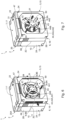
- FIGS. 1 to 6 show a first embodiment of a portable air purification system 1, the housing 2 of which is designed as a system box.
- the housing has side walls 12 which extend in the vertical direction between a bottom 6 and a top 7 of the housing 2.
- the bottom 6 of the housing 2 is formed by a bottom wall 16 and the top 7 by a ceiling wall 17, which together with the side walls 12 delimit a receiving space 3.
- An air filter unit 40 is accommodated in the receiving space 3.
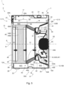
- the air filter unit has an air filter 46 and a fan 44 that can be rotated about a rotation axis R to generate an air flow from the air inlet 8 to the air outlet 9, as shown in Figures 4 and 5
- the air filter 46 and the fan 44 are arranged in a flow channel 41 which Air flow (in Figure 5 shown by the black arrows).
- Figure 5 shows the portable air purification system 1 in a longitudinal section along the rotation axis R.
- An air inlet 8 is arranged on a first side wall 12A of the housing 2.
- An air outlet 9 is arranged on second side walls 12B of the housing 2.
- the air inlet 8 comprises a coarse-mesh inlet grille 48, which is formed, for example, from the same material as the housing 2.
- the air outlet 9 comprises a coarse-mesh outlet grille 49, which is formed, for example, from the same material as the housing 2.
- the second side walls 12B extend over three sides of the housing 2, which comprise lateral side wall sections 13 and a rear side wall section 15.
- the front side wall section 14 is, according to the present example, the first side wall 12A, while the second side walls 12B comprise the lateral side wall sections 13 and the rear side wall section 15.
- the air outlet 9 also extends over three sides of the housing 2, namely over the second side walls 12B, as Figures 1 and 2
- the air outlet 9 comprises three air outlet sections, which are formed by an axial air outlet 9A and two radial air outlets 9B.
- the radial air outlets 9B are arranged on opposite sides of the housing 2.
- the axial air outlet 9A is arranged opposite the air inlet 8, i.e. opposite the first side wall 12A.
- the air inlet 8 extends over a large part of the first side wall 12A, i.e. the front side wall section 14, in the present example over more than 50 percent of the first side surface 12A.
- the axial air outlet 9A extends over a large part of the side wall opposite the first side wall 12A, i.e. the rear side wall section 15.
- the radial air outlets 9B are arranged on the half of the side walls 12 extending between the air inlet 8 and the axial air outlet 9A, which half faces the axial air outlet 9A.
- the area through which air flows through the air outlet 9 is in this case approximately 20% larger than the area through which air flows through the air inlet 8.
- the arrangement of the air outlet 9 on three different sides of the housing 2 means that an outflow from the air outlet 9 in three directions of the room creates a diffuse flow with a low outflow velocity. This is particularly advantageous when the air purification system is operated close to the floor, as dust and dirt are not unnecessarily stirred up.
- FIGS 1 and 2 also show that the housing 2 has an access 20 in the form of a cover 20A.
- the receiving space 3 is accessible to a user from above through a housing opening 2D, as is shown for example in Figure 8 is made clear.
- the access 20 is in the closed position, the receiving space 3 is not accessible to a user.
- the lid 20A is hingedly mounted on one of the side walls 12, here for example on the rear side wall 15, by means of two lid hinges 24 and can be locked or secured in the closed position by means of a rotary latch 27 arranged for example on the front side wall 14.
- a carrying handle 21 is arranged on the ceiling wall 17.
- the carrying handle 21 is in the folded state into a Carrying handle holder 22 of the ceiling wall 17 so that the upper side of the housing 2 forms a support surface.
- an intermediate floor 18 is provided as an example, as in Figures 4 , 5 , 9 and 10 which divides the receiving space 3 into a first receiving space 3A for receiving the air filter unit 40 and a second receiving space 3B.
- the intermediate floor 18 is formed integrally with the housing 2.
- the second receiving space 3B serves as a cable receiving space.
- a housing 64 enclosing a housing receiving space 64A is arranged, wherein at least one electronic component for controlling and regulating the air purification system 1 is arranged in the housing receiving space 64A.
- the housing 64 is formed at least partially integrally with the housing 2 and/or with one of the side walls 12 and/or with the intermediate floor 18, as for example in Figures 3 , 8 and 9 shown.
- the housing 64 is arranged in the area of the intermediate floor 18 and/or the intermediate floor 18 is penetrated by the housing 64, so that the housing receiving space 64A extends both into the first receiving space 3A and into the second receiving space 3B, as for example in Figure 5
- the intermediate floor 18 delimits the housing receiving space 64A and forms an enclosure wall 65 - as in Figures 4 , 9 and 10 shown -, for example an enclosure ceiling 65A or an enclosure floor 65B.
- the housing cover 65A is advantageously detachably connected to the housing base 10, for example by means of a Figure 4 indicated screw connection to form an enclosure cover.
- the housing 64 shown has two housing walls 65 formed integrally with the side walls 12 and two opposite them.
- the housing walls 65 thus extend in the vertical direction from the intermediate floor 18 into the second receiving space 3B in order to delimit the housing receiving space 64A together with the housing ceiling 65A formed as an housing cover.
- a circumferential gap extends between the vertically extending housing walls 65 of the housing 64 and the side walls 12.
- the housing 64 has two housing walls 65 formed integrally with the side walls 12 and two opposite thereto, which together with the housing ceiling 64A and the housing floor 64B delimit the housing receiving space 64A, wherein the first receiving space 3A is accessible via the housing opening 2D.
- an operating unit 66 is provided for operating the air purification system 1 by a user.
- the operating unit 66 comprises operating elements for operating the air purification system 1 by a user and/or display elements for displaying the operating state of the air purification system 1.
- the operating unit 66 is exemplary arranged on one of the side walls 12 and delimits the housing receiving space 64A at least partially to the outside.
- the housing receiving space 64A is sealed from its surroundings and/or the receiving space 3 surrounding the housing 64.
- the operating unit 66 preferably seals the housing receiving space 64A from the outside. This is particularly important for applications in the craft sector, for example on construction sites.
- the air purification system 1 has an electrical interface 67 for supplying the air purification system 1 with electrical energy.
- the air purification system 1 can thus be connected to an alternating voltage source via the electrical interface 67.
- the electrical interface 67 of the Figures 1 to 3 disclosed first embodiment is a power cable connector 671 for connecting a power cable 61 for supplying the air cleaning system 1 with an electrical voltage.
- the power cable 61 can be detachably connected or coupled to the power cable connector 671.
- FIG. 9 The illustration shown shows an alternative variant of supplying the air purification system 1 with an electrical voltage via the power cable 61.
- an alternative variant of the electrical interface 67 is used in which the power cable 61 is advantageously firmly connected to the air purification system 1, i.e. cannot be removed without tools.
- the power cable 61 is guided via the receiving space 3, in particular the second receiving space 3B, into the housing receiving space 64A.
- the power cable 61 is guided from the outside into the second receiving space 3B through an opening 63 in one of the side walls 12.
- the housing 64 has a housing recess 65C which is arranged in alignment with the opening 63 in order to guide the power cable 61 through the housing recess 65C and the opening 63 out of the receiving space 3 to the outside.
- the housing 64 is designed to have at least two feedthroughs which are designed to guide electrical conductors from the housing receiving space 64A into the receiving space 3, wherein it is preferably provided that a first feedthrough guides one or more electrical conductors from the housing receiving space 64A into the first receiving space 3A and a second feedthrough guides one or more electrical conductors, in particular the power cable 61, from the housing receiving space 64A into the second receiving space 3B.
- the power cable 61 is completely accommodated in the receiving space 3, in particular in the second receiving space 3B, without being electrically separated from the air purification unit 1. This has the advantage that the power cable 61 is firmly connected to the air purification system 1 during transport without protruding beyond the dimensions of the housing 2 in a disruptive manner during transport.
- Figure 11 discloses an alternative design of the access 20 in the form of a drawer 20B, which accommodates the power cable 61 during transport of the air purification system 1.
- the illustration shows the drawer 20B in the extended state.
- the opening 63 is formed in a drawer wall, so that the power cable 61 can be led out of the receiving space 3 even when the drawer 20B is pushed in.
- the drawer wall thus closes when the drawer 20B is pushed in.
- a side wall opening 2E which is connected to the receiving space 3.
- the housing 2 comprises a housing lower part 10, which is formed by the side walls 12 and the bottom wall 16.
- the housing lower part 10 has a first housing lower part 10A and a second housing lower part 10B, which lie vertically one above the other along a housing separation 2C.
- the first housing lower part 10A comprises the bottom wall 16.
- the cover 20A is arranged on the second housing lower part 10B.
- the air filter 46 has, by way of example, a first filter element 46A, for example a coarse filter or pre-filter, and a second filter element 46B, for example a HEPA filter, which are arranged one behind the other in the flow channel, as shown in Figures 4 and 5 shown as an example.
- a first filter element 46A for example a coarse filter or pre-filter
- a second filter element 46B for example a HEPA filter
- the fan 44 has an impeller 44A and a motor 44B that drives the impeller 44A.
- the impeller 44A has an impeller inlet 45A for sucking in air and an impeller outlet 45B.
- the fan 44 is designed as a radial fan 441.
- the flow channel 41 is delimited by a flow channel structure 42 at least in one section along the flow direction transversely to the flow direction.
- the flow channel structure 42 thus forms the walls surrounding the flow channel 41 at least in one axial section along the axis of rotation R.
- the flow channel structure 42 may, for example, comprise a collector 42A, a diffuser 42B and/or a flow guide element 47.
- the collector 42A is arranged, which guides the air towards the impeller 44A.
- the flow guide element 47 is arranged in front of the impeller 44A as an example to homogenize the flow to the impeller 44A.
- the diffuser 42B In the area of the impeller outlet 45B, the diffuser 42B is arranged, which directs the flow exiting the impeller 44A in the direction of the air outlet 9.
- Figure 5 illustrates that the impeller outlet 45B is completely covered by the radial air outlet 9B along the rotation axis R.
- the radial air outlets 9B have the same axial extension in the direction of the rotation axis R as the impeller outlet 45B.
- Figure 5 also shows that the impeller outlet 45B is completely covered by the radial air outlet 9B in the vertical direction (i.e. in the direction perpendicular to the bottom wall).
- a vertical extension of the radial air outlet 9B is therefore greater than or equal to a vertical extension of the radial fan 441, i.e. greater than or equal to an outer diameter of the impeller outlet 45B.
- the impeller outlet 45B of the radial fan 441 is thus arranged such that the air flowing out of the impeller outlet 45B can flow out of the radial air outlets 9B without further flow diversion.
- an axial air outlet 9A is arranged on the rear side wall section 15.
- the fan 44 is designed according to the Figure 5 In the embodiment shown, it is attached to the side wall 12 facing away from the air inlet 8, i.e. the rear side wall section 15.
- the fan 44 is attached to a motor mount 50, advantageously in front of the motor mount 50 in the direction of flow.
- a motor mount holder 51 is provided which fixes the motor mount 50 relative to the housing.
- the fan 44 is detachably attached to the motor mount 50 or the side wall 12, in particular by means of screw elements.
- At least two motor holders 51 are provided, which extend outward in the radial direction from the motor holder 50 and/or the rotation axis R, in particular along the housing separation 2C, as shown in Figure 2 can be seen.
- the motor mount 50 and/or motor mount holder 51 is/are formed integrally with the housing 2 and/or the motor mount 50 and/or the motor mount holder 51 is/are formed by a side wall 12 facing away from the air inlet 8.
- the side wall opposite the first side wall forms the motor recess 50 and the motor recess holders 51.
- the motor recess 50 and the motor recess holders 51 are formed integrally with the second side wall 12B.
- the housing separation 2C runs as in Figure 2 shown by way of example, by at least one of the motor mounting brackets 51.
- the air outlet 9, in particular the axial air outlet 9A, is arranged radially outwardly around the motor mount 50, so that the motor mount 50 has a fastening section in the, in particular opposite the first side wall 12A, side wall 12 and/or the motor mount 50 forms a central section in the air outlet 9.
- the motor mount 50 and the motor mount holder 51 are separate components from the housing 2.
- the motor mount holder 51 is formed integrally with the motor mount 50, for example from a metal sheet.
- the motor mount 51 is fixed to the flow channel structure 42, in particular the flow guide element 47.
- the fan 44 can therefore be aligned more precisely with respect to the flow channel structure 42 during assembly due to the shorter tolerance chain. This has a positive effect on the flow mechanics.
- the motor mount bracket 51 is screwed radially outward to the flow element 47.
- the air cleaning system 1 further comprises a coupling interface 30, with which a detachable, vertically tensile coupling to one or more system boxes 100 can be produced.
- the coupling interface 30 is, for example, in Figures 1 to 3
- the air purification system 1 can form a vertical stack together with the one or more system boxes 100.
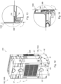
- a stack arrangement 200 consisting of the air purification system 1 and system boxes 100 is shown in Figure 12 shown.
- the coupling interface 30 comprises a lower coupling interface 30A, which provides a lower detachable, vertically tensile coupling to a lower system box 100A and an upper coupling interface 30B providing an upper releasable, vertically tensile coupling to an upper system box 100B.
- the coupling interface 30 comprises a plurality of coupling sections.
- the coupling sections expediently comprise one or more fixed coupling sections, for example one or more coupling recesses 33 and/or one or more coupling projections 34.
- the coupling interface expediently also comprises at least one (exemplarily exactly one) movably mounted coupling section, for example a coupling latch 27 or a coupling pawl.
- the coupling latch 27 is designed in particular as a rotary latch, for example as a T-shaped rotary latch.
- the upper coupling interface 30B comprises, by way of example, a plurality of upper coupling sections, which are arranged in particular on the ceiling wall 17.
- the upper coupling sections comprise coupling recesses 34, which are arranged in particular on the ceiling wall 17.
- the upper coupling sections expediently comprise a rotary latch 27, which is arranged in particular at the top of one of the side walls 12.
- the lower coupling interface 30A comprises, by way of example, a plurality of lower coupling sections, which are arranged in particular on the bottom wall 16.
- the lower coupling sections 30A comprise lower coupling projections 33, which are arranged in particular on the bottom wall 16 and are designed, for example, as feet.
- the lower coupling sections 30A expediently comprise a front coupling projection 28, which is arranged in particular on the same side wall 12 as the rotary latch 27.
- the coupling interface 30 is expediently designed such that it can be coupled to an identical coupling interface of a system box 100, which is also referred to as system box coupling interface 130.
- the upper coupling portions 30B of the coupling interface 30 are coupled to lower system box coupling portions 130A of an upper system box 100B.
- system box coupling projections 133 of the system box coupling interface 130 are engaged with coupling recesses 34 and a front system box coupling projection 128 of the upper system box 100B is engaged with the coupling latch 27.
- the lower coupling sections 30A of the coupling interface 30 can be coupled to upper system box coupling sections 130B of a lower system box 100A.
- the lower coupling projections 33 of the coupling interface 30 are in engagement with system box coupling recesses 134 of the lower system box 100A and the front coupling projection 28 is in engagement with a system box locking means 127 of the system box 100.
- the air purification system 1 can have a support structure 43 which is accommodated in the housing lower part 10.
- the support structure 43 is structurally connected to the housing lower part 10.
- the support structure 43 mechanically connects the first and the second housing parts 2A, 2B to one another.
- the first and the second housing parts 2A, 2B are fixed to one another by means of the support structure 43.
- the first housing part 2A comprises the first housing lower part 10A
- the second housing part 2B comprises the second housing lower part 10B.
- the support structure 43 forms a tensile connection between the first housing lower part 10A and the second housing lower part 10B.
- the support structure 43 has screw domes 42C, with which the support structure 43 is screwed or can be screwed to the first and second housing base parts 10A, 10B by means of screws.
- the screw domes 42C advantageously comprise upper and lower screw domes.
- the upper screw domes serve to connect the support structure to the upper housing base part 10B.
- the screws are screwed here via the second receiving space 3B through the intermediate floor 18 into the respective upper screw domes.
- the lower screw domes serve to connect the support structure 43 to the first housing base part 10A. For this purpose, screws are screwed from below through the base wall 16 into the respective lower screw domes.
- the flow channel structure 42 forms or comprises the support structure 43.
- the flow channel structure 42 can be introduced into the first housing lower part 10A during assembly and structurally connected to it by the support structure 43, for example - as explained above - screwed to it by means of the screw domes 42C.
- the second housing lower part 10B can then be placed on the first housing lower part 10A and connected to the first housing lower part 10A by the support structure 43.
- the embodiment according to the Figures 1 to 4 has a filter access 25 on one of the side walls 12.
- the filter access 25 is a part of the side wall 12 which at least partially closes a filter access opening 251 so that an air filter 46 is arranged in the flow channel 41 in a replaceable manner.
- the air filter 46 can be removed and/or inserted from the housing 2 through the filter access opening 251 so that it can be replaced or cleaned.
- the air filter 46 is, for example, pulled out of the flow channel 41 in the direction of the rotation axis R through the filter access opening 251.
- the air filter 46 is pulled out of the housing 2 transversely to the rotation axis R.
- the filter access 25 comprises, for example, an access flap 25A, as in Figure 16 , or an access cover 25B, as in Figure 15 , shown schematically.
- the access flap 25A has a hinge forming a hinge axis S, wherein the access flap 25A is, for example, rotatably mounted on a side of one of the side walls 12 facing the base wall 17 in order to release the filter access opening 251.
- the hinge axis S is therefore aligned horizontally in this case.
- the access flap 25A can be designed as a door.
- the hinge axis S is aligned vertically and arranged on one of the side walls 12.
- the access flap has an access lock 25C on its side opposite the hinge axis S, with which the access flap 25A can be locked to the housing 2 in a closed position.
- the access cover 25B is exemplarily detachably attached to the housing 2 via two opposite sides of the access cover 25B, so that it can be easily removed from the housing 2 in order to change the air filter 46.
- the filter access 25 encompasses the air inlet 8 at least partially, in the present embodiment completely.
- the air purification system 1 comprises at least one energy storage device 62C, wherein the at least one energy storage device 62C is accommodated in the housing 2 and/or integrated into the housing 2.
- the energy storage device 62C is, for example, a rechargeable battery, preferably with a nominal voltage of 18 volts or greater, for example 36 volts.
- the electrical interface 67 can comprise a battery interface 68.
- the battery interface 68 is designed to provide mechanical and electrical coupling elements for coupling to a battery pack 69 in order to supply the air purification system 1 with electrical energy.
- the battery interface 68 is arranged, for example, on the outside of the housing 2, as shown in Figures 16A and 16B. Alternatively, it can also be provided that the battery interface 68 is arranged in the second receiving space 3B.
- the battery interface 68 comprises at least a first and a second battery interface 68A, 68B and the Battery pack 69 comprises at least a first and a second battery pack 69A, 69B.
- the at least one battery pack 69, 69A, 69B is a battery pack compatible with a power tool.
- the battery interface 68 is thus designed to accommodate battery packs of a power tool.
- FIG 7 shows a second embodiment of the portable air purification system 1.
- the air purification system 1 essentially corresponds in its design to the design of the air purification system as it is shown in the Figures 1 to 5 In order to avoid repetition, reference can be made to the above explanations. Therefore, only the differences will be discussed below.
- the housing 2 of the air cleaning system 1 has a housing lower part 10, which comprises a first housing part 2A and a second housing part 2B, which lie against one another along a housing separation 2C.
- the first and second housing parts 2A, 2B each partially enclose the bottom wall 16.
- the first housing part 2A thus forms a housing front part and the second housing part 2B forms a housing rear part.
- the housing separation 2C thus runs in a direction perpendicular to the axis of rotation R.
- an axial fan 442 is used instead of the radial fan 441.
- the air cleaning system 1 therefore only has one axial air outlet 9A.
- radial air outlets 9B it is also conceivable to use radial air outlets 9B when using an axial fan.
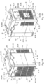
- the Figures 18 and 19 disclose a third embodiment of the portable air purification system 1.
- the air purification system 1 essentially corresponds in its design to the design of the air purification system as it is in the Figures 1 to 4 In this respect, to avoid Repetitions are referred to above. Therefore, only the differences are discussed below.
- the first side wall 12A is arranged on one of the lateral side wall sections 13, the second side walls 12B comprise the lateral side wall section 13 opposite the first side wall 12A, the front side wall section 14 and the rear side wall section 15.
- the rotation axis R of the fan 44 extends along the front side wall section 14 and/or the rear side wall section 15.
- a main flow direction of the flow channel 41 arranged in the housing 2 thus extends along the longer of the two horizontal dimensions of the housing 2. In this way, it is possible to accommodate a greater filter depth in the receiving space 3, which significantly increases the flow area.
Landscapes
- Engineering & Computer Science (AREA)
- Chemical & Material Sciences (AREA)
- Combustion & Propulsion (AREA)
- Mechanical Engineering (AREA)
- General Engineering & Computer Science (AREA)
- Chemical Kinetics & Catalysis (AREA)
- Filtering Of Dispersed Particles In Gases (AREA)
Abstract
Die Erfindung betrifft ein tragbares Luftreinigungssystem (1) umfassend ein Gehäuse (2) mit einer Bodenwand (16), einer Deckenwand (17) und sich zwischen der Bodenwand (16) und der Deckenwand (17) erstreckenden Seitenwänden (12), die einen Aufnahmeraum (3), insbesondere einen ersten Aufnahmeraum (3A), umgeben, wobei in dem Aufnahmeraum (3), insbesondere dem ersten Aufnahmeraum (3A), ein Strömungskanal (41) zur Aufnahme einer Luftfiltereinheit (40) angeordnet ist, der sich zwischen einem Lufteinlass (8) in einer ersten Seitenwand (12A) des Gehäuses (2) und einem Luftauslass (9) in zumindest einer zweiten Seitenwand (12B) des Gehäuses (2) erstreckt,
wobei die Luftfiltereinheit (40) einen Luftfilter (46) und einen um eine Rotationsachse (R) rotierbaren Lüfter (44) zur Erzeugung eines Luftstroms vom Lufteinlass (8) zum Luftauslass (9) aufweist. Eine durchströmte Fläche des Lufteinlass (8) ist kleiner oder gleich als eine durchströmte Fläche des Luftauslass (9) und/oder der Luftauslass (9) weist zumindest zwei Luftauslassabschnitte auf, die an zumindest zwei verschiedenen Seitenwänden (12), insbesondere von der ersten Seitenwand (12A) verschiedenen Seitenwänden (12), angeordnet sind.
wobei die Luftfiltereinheit (40) einen Luftfilter (46) und einen um eine Rotationsachse (R) rotierbaren Lüfter (44) zur Erzeugung eines Luftstroms vom Lufteinlass (8) zum Luftauslass (9) aufweist. Eine durchströmte Fläche des Lufteinlass (8) ist kleiner oder gleich als eine durchströmte Fläche des Luftauslass (9) und/oder der Luftauslass (9) weist zumindest zwei Luftauslassabschnitte auf, die an zumindest zwei verschiedenen Seitenwänden (12), insbesondere von der ersten Seitenwand (12A) verschiedenen Seitenwänden (12), angeordnet sind.
Description
- Die Erfindung betrifft ein tragbares Luftreinigungssystem umfassend ein Gehäuse mit einer Bodenwand, einer Deckenwand und sich zwischen der Bodenwand und der Deckenwand erstreckenden Seitenwänden, die einen Aufnahmeraum, insbesondere einen ersten Aufnahmeraum, umgeben, wobei in dem Aufnahmeraum, insbesondere dem ersten Aufnahmeraum, ein Strömungskanal zur Aufnahme einer Luftfiltereinheit angeordnet ist, der sich zwischen einem Lufteinlass in einer ersten Seitenwand des Gehäuses und einem Luftauslass in zumindest einer zweiten Seitenwand des Gehäuses erstreckt, wobei die Luftfiltereinheit einen Luftfilter und einen um eine Rotationsachse rotierbaren Lüfter zur Erzeugung eines Luftstroms vom Lufteinlass zum Luftauslass aufweist. Die Seitenwände umfassen die erste Seitenwand sowie die zumindest eine zweite Seitenwand.
- Tragbare Luftreinigungssysteme für den Einsatz auf Baustellen und im handwerklichen Bereich sind aus dem Stand der Technik allgemein bekannt. Diese werden in der Regel dazu verwendet verschmutzte oder staubige Luft aus einem abgedichteten Arbeitsraum abzusaugen und über eine Rohrleitung gefiltert an die Umwelt abzugeben. Auf diese Weise entsteht ein Unterdruck innerhalb des Arbeitsraums, der verhindert, dass verschmutzte oder staubige Luft in an den Arbeitsraum angrenzende Räume oder Bereiche gelangen. Beispielsweise beschreibt die
DE202011050155U1 eine mit Transportrollen ausgestattete Filtervorrichtung zur Raumluftfilterung für Sanierungsarbeiten in Gebäuden. Eine transportable bzw. mobile Filtervorrichtung zur Filterung eines Farbnebels ist beispielsweise aus derDE202014010481U1 bekannt. - Eine Aufgabe der Erfindung besteht darin, ein tragbares Luftreinigungssystem zur Anwendung im handwerklichen Bereich bereitzustellen. Insbesondere soll das tragbare Luftreinigungssystem zum Umluftbetrieb in geschlossenen Räumen geeignet sein. Vorzugsweise soll zudem ein einfacher Transport und schneller Auf- und Abbau ermöglicht werden.
- Die Aufgabe wird gelöst durch ein tragbares Luftreinigungssystem nach Anspruch 1. Das tragbare Luftreinigungssystem verfügt über eine durchströmte Fläche des Lufteinlass, die kleiner ist als eine durchströmte Fläche des Luftauslass. Dadurch kann die Geschwindigkeit der aus dem Luftauslass austretenden Luft reduziert werden, so dass kein störender Luftzug entsteht. Insbesondere kann auf diese Weise eine maximale Strömungsgeschwindigkeit am Luftauslass, auch als Ausströmgeschwindigkeit bezeichnet, von beispielsweise einem Meter pro Sekunde erzielt werden, ohne dabei den Luftdurchsatz aufgrund der relativ geringen Ausströmgeschwindigkeit begrenzen zu müssen. Dies ist vor allem bei Anwendungen, die auf eine Filterung der Raumluft durch Umwälzung ausgelegt sind, ein großer Vorteil. In dem Raum anwesende Personen werden auf diese Weise nicht durch hohe Ausströmgeschwindigkeiten beeinträchtigt. Zudem wird eine unnötige Aufwirbelung von Staub und Schmutz vermieden. Die Flächen de Lufteinlass und des Luftauslass meinen insbesondere die von der Luft durchströmten Flächen. Die durchströmte Fläche kann aus mehreren Teilflächen, die durch eine Gitterstruktur voneinander abgetrennt sind, gebildet sein. Diese können so ausgebildet sein, dass die eine besonders gleichförmige und/oder diffuse Strömung aus dem Luftauslass erzielt wird.
- Vorteilhafterweise ist die durchströmte Fläche des Luftauslass mindestens 20%, bevorzugt mindestens 50%, besonders bevorzugt mindestens 100% größer als die durchströmte Fläche des Lufteinlass.
- Die Seitenwände des Gehäuses begrenzen den Aufnahmeraum, insbesondere den ersten Aufnahmeraum, jeweils zumindest bereichsweise zu einer Seite des Gehäuses. Innerhalb des Gehäuses wird der Aufnahmeraum, insbesondere der erste Aufnahmeraum, durch den Strömungskanal einfassende Wände begrenzt. Der Strömungskanal ist also in dem Aufnahmeraum aufgenommen, aber nicht Teil des Aufnahmeraums.
- Die Seitenwände umfassen seitliche Seitenwandabschnitte, einen hinteren Seitenwandabschnitt und einen vorderen Seitenwandabschnitt. Die seitlichen Seitenwandabschnitte erstrecken sich zwischen dem hinteren Seitenwandabschnitt und dem vorderen Seitenwandabschnitt. Als seitliche Seitenwandabschnitte werden die (seitlichen) Schmalseiten des Gehäuses verstanden, wohingegen der hintere und der vordere Seitenwandabschnitt diejenigen Seiten sind, die jeweils größer sind als die seitlichen Seitenwandabschnitte. Eine horizontale Erstreckung des Gehäuses entlang eines seitlichen Seitenwandabschnitts ist also geringer als eine horizontale Erstreckung entlang des hinteren oder des vorderen Seitenwandabschnitts. Eine Vorderseite wird also zumindest teilweise von dem vorderen Seitenwandabschnitt, eine Rückseite zumindest teilweise von dem hinteren Seitenwandabschnitt gebildet.
- Die erste Seitenwand ist vorteilhafterweise eine von der zweiten Seitenwand verschiedene Seitenwand des Gehäuses.
- Der Strömungskanal ist zumindest in einem axialen Abschnitt entlang der Rotationsachse R radial außen von einer Strömungskanalstruktur 42 begrenzt. Die Strömungskanalstruktur kann beispielsweise einen Sammler, einen Diffusor und/oder ein Strömungsleitelement umfassen.
- Das Gehäuse kann vorteilhafterweise als stapelbare Transportkiste, insbesondere als Systemkiste, ausgeführt sein. Die horizontalen Abmessungen einer Systemkiste sind fest vorgegeben, damit die Systemkiste kompatibel zu anderen Systemkisten des gleichen Systems ist.
- Um das tragbare Luftreinigungssystem derart auszugestalten, dass es an eine andere Systemkiste ankoppelbar ist, muss das tragbare Luftreinigungssystem gemäß den horizontalen Abmessungen - also dem Grundriss - der anderen Systemkiste dimensioniert sein. Eine Systemkiste ist also dadurch gekennzeichnet, dass sie in zumindest zwei Dimensionen, beispielsweise Länge und Breite, die gleichen Abmessungen hat wie eine andere Transportkiste aus dem gleichen System und mit dieser stapelbar und vertikal zugfest koppelbar ist.
- Erfindungsgemäß kann es vorgesehen sein, dass der Lufteinlass und der Luftauslass des tragbaren Luftreinigungssystem auf gegenüberliegenden Seitenwänden des Gehäuses angeordnet sind. Zusätzlich oder alternativ kann es vorgesehen sein, dass die erste Seitenwand einer der zweiten Seitenwände in Richtung der Rotationsachse gegenüberliegend angeordnet ist. Zusätzlich oder alternativ kann es vorgesehen sein, dass der Luftauslass oder ein Abschnitt des Luftauslasses auf einer der ersten Seitenwand, vorzugsweise in Richtung der Rotationsachse, gegenüberliegenden Seitenwand angeordnet ist. Auf diese Weise ist es möglich das tragbare Luftreinigungssystem auch zu betreiben, wenn dieses einen Teil eines Stapels, beispielsweise von Systemkisten, bildet.
- Eine erfindungsgemäße Variante sieht vor, dass der Luftauslass zumindest zwei Luftauslassabschnitte aufweist, die an zumindest zwei verschiedenen Seitenwänden, insbesondere von der ersten Seitenwand verschiedenen Seitenwänden, angeordnet sind, wobei die zumindest zwei Luftauslassabschnitte an benachbarten Seitenwänden und/oder gegenüberliegenden Seitenwänden angeordnet sind. Auf diese Weise kann die durchströmte Fläche des Luftauslass maximiert werden, ohne die Abmessungen des Gehäuses ändern zu müssen. Dies ist insbesondere im Hinblick auf eine einfache Transportierbarkeit und die Unterbringung in einen Stapel von Systemkisten von Vorteil.
- Eine besonders bevorzugte erfindungsgemäße Variante sieht vor, dass die zumindest zwei Luftauslassabschnitte an drei Seitenwänden angeordnet sind, die insbesondere von der ersten Seitenwand verschieden sind. Somit kann die Fläche des Luftauslass maximiert werden, da der Luftauslass sich zumindest bereichsweise über drei der vier Seitenwände des Gehäuses erstreckt. Zudem entsteht so auch ein nicht gerichteter und somit diffuser Luftstrom der aus dem Luftauslass austretenden Luft, was zu einer angenehme Arbeitsumgebung beträgt.
- Der Lüfter umfasst beispielsweise einen Impeller, der von einem Motor angetrieben wird, wobei der Impeller einen Impellereinlass zur Ansaugung von Luft und einen Impellerauslass zum Abgeben der angesaugten Luft aufweist.
- Als Lüfter kann beispielsweise ein Radiallüfter verwendet werden, dessen Impellerauslass quer zur Rotationsachse orientiert ist. In diesem Fall ist es besonders vorteilhaft, dass der Luftauslass oder einer der Luftauslassabschnitte durch zumindest einen radialen Luftauslass gebildet ist, der an zumindest einer sich in Richtung der Rotationsachse erstreckenden Seitenwand angeordnet ist. Besonders vorteilhaft ist es, wenn der radiale Luftauslass zwei Luftauslassabschnitte aufweist, die auf gegenüberliegenden Seiten, beispielsweise an zur ersten Seitenwand benachbart angeordneten Seitenwänden angeordnet ist.
- Vorteilhafterweise ist der radiale Luftauslass in einem der ersten Seitenwand abgewandten Seitenwandabschnitt der zur ersten Seitenwand benachbart angeordneten Seitenwand oder Seitenwänden angeordnet, so dass eine direkte Ausströmung aus dem Radiallüfter in Richtung der radialen Luftauslässe erfolgen kann.
- Vorteilhafterweise ist der Impellerauslass in Richtung Entlang der Rotationsachse vollständig vom radialen Luftauslass überdeckt und/oder der Impellerauslass ist in vertikaler Richtung vollständig vom radialen Luftauslass überdeckt. Somit kann die aus den Impellerauslass ausströmende Luft zumindest teilweise ohne weitere Strömungsumlenkung aus den radialen Luftauslässen ausströmen.
- Vorteilhafterweise ist der Lüfter in dem Strömungskanal stromab des Luftfilters, insbesondere des ersten und des zweiten Luftfilters, angeordnet.
- Zusätzlich kann ebenso ein axialer Luftauslass vorgesehen sein, der sich quer zur Rotationsachse des Lüfters erstreckt und dazu dient die durchströmte Fläche des Luftauslass zu vergrößern. Vorteilhafterweise ist der axialer Luftauslass gegenüber der ersten Seitenwand und/oder dem Lufteinlass angeordnet. Der Radiallüfter die Luft also aufgrund der geringen Strömungsumlenkung mit besonders geringen Druckverlusten ansaugen und wieder ausblasen.
- Besonders bevorzugt ist vorgesehen, dass eine Hauptströmungsrichtung des in dem Gehäuse angeordneten Strömungskanals entlang der längeren der beiden horizontalen Abmessungen des Gehäuses verläuft.
- Besonders bevorzugt ist die erste Seitenwand an einer der seitlichen Seitenwandabschnitte angeordnet, die zweiten Seitenwände umfassen den der ersten Seitenwand gegenüberliegenden seitlichen Seitenwandabschnitt, den vorderen Seitenwandabschnitt und den hinteren Seitenwandabschnitt und/oder die Rotationsachse des Lüfters erstreckt sich entlang des vorderen Seitenwandabschnitts und/oder des hinteren Seitenwandabschnitts.
- Weiterhin kann in dem Gehäuse ein zweiter, von dem ersten Aufnahmeraum und dem Strömungskanal verschiedener, Aufnahmeraum vorgesehen sein. In einer Variante sind der erste und der zweite Aufnahmeraum voneinander räumlich getrennt, beispielsweise über eine Trennwand, insbesondere einen Zwischenboden. Vorteilhafterweise ist der erste Aufnahmeraum gegenüber dem zweiten Aufnahmeraum abgedichtet, insbesondere luftdicht abgedichtet. Beispielsweise kann in dem Gehäuse der Zwischenboden vorgesehen sein, der den Aufnahmeraum in den ersten Aufnahmeraum zur Aufnahme der Luftfiltereinheit und einen zweiten Aufnahmeraum unterteilt. Insbesondere ist die Luftfiltereinheit vollständig in dem ersten Aufnahmeraum aufgenommen.
- Der Zwischenboden kann parallel zur Bodenwand und/oder zur Deckenwand ausgerichtet sein. In einer vorteilhaften Ausgestaltung des Gehäuses ist der Zwischenboden integral mit dem Gehäuse ausgebildet.
- Vorteilhafterweise weist das Gehäuse einen Zugang auf, über den zumindest ein Teil des Aufnahmeraums, beispielsweise der erste oder der zweite Aufnahmeraum zugänglich ist, wobei der Zugang vorzugsweise einen Deckel und/oder eine Schublade umfasst.
- Der Deckel verschließt eine von den, insbesondere von allen, Seitenwänden berandete Gehäuseöffnung und/oder verschließt den Aufnahmeraum, insbesondere den zweiten Aufnahmeraum nach oben. Der Deckel kann beispielsweise einen von der Deckenwand senkrecht abstehenden Kragen aufweisen, so dass ein Teilvolumen des Aufnahmeraums, insbesondere des zweiten Aufnahmeraums, von dem Deckel umgeben ist.
- In einer Variante umfasst der Deckel die Deckenwand zumindest bereichsweise, vorteilhafterweise vollständig. Der Aufnahmeraum, insbesondere der zweite Aufnahmeraum, kann beispielsweise mittels des Deckels von oben oder nach oben hin verschlossen werden, so dass der Deckel in seiner Geschlossenstellung den zweiten Aufnahmeraum nach oben begrenzt. Der Deckel öffnet somit nach oben und/oder ist mittels zumindest eines Deckelscharniers drehbar und/oder klappbar an zumindest einer der Seitenwände gelagert.
- Die Schublade, wenn vorhanden, ist aus einer Schubladenöffnung der Seitenwände ausziehbar. Vorteilhafterweise bildet eine Schubladenwand einen Teil der Seitenwand, so dass die Schublade die Schubladenöffnung im eingeschobenen Zustand der Schublade verschließt.
- In der Variante, in der in dem Gehäuse der Zwischenboden angeordnet ist, ist der zweite Aufnahmeraum durch den geöffneten Zugang, insbesondere den Deckel und/oder die Schublade zugänglich und/oder nur bei geöffnetem Zugang zugänglich. In anderen Worten ist der erste Aufnahmeraum nicht über den Zugang zugänglich.
- Die Schublade bildet also einen Teil einer der Seitenwände, um den zweiten Aufnahmeraum zu verschließen, wobei die Schublade vorzugsweise aus dem zweiten Aufnahmeraum ausziehbar und/oder in den zweiten Aufnahmeraum einschiebbar ist.
- In einer Variante bildet die Schublade einen Wandbereich der Seitenwand.
- Bei der nachfolgend erläuterten Ausführungsform des tragbaren Luftreinigungssystems handelt es sich um eine bevorzugte Ausführungsform der vorgenannten tragbaren Luftreinigungssystems, aber auch im Zusammenhang mit den eingangs genannten Merkmalen oder den Merkmalen des Oberbegriffs des Anspruchs 1 um eine an sich eigenständige Erfindung.
- Das Gehäuse des tragbaren Luftreinigungssystems kann ein erstes Gehäuseteil und ein zweites Gehäuseteil aufweisen, die zusammen den Aufnahmeraum, insbesondere den ersten Aufnahmeraum, in sich aufnehmen und/oder diesen umgeben. Das erste Gehäuseteil und das zweite Gehäuseteil sind somit entlang einer Gehäuse-Trennung aneinander angeordnet, um zwei den (ersten) Aufnahmeraum umgebende Gehäuseschalen zu bilden. Auf diese Weise kann die Luftfiltereinheit bei der Montage leicht in eines der Gehäuseteile eingebaut und die beiden Gehäuseteile anschließend miteinander verbunden werden. Dies ist insbesondere dann von Vorteil, wenn das Gehäuse den zweiten Aufnahmeraum umfasst.
- In einer erfindungsgemäßen Variante trennt die die Gehäuse-Trennung das Gehäuse in ein erstes Gehäuseunterteil und ein zweites Gehäuseunterteil. Somit kann das erste Gehäuseteil das erste Gehäuseunterteil und das zweite Gehäuseteil das zweite Gehäuseunterteil sein. In diesem Fall umfasst das erste Gehäuseunterteil die Bodenwand und das zweite Gehäuseunterteil ist an der der Bodenwand abgewandten Seite des ersten Gehäuseunterteils angeordnet. In der Variante, in der das Gehäuse den Zwischenboden aufweist, umfasst das zweite Gehäuseunterteil also den Zwischenboden. Beispielsweise ist die Schublade dann in dem zweiten Gehäuseunterteil angeordnet und/oder der Deckel mittels zumindest eines Deckelscharniers drehbar und/oder klappbar an dem zweiten Gehäuseunterteil gelagert.
- In einer alternativen erfindungsgemäßen Variante kann es vorgesehen sein, dass die Gehäuse-Trennung sich in vertikaler Richtung durch das Gehäuse erstreckt, so dass die ersten und zweiten Gehäuseteile jeweils den Zwischenboden und die Bodenwand teilweise umfassen. Somit bilden das erste und das zweite Gehäuseteil ein linkes und ein rechtes Gehäuseteil. Das linke und das rechte Gehäuseteil umgeben den zweiten Aufnahmeraum zumindest teilweise. Der zweite Aufnahmeraum kann beispielsweise mittels des Deckels von oben oder nach oben hin verschlossen werden, so dass der Deckel in seiner Geschlossenstellung den zweiten Aufnahmeraum zusammen mit dem linken und dem rechten Gehäuseteil begrenzt.
- Erfindungsgemäß kann es vorgesehen sein, dass in dem Gehäuse eine Tragstruktur vorgesehen ist, die mit dem Gehäuse strukturell verbunden und geeignet ist die Luftfiltereinheit zu tragen. Insbesondere ist die Tragstruktur eine mit dem Gehäuse verbundene, aber nicht mit dem Gehäuse integrale Struktur.
- Vorteilhafterweise verbindet die Tragstruktur das erste und das zweite Gehäuseteil mechanisch miteinander oder das erste und das zweite Gehäuseteil werden mittels der Tragstruktur aneinander festgelegt. Insbesondere ist die Tragstruktur mit dem ersten Gehäuseteil und/oder dem zweiten Gehäuseteil lösbar verbunden, beispielsweise verschraubt.
- Vorteilhafterweise nimmt die Tragstruktur die Strömungskanalstruktur auf oder die Strömungskanalstruktur bildet die Tragstruktur.
- In einer Variante umfasst das Luftreinigungssystem ein Netzkabel, das wahlweise durch einen in dem Gehäuse, insbesondere in der Seitenwand, angeordneten Durchbruch aus einem Kabelaufnahmeraum herausführbar ist und/oder im Betrieb durch den Durchbruch geführt ist und beim Transport in dem Kabelaufnahmeraum aufgenommen ist oder in dem Kabelaufnahmeraum aufnehmbar ist. Der Durchbruch ist vorteilhafterweise im Bereich eines durch den Zugang gebildeten Trennbereichs angeordnet.
- Der Kabelaufnahmeraum kann innerhalb des zweiten Aufnahmeraums angeordnet sein oder von diesem umfasst werden. Der Kabelaufnahmeraum kann beispielsweise von der Schublade gebildet werden.
- Beispielsweise ist der Durchbruch im Bereich der von dem Deckel verschließbaren Gehäuseöffnung, also im Trennbereich zwischen dem Deckel und den Seitenwänden angeordnet. Der Durchbruch ist also durch eine der Seitenwände und/oder den Deckel begrenzt.
- Beispielsweise kann der Durchbruch in der Schubladenwand angeordnet sein.
- Das Luftreinigungssystem kann weiterhin eine Kopplungsschnittstelle aufweisen, mit der eine lösbare, vertikal zugfeste Kopplung zu einer oder zu mehreren Systemkisten herstellbar ist, so dass das Luftreinigungssystem zusammen mit der einen oder den mehreren Systemkisten einen vertikalen Stapel bilden kann. Die Kopplungsschnittstelle ist insbesondere eine mechanische Kopplungsschnittstelle.
- Die Kopplungsschnittstelle umfasst exemplarisch eine untere Kopplungsschnittstelle, die eine untere lösbare, vertikal zugfeste Kopplung zu einer unteren Systemkiste bereitstellt, und/oder eine obere Kopplungsschnittstelle umfasst, die eine obere lösbare, vertikal zugfeste Kopplung zu einer oberen Systemkiste bereitstellt.
- Die Kopplungsschnittstelle umfasst zweckmäßigerweise mehrere Kopplungsabschnitte. Die Kopplungsabschnitte umfassen zweckmäßigerweise einen oder mehrere feststehende Kopplungsabschnitte, beispielsweise eine oder mehrere Kopplungsvertiefungen und/oder eine oder mehrere Kopplungsvorsprünge. Zweckmäßigerweise umfasst die Kopplungsschnittstelle ferner wenigstens einen (exemplarisch genau einen) beweglich gelagerten Kopplungsabschnitt, beispielsweise einen Kopplungsriegel oder eine Kopplungsklinke. Der Kopplungsriegel ist insbesondere als Drehriegel, exemplarisch als T-förmiger Drehriegel, ausgeführt.
- Die obere Kopplungsschnittstelle umfasst exemplarisch mehrere obere Kopplungsabschnitte, die insbesondere an der Deckenwand angeordnet sind. Exemplarisch umfassen die oberen Kopplungsabschnitte Kopplungsvertiefungen, die insbesondere an der Deckenwand angeordnet sind. Zweckmäßigerweise umfassen die oberen Kopplungsabschnitte einen Drehriegel, der insbesondere an oben einer der Seitenwände angeordnet ist.
- Die untere Kopplungsschnittstelle umfasst exemplarisch mehrere untere Kopplungsabschnitte, die insbesondere an der Bodenwand angeordnet sind. Exemplarisch umfassen die unteren Kopplungsabschnitte untere Kopplungsvorsprünge, die insbesondere an der Bodenwand angeordnet sind und beispielsweise als Standfüße ausgeführt sind. Zweckmäßigerweise umfassen die unteren Kopplungsabschnitte einen vorderen Kopplungsvorsprung, der insbesondere an der gleichen Seitenwand wie der Drehriegel angeordnet ist.
- Die Kopplungsschnittstelle ist zweckmäßigerweise derart ausgeführt, dass sie mit einer identischen Kopplungsschnittstelle koppelbar ist; insbesondere sind die unteren Kopplungsabschnitte der Kopplungsschnittstelle mit oberen Kopplungsabschnitten einer identischen Kopplungsschnittstelle koppelbar. Beispielsweise können die unteren Kopplungsvorsprünge der Kopplungsschnittstelle in Eingriff mit Kopplungsvertiefungen einer identischen Kopplungsschnittstelle gebracht werden und/oder der vordere Kopplungsvorsprung kann in Eingriff mit einem Drehriegel der identischen Kopplungsschnittstelle gebracht werden und/oder der Drehriegel kann in Eingriff mit einem vorderen Kopplungsvorsprung der identischen Kopplungsschnittstelle gebracht werden.
- Außerdem ist die Erfindung auf eine Stapelanordnung, umfassend ein tragbares Luftreinigungssystem sowie eine untere Systemkiste und/oder eine obere Systemkiste gerichtet, wobei das Luftreinigungssystem auf die untere Systemkiste aufgesetzt ist und/oder die obere Systemkiste auf das Luftreinigungssystem aufgesetzt ist, so dass das Luftreinigungssystem, die untere Systemkiste und/oder die obere Systemkiste zusammen einen vertikalen Stapel bilden, und wobei eine Kopplungsschnittstelle eine untere Kopplungsschnittstelle umfasst, die eine untere lösbare, vertikal zugfeste Kopplung zu der unteren Systemkiste bereitstellt, und/oder eine obere Kopplungsschnittstelle umfasst, die eine obere lösbare, vertikal zugfeste Kopplung zu der oberen Systemkiste bereitstellt.
- Weitere exemplarische Details sowie beispielhafte Ausführungsformen werden nachstehend unter Bezugnahme auf die Figuren erläutert. Dabei zeigt
-
Figur 1 eine erfindungsgemäßes tragbares Luftreinigungssystem in Ansicht schräg von oben vorne, -
Figur 2 das Luftreinigungssystem ausFigur 1 schräg von oben hinten, -
Figur 3 das Luftreinigungssystem ausFigur 1 schräg von unten vorne, -
Figur 4 das Luftreinigungssystem ausFigur 1 in einer Explosionsdarstellung -
Figur 5 einen Schnitt längs durch das Luftreinigungssystem gemäßFigur 1 , -
Figur 6 das Luftreinigungssystem ausFigur 1 mit einer alternativen Motoraufnahme, -
Figur 7 ein erfindungsgemäßes tragbares Luftreinigungssystem in einer Variante mit Axiallüfter, -
Figur 8 ein erfindungsgemäßes Luftreinigungssystems mit geöffnetem Deckel, -
Figur 9 ein erfindungsgemäßes Luftreinigungssystem mit einem Kabelaufnahmeraum, -
Figur 10 ein erfindungsgemäßes Luftreinigungssystem mit einer alternativen Führung des Netzkabels aus dem Kabelaufnahmeraum heraus, -
Figur 11 ein Luftreinigungssystem mit einem Kabelaufnahmeraum gemäß einer Ausführung mit Schublade, -
Figur 12 eine Stapelanordnung, umfassend das Luftreinigungssystem ausFigur 1 sowie eine untere Systemkiste und eine obere Systemkiste, -
Figur 13 einen Schnitt durch einen Kopplungsabschnitt einer Kopplungsschnittstelle, -
Figur 14 einen Schnitt durch einen Drehriegel der Kopplungsschnittstelle im gekoppelten Zustand, -
Figur 15 ein erfindungsgemäßes Luftreinigungssystem mit geöffnetem Filterzugang, -
Figur 16 ein erfindungsgemäßes Luftreinigungssystem mit einem geöffneten alternativen Filterzugang, -
Figur 17A , B eine Akkuschnittstelle eines tragbaren Luftreinigungssystems, -
Figur 18 ein erfindungsgemäßes Luftreinigungssystem gemäß einer alternativen Ausführungsform von schräg links vorne, -
Figur 19 das Luftreinigungssystem gemäßFigur 17 von schräg recht vorne. - Die
Figuren 1 bis 6 zeigen ein erstes Ausführungsbeispiel eines tragbaren Luftreinigungssystems 1, dessen Gehäuse 2 als Systemkiste ausgeführt ist. Das Gehäuse weist Seitenwände 12 auf, die sich in vertikaler Richtung zwischen einer Unterseite 6 und einer Oberseite 7 des Gehäuses 2 erstrecken. Die Unterseite 6 des Gehäuses 2 wird von einer Bodenwand 16 und die Oberseite 7 von einer Deckenwand 17 gebildet, die zusammen mit den Seitenwänden 12 einen Aufnahmeraum 3 begrenzen. - In dem Aufnahmeraum 3 ist eine Luftfiltereinheit 40 aufgenommen. Die Luftfiltereinheit weist einen Luftfilter 46 und einen um eine Rotationsachse R rotierbaren Lüfter 44 zur Erzeugung eines Luftstroms vom Lufteinlass 8 zum Luftauslass 9 auf, wie dies in
Figuren 4 und5 dargestellt ist. Der Luftfilter 46 und der Lüfter 44 sind in einem Strömungskanal 41 angeordnet, der den Luftstrom (inFigur 5 durch die schwarzen Pfeile dargestellt) führt. -
Figur 5 zeigt das tragbare Luftreinigungssystem 1 in einem Längsschnitt entlang der Rotationsachse R. - An einer ersten Seitenwand 12A des Gehäuses 2 ist ein Lufteinlass 8 angeordnet. Ein Luftauslass 9 ist an zweiten Seitenwänden 12B des Gehäuses 2 angeordnet.
- Der Lufteinlass 8 umfasst ein grobmaschiges Einlassgitter 48, welches beispielsweise aus dem gleichen Material geformt ist wie das Gehäuse 2. Ebenso umfasst der Luftauslass 9 ein grobmaschiges Auslassgitter 49, welches beispielsweise aus dem gleichen Material geformt ist wie das Gehäuse 2.
- In dem vorliegenden Fall erstrecken sich die zweiten Seitenwände 12B über drei Seiten des Gehäuses 2, welche seitliche Seitenwandabschnitte 13 und einen hinteren Seitenwandabschnitt 15 umfassen. Der vordere Seitenwandabschnitt 14 ist gemäß dem vorliegenden Beispiel die erste Seitenwand 12A, während die zweiten Seitenwände 12B die seitlichen Seitenwandabschnitte 13 und den hinteren Seitenwandabschnitt 15 umfassen.
- Der Luftauslass 9 erstreckt sich ebenso über drei Seiten des Gehäuses 2, nämlich über die zweiten Seitenwände 12B, wie
Figuren 1 und 2 darstellen. Der Luftauslass 9 umfasst vorliegend drei Luftauslassabschnitte, die von einem axialen Luftauslass 9A und zwei radialen Luftauslässen 9B gebildet werden. Die radialen Luftauslässe 9B sind auf einander gegenüberliegenden Seiten des Gehäuses 2 angeordnet. Der axiale Luftauslass 9A ist gegenüber dem Lufteinlass 8, also gegenüber der ersten Seitenwand 12A, angeordnet. - Der Lufteinlass 8 erstreckt sich über einen Großteil der ersten Seitenwand 12A, also dem vorderen Seitenwandabschnitt 14, im vorliegenden Beispiel über mehr als 50 Prozent der ersten Seitenfläche 12A.
- Der axiale Luftauslass 9A erstreckt sich über einen Großteil der der ersten Seitenwand 12A gegenüberliegenden Seitenwand, also dem hinteren Seitenwandabschnitt 15.
- Die radialen Luftauslässe 9B sind an der dem axialen Luftauslass 9A zugewandten Hälfte der sich zwischen Lufteinlass 8 und axialem Luftauslass 9A erstreckenden Seitenwände 12 angeordnet.
- Die durchströmte Fläche des Luftauslasses 9 ist vorliegend ca. 20% größer als die Durchströmte Fläche des Lufteinlass 8. Zudem bewirkt die Anordnung des Luftauslasses 9 auf drei verschiedenen Seiten des Gehäuses 2, dass eine Abströmung aus dem Luftauslass 9 in drei Richtungen des Raumes eine diffuse Strömung mit geringer Ausströmgeschwindigkeit erzeugt. Dies ist insbesondere bei bodennahem Betrieb des Luftreinigungssystems vor Vorteil, da Staub und Verschmutzungen nicht unnötig aufgewirbelt werden.
-
Figuren 1 und 2 zeigen ebenfalls, dass das Gehäuse 2 einen Zugang 20 in Gestalt eines Deckels 20A aufweist. In einer Offenstellung des Zugangs 20 ist der Aufnahmeraum 3 für einen Nutzer von oben durch eine Gehäuseöffnung 2D zugänglich, wie dies zum Beispiel inFigur 8 verdeutlicht wird. In einer Geschlossenstellung des Zugangs 20 ist der Aufnahmeraum 3 für einen Nutzer nicht zugänglich. Der Deckel 20A ist mittels zweier Deckelscharniere 24 an einer der Seitenwände 12, hier exemplarisch an der hinteren Seitenwand 15, klappbar gelagert und ist mittels eines, exemplarisch an der vorderen Seitenwand 14 angeordneten, Drehriegels 27 in der Geschlossenstellung arretierbar oder abschließbar. - An der Deckenwand 17 ist ein Tragegriff 21 angeordnet. Der Tragegriff 21 ist im Eingeklappten Zustand in eine Tragegriffaufnahme 22 der Deckenwand 17 eingelassen, sodass die Oberseite des Gehäuses 2 eine Auflagefläche bildet.
- In dem Gehäuse 2 ist exemplarisch ein Zwischenboden 18 vorgesehen, wie in
Figuren 4 ,5 ,9 und 10 dargestellt, der den Aufnahmeraum 3 in einen ersten Aufnahmeraum 3A zur Aufnahme der Luftfiltereinheit 40 und einen zweiten Aufnahmeraum 3B unterteilt. Der Zwischenboden 18 ist integral mit dem Gehäuse 2 ausgebildet. WieFiguren 9 und 10 zeigen, dient der zweite Aufnahmeraum 3B als Kabelaufnahmeraum. - Bei der nachfolgend erläuterten Ausführungsform des tragbaren Luftreinigungssystems handelt es sich um eine bevorzugte Ausführungsform der vorgenannten tragbaren Luftreinigungssystems, aber auch im Zusammenhang mit den eingangs genannten Merkmalen oder den Merkmalen des Oberbegriffs des Anspruchs 1 um eine an sich eigenständige Erfindung.
- In dem Aufnahmeraum 3 ist eine einen Einhausungs-Aufnahmeraum 64A umschließende Einhausung 64 angeordnet, wobei in dem Einhausungs-Aufnahmeraum 64A zumindest eine elektronische Komponente zur Steuerung und Regelung des Luftreinigungssystems 1 angeordnet ist. Exemplarisch ist die Einhausung 64 zumindest teilweise integral mit dem Gehäuse 2 und/oder mit einer der Seitenwände 12 und/oder mit dem Zwischenboden 18 ausgebildet, wie beispielsweise in
Figuren 3 ,8 und9 gezeigt. - Beispielsweise ist die Einhausung 64 im Bereich des Zwischenbodens 18 angeordnet und/oder der Zwischenboden 18 von der Einhausung 64 durchsetzt, so dass sich der Einhausungs-Aufnahmeraum 64A sowohl in den ersten Aufnahmeraum 3A, als auch in den zweiten Aufnahmeraum 3B erstreckt, wie beispielsweise in
Figur 5 dargestellt. Alternativ kann es ebenso vorgesehen sein, dass der Zwischenboden 18 den Einhausungs-Aufnahmeraum 64A begrenzt und eine Einhausungswand 65 bildet - wie inFiguren 4 ,9 und 10 dargestellt -, beispielsweise eine Einhausung-Decke 65A oder einen Einhausungs-Boden 65B. - Die Einhausungs-Decke 65A ist vorteilhafterweise lösbar mit dem Gehäuseunterteil 10 verbunden, beispielsweise mittels einer in
Figur 4 angedeuteten Schraubverbindung, um einen Einhausungs-Deckel zu bilden. - Die in
Figuren 4 und9 gezeigte Einhausung 64 weist zwei integral mit den Seitenwänden 12 ausgebildete und zwei diesen gegenüberliegende Einhausungswände 65 auf. Die Einhausungswände 65 erstrecken sich somit in vertikaler Richtung vom Zwischenboden 18 in den zweiten Aufnahmeraum 3B um den Einhausungs-Aufnahmeraum 64A zusammen mit der als Einhausungs-Deckel ausgebildeten Einhausungs-Decke 65A zu begrenzen. - Bei der in
Figur 10 gezeigten Einhausung 64 erstreckt sich ein umlaufender Spalt zwischen den sich vertikal erstreckenden Einhausungswänden 65 der Einhausung 64 und den Seitenwänden 12. - Bei der in
Figur 8 dargestellten Variante des Luftreinigungssystems 1 weist die Einhausung 64 zwei integral mit den Seitenwänden 12 ausgebildete und zwei diesen gegenüberliegende Einhausungswände 65 auf, die zusammen mit der Einhausungs-Decke 64A und dem Einhausungs-Boden 64B den Einhausungs-Aufnahmeraum 64A begrenzen, wobei der erste Aufnahmeraum 3A über die Gehäuseöffnung 2D zugänglich ist. - Weiterhin ist eine Bedieneinheit 66 zur Bedienung des Luftreinigungssystem 1 durch einen Nutzer vorgesehen. Die Bedieneinheit 66 umfasst Bedienelemente zur Bediendung des Luftreinigungssystems 1 durch einen Benutzer und/oder Anzeigeelemente zur Anzeige des Betriebszustands des Luftreinigungssystems 1. Die Bedieneinheit 66 ist exemplarisch an einer der Seitenwände 12 angeordnet und begrenzt den Einhausungs-Aufnahmeraum 64A zumindest bereichsweise nach außen.
- Der Einhausungs-Aufnahmeraum 64A ist gegenüber seiner Umgebung und/oder dem die Einhausung 64 umgebenden Aufnahmeraum 3 abgedichtet. Vorzugsweise dichtet die Bedieneinheit 66 den Einhausungs-Aufnahmeraum 64A nach außen ab. Dies ist besonders bei Anwendungen im handwerklichen Bereich, beispielsweise auf Baustellen bedeutsam.
- Das Luftreinigungssystem 1 weist eine elektrische Schnittstelle 67 zur Versorgung des Luftreinigungssystems 1 mit elektrischer Energie auf. Das Luftreinigungssystem 1 ist somit über die elektrische Schnittstelle 67 an eine Wechselspannungsquelle anschließbar.
- Die die elektrische Schnittstelle 67 des in den
Figuren 1 bis 3 offenbarten ersten Ausführungsbeispiels ist ein Netzkabelanschlusses 671 zum Anschluss eines Netzkabels 61 zur Versorgung des Luftreinigungssystem 1 mit einer elektrischen Spannung. Das Netzkabel 61 ist lösbar an den Netzkabelanschluss 671 anschließbar oder ankoppelbar. - In der in
Figur 9 gezeigten Darstellung ist eine alternative Variante der Versorgung des Luftreinigungssystem 1 mit einer elektrischen Spannung über das Netzkabel 61 dargestellt. In anderen Worten wird eine alternative Variante der elektrischen Schnittstelle 67 verwendet bei der das Netzkabel 61 vorteilhafterweise fest, also nicht werkzeuglos lösbar, mit dem Luftreinigungssystem 1 verbunden ist. Das Netzkabel 61 wird über den Aufnahmeraum 3, insbesondere den zweiten Aufnahmeraum 3B, in den Einhausungs-Aufnahmeraum 64A geführt. Das Netzkabel 61 ist dabei durch einen Durchbruch 63 in einer der Seitenwände 12 von außen in den zweiten Aufnahmeraum 3B geführt. - In einer in
Figur 10 dargestellten Variante der Einhausung 64, weist die Einhausung 64 eine Einhausungs-Ausnehmung 65C auf, die fluchtend mit dem Durchbruch 63 angeordnet ist, um das Netzkabel 61 durch die Einhausungs-Ausnehmung 65C und den Durchbruch 63 aus dem Aufnahmeraum 3 nach außen zu führen. - Die Einhausung 64 ist ausgebildet zumindest zwei Durchführungen aufzuweisen, die dazu ausgebildet sind elektrische Leiter aus dem Einhausungs-Aufnahmeraum 64A in den Aufnahmeraum 3 zu führen, wobei bevorzugt vorgesehen ist, dass eine erste Durchführung einen oder mehrere elektrische Leiter aus dem Einhausungs-Aufnahmeraum 64A in den ersten Aufnahmeraum 3A führt und eine zweite Durchführung einen oder mehrere elektrische Leiter, insbesondere das Netzkabel 61, aus dem Einhausungs-Aufnahmeraum 64A in den zweiten Aufnahmeraum 3B führt.
- Das Netzkabel 61 ist während des Transports des Luftreinigungssystems 1 vollständig in dem Aufnahmeraum 3, insbesondere in dem zweiten Aufnahmeraum 3B, aufgenommen, ohne elektrisch von der Luftreinigungseinheit 1 getrennt zu sein. Dies hat den Vorteil, dass das Netzkabel 61 beim Transport fest mit dem Luftreinigungssystem 1 verbunden ist, ohne beim Transport störend über die Abmessungen des Gehäuses 2 hinauszuragen.
-
Figur 11 offenbart eine alternative Gestaltung des Zugangs 20 in Gestalt einer Schublade 20B, die das Netzkabel 61 während des Transports des Luftreinigungssystem 1 aufnimmt. Die Darstellung zeigt die Schublade 20B im ausgezogenen Zustand. Der Durchbruch 63 ist vorliegend in einer Schubladenwand ausgebildet, so dass das Netzkabel 61 auch im eingeschobenen Zustand der Schublade 20B aus dem Aufnahmeraum 3 herausführbar ist. Die Schubladenwand verschließt also im eingeschobenen Zustand der Schublade 20B eine Seitenwandöffnung 2E, die mit dem Aufnahmeraum 3 verbunden ist. - Das Gehäuse 2 umfasst ein Gehäuseunterteil 10, welches von den Seitenwänden 12 und der Bodenwand 16 gebildet wird. Das Gehäuseunterteil 10 weist gemäß dem vorliegenden Ausführungsbeispiel ein erstes Gehäuseunterteil 10A und ein zweites Gehäuseunterteil 10B auf, die entlang einer Gehäuse-Trennung 2C vertikal übereinander aneinander liegen. Das erste Gehäuseunterteil 10A umfasst die Bodenwand 16. Der Deckel 20A ist an dem zweiten Gehäuseunterteil 10B angeordnet.
- Der Luftfilter 46 weist exemplarisch ein erstes Filterelement 46A, beispielsweise einen Grobfilter oder Vorfilter, und ein zweites Filterelement 46B, beispielsweise einen HEPA-Filter, auf, die in dem Strömungskanal hintereinander angeordnet sind, wie in
Figuren 4 und5 exemplarisch dargestellt. - Der Lüfter 44 weist einen Impeller 44A und einen den Impeller 44A antreibenden Motor 44B auf. Der Impeller 44A weist einen Impellereinlass 45A zur Ansaugung von Luft und einen Impellerauslass 45B auf. Der Lüfter 44 ist in dem vorliegenden Beispiel als Radiallüfter 441 ausgestaltet.
- Der Strömungskanal 41 ist zumindest in einem Abschnitt entlang der Strömungsrichtung quer zur Strömungsrichtung von einer Strömungskanalstruktur 42 begrenzt. Die Strömungskanalstruktur 42 bildet also zumindest in einem axialen Abschnitt entlang der Rotationsachse R die den Strömungskanal 41 umgebenden Wände.
- Die Strömungskanalstruktur 42 kann beispielsweise einen Sammler 42A, einen Diffusor 42B und/oder ein Strömungsleitelement 47 umfassen.
- Zwischen dem Luftfilter 46 und dem Lüfter 44 ist der Sammler 42A angeordnet, der die Luft in Richtung des Impellers 44A führt. Vor dem Impeller 44A ist exemplarisch das Strömungsleitelement 47 zur Homogenisierung der Anströmung des Impellers 44A angeordnet.
- Im Bereich des Impellerauslass 45B ist der Diffusor 42B angeordnet, der die aus dem Impeller 44A austretende Strömung in Richtung des Luftauslass 9 leitet.
-
Figur 5 verdeutlicht, dass der Impellerauslass 45B Entlang der Rotationsachse R vollständig vom radialen Luftauslass 9B überdeckt wird. Exemplarisch haben die radialen Luftauslässe 9B die gleiche axiale Erstreckung in Richtung der Rotationsachse R wie der Impellerauslass 45B. -
Figur 5 verdeutlicht ebenso, dass der Impellerauslass 45B in vertikaler Richtung (also in Richtung senkrecht zur Bodenwand) vollständig vom radialen Luftauslass 9B überdeckt wird. Eine vertikale Erstreckung des radialen Luftauslass 9B ist also größer oder gleich als eine vertikale Erstreckung des Radiallüfters 441, also größer oder gleich groß wie ein Außendurchmesser des Impellerauslass 45B. - Der Impellerauslass 45B des Radiallüfters 441 ist also so angeordnet ist, dass die aus den Impellerauslass 45B ausströmende Luft ohne weitere Strömungsumlenkung aus den radialen Luftauslässen 9B ausströmen kann.
- In dem gezeigten Ausführungsbeispiel ist zusätzlich zu den radialen Luftauslässen 9B ein axialer Luftauslass 9A an dem hinteren Seitenwandabschnitt 15 angeordnet.
- Der Lüfter 44 ist gemäß dem in
Figur 5 gezeigten Ausführungsbeispiel an der dem Lufteinlass 8 abgewandten Seitenwand 12, also dem hinteren Seitenwandabschnitt 15, befestigt. - Der Lüfter 44 ist an einer Motoraufnahme 50, vorteilhafterweise in Strömungsrichtung vor der Motoraufnahme 50, befestigt. Exemplarisch ist ein Motoraufnahmehalter 51 vorgesehen, der die Motoraufnahme 50 relativ zum Gehäuse festlegt. Der Lüfter 44 ist an der Motoraufnahme 50 oder der Seitenwand 12 lösbar, insbesondere mittels Schraubelementen, befestigt.
- Vorteilhafterweise sind zumindest zwei Motoraufnahmehalter 51 vorgesehen, die sich in radialer Richtung von der Motoraufnahme 50 und/oder der Rotationsachse R nach außen erstrecken, insbesondere entlang der Gehäuse-Trennung 2C, wie dies in
Figur 2 zu sehen ist. - Die Motoraufnahme 50 und/oder Motoraufnahmehalter 51 integral mit dem Gehäuse 2 ausgebildet ist/sind und/oder die Motoraufnahme 50 und/oder der Motoraufnahmehalter 51 von einer dem Lufteinlass 8 abgewandten Seitenwand 12 gebildet wird/werden.
- In dem Ausführungsbeispiel gemäß
Figur 4 und5 bildet die der ersten Seitenwand gegenüberliegende Seitenwand die Motoraufnahme 50 und die Motoraufnahmehalter 51. In anderen Worten sind die Motorausnahme 50 und die Motoraufnahmehalter 51 integral mit der zweiten Seitenwand 12B ausgebildet. - Gemäß einer vorteilhaften Ausgestaltung verläuft die Gehäuse-Trennung 2C, wie in
Figur 2 exemplarisch gezeigt, durch zumindest einen der Motoraufnahmehalter 51. - Der Luftauslass 9, insbesondere der axiale Luftauslass 9A, ist radial außen um die Motoraufnahme 50 herum angeordnet, so dass die Motoraufnahme 50 einen Befestigungsabschnitt in der, insbesondere der ersten Seitenwand 12A gegenüberliegenden, Seitenwand 12 ausbildet und/oder die Motoraufnahme 50 einen zentralen Abschnitt in dem Luftauslass 9 bildet.
- In einer alternativen, in
Figur 6 dargestellten, Ausgestaltungsform ist die Motoraufnahme 50 und die Motoraufnahmehalter 51 von dem Gehäuse 2 separate Bauteile. Exemplarisch sind die Motoraufnahmehalter 51 integral mit der Motoraufnahme 50, beispielsweise aus einem Metallblech, gebildet. - Gemäß der in
Figur 6 dargestellten Ausführungsform ist der Motoraufnahmehalter 51 an der Strömungskanalstruktur 42, insbesondere dem Strömungsleitelement 47 festgelegt. Somit kann der Lüfter 44 bei der Montage auf Grund der kürzeren Toleranzkette genauer gegenüber der Strömungskanalstruktur 42 ausgerichtet werden. Dies wirkt sich strömungsmechanisch positiv aus. - Vorliegend ist der Motoraufnahmehalter 51 radial außen an dem Strömungselement 47 angeschraubt.
- Das Luftreinigungssystem 1 weist weiterhin eine Kopplungsschnittstelle 30 auf, mit der eine lösbare, vertikal zugfeste Kopplung zu einer oder zu mehreren Systemkisten 100 herstellbar ist. Die Kopplungsschnittstelle 30 ist beispielsweise in
Figuren 1 bis 3 zu erkennen. Das Luftreinigungssystem 1 kann zusammen mit der einen oder den mehreren Systemkisten 100 einen vertikalen Stapel bilden kann. Eine Stapelanordnung 200 bestehend aus dem Luftreinigungssystem 1 und Systemkisten 100 ist inFigur 12 dargestellt. - Die Kopplungsschnittstelle 30 umfasst eine untere Kopplungsschnittstelle 30A, die eine untere lösbare, vertikal zugfeste Kopplung zu einer unteren Systemkiste 100A bereitstellt, und eine obere Kopplungsschnittstelle 30B, die eine obere lösbare, vertikal zugfeste Kopplung zu einer oberen Systemkiste 100B bereitstellt.
- Die Kopplungsschnittstelle 30 umfasst mehrere Kopplungsabschnitte. Die Kopplungsabschnitte umfassen zweckmäßigerweise einen oder mehrere feststehende Kopplungsabschnitte, beispielsweise eine oder mehrere Kopplungsvertiefungen 33 und/oder eine oder mehrere Kopplungsvorsprünge 34. Zweckmäßigerweise umfasst die Kopplungsschnittstelle ferner wenigstens einen (exemplarisch genau einen) beweglich gelagerten Kopplungsabschnitt, beispielsweise einen Kopplungsriegel 27 oder eine Kopplungsklinke. Der Kopplungsriegel 27 ist insbesondere als Drehriegel, exemplarisch als T-förmiger Drehriegel, ausgeführt.
- Die obere Kopplungsschnittstelle 30B umfasst exemplarisch mehrere obere Kopplungsabschnitte, die insbesondere an der Deckenwand 17 angeordnet sind. Exemplarisch umfassen die oberen Kopplungsabschnitte Kopplungsvertiefungen 34, die insbesondere an der Deckenwand 17 angeordnet sind. Zweckmäßigerweise umfassen die oberen Kopplungsabschnitte einen Drehriegel 27, der insbesondere oben an einer der Seitenwände 12 angeordnet ist.
- Die untere Kopplungsschnittstelle 30A umfasst exemplarisch mehrere untere Kopplungsabschnitte, die insbesondere an der Bodenwand 16 angeordnet sind. Exemplarisch umfassen die unteren Kopplungsabschnitte 30A untere Kopplungsvorsprünge 33, die insbesondere an der Bodenwand 16 angeordnet sind und beispielsweise als Standfüße ausgeführt sind. Zweckmäßigerweise umfassen die unteren Kopplungsabschnitte 30A einen vorderen Kopplungsvorsprung 28, der insbesondere an der gleichen Seitenwand 12 wie der Drehriegel 27 angeordnet ist.
- Die Kopplungsschnittstelle 30 ist zweckmäßigerweise derart ausgeführt, dass sie mit einer identischen Kopplungsschnittstelle einer Systemkiste 100 koppelbar ist, welche auch als Systemkisten-Kopplungsschnittstelle 130 bezeichnet ist.
- In
Figuren 13 und 14 ist die obere Kopplungsabschnitte 30B der Kopplungsschnittstelle 30 mit unteren Systemkisten-Kopplungsabschnitten 130A einer oberen Systemkiste 100B gekoppelt. Hierbei sind Systemkisten-Kopplungsvorsprünge 133 der Systemkisten-Kopplungsschnittstelle 130 in Eingriff mit Kopplungsvertiefungen 34 und ein vorderer Systemkisten-Kopplungsvorsprung 128 der oberen Systemkiste 100B ist in Eingriff mit dem Kopplungsriegel 27. - Ebenso können die unteren Kopplungsabschnitte 30A der Kopplungsschnittstelle 30 mit oberen Systemkisten-Kopplungsabschnitten 130B einer unteren Systemkiste 100A gekoppelt sein. Hierbei sind die unteren Kopplungsvorsprünge 33 der Kopplungsschnittstelle 30 in Eingriff mit Systemkisten-Kopplungsvertiefungen 134 der unteren Systemkiste 100A und der vordere Kopplungsvorsprung 28 ist in Eingriff mit einem Systemkisten-Verriegelungsmittel 127 der Systemkiste 100.
- Wie in
Figur 4 dargestellt, kann das Lufteinigungssystem 1 eine Tragstruktur 43 aufweisen, die in dem Gehäuseunterteil 10 aufgenommen ist. Die Tragstruktur 43 ist strukturell mit dem Gehäuseunterteil 10 verbunden. Insbesondere verbindet die Tragstruktur 43 das erste und das zweite Gehäuseteil 2A, 2B mechanisch miteinander. Somit werden das erste und das zweite Gehäuseteil 2A, 2B mittels der Tragstruktur 43 aneinander festgelegt. Dies ist besonders vorteilhaft, wenn das erste Gehäuseteil 2A das erste Gehäuseunterteil 10A und das zweite Gehäuseteil 2B das zweite Gehäuseunterteil 10B umfasst. In diesem Fall bildet die Tragstruktur 43 eine zugfeste Verbindung zwischen erstem Gehäuseunterteil 10A und zweitem Gehäuseunterteil 10B. - Vorliegend weist die Tragstruktur 43 Schraubdome 42C auf, mit denen die Tragstruktur 43 mittels Schrauben an dem ersten und dem zweiten Gehäuseunterteil 10A, 10B angeschraubt ist oder anschraubbar ist. Die Schraubdome 42C umfassen vorteilhafterweise obere und untere Schraubdome. Die oberen Schraubdome dienen der Verbindung der Tragstruktur mit dem oberen Gehäuseunterteil 10B. Die Schrauben werden hier über den zweiten Aufnahmeraum 3B durch den Zwischenboden 18 in die jeweiligen oberen Schraubdome eingeschraubt. Die unteren Schraubdome dienen dazu die Tragstruktur 43 mit dem ersten Gehäuseunterteil 10A zu verbinden. Hierzu werden Schrauben von unten durch die Bodenwand 16 in die jeweiligen unteren Schraubdome eingeschraubt.
- Vorliegend bildet oder umfasst die Strömungskanalstruktur 42 die Tragstruktur 43.
- Auf diese Weise kann die Strömungskanalstruktur 42 bei der Montage in das erste Gehäuseunterteil 10A eingebracht und durch die Tragstruktur 43 mit diesem strukturell verbunden, beispielsweise - wie oben erläutert - mittels den Schraubdomen 42C an diesem verschraubt werden. Anschließend kann das zweite Gehäuseunterteil 10B auf das erste Gehäuseunterteil 10A aufgesetzt und durch die Tragstruktur 43 mit dem ersten Gehäuseunterteil 10A verbunden werden.
- Dies ist besonders vorteilhaft, wenn das Luftreinigungssystem 1 an einem der Kopplungsabschnitte 30A, 30B mit einer oder mehrerer Systemkisten 100 gekoppelt ist, da die vertikalen Zugkräfte somit von der Tragstruktur 43 aufgenommen werden.
- Das Ausführungsbeispiel gemäß den
Figuren 1 bis 4 weist einen Filterzugang 25 auf einer der Seitenwände 12 auf. Der Filterzugang 25 ist ein Teil der Seitenwand 12, der eine Filterzugangsöffnung 251 zumindest teilweise verschließt, so dass ein Luftfilter 46 auswechselbar in dem Strömungskanal 41 angeordnet ist. - Durch die Filterzugangsöffnung 251 ist der Luftfilter 46 aus dem Gehäuse 2 entnehmbar und/oder einsetzbar, so dass er ausgewechselt oder gereinigt werden kann. Der Luftfilter 46 wird exemplarisch in Richtung der Rotationsachse R durch die Filterzugangsöffnung 251 aus dem Strömungskanal 41 gezogen. In einer alternativen nicht dargestellten Variante wird der Luftfilter 46 quer zur Rotationsachse R aus dem Gehäuse 2 gezogen.
- Der Filterzugang 25 umfasst beispielsweise eine Zugangsklappe 25A, wie in
Figur 16 , oder ein Zugangsdeckel 25B, wie inFigur 15 , schematisch dargestellt. - Die Zugangsklappe 25A weist ein eine Scharnierachse S bildendes Scharnier auf, wobei die Zugangsklappe 25A exemplarisch an einer der Bodenwand 17 zugewandten Seite einer der Seitenwände 12 drehbar gelagert ist, um die Filterzugangsöffnung 251 freizugeben. Die Scharnierachse S ist in diesem Fall also horizontal ausgerichtet. In ähnlicher Weise kann die Zugangsklappe 25A als Tür ausgebildet sein. In diesem Fall ist die Scharnierachse S vertikal ausgerichtet und an einer der Seitenwände 12 angeordnet. Die Zugangsklappe weist auf ihrer der Scharnierachse S gegenüberliegenden Seite eine Zugangsverriegelung 25C auf mit der die Zugangsklappe 25A in einer Geschlossenstellung mit dem Gehäuse 2 verriegelt werden kann.
- Der Zugangsdeckel 25B ist exemplarisch über zwei auf entgegengesetzten Seiten des Zugangsdeckels 25B lösbar an dem Gehäuse 2 befestigt, so dass er in einfacher Weise von dem Gehäuse 2 entfernt werden kann, um den Luftfilter 46 zu wechseln.
- Vorteilhafterweise umfasst der Filterzugang 25 den Lufteinlass 8 zumindest teilweise, in dem vorliegenden Ausführungsbeispiel vollständig.
- Gemäß einer Variante umfasst das Luftreinigungssystem 1 zumindest einen Energiespeicher 62C, wobei der zumindest eine Energiespeicher 62C in dem Gehäuse 2 aufgenommen ist und/oder in das Gehäuse 2 integriert ist. Der Energiespeicher 62C ist beispielsweise ein wiederaufladbarer Akku, vorzugsweise mit einer Nennspannung von 18 Volt oder größer, beispielsweise 36 Volt.
- In einer Variante ist in dem Gehäuse 2 eine Ladevorrichtung vorgesehen, mit der der zumindest eine Energiespeicher 62) über die elektrische Schnittstelle 67 aufladbar ist.
- Zusätzlich oder alternativ zu den zuvor beschriebenen Varianten kann die elektrische Schnittstelle 67 eine Akku-Schnittstelle 68 umfassen. Die Akku-Schnittstelle 68 ist ausgebildet um mechanische und elektrische Kopplungselemente zur Kopplung mit einem Akkupack 69 bereitzustellen, um das Luftreinigungssystem 1 mit elektrischer Energie zu versorgen. Die Akku-Schnittstelle 68 ist exemplarisch außen an dem Gehäuse 2 angeordnet, wie dies in Figuren 16A und 16B gezeigt ist. Alternativ kann es auch vorgesehen sein, dass die Akku-Schnittstelle 68 in dem zweiten Aufnahmeraum 3B angeordnet ist.
- In einer Alternative umfasst die Akku-Schnittstelle 68 zumindest eine erste und eine zweite Akkuschnittstelle 68A, 68B und das Akkupack 69 umfasst zumindest ein erstes und ein zweites Akkupack 69A, 69B.
- Vorzugsweise ist das zumindest eine Akkupack 69, 69A, 69B ein mit einem Powertool kompatibles Akkupack. Die Akku-Schnittstelle 68 somit ausgebildet Akkupacks eines Powertools aufzunehmen.
-
Figur 7 zeigt ein zweites Ausführungsbeispiel des tragbaren Luftreinigungssystems 1. Das Luftreinigungssystem 1 entspricht in seiner Gestaltung im Wesentlichen der Ausgestaltung des Luftreinigungssystems, wie es in denFiguren 1 bis 5 gezeigt ist. Insofern kann zur Vermeidung von Wiederholungen auf die vorstehenden Ausführungen verwiesen werden. Nachstehend wird daher lediglich auf die Unterschiede eingegangen. - Das Gehäuse 2 des Luftreinigungssystems 1 weist ein Gehäuseunterteil 10 auf, welches ein erstes Gehäuseteil 2A und ein zweites Gehäuseteil 2B umfasst, die entlang einer Gehäuse-Trennung 2C aneinander liegen. Das erste und das zweite Gehäuseteil 2A, 2B umfassen die Bodenwand 16 jeweils teilweise. Das erste Gehäuseteil 2A bildet also ein Gehäusevorderteil und das zweite Gehäuseteil 2B ein Gehäusehinterteil. Die Gehäuse-Trennung 2C verläuft also in einer Richtung senkrecht zur Rotationsachse R.
- In dem vorliegenden Ausführungsbeispiel ist statt des Radiallüfters 441 ein Axiallüfter 442 verwendet. Somit weist das Luftreinigungssystem 1 lediglich einen axialen Luftauslass 9A auf. Grundsätzlich ist es denkbar auch bei Verwendung eines Axiallüfters radiale Luftauslässe 9B zu verwenden.
- Die
Figuren 18 und 19 offenbaren ein drittes Ausführungsbeispiel des tragbaren Luftreinigungssystems 1. Das Luftreinigungssystem 1 entspricht in seiner Gestaltung im Wesentlichen der Ausgestaltung des Luftreinigungssystems, wie es in denFiguren 1 bis 4 gezeigt ist. Insofern kann zur Vermeidung von Wiederholungen auf die vorstehenden Ausführungen verwiesen werden. Nachstehend wird daher lediglich auf die Unterschiede eingegangen. - Die erste Seitenwand 12A ist vorliegend an einer der seitlichen Seitenwandabschnitte 13 angeordnet, die zweiten Seitenwände 12B umfassen vorliegend den der ersten Seitenwand 12A gegenüberliegenden seitlichen Seitenwandabschnitt 13, den vorderen Seitenwandabschnitt 14 und den hinteren Seitenwandabschnitt 15.
- Die Rotationsachse R des Lüfters 44 erstreckt sich entlang des vorderen Seitenwandabschnitts 14 und/oder des hinteren Seitenwandabschnitts 15. Eine Hauptströmungsrichtung des in dem Gehäuse 2 angeordneten Strömungskanals 41 erstreckt sich somit entlang der längeren der beiden horizontalen Abmessungen des Gehäuses 2. Auf diese Weise ist es möglich eine größere Filtertiefe in dem Aufnahmeraum 3 unterzubringen, was die Durchströmte Fläche signifikant vergrößert.
Claims (15)
- Tragbares Luftreinigungssystem (1) umfassend ein Gehäuse (2) mit einer Bodenwand (16), einer Deckenwand (17) und sich zwischen der Bodenwand (16) und der Deckenwand (17) erstreckenden Seitenwänden (12), die einen Aufnahmeraum (3), insbesondere einen ersten Aufnahmeraum (3A), umgeben,wobei in dem Aufnahmeraum (3), insbesondere dem ersten Aufnahmeraum (3A), ein Strömungskanal (41) zur Aufnahme einer Luftfiltereinheit (40) angeordnet ist, der sich zwischen einem Lufteinlass (8) in einer ersten Seitenwand (12A) des Gehäuses (2) und einem Luftauslass (9) in zumindest einer zweiten Seitenwand (12B) des Gehäuses (2) erstreckt,wobei die Luftfiltereinheit (40) einen Luftfilter (46) und einen um eine Rotationsachse (R) rotierbaren Lüfter (44) zur Erzeugung eines Luftstroms vom Lufteinlass (8) zum Luftauslass (9) aufweist,dadurch gekennzeichnet,dass eine durchströmte Fläche des Lufteinlass (8) kleiner oder gleich ist als eine durchströmte Fläche des Luftauslass (9) und/oderdass wobei der Luftauslass (9) zumindest zwei Luftauslassabschnitte aufweist, die an zumindest zwei verschiedenen Seitenwänden (12), insbesondere von der ersten Seitenwand (12A) verschiedenen Seitenwänden (12), angeordnet sind.
- Tragbares Luftreinigungssystem nach Anspruch 1, wobei der Lufteinlass (8) und der Luftauslass (9) auf gegenüberliegenden Seitenwänden (12) des Gehäuses (2) angeordnet sind und/oder die erste Seitenwand (12A) einer der zweiten Seitenwände in Richtung der Rotationsachse (R) gegenüberliegend angeordnet ist und/oder
der Luftauslass (9) oder ein Abschnitt des Luftauslasses (9) auf einer der ersten Seitenwand (12A), vorzugsweise in Richtung der Rotationsachse (R), gegenüberliegenden Seitenwand angeordnet ist. - Tragbares Luftreinigungssystem nach Anspruch 1 oder 2, wobei die zumindest zwei Luftauslassabschnitte an benachbarten Seitenwänden (12) und/oder
gegenüberliegenden Seitenwänden (12) angeordnet sind. - Tragbares Luftreinigungssystem nach Anspruch 3, wobei die zumindest zwei Luftauslassabschnitte an drei Seitenwänden (12) angeordnet sind, die insbesondere von der ersten Seitenwand (12A) verschieden sind.
- Tragbares Luftreinigungssystem nach einem der Ansprüche 3 oder 4, wobei der Luftauslass (9) oder einer der Luftauslassabschnitte durch einen axialen Luftauslass (9A) gebildet ist,
der an einer von der Rotationsachse (R) durchdrungenen Seitenwand (12) und/oder an einer der ersten Seitenwand (12A) gegenüberliegenden Seitenwand angeordnet ist, und/oder der Luftauslass (9) oder einer der Luftauslassabschnitte durch zumindest einen radialen Luftauslass (9B) gebildet ist, der an zumindest einer sich in Richtung der Rotationsachse (R) erstreckenden Seitenwand (12) und/oder an zumindest einer der zur ersten Seitenwand (12A) benachbart angeordneten Seitenwände angeordnet ist. - Tragbares Luftreinigungssystem nach einem der Ansprüche 1 bis 5, wobei zwei radiale Luftauslässe (9B) vorgesehen sind, die auf einander gegenüberliegenden Seitenwänden (12) angeordnet sind und ein axialer Luftauslass (9A) vorgesehen ist, der an einer zu den radialen Luftauslässen (9B) benachbarten Seitenwand (12) angeordnet ist.
- Tragbares Luftreinigungssystem nach einem der Ansprüche 1 bis 6, wobei das Gehäuse (2) ein erstes Gehäuseteil (2A) und ein zweites Gehäuseteil (2B) aufweist, die den Aufnahmeraum (3), insbesondere den ersten Aufnahmeraum (3A), aufnehmen und das erste Gehäuseteil (2A) und das zweite Gehäuseteil (2B) entlang einer Gehäuse-Trennung (2C) aneinander angeordnet sind, wobei vorteilhafterweise in dem Gehäuse (2) eine Tragstruktur (43) vorgesehen ist, die mit dem Gehäuse (2) strukturell verbunden und geeignet ist die Luftfiltereinheit (40) zu tragen, und wobei die Tragstruktur (43) das erste und das zweite Gehäuseteil (2A, 2B) mechanisch miteinander verbindet oder das erste und das zweite Gehäuseteil (2A, 2B) mittels der Tragstruktur (43) aneinander festgelegt werden.
- Tragbares Luftreinigungssystem nach Anspruch 7, wobei das erste Gehäuseteil (2A) ein erstes Gehäuseunterteil (10A) und das zweite Gehäuseteil (2B) ein zweites Gehäuseunterteil (10B) ist, wobei das erste Gehäuseunterteil (10A) die Bodenwand (16) umfasst und das zweite Gehäuseunterteil (10B) an der der Bodenwand (16) abgewandten Seite des ersten Gehäuseunterteils (10A) angeordnet ist, um die Gehäuse-Trennung (2C) zu bilden, und/oder
das erste Gehäuseteil (2A) und das zweite Gehäuseteil (2B) ein Gehäuseunterteil (10) bilden - Tragbares Luftreinigungssystem nach Anspruch 7 oder 8, wobei die Gehäuse-Trennung (2C) in einer Ebene parallel zur Bodenwand (16) angeordnet ist.
- Tragbares Luftreinigungssystem nach einem der Ansprüche 1 bis 9 oder nach dem Oberbegriff des Anspruchs 1, wobei in dem Gehäuse (2) ein Zwischenboden (18) vorgesehen ist, der den Aufnahmeraum (3) in den ersten Aufnahmeraum (3A) zur Aufnahme der Luftfiltereinheit (40) und einen zweiten Aufnahmeraum (3B) unterteilt.
- Tragbares Luftreinigungssystem nach Anspruch 10, wobei das Gehäuse (2) einen Zugang (20) aufweist, über den der zweite Aufnahmeraum (3B) zugänglich ist, wobei der Zugang (20) vorzugsweise einen Deckel (20A) und/oder eine Schublade (20B) umfasst.
- Tragbares Luftreinigungssystem nach einem der Ansprüche 10 oder 11, wobei das Luftreinigungssystem (1) ferner ein Netzkabel (61) umfasst, das wahlweise durch einen in dem Gehäuse (2), insbesondere in der Seitenwand (12), angeordneten Durchbruch (63) aus dem zweiten Aufnahmeraum (3B) herausführbar ist und/oder im Betrieb durch den Durchbruch (63) geführt ist und beim Transport in dem zweiten Aufnahmeraum (3B) aufgenommen ist oder in dem zweiten Aufnahmeraum (3B) aufnehmbar ist,
wobei der Durchbruch (63) vorteilhafterweise im Bereich einer durch den Deckel (20A) und die Seitenwände (12) gebildeten Trennbereich angeordnet ist und/oder der Durchbruch (63) durch eine der Seitenwände (12) und/oder den Deckel (20A) begrenzt ist. - Tragbares Luftreinigungssystem nach einem der Ansprüche 1 bis 12, wobei das Luftreinigungssystem (1) eine Kopplungsschnittstelle (30) aufweist, mit der eine lösbare, vertikal zugfeste Kopplung zu einer oder zu mehreren Systemkisten (100) herstellbar ist, so dass das Luftreinigungssystem (1) zusammen mit der einen oder mehreren Systemkiste/-n (100) einen vertikalen Stapel bilden kann.
- Tragbares Luftreinigungssystem nach Anspruch 13, wobei die Kopplungsschnittstelle (30) eine untere Kopplungsschnittstelle (30A) umfasst, mit der in einem Zustand, in dem das Luftreinigungssystem (1) auf eine untere Systemkiste (100A) aufgesetzt ist, eine untere lösbare, vertikal zugfeste Kopplung zu der unteren Systemkiste (100A) herstellbar ist, und/oder eine obere Kopplungsschnittstelle (30B) umfasst, mit der in einem Zustand, in dem eine obere Systemkiste (100B) auf die Schutzhaube aufgesetzt ist, eine obere lösbare, vertikal zugfeste Kopplung zu der oberen Systemkiste (100B) herstellbar ist.
- Stapelanordnung (200), umfassend ein tragbares Luftreinigungssystem (1) nach einem der Ansprüche 1 bis 14, sowie eine untere Systemkiste (100A) und/oder eine obere Systemkiste (100B), wobei das Luftreinigungssystem (1) auf die untere Systemkiste (100A) aufgesetzt ist und/oder die obere Systemkiste (100B) auf das Luftreinigungssystem (1) aufgesetzt ist, so dass das Luftreinigungssystem (1), die untere Systemkiste (100A) und/oder die obere Systemkiste (100B) zusammen einen vertikalen Stapel bilden, und wobei eine Kopplungsschnittstelle (30) eine untere Kopplungsschnittstelle (30A) umfasst, die eine untere lösbare, vertikal zugfeste Kopplung zu der unteren Systemkiste (100A) bereitstellt, und/oder eine obere Kopplungsschnittstelle (30B) umfasst, die eine obere lösbare, vertikal zugfeste Kopplung zu der oberen Systemkiste (100B) bereitstellt.
Priority Applications (4)
| Application Number | Priority Date | Filing Date | Title |
|---|---|---|---|
| EP23159411.0A EP4425062A1 (de) | 2023-03-01 | 2023-03-01 | Tragbares luftreinigungssystem und stapelanordnung |
| US18/590,340 US20240295333A1 (en) | 2023-03-01 | 2024-02-28 | Portable air purification system and stacking arrangement |
| CA3230686A CA3230686A1 (en) | 2023-03-01 | 2024-02-29 | Portable air purification system and stacking arrangement |
| CN202410235854.1A CN118582798A (zh) | 2023-03-01 | 2024-03-01 | 可携带的空气净化系统和堆垛组件 |
Applications Claiming Priority (1)
| Application Number | Priority Date | Filing Date | Title |
|---|---|---|---|
| EP23159411.0A EP4425062A1 (de) | 2023-03-01 | 2023-03-01 | Tragbares luftreinigungssystem und stapelanordnung |
Publications (1)
| Publication Number | Publication Date |
|---|---|
| EP4425062A1 true EP4425062A1 (de) | 2024-09-04 |
Family
ID=85415163
Family Applications (1)
| Application Number | Title | Priority Date | Filing Date |
|---|---|---|---|
| EP23159411.0A Pending EP4425062A1 (de) | 2023-03-01 | 2023-03-01 | Tragbares luftreinigungssystem und stapelanordnung |
Country Status (4)
| Country | Link |
|---|---|
| US (1) | US20240295333A1 (de) |
| EP (1) | EP4425062A1 (de) |
| CN (1) | CN118582798A (de) |
| CA (1) | CA3230686A1 (de) |
Families Citing this family (1)
| Publication number | Priority date | Publication date | Assignee | Title |
|---|---|---|---|---|
| DE102020215390A1 (de) * | 2020-12-04 | 2022-06-09 | Festool Gmbh | Tragbare Energiestation, Stapelanordnung und Verfahren zur Herstellung einer tragbaren Energiestation |
Citations (10)
| Publication number | Priority date | Publication date | Assignee | Title |
|---|---|---|---|---|
| US4749385A (en) * | 1987-03-27 | 1988-06-07 | Rca Licensing Corporation | Method and apparatus for providing clean air |
| US4778496A (en) * | 1987-11-13 | 1988-10-18 | William R. Eckstrom | High efficiency particulate air filter cabinet |
| US20030150326A1 (en) * | 2002-02-11 | 2003-08-14 | Hp Intellectual Corp. | Multi-stage air cleaner fan system |
| DE202011050155U1 (de) | 2011-05-17 | 2012-08-20 | Heylo Drying Solutions Gmbh | Filtervorrichtung zur Raumluftfilterung, insbesondere für Sanierungsarbeiten in Gebäuden |
| DE202014010481U1 (de) | 2013-03-06 | 2015-09-22 | Heylo Gmbh | Filtervorrichtung |
| CN105757817A (zh) * | 2016-04-22 | 2016-07-13 | 卢海洋 | 一种任意组合的净化器 |
| JP2020185520A (ja) * | 2019-05-13 | 2020-11-19 | 象印マホービン株式会社 | 空気調和機 |
| US20210278096A1 (en) * | 2018-06-29 | 2021-09-09 | Coway Co., Ltd. | Air purifier including bidirectional discharge flow path and method of controlling the same |
| KR20220086409A (ko) * | 2020-12-16 | 2022-06-23 | 정의춘 | 큐브형 공기청정기 |
| DE102021111081A1 (de) * | 2021-04-27 | 2022-10-27 | IVOC-X GmbH | Vorrichtung zur Luftfilterung |
Family Cites Families (3)
| Publication number | Priority date | Publication date | Assignee | Title |
|---|---|---|---|---|
| JP5228319B2 (ja) * | 2006-12-12 | 2013-07-03 | ダイキン工業株式会社 | 空気清浄機 |
| KR102715124B1 (ko) * | 2019-03-04 | 2024-10-10 | 엘지전자 주식회사 | 공기조화기의 실내기 |
| WO2022120787A1 (zh) * | 2020-12-11 | 2022-06-16 | 李海霞 | 一种可移动式空气净化器 |
-
2023
- 2023-03-01 EP EP23159411.0A patent/EP4425062A1/de active Pending
-
2024
- 2024-02-28 US US18/590,340 patent/US20240295333A1/en active Pending
- 2024-02-29 CA CA3230686A patent/CA3230686A1/en active Pending
- 2024-03-01 CN CN202410235854.1A patent/CN118582798A/zh active Pending
Patent Citations (10)
| Publication number | Priority date | Publication date | Assignee | Title |
|---|---|---|---|---|
| US4749385A (en) * | 1987-03-27 | 1988-06-07 | Rca Licensing Corporation | Method and apparatus for providing clean air |
| US4778496A (en) * | 1987-11-13 | 1988-10-18 | William R. Eckstrom | High efficiency particulate air filter cabinet |
| US20030150326A1 (en) * | 2002-02-11 | 2003-08-14 | Hp Intellectual Corp. | Multi-stage air cleaner fan system |
| DE202011050155U1 (de) | 2011-05-17 | 2012-08-20 | Heylo Drying Solutions Gmbh | Filtervorrichtung zur Raumluftfilterung, insbesondere für Sanierungsarbeiten in Gebäuden |
| DE202014010481U1 (de) | 2013-03-06 | 2015-09-22 | Heylo Gmbh | Filtervorrichtung |
| CN105757817A (zh) * | 2016-04-22 | 2016-07-13 | 卢海洋 | 一种任意组合的净化器 |
| US20210278096A1 (en) * | 2018-06-29 | 2021-09-09 | Coway Co., Ltd. | Air purifier including bidirectional discharge flow path and method of controlling the same |
| JP2020185520A (ja) * | 2019-05-13 | 2020-11-19 | 象印マホービン株式会社 | 空気調和機 |
| KR20220086409A (ko) * | 2020-12-16 | 2022-06-23 | 정의춘 | 큐브형 공기청정기 |
| DE102021111081A1 (de) * | 2021-04-27 | 2022-10-27 | IVOC-X GmbH | Vorrichtung zur Luftfilterung |
Also Published As
| Publication number | Publication date |
|---|---|
| US20240295333A1 (en) | 2024-09-05 |
| CA3230686A1 (en) | 2025-06-27 |
| CN118582798A (zh) | 2024-09-03 |
Similar Documents
| Publication | Publication Date | Title |
|---|---|---|
| DE3023630C2 (de) | ||
| EP3000158B1 (de) | Lüfterträger für einen lüfter, insbesondere eines schaltschrankes | |
| DE102011051489B4 (de) | Gebläse-Luftansaugungsvorrichtung | |
| DE202014100752U1 (de) | Handgebläse | |
| DE3928313A1 (de) | Schmutzsauger | |
| EP0942639A2 (de) | Belüftbarer Elektronikschrank | |
| DE2612734A1 (de) | Raumklimaanlage mit ventilator und waermetauscher | |
| EP4425062A1 (de) | Tragbares luftreinigungssystem und stapelanordnung | |
| EP3620721A1 (de) | Vorrichtung zur muldenabsaugung von auf einem kochfeld erzeugter abluft | |
| EP0940632B1 (de) | Dunstabzugshaube | |
| EP0940633A2 (de) | Dunstabzugshaube | |
| DE69108015T2 (de) | Tragbares hochdruckreinigungsgerät. | |
| DE102007026611A1 (de) | Gebläse für ein Kraftfahrzeug | |
| DE202018004915U1 (de) | Vorrichtung zum Transport von Luft | |
| EP0152093A2 (de) | Einschub-Kühlgerät für Schaltschränke | |
| EP0631738B1 (de) | Luftdusche, insbesondere zum Trocknen von Haaren | |
| DE9301943U1 (de) | Variable Staubabsaugung | |
| DE3126690C2 (de) | Absauggerät zum Absaugen verunreinigter Luft | |
| CH672543A5 (de) | ||
| DE102019129608A1 (de) | Absauganlage für verunreinigte Luft | |
| DE102006008804A1 (de) | Dunsthaubenturm, Deckenrahmen zum Anschluss eines Dunsthaubenturmes, sowie Dunstabzugshaubeneinrichtung | |
| DE202019106106U1 (de) | Absauganlage für verunreinigte Luft | |
| DE69209844T2 (de) | Vorrichtung zum steuern der luftströmung | |
| DE68920988T2 (de) | Schutzmittel für Ein- und Auslass der Ventilationsluft in elektrischen Drehmaschinen. | |
| DE102020123101B4 (de) | Absauganlage für verunreinigte Luft |
Legal Events
| Date | Code | Title | Description |
|---|---|---|---|
| PUAI | Public reference made under article 153(3) epc to a published international application that has entered the european phase |
Free format text: ORIGINAL CODE: 0009012 |
|
| STAA | Information on the status of an ep patent application or granted ep patent |
Free format text: STATUS: THE APPLICATION HAS BEEN PUBLISHED |
|
| AK | Designated contracting states |
Kind code of ref document: A1 Designated state(s): AL AT BE BG CH CY CZ DE DK EE ES FI FR GB GR HR HU IE IS IT LI LT LU LV MC ME MK MT NL NO PL PT RO RS SE SI SK SM TR |
|
| STAA | Information on the status of an ep patent application or granted ep patent |
Free format text: STATUS: REQUEST FOR EXAMINATION WAS MADE |
|
| 17P | Request for examination filed |
Effective date: 20250227 |