EP4417048A1 - Behälter aus schalentieren und entsprechende aufhänger - Google Patents
Behälter aus schalentieren und entsprechende aufhänger Download PDFInfo
- Publication number
- EP4417048A1 EP4417048A1 EP24154234.9A EP24154234A EP4417048A1 EP 4417048 A1 EP4417048 A1 EP 4417048A1 EP 24154234 A EP24154234 A EP 24154234A EP 4417048 A1 EP4417048 A1 EP 4417048A1
- Authority
- EP
- European Patent Office
- Prior art keywords
- suspension
- container
- bars
- upper bars
- axis
- Prior art date
- Legal status (The legal status is an assumption and is not a legal conclusion. Google has not performed a legal analysis and makes no representation as to the accuracy of the status listed.)
- Withdrawn
Links
Images

Classifications
-
- A—HUMAN NECESSITIES
- A01—AGRICULTURE; FORESTRY; ANIMAL HUSBANDRY; HUNTING; TRAPPING; FISHING
- A01K—ANIMAL HUSBANDRY; AVICULTURE; APICULTURE; PISCICULTURE; FISHING; REARING OR BREEDING ANIMALS, NOT OTHERWISE PROVIDED FOR; NEW BREEDS OF ANIMALS
- A01K61/00—Culture of aquatic animals
- A01K61/50—Culture of aquatic animals of shellfish
- A01K61/54—Culture of aquatic animals of shellfish of bivalves, e.g. oysters or mussels
- A01K61/55—Baskets therefor
-
- A—HUMAN NECESSITIES
- A01—AGRICULTURE; FORESTRY; ANIMAL HUSBANDRY; HUNTING; TRAPPING; FISHING
- A01K—ANIMAL HUSBANDRY; AVICULTURE; APICULTURE; PISCICULTURE; FISHING; REARING OR BREEDING ANIMALS, NOT OTHERWISE PROVIDED FOR; NEW BREEDS OF ANIMALS
- A01K61/00—Culture of aquatic animals
- A01K61/50—Culture of aquatic animals of shellfish
- A01K61/54—Culture of aquatic animals of shellfish of bivalves, e.g. oysters or mussels
Definitions
- the field of disclosure is that of the farming of seafood products that can be raised in raised or suspended conditions.
- the invention concerns all types of maritime cultures and more particularly fish farming and therefore the cultivation, farming and finishing of oysters.
- the disclosure concerns equipment for farming products from marine aquaculture cultures, whether they take place on the public maritime domain or in a private environment.
- the most commonly used oyster farming method in France and Europe is called the "raising" method. This method consists of placing horizontal metal tables on the foreshore and then placing the oysters in bags arranged approximately horizontally on the tables.
- these tables have a relatively low manufacturing cost and are relatively easily adapted to all types of terrain, their lifespan does not exceed 8 to 10 years.
- Another disadvantage of these tables is that they are relatively low, forcing the user to adopt a very uncomfortable and traumatic position to: detach/attach the bags, lift and turn the bags, and load/unload the bags onto a trailer or boat.
- this method uses conventional, generally flat bags made of plastic. As is known, these bags can have mesh sizes of different dimensions to adapt to the growth of the oysters. These bags are arranged substantially horizontally on tables and are fixed to the latter by elastic fixing bands, also made of plastic.
- the fixing of flat pockets on tables uses fixing elastics which are in the form of a continuous elastic band, for example. These bands allow relatively rapid attachment and detachment of the pockets and for a relatively low cost, even if this cost is increasingly high.
- this solution also has the disadvantage of using many different materials to make the baskets and tables, with different lifespans and recycling possibilities, which has a significant environmental impact.
- the container according to the invention directly integrates a suspension axis (constituting a rotation axis) allowing the container to be placed/suspended on a suspension table.
- This rotation/suspension axis allows the container, on the one hand, to be reliably held on the suspension table, and on the other hand, to pivot relative to the suspension table, automatically/naturally according to the tides, without the intervention of an operator.
- manual shaking operations are no longer necessary since the shellfish (for example oysters) are shaken naturally during the tides thanks to the container of the invention.
- the container hanger according to the invention in which the side uprights are curved, makes it possible to give a shape or volume to the flexible envelope of the container, so as to provide a space for receiving the shellfish.
- This receiving space guaranteed by the curved uprights, allows free movement of the shellfish (in particular oysters) in the bag, in particular during rotation of the oyster bag.
- these curved uprights are configured to still allow the flexible envelope to be crushed to ensure optimal stacking and bulkiness of the bags during storage on land.
- said axis of rotation may be fixed on an outer surface of said mesh and said axis of rotation is offset from a plane comprising the center of gravity. of said container.
- the rotation axis may comprise at least one circular rod forming the rotation axis of the oyster bag, the circular rod being offset relative to an outer edge of said flexible envelope.
- the frame may be entirely or partially metallic and preferably made of stainless steel, and the frame may comprise means for fixing said axis of rotation with the hanger, the flexible envelope being arranged between the axis of rotation and the hanger.
- stainless steel is a material particularly suited to the constraints of use at sea and therefore ensures a long service life for the oyster bag.
- the container according to the invention can comprise at least one float fixed on at least one exterior surface of said mesh.
- the implementation of a float allows the containers to rotate around the suspension axis in order to move the shellfish within the container, without human intervention.
- the float is preferably fixed on the outside of the mesh so as to allow the shellfish to roll freely inside the container.
- the float is preferably removable, such that it is possible to fix it or not on the container depending on the time of year in order to optimize the growth of the shellfish.
- the present invention also relates to a suspension support intended to suspend at least one container according to the invention as defined above, said suspension support (comprising at least four feet arranged in at least two parallel rows and two upper bars extending substantially parallel to the parallel rows, and the upper bars each being carried by at least two feet of the same row, the upper bars comprising at least one pair of receiving and holding means arranged opposite each other on each of the upper bars so as to be able to receive the suspension axis of a container according to the invention, said suspension support being free of a transverse bar at the upper bars.
- Such a suspension support preferably in the form of a suspension table, constitutes a new and inventive solution for fixing containers capable of reliably holding the containers on the suspension table and allowing controlled rotation of the containers relative to the suspension table, automatically/naturally according to the tides, without the intervention of an operator.
- the upper bars can be made of metal and the receiving means can comprise at least one hook welded to each of the upper bars.
- Such a suspension table comprising metal upper bars is simple to implement and guarantees good durability of the table.
- the hooks intended to receive the suspension axes of the containers can be easily fixed by welding. This solution is therefore relatively simple to implement.
- said upper bars can be made of wood and said receiving means comprise at least one hook fixed on each of the upper bars.
- Such a hanging table comprising wooden upper bars is simple to implement and guarantees very good durability of the table.
- the hooks intended to receive the suspension axes of the containers can be easily fixed there, by screwing for example. This solution is therefore relatively simple to implement.
- the suspension table in particular in accordance with the first and second embodiments according to the invention, can comprise first reversible locking means of the containers according to the invention with said receiving means.
- said upper bars can be made of plastic material and said receiving means can comprise at least one hook fixed on each of the upper bars.
- a suspension table comprising upper bars made of plastic material is simple to implement and guarantees an optimal service life of the table.
- the plastic is selected so that it is made from recycled plastic material and that it is easily recyclable to limit its environmental impact.
- the hooks intended to receive the pocket suspension axes can be easily fixed there, by screwing for example. This solution is therefore relatively simple to implement.
- said upper bars may each be made up of two half-bars having corresponding slots/notches which, when the half-bars are assembled, form the means for receiving and holding at least one shell container.
- the suspension table may, for this specific technique with half-bars, comprise second reversible locking means of said half-bars between them when they are assembled and when they receive said containers.
- the hanging table may further comprise at least one crosspiece and/or at least one reinforcement bar, said crosspiece and/or at least one reinforcement bar being fixed between at least two legs at a distance from the upper end of the legs at least equal to the width of a container.
- the rotation of the containers is not hindered by structural elements of the suspension support.
- the suspension axis and/or the central part of the containers is easily accessible to an operator or a machine so as to facilitate the lifting of the bags.
- the present invention also relates to raised shellfish farming equipment comprising a suspension support according to the invention and at least one container according to the invention suspended from said suspension support such that the suspension axis of the container according to the invention is received by a pair of receiving means arranged opposite each other on each of the upper bars.
- the present invention also relates to the use of the equipment according to the invention for the purpose of mechanization/automation of the loading and unloading of the containers according to the invention on the suspension table according to the invention.
- the general principle of the invention is based on the implementation of a shell container, for example in the form of a flexible bag or a rigid basket, carrying a fixed and individual rotation axis configured to cooperate with a suspension table.
- the container comprises a frame, for example made of metal, plastic or a combination thereof, on which the rotation axis is fixed.
- the axis of rotation is secured to a hanger of the frame which gives a rounded shape to the pocket so as to accommodate the oysters and allow their movement within the pocket.
- the present disclosure also relates to a suspension support, hereinafter called a suspension table, comprising means for receiving and locking the rotation axis carried by each of the containers on the suspension table while allowing the containers to pivot/rotate relative to the suspension table, and this according to the tides and waves so as to generate automatic, i.e. natural, shaking/stirring of the shell container.
- a suspension support hereinafter called a suspension table
- the suspension support according to the disclosure does not have any high crossbar.
- the containers, and in particular their central part or their axis of rotation are free and easy to access for operators or for machines during lifting operations, in particular.
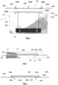
- FIGS. 1 to 6 illustrate a container 1 according to the invention for the cultivation of shellfish which, in this example, is in the form of an oyster bag 1.
- FIG 1 illustrates a partially exploded view of a pocket 1 according to the present disclosure.
- This pocket 1 has a frame 10 and a casing 11.
- the figure 4 shows that the frame 10 comprises a hanger 100 and a suspension axle 105.
- the frame 10 is made of metal, and more preferably still of stainless steel so as to withstand marine stresses/conditions.
- An envelope 11 (visible on the figure 1 ) made of flexible mesh is arranged on/over the frame 10 so as to form a volume, or space, 12 for receiving the oysters.
- the envelope 11, which therefore at least partially covers the frame 10, is preferably made of recycled and/or recyclable plastic.
- This material has a relatively low cost and high resistance to marine conditions. In addition, this material has been used for many years to manufacture oyster bags and has demonstrated that it is perfectly suited/compatible with oyster farming.
- the mesh sizes of the enclosure mesh 11 are selected according to the growth, i.e. the size, of the oysters.
- the oyster bags must be successively changed throughout the growth of the oysters to adapt the dimensions of the mesh of the flexible envelope 11 to the size of the oysters.
- the oyster bags are changed three times during the growth of the oysters.
- the casing 11 has, before its assembly with the frame 10, at least one of its two open ends.
- the casing 11 is in the form of a tube open at least at one of its ends.
- both ends of the envelope 11 are open, it is then necessary to close/condemn one of the ends so as to form the bottom of the envelope 11.
- This closure can be obtained by using UV-resistant clamping collars, or by gluing or welding, for example.
- the open, or openable, end of the flexible envelope 11 has reversible closing means 111 of the flexible envelope 11.
- the flexible envelope 11 comprises hooks 112 mounted on an elastic band 113. More precisely, a first end of the elastic band 113 is secured to the outer wall of the envelope 11 while the other end of the elastic band carries a hook 112 intended to cooperate with a hole in the mesh of the flexible envelope 11 to allow the walls of the envelope 11 to be brought into contact at this open end and hermetically close the end of the envelope 11 (in the sense that the oysters cannot exit the receiving space 12 in an undesirable manner).
- the flexible envelope 11 comprises three closing hooks 112.
- the flexible envelope 11 may comprise a flap (not illustrated) provided with the elastics 113 and the hooks 112 described above. In this way, it is possible to cover the open end of the envelope 11 with the flap and to maintain/lock the position of the flap on the opening of the envelope 11 by means of the hooks 112 and the elastics 113.
- the flap makes it possible to hermetically close the end of the envelope 11 (in the sense that the oysters cannot escape from the receiving space 12 in an undesired manner).
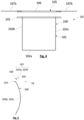
- the frame 10 is illustrated in detail and in different views on the Figures 3 to 5 . As previously indicated, it comprises a hanger 100 and a suspension axle 105 which are secured together during assembly of the pocket 1.
- the hanger 100 comprises a substantially rectilinear base 101 which has, in this example, a substantially arc-shaped section (as illustrated in the figure 5 ).
- This base 101 extends substantially over the entire length of the flexible envelope 11 when these elements are assembled (see figure 1 ).
- the base 101 has a length of approximately 65 cm.
- This arc-shaped section makes it possible to adapt to the shape of the pocket 1 at this location of the pocket 1 and to avoid pinching the flexible envelope 11, so as to limit the risks of tearing the latter.
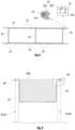
- this element 102 comprises a central upright 102a, extending substantially parallel to the base 101, having two ends from which two lateral uprights 102b, 102c extend substantially perpendicularly.
- the lateral uprights 102b, 102c therefore connect the central upright 102a to the base 101 and substantially form a square (according to the front view of the hanger illustrated in the figure 4 ).
- the uprights 102a, 102b and 102c have a length of approximately 50 cm and the U-shaped element 102 is substantially centered relative to the base 101.
- the side uprights 102b, 102c have a profile (according to the side view of the figure 5 in particular) arched/curved which allows the pocket 1 to have its volume when the flexible envelope 11 is assembled with the hanger 100. It is therefore possible to choose/select the desired radius of curvature for the side uprights 102b, 102c in order to define the dimensions of the space 12 for receiving the oysters.
- the side uprights 102b, 102c are curved so as to obtain a curve approximately 8 cm high.
- Such a hanger 100 arranged inside the flexible envelope 11, allows the bag 1 to always keep its “locker” shape, that is to say to keep a curved shape providing a space 12 for receiving the oysters, when it is loaded and closed.
- the bag 1 once the bag 1 is empty, it is possible to flatten/crush the openable side in order to allow the flexible envelope 11 to flatten/crush against the hanger 100.
- the entire bag 1 flattens against the hanger 100, so as to follow the shape of the hanger 100 and provide an optimized footprint. In this way, when the bags 1 are not used at sea, they can be stacked so as to have a limited footprint allowing a very significant saving of space when storing them. on the ground.
- the suspension axis 105 has a central portion 106 which is substantially rectilinear and which has a section in the shape of an arc of a circle (as illustrated in the figure 5 ) corresponding to the base 101.
- This central part 106 is substantially identical to the base 101, and therefore has substantially the same length as the base 101 (i.e. approximately 65 cm in the example illustrated).
- the central part 106 and the base 101 have a substantially U-shape.
- the central portion 106 carries, at each of its ends, a circular rod 107a, 107b forming the axis of rotation 105 of the pocket 1. More precisely, in the example illustrated, the circular rods 107a, 107b are fixed at the ends, on the upper surface of the central portion 106 (i.e. the surface opposite the inside of the pocket 1). In this example, the circular rods 107a, 107b have a length of approximately 30 cm and protrude by approximately 23 cm relative to the central portion 106.
- the circular rods 107a, 107b preferably extend in an offset axis parallel to the axis of the central portion 106.
- This offset that is to say the fact that the axis of the circular rods 107a, 107 is eccentric/offset allows the bag 1 to rotate/pivot, relative to the suspension table, upwards and to always replace itself on the same side.
- the rotation of the bags is better controlled/controlled even in the event of storms. The mortality of the oysters is therefore significantly reduced.
- the circular rods 107a, 107b are welded to the central portion 106.
- Other methods of securing can nevertheless be envisaged, such as screwing or riveting for example.
- the central portion 106 would receive and hold the circular rods 107a and 107b, made of stainless steel, forming the axis of rotation 107.
- the axis of rotation 107 could itself be made of plastic, with for example a system for attaching the container 1 to the suspension support which would be different.
- the axis of rotation formed by the suspension axis 105 is therefore here fixed on the pocket (and not on the table).
- this axis is slightly offset relative to the outer surface of the pocket 1, which allows the pocket 1 to always descend on the same side when the sea ebbs. In this way, the pocket 1 rotates on an axis integrated into the pocket, or carried by the pocket. Obviously, the implementation of this axis does not hinder the filling and emptying of the pocket 1.
- the hanger 100 and the suspension axis 105 are secured in this example by reversible fixing means 108 so as to facilitate the assembly and disassembly of the casing 11 with the metal frame 10 as well as the replacement of the flexible casing 11 during the growth of the oysters, for example.
- the fixing means 108 are in the form of holes 108a formed in the central portion 106 of the suspension axis 105 and the base 101 of the hanger 100. These holes 108a are intended to cooperate with screws and nuts (conventional nuts or lock nuts) for fixing 108b.
- the central portion 106 of the suspension axle 105 and the base 101 of the hanger 100 have three holes 108a cooperating with three pairs of fixing screws and nuts 108b. They are, in this example, located in the center of the central portion 106 and approximately 2 cm from the ends of the central portion 106.
- the circular rods 107a, 107b also carry thrust washers 109 which make it possible to maintain the position of the pocket 1 relative to the suspension table (described in the remainder of this description).
- these thrust washers 109 allow optimal centering of the pocket 1 and prevent it from moving in translation relative to the suspension table, even in the event of storms for example.
- These thrust washers 109 are for example welded to the circular rods 107a, 107b, at a determined distance from the free end of the circular rods 107a, 107b to allow optimal centering. In this example, the thrust washers 109 are welded approximately 7.5 cm from the free end.
- the oyster bag 1 carries at least one float 13, which is preferably removable (as shown by the figures 1 , 9 And 11 ).
- the float(s) 13 are arranged on the same face so as to ensure rotation and descent of the pocket 1 always in the same direction/on the same side.
- the pocket 1 only carries a single float 13 extending substantially over a length identical to the hanger 100, as visible in the figure 1 .
- the float 13 is located on the lower half of the pocket 1 (as seen from the figure 1 ), that is to say as close as possible to the ground or opposite the suspension axis 105. This ensures optimal rotation of pocket 1 during tides.
- the float 13 is fixed on the outer surface of the flexible envelope 11 of the bag 1, and preferably on the side of the hanger 100, so as to allow the oysters to roll freely inside the bag 1.
- the float 13 is fixed to the outside of the envelope 11 by a hook mechanism 131 and elastic straps 132.
- This mechanism makes it possible to simply and reliably fix the float 13 to the envelope 11. Nevertheless, it is obviously understood that other solutions can be envisaged for fixing the float 13, without departing from the general principle of the invention.
- the float 13 is preferably removable, such that it is possible to attach it or not to the bag 1 depending on the time of year in order to optimize the growth of the shellfish.
- the float 13 rotates the bag 1 around its suspension axis 105. This rotation of the bag 1 therefore makes it possible to move the oysters, without human intervention, twice a day during periods of high water on the breeding grounds and every day on the fattening grounds located further ashore.
- the oyster bag 1 according to the invention makes it possible to no longer have to manually shake/turn the oyster bags 1, unlike the technique traditionally used.
- the oyster bag 1 of the invention has dimensions that comply with the regulations in force, that is to say that the oyster bags of the invention fall within the framework imposed by the maritime structures diagram. More precisely, the diagram of the structures of marine culture farms in the Manche department (France) stipulates that the bags must comply with the following dimensions: 1 mx 0.50 x 0.20 or 0.1 m 3 . Other dimensions are possible/authorized, provided that the volume indicated above is respected. It should be noted that the diagram of the structures of marine culture farms in Loire-Atlantique only has one indication, namely "1 meter type bag".
- the bag 1 has, in this example, a length of approximately 93 cm and a width of approximately 50 cm.
- the thickness of the bag, at its center or at its greatest thickness, is between 12 and 16 cm once the bag 1 is assembled.
- the pocket 1 has a length of between 70 cm and 120 cm, a width between 40 and 70 cm and a thickness between 12 and 40 cm.
- pocket 1 having a float (described below) could have a length of 0.70 m, a width of 0.40 m and a thickness of 0.35 m, i.e. a volume of approximately 0.1 m3 corresponding to the diagram of the Channel structures.
- Such a bag 1 allows, for fattening oysters, to cultivate with a density of between approximately 120 and 130 units per bag 1.
- the density is between 180 to 220 units per bag 1.
- the density is between 350 to 400 units per bag 1.
- the envelope 11 has, for example, before assembly with the frame 10, a length of approximately 115 cm and a width of approximately 53 cm.
- the bag 1 according to the disclosure makes it possible to maintain a yield at least as high as with bags according to the traditional technique, while significantly improving the shape and quality of the oysters.
- the bag of the present disclosure also makes it possible to significantly reduce the arduousness of the shaking work since the bag rotates automatically/naturally thanks to the tides.
- the bag 1 in accordance with the disclosure is suitable for all stages of use of traditional oyster bags, i.e. filling/emptying and placing on storage areas while awaiting sorting of the oysters, for example.
- bag 1 in accordance with the disclosure allows, depending on the size of the mesh used, the breeding of oysters throughout the cycle, that is to say from spat to refining.
- Such a rigid locker 1' may also directly carry a rotation axis 105 as described above.
- the rigid locker 1' may also carry a float 13 as described above.
- the rotation axis 105 and the float 13 have the same structures, characteristics and advantages as those presented in relation to the flexible bag 1 described above and are therefore not described again.
- the invention also relates to a suspension support 2, hereinafter called suspension table 2, which is configured to receive and hold in position a plurality of containers 1, 1' such as the flexible bag 1 or the rigid locker 1' described above.
- the suspension table 2 is also configured to allow the suspension axis 105 of the containers 1, 1' to pivot relative to the table 2, so as to allow an automatic/natural rotation movement of the container 1, 1' relative to the suspension table 2 during tides, in particular. To do this, the suspension table 2 does not have a crossbar in the vicinity of the containers 1, 1' suspended on the suspension table 2 which could prevent/hinder the rotation of the containers 1, 1'.
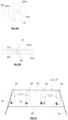
- a first example of suspension table 2 is illustrated on the figures 7 And 8 .
- a hanging table 2 according to the disclosure comprises at least four legs 21 arranged in at least two parallel lines, or rows, 211a, 211b.
- the hanging table 2 comprises six legs arranged in two rows of three legs 21 spaced evenly apart in each row.
- the six legs 21 are arranged in three pairs of legs 21.
- the legs 21 of the same pair are connected by a crosspiece 26 thus forming a U whose base on the ground (formed by the crosspiece 26) is preferably less wide (for example 30 cm) than the spacing between the free end of the legs 21 of the same pair of legs.
- the free end of the legs 21 of the same pair are spaced apart by a distance of approximately 97 to 100 cm.
- the suspension table 2 has a flared shape allowing the tables 2 to be stacked during storage on the ground, so as to limit their bulk, in particular.
- reinforcement bars 25 can be used to connect the feet 21 of the same row 211a, 211 in order to prevent any swinging of the suspension table 2 at sea.
- the reinforcement bars 25 are arranged at a distance from the upper end of the feet 21 at least equal to the width Ig (visible on the figure 6 ) of a container 1, 1' and in particular of an oyster bag 1 or of a rigid basket 1' as described above. This distance ensures that the container 1, 1' can pivot freely relative to the suspension table 2 and makes it possible to facilitate the operations of lifting the containers 1, 1' for example using a lifting machine (not described).
- each row 211a, 211b of legs 21 carries an upper bar 22.
- the suspension table 2 has, in this example, two upper bars 22 extending parallel.
- the upper bars 22 comprise receiving means 23 for at least one container 1, 1' on the suspension table 2. More specifically, the upper bars 22 comprise a plurality of receiving means 23 preferably arranged with a constant/regular spacing along each upper bar 22.
- the receiving means 23 are arranged at corresponding positions on each of the upper bars 22 such that the receiving means 23 are arranged facing each other on the upper bars 22 and form pairs of receiving means 23. Thus, each pair of receiving means 23 can receive and hold in position a container 1.
- the receiving means 23 are more specifically configured to receive the suspension axis 105 of a container 1, 1' while allowing rotation of the suspension axis 105 within the receiving means 23.
- receiving means 23 of the suspension axis 105 of the container 1, 1' makes it possible to easily fix, at sea, the oyster containers 1, 1' without using the elastic or rubber bands used in at least some of the techniques of the prior art. These receiving means 23 also make it possible to eliminate or at least limit the risks of loss of the containers 1, 1' at sea.
- the example illustrated on the figure 8 shows a first embodiment in which the receiving means 23 are in the form of hooks 231 in the shape of a lying U which are fixed on the upper bars 22.
- the hooks are made of metal, and more preferably still of stainless steel.
- each upper bar 22 carries eight hooks 231 welded and spaced about 55 cm apart along the upper bar 22.
- the illustrated hanging table 2 is capable of supporting eight containers 1, 1' spaced about 55 cm apart.
- the containers 1, 1' located at the end of the hanging table 2 are separated from the containers 1, 1' of the next hanging table 2 by about 57 cm.
- V-shaped hooks 231 pointing upwards, which are particularly suitable for the automation/mechanization of container removal.
- the hooks 231 are all oriented in the same direction and the same sense in order to allow mechanization/automation of the installation/loading and the uninstallation/unloading of the containers 1, 1' on the suspension table 2.
- the suspension table 2 also comprises first locking means 24 of the support axis 105 in the locking means 23 in order to prevent the container 1, 1' from being removed involuntarily or undesirably from the suspension table 2.
- the first reversible locking means 24 are in the form of a bore 241 formed through the hook 231 and a pin 242, preferably made of stainless steel, configured to cooperate with said bore 241.
- the hooks 231 are welded in a manner slightly offset relative to the longitudinal axis of the upper bar 22 in order to ensure easy insertion of the pin 242 into the bore, i.e. without being hindered by the upper bar 22, in particular.
- This relatively simple technique to implement makes it possible to reliably maintain the container 1, 1' on the suspension table 2.
- Reversible locking means are understood to mean locking means that can be moved at least between a locked position and an unlocked position.
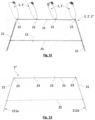
- FIG 13 illustrates another example of a 2" suspension bracket also in the form of a suspension table.
- this 2" suspension table comprises four feet 21 arranged in two rows, 211a, 211b parallel and spaced evenly in each row.
- the feet 21 are inclined.
- the suspension table 2" has a flared shape allowing the tables 2 to be stacked during storage on the ground, so as to limit their bulk, in particular.
- the angle of inclination of the feet 21 is selected to obtain an offset of approximately 26 cm relative to the vertical of the end of the upper bars 22 in order to allow optimal and easy positioning of the next/adjacent table of the feet-to-feet type. This particular inclination makes it possible to directly obtain the desired distance of approximately 55 cm between the receiving means 23 of the rotation axes 105 of the containers 1, 1' of two adjacent tables.
- the 2" hanging table is suitable for holding four 1" containers. This allows the containers to be easily handled by a single operator.
- the 2.2" suspension tables shown on the figures 7 , 8 and 14 are for example made of metal, and preferably of iron.
- the legs 21, the upper bars 22, the reinforcement bars 25 and the crosspieces 26 are made of iron and are welded together.
- Such a suspension table 2, 2" entirely made of metal is adaptable to all types of terrain, that is to say it can be installed on soft ground, such as sand or mud, and on hard ground, such as on rocky ground, for example.
- This suspension table 2, 2" can for example be fixed to the ground in a manner identical to traditional tables, that is to say by iron stakes having substantially a shape of "1" (one) or "L".
- This shape of the stakes makes it possible to avoid having to use rubber to fix the stakes to the legs 21 of the suspension table 2.
- the angle/inner corner of the “1” or the “L” is positioned at the junctions between the legs 21 and the crosspieces 26 or the reinforcement bars 25.
- suspension table 2 is easily handled when installing on parks. Indeed, it has a lower weight than the tables traditionally used, thus making the work of the operators less physically difficult.
- the suspension table 2.2" is made of wood and iron. More specifically, such a suspension table 2.2" comprises legs 21, in the form of wooden stakes, driven into the ground at regular intervals and in at least two rows 211a, 211b, in accordance with the description above.
- the wood used is preferably an exotic rot-proof wood known for its longevity in a marine environment.
- the wooden feet 21 are preferably implanted vertically in the substrate and adjusted in height (for example between 0.90 m and 1.40 m) according to the parks and the tidal coefficients of these parks.
- the two rows 211a, 211b of feet 21 are spaced approximately 1 m apart and the feet of the same row 211a, 211b are spaced approximately 1.10 m apart.
- upper iron bars 22 are fixed (for example by bolting) to the free end of the feet 21 and carry means 23 for receiving the suspension axis 105 of the oyster containers 1.
- the receiving means 23 can be presented, as previously, in the form of hooks 231 in a lying U shape (cf. figure 8 ) or V-shaped (facing upwards), said welded hooks being on the upper bars 22.
- First locking means 24 (for example identical to the holes 241 and the pins 242) can also be implemented.
- the reinforcement bars 25 and the crosspieces 26 are optional.
- Such a 2.2" suspension table combining wooden legs 21 and iron upper bars 22, is particularly suitable for installation on soft soils, such as sand or mud, for example. Indeed, such wooden legs can only be planted in soils containing little or no rock. Cultivation parks implemented on soils consisting mainly of rock will therefore not be able to accommodate this type of table.
- the suspension table 2, 2" comprises feet 21, in the form of wooden stakes, driven into the ground at regular intervals and in at least two rows 211a, 211b, in accordance with the description above.
- upper bars 22 (this time made of wood) are fixed to the free end of the feet 21 and carry means 23 for receiving the suspension axis 105 of the containers 1, 1'.
- the receiving means 23 may be in the form of U-shaped hooks 231 (made of stainless steel for example) fixed by screwing onto the upper bars 22.
- First locking means 24 (for example identical to the holes 241 and the pins 242) may also be implemented.
- the reinforcing bars 25 and the crosspieces 26 are also optional.
- the wood used is preferably an exotic rot-proof wood known for its longevity in a marine environment.
- a 2.2" suspension table made entirely of wood, is particularly suitable for installation on soft ground, such as sand or the vase, for example.
- the suspension support is in the form of another suspension table 2' made of wood and plastic (or one of its derivatives, hereinafter grouped under the general term "plastic") having sufficient rigidity to support the oyster containers 1, 1'.
- this suspension table 2' comprises feet 21, in the form of wooden stakes, driven into the ground at regular intervals and in at least two rows 211a, 211b, in accordance with the description above.
- each of the upper bars 22' is made up of two half-bars 221a, 221b (illustrated in the Figures 10a and 10b ) substantially identical (but may have a different thickness for example).
- the half-bars 221a, 221b are fixed to the free end of the feet 21 by a fixing screw 223 and a washer (not visible but for example made of stainless steel).
- the half-bar 221a in contact with the wooden foot 21 has a hole in which the fixing screw 223 is inserted, preferably made of stainless steel, which is then screwed into the foot 21, as illustrated in the figure 10a . It is obviously understood that other solutions for fixing the upper bars 22' on the feet 21 are possible without departing from the general principle of the invention.
- the half-bars 221a, 221b have, on their faces located opposite each other, slots, or notches, 222 which are for example machined in the shape of a semicircle or a hook open upwards.
- These notches 222 are arranged regularly (for example every 55 cm) and are located at corresponding positions along the half-bars 221a, 221b so that, when the half-bars 221a, 221b are assembled, the notches 222 together form a circular orifice configured to receive and hold the suspension axis 105 of an oyster container 1, 1'.
- the notches 222 of the half-bars 221a, 221b form the receiving means 23 of the oyster containers 1, 1'.
- the oyster containers 1, 1' are suspended by their suspension axes 105 between the two rows 211a, 211b of feet 21 and the upper bars 22'.
- second reversible locking means 27 can be implemented. To do this, it is possible to provide holes 271 passing through the two half-bars 221a, 221b which are configured to cooperate with, for example, a fixing bolt 272.
- the fixing bolt 272 comprises a stainless steel wing nut, a stainless steel washer, a stainless steel threaded rod, a second stainless steel washer and a stainless steel nut.
- the fixing bolt 272 can be replaced by a secure pin, a padlock or any other device for locking the half-bars 221a, 221b together, without departing from the general principle of the invention.
- the reinforcement bars 25 and the crosspieces 26 are optional.
- Such a 2-section suspension table combining wooden legs and plastic top bars, is particularly suitable for installation on soft ground, such as sand or mud, for example.
- a 2' suspension table of this type has a significantly higher longevity/service life than known suspension tables. In fact, these tables allow a service life of approximately 20 to 30 years to be achieved.
- the plastic material used for the upper bars 22' allows only very little algae and shellfish to cling.
- the plastic is also selected to be easily recyclable and to have very low adhesion so that the suspension axis 105 made of stainless steel containing 1, 1' can rotate easily and with almost no wear. Thus, the environmental impact of such a 2' suspension table is optimized.
- the suspension table 2 does not have high crossbars so as to allow the passage of a machine for loading and unloading the containers on a towed trailer or on a boat, for example, so as to mechanize/automate the operations of loading/unloading the shellfish containers.
- FIG 11 illustrates an example of a suspension table 2, 2', 2" according to the invention showing the containers 1, 1' according to the invention in the rest position, that is to say standing substantially vertically.
- This rest position is the one that the containers 1, 1' can take when the tide is low, for example.
Landscapes
- Life Sciences & Earth Sciences (AREA)
- Environmental Sciences (AREA)
- Marine Sciences & Fisheries (AREA)
- Zoology (AREA)
- Animal Husbandry (AREA)
- Biodiversity & Conservation Biology (AREA)
- Farming Of Fish And Shellfish (AREA)
- Cultivation Receptacles Or Flower-Pots, Or Pots For Seedlings (AREA)
Applications Claiming Priority (1)
| Application Number | Priority Date | Filing Date | Title |
|---|---|---|---|
| FR2300798A FR3145258B1 (fr) | 2023-01-27 | 2023-01-27 | Contenants a coquillages et supports de suspension correspondants |
Publications (1)
| Publication Number | Publication Date |
|---|---|
| EP4417048A1 true EP4417048A1 (de) | 2024-08-21 |
Family
ID=85937434
Family Applications (1)
| Application Number | Title | Priority Date | Filing Date |
|---|---|---|---|
| EP24154234.9A Withdrawn EP4417048A1 (de) | 2023-01-27 | 2024-01-26 | Behälter aus schalentieren und entsprechende aufhänger |
Country Status (2)
| Country | Link |
|---|---|
| EP (1) | EP4417048A1 (de) |
| FR (1) | FR3145258B1 (de) |
Citations (10)
| Publication number | Priority date | Publication date | Assignee | Title |
|---|---|---|---|---|
| FR2576484A1 (fr) * | 1985-01-30 | 1986-08-01 | Moxham Wayne | Procede et appareil pour l'elevage de mollusques |
| EP0681783A1 (de) * | 1994-05-11 | 1995-11-15 | Les Vergers De L'atlantique | Käfig zum Züchten von Schalentieren, insbesondere von Austern |
| EP1266567A2 (de) * | 2001-06-13 | 2002-12-18 | Anthony John Schutz | Verschluss für Austernsack |
| FR2859877A1 (fr) * | 2003-09-19 | 2005-03-25 | Bmts Sa | Table et procede d'elevage de coquillages |
| FR2883700A1 (fr) * | 2005-03-31 | 2006-10-06 | Yad Marine Sarl | Dispositif d'accrochage d'une cage de conchyliculture, notamment d'ostreiculture, a un support essentiellement tubulaire |
| FR2896664A1 (fr) * | 2006-01-31 | 2007-08-03 | Bmts Sarl | Machine (100) a collecter des poches ostriecoles (p) |
| FR2900027A1 (fr) * | 2006-04-21 | 2007-10-26 | Vergers De L Atlantique | Dispositif de support d'au moins une poche d'elevage de coquillages |
| CN106900615A (zh) * | 2017-03-21 | 2017-06-30 | 山东省海洋生物研究院 | 一种可调节网眼大小的贝类养殖设备 |
| US20180288980A1 (en) * | 2015-12-08 | 2018-10-11 | Norman Boyle | Oyster farming apparatus and methods |
| WO2019081184A1 (fr) * | 2017-10-27 | 2019-05-02 | Genocean | Dispositif d'élevage en mer d'animaux d'aquaculture |
-
2023
- 2023-01-27 FR FR2300798A patent/FR3145258B1/fr active Active
-
2024
- 2024-01-26 EP EP24154234.9A patent/EP4417048A1/de not_active Withdrawn
Patent Citations (10)
| Publication number | Priority date | Publication date | Assignee | Title |
|---|---|---|---|---|
| FR2576484A1 (fr) * | 1985-01-30 | 1986-08-01 | Moxham Wayne | Procede et appareil pour l'elevage de mollusques |
| EP0681783A1 (de) * | 1994-05-11 | 1995-11-15 | Les Vergers De L'atlantique | Käfig zum Züchten von Schalentieren, insbesondere von Austern |
| EP1266567A2 (de) * | 2001-06-13 | 2002-12-18 | Anthony John Schutz | Verschluss für Austernsack |
| FR2859877A1 (fr) * | 2003-09-19 | 2005-03-25 | Bmts Sa | Table et procede d'elevage de coquillages |
| FR2883700A1 (fr) * | 2005-03-31 | 2006-10-06 | Yad Marine Sarl | Dispositif d'accrochage d'une cage de conchyliculture, notamment d'ostreiculture, a un support essentiellement tubulaire |
| FR2896664A1 (fr) * | 2006-01-31 | 2007-08-03 | Bmts Sarl | Machine (100) a collecter des poches ostriecoles (p) |
| FR2900027A1 (fr) * | 2006-04-21 | 2007-10-26 | Vergers De L Atlantique | Dispositif de support d'au moins une poche d'elevage de coquillages |
| US20180288980A1 (en) * | 2015-12-08 | 2018-10-11 | Norman Boyle | Oyster farming apparatus and methods |
| CN106900615A (zh) * | 2017-03-21 | 2017-06-30 | 山东省海洋生物研究院 | 一种可调节网眼大小的贝类养殖设备 |
| WO2019081184A1 (fr) * | 2017-10-27 | 2019-05-02 | Genocean | Dispositif d'élevage en mer d'animaux d'aquaculture |
Also Published As
| Publication number | Publication date |
|---|---|
| FR3145258B1 (fr) | 2025-05-09 |
| FR3145258A1 (fr) | 2024-08-02 |
Similar Documents
| Publication | Publication Date | Title |
|---|---|---|
| CA1188098A (fr) | Nasses pour crustaces | |
| EP3490372B1 (de) | Vorrichtung zur aufzucht von aquakulturtieren auf dem meer | |
| EP3700332B1 (de) | Vorrichtung zur aufzucht von aquakulturtieren auf dem meer | |
| FR3003128A1 (fr) | Portique pour l'elevage d'huitres | |
| FR2597716A1 (fr) | Une methode et un dispositif de culture et/ou d'elevage des mollusques et crustaces tels que les benitiers. | |
| EP0681783A1 (de) | Käfig zum Züchten von Schalentieren, insbesondere von Austern | |
| FR3054952B1 (fr) | Dispositif d'elevage en mer d'animaux d'aquaculture | |
| EP4417048A1 (de) | Behälter aus schalentieren und entsprechende aufhänger | |
| FR2956795A1 (fr) | Support pour poches a coquillages | |
| EP3629716A1 (de) | Vorrichtung und verfahren für molluskenfarm | |
| FR2594434A1 (fr) | Dispositif et procede de production d'humus par lombricompostage | |
| EP3700331B1 (de) | Vorrichtung zur aufzucht von aquakulturtieren auf dem meer | |
| FR3064884B1 (fr) | Vivier pour organismes aquatiques vivants | |
| WO2019081740A1 (fr) | Dispositif d'élevage en mer d'animaux d'aquaculture | |
| FR2953367A1 (fr) | Poche tambour d'elevage d'huitres | |
| FR2841741A1 (fr) | Dispositif pour l'elevage de mollusques filtreurs en suspension en pleine eau | |
| EP4512242A1 (de) | Vorrichtung zur schalentierzucht und verfahren dafür | |
| EP3993620B1 (de) | Gehäuse, säule und verfahren zur züchtung von muscheln | |
| FR2479881A1 (fr) | Procede et dispositif pour realiser une couverture de bassin | |
| FR2887400A1 (fr) | Poche de conchyliculture incluant des moyens de rigidification repliables | |
| FR2800047A1 (fr) | Chassis de support pour maintenir un conteneur souple en position ouverte de remplissage | |
| FR3133289A1 (fr) | Dispositif et procédé d’élevage de mollusques | |
| FR3166035A1 (fr) | Dispositif de collecte d’algues en mer à efficacité améliorée | |
| FR2980953A1 (fr) | Dispositif support de bacs a plantes mobiles formant jardin d'ornementation | |
| FR2830720A1 (fr) | Ensemble bifonctionnel servant de bac a plantes |
Legal Events
| Date | Code | Title | Description |
|---|---|---|---|
| PUAI | Public reference made under article 153(3) epc to a published international application that has entered the european phase |
Free format text: ORIGINAL CODE: 0009012 |
|
| STAA | Information on the status of an ep patent application or granted ep patent |
Free format text: STATUS: THE APPLICATION HAS BEEN PUBLISHED |
|
| AK | Designated contracting states |
Kind code of ref document: A1 Designated state(s): AL AT BE BG CH CY CZ DE DK EE ES FI FR GB GR HR HU IE IS IT LI LT LU LV MC ME MK MT NL NO PL PT RO RS SE SI SK SM TR |
|
| STAA | Information on the status of an ep patent application or granted ep patent |
Free format text: STATUS: THE APPLICATION IS DEEMED TO BE WITHDRAWN |
|
| 18D | Application deemed to be withdrawn |
Effective date: 20250222 |