EP3700331B1 - Vorrichtung zur aufzucht von aquakulturtieren auf dem meer - Google Patents
Vorrichtung zur aufzucht von aquakulturtieren auf dem meer Download PDFInfo
- Publication number
- EP3700331B1 EP3700331B1 EP18789452.2A EP18789452A EP3700331B1 EP 3700331 B1 EP3700331 B1 EP 3700331B1 EP 18789452 A EP18789452 A EP 18789452A EP 3700331 B1 EP3700331 B1 EP 3700331B1
- Authority
- EP
- European Patent Office
- Prior art keywords
- enclosure
- rearing
- breeding
- enclosures
- framework
- Prior art date
- Legal status (The legal status is an assumption and is not a legal conclusion. Google has not performed a legal analysis and makes no representation as to the accuracy of the status listed.)
- Active
Links
Images


Classifications
-
- A—HUMAN NECESSITIES
- A01—AGRICULTURE; FORESTRY; ANIMAL HUSBANDRY; HUNTING; TRAPPING; FISHING
- A01K—ANIMAL HUSBANDRY; AVICULTURE; APICULTURE; PISCICULTURE; FISHING; REARING OR BREEDING ANIMALS, NOT OTHERWISE PROVIDED FOR; NEW BREEDS OF ANIMALS
- A01K61/00—Culture of aquatic animals
- A01K61/60—Floating cultivation devices, e.g. rafts or floating fish-farms
- A01K61/65—Connecting or mooring devices therefor
-
- A—HUMAN NECESSITIES
- A01—AGRICULTURE; FORESTRY; ANIMAL HUSBANDRY; HUNTING; TRAPPING; FISHING
- A01K—ANIMAL HUSBANDRY; AVICULTURE; APICULTURE; PISCICULTURE; FISHING; REARING OR BREEDING ANIMALS, NOT OTHERWISE PROVIDED FOR; NEW BREEDS OF ANIMALS
- A01K61/00—Culture of aquatic animals
- A01K61/50—Culture of aquatic animals of shellfish
- A01K61/54—Culture of aquatic animals of shellfish of bivalves, e.g. oysters or mussels
- A01K61/55—Baskets therefor
-
- Y—GENERAL TAGGING OF NEW TECHNOLOGICAL DEVELOPMENTS; GENERAL TAGGING OF CROSS-SECTIONAL TECHNOLOGIES SPANNING OVER SEVERAL SECTIONS OF THE IPC; TECHNICAL SUBJECTS COVERED BY FORMER USPC CROSS-REFERENCE ART COLLECTIONS [XRACs] AND DIGESTS
- Y02—TECHNOLOGIES OR APPLICATIONS FOR MITIGATION OR ADAPTATION AGAINST CLIMATE CHANGE
- Y02A—TECHNOLOGIES FOR ADAPTATION TO CLIMATE CHANGE
- Y02A40/00—Adaptation technologies in agriculture, forestry, livestock or agroalimentary production
- Y02A40/80—Adaptation technologies in agriculture, forestry, livestock or agroalimentary production in fisheries management
- Y02A40/81—Aquaculture, e.g. of fish
Definitions
- the invention generally relates to devices for farming shellfish at sea and more particularly oysters.
- the breeding areas are demarcated exclusively in the intertidal zone, allowing access at low tide to the personnel responsible for stirring the enclosures.
- These enclosures are generally plastic mesh bags, placed on tables made of steel bars anchored to the beach.
- the oysters ensure their proper growth, but very rarely achieve a quality of flesh equivalent to that sought by the informed consumer, accustomed to eating shucked oysters.
- the uncovered zone that is to say the intertidal zone, is characterized by the strength of the waves, itself a function of the exposure of the coastline concerned to the wind and the offshore swell.
- the waves On rare sites, it is thus possible, due to particularly powerful and regular mixing by the waves, to obtain not only oysters sufficiently rolled in the breeding bags so that their shells are eroded, rounded and very hollow, but also an exceptional meat content.
- These oysters are called "super special".
- the phenomenon involved is simple: the oyster, when its feeding capacity is satisfied, always prioritizes, up to a certain age (3 years), the allocation of energy to shell growth to the detriment of fattening.
- This quality can be quantified as a 60% filling rate of the mantle cavity after opening and 10 minutes of draining.
- This combination of quality of shape and high flesh content constitutes the very top-of-the-range product which, consumed raw, is highly appreciated by consumers in all countries of the world.
- the enclosures are suspended from horizontally stretched cables, or under steel bars carried by oyster tables. They are very mobile, and are therefore likely to transfer to the oysters they contain the movement imparted by ocean currents and waves of lesser amplitude than those necessary to stir the oysters in the fixed enclosures.
- enclosures are very fragile. They are effective for stirring oysters in moderately severe conditions (ocean current, swell, etc.) but cannot withstand the severe conditions accepted by fixed enclosures. They are therefore not usable. only in a protected, semi-lagoon environment, and can therefore only be used in a very small proportion of oyster farming sites for French-style oyster production.
- FR 2 576 484 proposes adding a float to the outside of the enclosure. This way, the enclosure turns over between high tide, during which it floats, and low tide, during which it hangs. It is clear that this turning allows for better mixing of the oysters, particularly at the time of emergence at low tide.
- the document FR 2 908 213 describes a device for farming shellfish at sea in accordance with the preamble of claim 1.
- the invention aims to propose a sea farming device which provides good mixing and which is more easily adaptable.
- the invention relates to a device for rearing aquaculture animals at sea which are shellfish according to claim 1.
- the limiting device limits the vertical amplitude of the movement, which allows the breeder to adapt the system to the hydraulic conditions prevailing in the breeding area and to the seasonality of his breeding.
- the limiter device also allows the amplitude and duration of agitation of the shellfish to be adjusted, in order to regulate the desired effect on the shellfish.
- the device may further have one or more of the features of claims 2 to 9.
- the invention relates to a device for rearing aquaculture animals at sea.
- These animals are shellfish, and are more particularly oysters.
- the shellfish are any kind of bivalve such as clams, mussels or any other type of shellfish.
- This device is intended for breeding at sea. This breeding can be carried out off the coast or in straits, estuaries or rias, or even in ponds communicating with the sea or in any other suitable location.
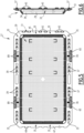
- the breeding device comprises a plurality of breeding enclosures 5, each arranged between two metal bars 17.
- Each breeding enclosure 5 has a lower base 23, which is substantially flat.
- the length and width are greater than five times the spacing, more preferably greater than ten times the spacing.
- the breeding enclosure has a length of around 1 meter, a width of around 500 mm, and a height of around 50 mm.
- the two half-enclosures 27 are identical to each other.
- They are preferably made of a plastic material, for example polypropylene.
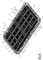
- Each half-enclosure 27 comprises a substantially flat part 29 defining the upper bottom or the lower bottom depending on the case, an annular flat edge 31 surrounding the flat part 29, and a closed-contour wall 33 connecting the flat part 29 to the flat edge 31 ( Figures 5 and 6 ).
- the closed-contour wall 33 connects an outer edge of the flat portion 29 to an inner edge of the flat edge 31.
- the flat edge 31 forms a collar, extending outwardly from the wall 33.
- the flat edge 31 lies in a plane parallel to the flat part 29, defining the contact plane between the two half-enclosures when they are assembled to form the breeding enclosure.
- the flat portion 29 and the side wall 33 are pierced by multiple unreferenced openings, small enough so that the aquaculture animals cannot escape from the breeding enclosure, but large enough to allow circulation of water between the inside and the outside of the breeding enclosure.
- the flat part 31 and the side wall 33 are reinforced by ribs 34.
- the two half-enclosures 27 can be nested inside each other. This makes it possible to stack a large number of half-enclosures and store them in a small volume.
- the side wall 33 is flared, and diverges from the flat part 29 towards the flat edge 31.
- the flat part 29 is rectangular, and the flat edge 31 is delimited by a rectangular external edge and by an internal edge which is also rectangular.
- the flat part 29 and the flat edge 31 have any suitable shape: square, circular, oval, etc.
- the two half-enclosures 27 are fixed to each other by locking members, typically pins 36 shown in the figure 14 .
- the flat edge 31 has slots 35 distributed at least on two opposite sides of the flat part 29.
- the slots 35 are provided to receive the locking members.
- the two half-enclosures 27 are placed with their respective edge 31 against each other. The slots 35 of the two half-enclosures are then in coincidence and it is possible to engage the locking members there.
- each half-enclosure comprises hooks 37 ( Figure 7 ) and holes 39 for receiving the hooks of the other half-enclosure ( Figure 5 ).
- the orifices 39 are cut out in the flat edge 31. They are distributed along at least two opposite sides of the flat part 29, for example the sides which do not carry the slots 35.
- the hooks 37 are carried by the flat edge 31 and project opposite the flat part 29 relative to the flat edge 31.
- each half-enclosure is designed to be engaged in the orifices 39 of the other half-enclosure in a movement substantially perpendicular to the flat parts 29 of the two half-enclosures. They are then engaged around the edges of said orifices 39 by a translational movement of one of the half-enclosures relative to the other half-enclosure in a longitudinal direction.
- each half-enclosure 27 is pinched between the end sections 41 and the flat edge 31 of the other half-enclosure 27.
- the hooks 37 can no longer be released from the orifices 39 by a movement perpendicular to the flat parts 29 of the half-enclosures.
- the slots 35 of the two half-enclosures are in coincidence with each other.
- the locking members can be inserted into these slots and thus block any possibility of translation of the two half-enclosures, at least in the longitudinal direction, and typically in all directions, these being then firmly secured by the hooks.
- additional hooks 43 are provided on a segment 45 of the flat edge extending transversely ( figures 5 And 8 ). These additional hooks 43 have a general shape substantially identical to that of the hooks 37.
- the additional hooks 43 are carried by the external edge of the flat collar 31. Their end sections point longitudinally, in the same direction as the end sections 41 of the hooks 37.
- the transverse segment 47 of the flat edge 31, located opposite the transverse segment 45, has notches 49 on its external edge.
- each half-enclosure 27 When the two half-enclosures 27 are assembled together as described above, namely a first movement perpendicular to the flat parts 29 and a second longitudinal movement, the additional legs 43 of each half-enclosure engage in the notches 49 of the other half-enclosure and fit around the transverse segment 47 of the other half-enclosure.
- the flat edge 31 of each half-enclosure 27 is thus pinched between the additional legs 43 and the flat edge 31 of the other half-enclosure 27.
- the two half-enclosures 27 are connected to each other by a particularly strong connection.
- the rigidity of the breeding enclosure is increased. This is due in particular to the existence of a large number of points for fixing the two half-enclosures 27 to each other, distributed around the upper and lower bottoms.
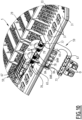
- connection 13 allows a rotation of each breeding enclosure 5 around a first axis of rotation R1 which is substantially horizontal, and a rotation of the first axis of rotation R1 relative to the chassis 3 around a second axis of rotation R2 which is substantially parallel to the first axis of rotation R1 ( figures 1 to 3 ).
- connection 13 advantageously comprises at least one connecting member 51 of the connecting rod type, pivotally mounted on the breeding enclosure 5 around the first axis of rotation R1 and pivotally mounted on the chassis 3 around the second axis of rotation R2.
- connection 13 typically comprises two connecting rod-type connecting members 51 for each breeding enclosure, each connecting member 51 connecting the breeding enclosure 5 to the chassis.
- the first axes of rotation R1 of the two connecting members of the same breeding enclosure are aligned with each other.
- the second axes of rotation R2 of the two connecting members 51 of the same enclosure 5 are aligned with each other.
- the breeding enclosure 5 has a proximal edge 55 and a distal edge 57 opposite each other, facing the two metal bars framing the breeding enclosure 5.
- proximal edge and the distal edge are longitudinal.
- edges 55, 57 are formed by segments of the flat collars 31 of the two half-enclosures pressed against each other.
- Link 13 connects proximal edge 55 to chassis 3.
- each connecting member 51 connects the proximal edge 55 to the metal bar 17 adjoining said proximal edge.
- connection 13 comprises, for each connection member 51, a sleeve 53 fixed to the metal bar 17 adjoining the proximal edge 55 of the breeding enclosure 5.
- the connection member 51 is pivotally mounted around the sleeve 53.
- the metal bar 17 thus constitutes the second axis of rotation R2.
- This sleeve 53 completely surrounds the metal bar 17.
- it is made up of two half-shells of generally semi-cylindrical shape, placed on either side of the metal bar 17.
- the two half-shells are rigidly fixed to each other. the other by any suitable means, for example by pins.
- the sleeve 53 is typically made of polyolefin. This reduces the wear of the connecting member 51, which is not in direct contact with the metal bar.
- each connecting member 51 advantageously comprises two half-clamps 59 independent of one another.
- the two half-clamps 59 together define two bearings 61, 63, substantially parallel to one another.
- the bearing 61 is intended to internally receive the sleeve 53.
- the bearing 63 is intended to internally receive a cylinder 65 formed on the proximal edge 55 of the breeding enclosure.
- Each half-clamp 59 therefore has the general shape of a W, with three blocks 67, 69 and 71 delimiting between them two hollows 73 and 75.
- the hollows 73 and 75 have semi-cylindrical shapes.
- the two half-clamps 59 are capable of being mounted on the breeding enclosure 5 in a stable open position, shown in the Figure 11 , in which the half-clamps 59 are connected to each other by a pivot connection 77.
- the axis of rotation of the pivot is substantially parallel to the first axis of rotation.
- the proximal edge 55 of the rack has, along the cylinder 65, two orifices 78. These orifices are offset towards the inside of the enclosure relative to the cylinder 65.
- the pivot connection 77 comprises two plates 79, parallel to each other, formed on the block 71 of one of the half-clamps ( figures 5 And 9 ).
- Each plate 79 carries pins 81 on its two opposite faces. The four pins 81 are aligned.
- the block 71 of the other half-clamp forms two pairs of flanges 83, each pair of flanges being designed to receive between its two flanges one of the plates 79.
- Cradles for receiving the trunnions 81 are hollowed out in the opposite faces of the two flanges of the same pair.
- the half-clamps 59 are first mounted on the enclosure 5 as illustrated in the Figure 10 .
- the plates 79 are each engaged in one of the orifices 78. They are engaged between the flanges 83 of the other half-clamp 59.
- the half-clamps form an angle of approximately 90° with each other. The rotation of the two half-clamps relative to each other in the direction of opening the clamp is blocked by reliefs formed on the half-clamps 59.
- the two half-clamps 59 are free to pivot relative to each other around the pivot connection 77 in the direction of closing.
- the cradles formed in the flanges 83 are provided so that the engagement of the pins 81 is easy, but that the extraction of the pins 81 from the cradles requires a significant effort, so as to prevent the two half-clamps from separating from each other involuntarily.
- each half-clamp 59 can pivot around the pivot connection 77 to the stable open position, shown in the Figure 11 .
- Each half-clamp 59 comprises an arm 84, carrying at its end a relief 84R.
- the relief 84R of each half-clamp is reversibly wedged in a housing 84M of the other half-clamp. This makes it possible to maintain the half-clamps 59 in the open position, without preventing the rotational movement of the half-clamps towards each other from being extended.
- the two half-clamps can be closed around the frame 3 by pivoting around the pivot connection 77 ( Figure 12 ).
- the arms 84 slide through the housings 84M.
- the hollows 75 are then placed around the cylinder 65, and the hollows 73 around the sleeve 53.
- the intermediate blocks 69 of the two half-clamps 59 are in abutment against each other, and the blocks 67 of the two half-clamps 59 are also in abutment against each other.
- the two half-clamps 59 are locked in this position by pins G shown in the Figure 13 , engaged in aligned orifices O of the two half-clamps 59. It is therefore understood that the assembly of the connecting member 51 is particularly simple. It allows easy installation of the breeding enclosures 5 on the chassis 3.
- the breeding enclosure 5 preferably comprises at least one stop zone 85 ( figure 14 ), cooperating with the connecting member 51 so as to limit the rotational movement of the breeding enclosure 5 relative to the connecting member 51 around the first axis of rotation R1.
- the breeding enclosure 5 comprises two stop zones 85, limiting the rotational movement of the breeding enclosure 5 relative to the connecting member 51 in the two opposite directions of rotation.
- zones 85 are reinforced by the fact that they comprise a greater number of ribs 34 than the other zones of the enclosure 5, so as to stiffen the structure of the breeding enclosure 5 at the level of said zones 85.
- these zones 85 are the zones of the peripheral wall 33 located opposite each connecting member.
- the zone 85 formed on the peripheral wall 33 of one of the half-racks limits rotation in one direction, and that formed on the wall 33 of the other half-rack limits rotation in the other direction.
- the breeding device 1 comprises a limiting device 86, limiting the movement of the breeding enclosure 5 relative to the chassis 3 in the vertical direction ( Figure 4 ).
- the limiting device 86 comprises at least one flexible link 87 which connects the chassis 3 to the breeding enclosure 5.
- the or each flexible link 87 is elastic. This makes it possible to cushion the movement of the breeding enclosure in the vertical direction.
- each breeding enclosure 5 is connected by two flexible links 87 to the frame 3.
- each flexible link 87 connects the distal edge 57 of the breeding enclosure 5 to the frame 3. More precisely, the link 87 connects the distal edge 57 to the metal bar 17 located opposite the connecting members 51.
- the breeding enclosure is connected on one side by the connecting members 51 to one of the metal bars 17, and on the other side by the flexible links 87 to the other metal bar 17.
- the distal edge 57 has orifices 89 allowing the passage of the flexible link 87.
- the ends of the flexible link 87 are fixed to the sleeve 53 on which the neighboring breeding enclosure 5 is hinged. As illustrated in the Figure 4 , the ends of the flexible link 87 are wound around the sleeve, in grooves 90 formed by the sleeve 53.
- the sleeves 53 may also include notches 88, visible on the Figure 12 , allowing the flexible link to be attached to the sleeve.
- orifices 89 are identical and positioned in the same way as the orifices 78.
- each half-rack is symmetrical with respect to a longitudinal median plane, perpendicular to the flat part 29.
- each breeding enclosure 5 is equipped with its own float 11, which thus constitutes the float device 10.
- the float 11 is linked to an area of the breeding enclosure 5 located near the distal edge 57.
- the float 11 is housed inside the breeding enclosure 5. It is fixed to the breeding enclosure 5 by any suitable means, for example by forming reliefs on the internal surface of the breeding enclosure, which hold the float 11 in place once the two half-enclosures 27 are engaged with each other.
- the float 11 is sized to float the enclosure containing the aquaculture animals until the end of breeding, that is to say when these animals have their maximum weight.
- the float device 10 can also be adapted as the breeding progresses, for example by adding buoyancy as the mass of the aquaculture animals in the enclosures increases.
- the device is designed to transmit wave motions to the breeding enclosures, and cause the aquaculture animals to roll over a significant distance on the inner surface of the enclosure and against each other, particularly during the ebb and flow of the tide.
- the device is shown when the water level is substantially at the level of the metal bars 17.
- the inner bottom 23 is substantially horizontal.
- the float device 10 is located at the water surface level.
- the two axes of rotation R1, R2 are substantially in a horizontal plane.
- the flexible ties 87 are not stretched.
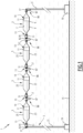
- the breeding enclosure 5 adopts an inclined position, the proximal edge 55 connected by the connection 13 to the frame 3 remaining higher and the distal edge 57 being lower.
- the connection 13 allows the breeding enclosure 5 to pivot around the two axes of rotation R1 and R2.
- the livestock 9 Due to the inclination, in particular due to the fact that the lower bottom 23 is inclined relative to the horizontal, the livestock 9 will roll on the inner bottom 23 and will roll against each other, accumulating towards the distal edge 57 of the breeding enclosure.
- the downward pivoting movement of the breeding enclosure 5 (arrow F1 of the Figure 3 ) is accompanied by a movement of general horizontal orientation of enclosure 5, materialized by arrow F2 of the Figure 3
- This general horizontal movement creates a shear force at the contact between the aquaculture animals and the breeding enclosure, which amplifies the movement of the breeding animals and allows them to slide down and to roll even at slight inclines. This shearing force, when repeated, can potentially free livestock that are stuck to the breeding enclosure.
- connection 13 makes it possible to transform the vertical movement of the water, due to the waves, into an agitation movement that is both vertical and horizontal which, associated with the inclination of the breeding enclosure 5, allows the aquaculture animals to slide down onto the flat mesh of the enclosure by rolling on this mesh against each other.
- the connecting members 51 at the end of their travel come into contact with the stop zones 85 of the breeding enclosure, which further reinforces the shearing effect. This promotes the detachment of the breeding animals, in particular oysters which could have stuck together by pearling between two periods of agitation.
- the limiting device 86 makes it possible to limit the vertical amplitude of the movement, which allows the breeder to adapt the system to the hydraulic conditions prevailing in the breeding area and to the seasonality of his breeding.
- breeding enclosure 5 is animated by movements opposite to those shown by the arrows F1 and F2 when the enclosure returns from its low position illustrated in the figure. Figure 3 to the intermediate position illustrated on the Figure 1 .
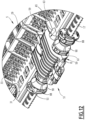
- the breeding enclosure 5 when the breeding enclosure 5 is located at the top of a wave, the breeding enclosure 5 adopts an inclination opposite to that illustrated in the Figure 3 .
- the distal edge 57 is higher than the metal bar 17, so that the aquaculture animals 9 roll down the lower bottom 23 towards the proximal edge 55.
- the breeding enclosure undergoes a pivoting movement relative to the metal bar 17, materialized by the arrow F3 of the Figure 2 . This pivoting is done upwards.
- the breeding enclosure 5 also undergoes a displacement in a general horizontal direction, materialized by the arrow F4 of the Figure 2 . Again, a shear force is created between the aquaculture animals and the breeding enclosure, which promotes the movement and rolling of the breeding animals 9 within the breeding enclosure 5.
- the connecting members 51 at the end of their travel come into contact with the stop zones 85 provided for this purpose on the breeding enclosure 5.
- the limiting device 86 limits the vertical travel upwards of the breeding enclosure 5 relative to the chassis 3.
- the breeding enclosure 5 is animated by movements opposite to those represented by the arrows F3 and F4 when it returns from its extreme high position materialized on the Figure 2 at the intermediate position shown on the Figure 1 .
- the breeding device 1 must be arranged on the foreshore, so that the breeding enclosures 5 are at the level of the water surface at least at one time during the tide.
- the choice of the level of installation of the breeding device on the foreshore allows the device to be adapted to the tidal conditions.
- the tidal range is characterized by two parameters: its amplitude, which varies from one day to the next (for example, in France, high tidal ranges alternate with low tidal ranges over a period of 15 days) and the speed of rise and fall of the water which, for example, follows the rule of twelfths, which means that at the beginning or end of the falling or rising tide, the speed of rise and fall is three times slower than at mid-tide.
- the limiting device 86 also makes it possible to adjust the amplitude and duration of agitation of the aquaculture animals, in order to regulate the desired effect on the animals being farmed.
- the breeding enclosures 5 are only agitated during a limited period of the tide. They are agitated between the moment when the crest of the waves reaches the lower position of the breeding enclosure (shown on the Figure 3 ), and the moment when the wave trough exceeds the high position of the breeding enclosures (represented on the Figure 2 ).
- the frame 3 comprises a plurality of metal bars 17, parallel to each other and regularly spaced from each other.
- the metal bars 17 are for example fixed to metal crosspieces 90.
- Each breeding enclosure is arranged between two metal bars 17. Its proximal edge 55 is connected by the connection 13 to one of the metal bars 17, and its distal edge 57 is connected by one or more flexible links 87 to the other metal bar 17.
- the neighboring breeding enclosure 5 is mounted in the same way. More precisely, the distal edge 55 of the neighboring breeding enclosure 5 is connected by the connection 13 to the metal bar 17 to which the first breeding enclosure is connected by the flexible connection(s) 87.
- each metal bar 17 is connected on one side by a connection 13 to a breeding enclosure 5, and on the other side by flexible connections 87 to another breeding enclosure.
- breeding enclosures 5 can be turned over very easily to combat fouling. Indeed, it is known that algae develop more easily on the sides of the breeding enclosures that are turned upwards, i.e. exposed to the sun. Furthermore, sea squirts develop on the side of the breeding enclosure that is in the shade, i.e. facing downwards.
- all the breeding enclosures 5 of the breeding device 1 are linked to the same float device 10.
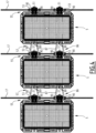
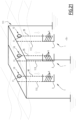
- the frame 3 comprises several metal bars 17 parallel to each other, spaced from each other at least vertically.
- the frame 3 comprises a parallelepiped structure.
- This structure comprises four vertical posts 91, these posts preferably being secured to each other by an upper frame 93 and by a lower frame 94.
- the metal bars 17 are rigidly fixed by their opposite end to two of the posts 91, and are superimposed in the vertical direction. The metal bars 17 are thus arranged on a large face of the parallelepiped.
- a breeding enclosure 5 is connected to each metal bar 17, the breeding enclosures 5 being superimposed on top of each other.
- the metal bars 17 are regularly spaced from each other in the vertical direction.
- the breeding enclosures 5 are placed inside the frame, and swing between the posts 91.
- the float device 10 comprises a single float 11.
- the float device 10 is connected by a flexible connection 95 to the upper breeding enclosure 5, located highest in the stack of breeding enclosures.
- the flexible connection 95 is of any suitable type.
- the flexible connection 95 comprises, for example, one or more cables, each connecting the float to the enclosure. Alternatively, it comprises ropes, cords, chains, or any other type of flexible connection.
- Intermediate connections 97 typically cables or ropes, connect each breeding enclosure 5 to the breeding enclosure located immediately above and/or to the breeding enclosure located immediately below in the stack.
- these intermediate connections are rigid spacers, which pivot for example around the axes located on the distal edge of the breeding enclosures.
- a rigid connection can be a factor of cohesion of the movement promoting equal agitation of all the breeding enclosures.
- a flexible connection could, in the event of high-frequency agitation (chopping), promote, following the inertia of all the breeding enclosures, the agitation of the upper breeding enclosures with the consequence of excessive agitation of the breeding animals in the upper enclosures versus insufficient agitation of the breeding animals in the lower enclosures.
- the flexible connection 95 connects the float device 10 to the distal edge 57 of the upper breeding enclosure.
- the intermediate connection(s) 97 connect the distal edges of the different breeding enclosures to each other.
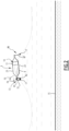
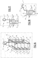
- the breeding device according to the second embodiment of the invention is designed to be able to be used in deep water, that is to say in an area where the breeding enclosures 5 are not uncovered at low tide.
- the chassis 3 rests on the bottom 15. It is for example mounted on a pile driven into the bottom 15.
- the length of the flexible connection 95 is chosen such that the float device 10, when the flexible connection 95 is stretched, is in the tidal zone, that is to say at a level between the water level at low tide (MB on the figure 19 ) and the water level at high tide (MH on the figure 19 ).
- the length of the flexible connection is chosen so that, at least at one point during the tidal cycle, the float device 10 floats on the surface of the water with the flexible connection 95 taut, such that water displacements due to waves are transmitted by the float device 10 and the flexible connection 95 to the upper rearing enclosure.
- the intermediate links 97 are chosen to have lengths such that, when the upper enclosure 5 pivots upwards, it drives the enclosure located immediately below it, which itself drives the enclosure immediately below it, etc.
- the length of the intermediate links 97 is chosen to be equal to the vertical spacing between the metal bars 17.
- the float 11 is connected to the upper breeding enclosure by two cables.
- Each breeding enclosure is connected to the enclosure immediately above and/or the enclosure immediately below by two intermediate links 97.
- the limiting device 86 comprises at least one flexible link 99, connecting the upper breeding enclosure to the chassis and limiting the downward travel of said enclosure.
- the limiting device 86 comprises two flexible links 99, connecting the upper enclosure to the chassis.
- the limiting device 86 comprises at least one flexible link 101, connecting the lower enclosure 5, located at the bottom of the stack of enclosures, to the chassis and limiting the upward travel of the lower enclosure.
- the limiting device 86 comprises two flexible links 101 connecting the lower enclosure to the chassis 3.
- flexible links 101 could not be mounted on the lower enclosure 101 but be mounted on any other enclosure in the stack.
- the float device 10 When the tide is high, as shown in the Figure 17 , the float device 10 is completely submerged, and is located at a distance below the water level.
- the flexible connection 95 is taut.
- the breeding enclosures 5 occupy their uppermost positions. This position is defined by the limiting device 86.
- this position is defined by the length of the flexible link(s) 101, which are also taut.
- the float device 10 urges the upper breeding enclosure 5 upwards, this urge being transmitted by each breeding enclosure 5 to the immediately lower breeding enclosure through the intermediate links 97.
- This vertical upward movement is limited, if necessary, by the limiting device 86.
- the upward movement is limited by the flexible links 101.
- the float device 10 When the water level drops, the float device 10 is pulled downwards. This gives slack to the flexible connection 95, and the enclosures 5 are pulled downwards under the effect of their own weight.
- the downward movement of the upper enclosure 5 is limited, if necessary, by the limiting device 86. In the embodiment described above, the downward movement is limited by the flexible connection(s) 99.
- the downward movement of each breeding enclosure 5 relative to the upper enclosure is limited by the length of the intermediate connections 97.
- the level of installation of the float device 10 in relation to the height of the tidal range that is to say the height of the water at high tide and the height of the water at low tide, makes it possible to choose the operating conditions of the system.
- the choice of the length of the flexible connection 95 makes it possible to adapt the device to the tidal conditions.
- the tidal range is characterized by two parameters: its amplitude, which varies from one day to the next (for example, in France, high tidal ranges alternate with low tidal ranges over a period of 15 days) and the speed of rise and fall of the water which, for example, follows the rule of twelfths, which means that at the beginning or end of the falling or rising tide, the speed of rise and fall is three times slower than at mid-tide.
- the amplitude of the movements, and the duration of the periods of agitation can also be adjusted by the limiting device 86. In the exemplary embodiment described above, this adjustment is made by choosing the length of the flexible links 99 and 101.
- the second embodiment of the invention can also be applied with breeding devices placed on the foreshore, when it is desired to set in motion a superposition of enclosures and/or work with the same tide level over the entire surface of the foreshore. This allows the breeder to make zootechnical choices: frequency of agitation, amplitude of movement, duration of agitation.
- the flexible connections 95 of the different devices are of variable lengths, as illustrated in the figure 19 These lengths are chosen so that the respective flexible connections of the different devices are stretched for approximately the same water level.
- the float device 10 is not housed inside the breeding enclosure. On the contrary, the float device 10 is placed outside the breeding enclosure and is connected by a flexible connection 95 to the breeding enclosure 5.
- the length of the flexible connection 95 is chosen such that the float device 10, when the flexible connection 95 is stretched, is in the tidal zone
- the breeding enclosures 5 can thus be placed outside the foreshore, in deep water.
- each breeding enclosure is alternatively equipped with its own float 103, in addition to the float device 10.
- the floats 103 are for example arranged in the enclosures 5. They are sized to compensate at least partially for the mass of aquaculture animals at the end of breeding. This makes it possible to limit the buoyancy of the float device 10 necessary for the movement, and therefore the forces transmitted by the float device 10 installed in the tidal range in the event of a storm for example.
- This aspect is very important because the cumulative effect of the floats according to their number, their arrangement and their volume, leaves the farmer the possibility of definitively determining the ideal assembly perfectly adapted to his deep water site, knowing that the hydrodynamic conditions are invariable, while taking into account storm risks, and therefore allowing him to obtain in a constant and regular manner the quality of product that he has chosen.
- the float device 10 comprises not a single float but a garland 105 of floats. Such an arrangement is illustrated in the figure 20
- This garland 105 comprises a plurality of floats 107, mounted one behind the other along a flexible link 109, a lower end of which is secured to the flexible link 95.
- the volume, and therefore the buoyancy, of the floats 107 increases from the upper end to the lower end of the flexible link 109.
- This variant can be combined with the previous one (float 103 specific to each enclosure in addition to the float device 10).
- connection 13 is not mounted on the proximal edge of each breeding enclosure 5. If we consider the median plane of the breeding enclosure 5, perpendicular to the lower bottom and parallel to the axes of rotation R1 and R2, the connection 13 can connect any point located on one side of this median plane to the chassis 3. The float 11 is preferably connected to any point located on the other side of the median plane.
- the flexible links can be linked to any point of the enclosure located on the side of the median plane opposite the connection 13.
- the invention has been described for a device in which the breeding enclosures 5 are connected to the frame by connecting rod-type connecting members, creating a shearing force between the aquaculture animals and the enclosure under the effect of the vertical displacement of the enclosures.
- the invention is also applicable to breeding enclosures connected to the frame by simple pivoting connections around a single axis of rotation, as described in FR2576484 , or to systems of rotating trays on which the breeding enclosures are placed, or to systems of cages containing numerous enclosures, said cages being able to pivot around an axis so as to ensure movement of the enclosures similar to that described above.
- the chassis 3 does not rest directly on the seabed 15.
- the chassis 3 is located slightly above the seabed 15. It is mounted, for example, on a supporting structure 111, which rests fixedly on the seabed 15.
- the 111 supporting structure is suitable for any type: table, gantry, etc.
- the supporting structure 111 carries one or more breeding devices 1.
- Each chassis 3 is mounted on the supporting structure 111 by any suitable means: rigid metal bars 113, direct welds, flexible metal cables, etc.
- the limiting device 86 comprises fixed stops in addition to the flexible links 87, 99, 101.
- the stops are advantageously metal bars rigidly fixed to the frame, above and below the stack of breeding enclosures.
- Such an arrangement is particularly well suited when the breeding enclosures are placed on rotating platforms linked to the chassis.
- aspects 2. and 4. are claimed jointly and allow excellent results to be achieved for adapting the system to the breeding conditions. Implementing aspects 1. and/or 3., in addition to aspects 2. and 4., further improves the results.
Landscapes
- Life Sciences & Earth Sciences (AREA)
- Environmental Sciences (AREA)
- Marine Sciences & Fisheries (AREA)
- Zoology (AREA)
- Animal Husbandry (AREA)
- Biodiversity & Conservation Biology (AREA)
- Farming Of Fish And Shellfish (AREA)
- Catching Or Destruction (AREA)
Claims (9)
- Aufzuchtvorrichtung von Aquakulturtieren im Meer, wobei die Aquakulturtiere Muscheln sind, die Vorrichtung (1) umfassend:- einen Rahmen (3);- mindestens eine Aufzuchtkammer (5), die innen ein Aufnahmevolumen (7) für die Aquakulturtiere (9) begrenzt;- eine Schwimmervorrichtung (10), die mit der mindestens einen Aufzuchtkammer (5) verbunden ist;- eine Verbindung (13) der mindestens einen Aufzuchtkammer (5) mit dem Rahmen (3), die eine Drehung des mindestens einen Aufzuchtkammer (5) in Bezug auf den Rahmen (3) um mindestens eine im Wesentlichen horizontale Drehachse zulässt;- eine Begrenzungsvorrichtung (86), die die Auslenkung der mindestens einen Aufzuchtkammer (5) in Bezug auf den Rahmen (3) in vertikaler Richtung begrenzt; wobei jeder Aufzuchtbehälter (5) einen im Wesentlichen flachen unteren Boden (23) aufweist;die Schwimmervorrichtung (10) dem Meeresspiegel folgt, wenn die Flut auf der Höhe der Schwimmervorrichtung (10) ist, und eine Neigungsänderung von oben nach unten und von unten nach oben auf die Aufzuchtkammer (5) überträgt, wenn das Meer steigt und fällt, sodass die Muscheln auf den unteren Boden (23) hinunterrutschen;wobei die Begrenzungsvorrichtung (86) es ermöglicht, die vertikale Amplitude der Aufwärtsbewegung und der Abwärtsbewegung aufgrund der Schwimmervorrichtung (10) zu begrenzen, wobei die Aufzuchtvorrichtung dadurch gekennzeichnet ist, dass die Begrenzungsvorrichtung (86) mindestens eine flexible Verbindung (87, 99, 101) umfasst, die den Rahmen (3) mit der mindestens einen Aufzuchtkammer (5) verbindet, wobei die mindestens eine flexible Verbindung (87, 99, 101) elastisch ist,die mindestens eine Aufzuchtkammer (5) einen proximalen Rand (55) und einen distalen Rand (57) aufweist, die einander gegenüber sind, wobei die Verbindung (13) den proximalen Rand (55) mit dem Rahmen (3) verbindet, wobei das mindestens eine flexible Verbindung (87, 99, 101) den distalen Rand (57) mit dem Rahmen (3) verbindet.
- Vorrichtung nach Anspruch 1, wobei die Schwimmervorrichtung (10) mit einem Bereich der mindestens einen Aufzuchtkammer (5) verbunden ist, der sich in der Nähe des distalen Rands (57) befindet.
- Vorrichtung nach Anspruch 1 oder 2, wobei der Rahmen (3) eine Vielzahl von Metallstangen (17) umfasst, die parallel zueinander und zumindest horizontal voneinander beabstandet sind, die Aufzuchtvorrichtung (1) umfassend eine Vielzahl von Aufzuchtkammern (5), die jeweils zwischen zwei der Metallstangen (17) angeordnet sind, wobei der proximale Rand (55) der Aufzuchtkammer (5) durch die Verbindung (13) mit einer der zwei Metallstangen (17) verbunden ist, wobei der distale Rand (57) der Aufzuchtkammer (5) durch die flexible Verbindung (87) mit der anderen der zwei Metallstangen (17) verbunden ist.
- Vorrichtung nach einem der Ansprüche 1 bis 3, wobei der Rahmen (3) mehrere Metallstangen (17) umfasst, die parallel zueinander und zumindest vertikal voneinander beabstandet sind, die Aufzuchtvorrichtung (1) umfassend mehrere Aufzuchtkammern (5), die übereinander angeordnet sind, wobei jede mit einer der Metallstangen (17) verbunden ist, wobei alle Aufzuchtkammern (5) mit ein und derselben Schwimmervorrichtung (10) verbunden sind.
- Vorrichtung nach Anspruch 4, wobei eine erste flexible Verbindung (99) die obere Aufzuchtkammer (5) mit dem Rahmen (3) verbindet, wodurch die Auslenkung der Aufzuchtkammern (5) nach unten begrenzt ist.
- Vorrichtung nach Anspruch 4 oder 5, wobei eine zweite flexible Verbindung (101) eine der Aufzuchtkammern (5) mit dem Rahmen (3) verbindet, wodurch die Auslenkung der Aufzuchtkammern (5) nach oben begrenzt ist.
- Vorrichtung nach einem der vorherigen Ansprüche, wobei die Verbindung (13) eine Drehung der mindestens einen Aufzuchtkammer (5) um eine im Wesentlichen horizontale erste Drehachse (R1) und eine Drehung der ersten Drehachse (R1) in Bezug auf den Rahmen (3) um eine zweite Drehachse (R2) im Wesentlichen parallel zu der ersten Drehachse (R1) zulässt.
- Vorrichtung nach Anspruch 7, wobei die Verbindung (13) mindestens ein Verbindungselement (51) vom Typ Pleuelstange umfasst, das schwenkbar um die erste Drehachse (R1) an der mindestens einen Aufzuchtkammer (5) montiert ist und schwenkbar um die zweite Drehachse (R2) an dem Rahmen (3) montiert ist.
- Vorrichtung nach einem der Ansprüche 7 oder 8, wobei der im Wesentlichen flache untere Boden (23) parallel zu der ersten und der zweiten Drehachse (R1, R2) ist.
Applications Claiming Priority (2)
| Application Number | Priority Date | Filing Date | Title |
|---|---|---|---|
| FR1760136A FR3054954B1 (fr) | 2017-10-27 | 2017-10-27 | Dispositif d'elevage en mer d'animaux d'aquaculture |
| PCT/EP2018/079454 WO2019081733A1 (fr) | 2017-10-27 | 2018-10-26 | Dispositif d'élevage en mer d'animaux d'aquaculture |
Publications (3)
| Publication Number | Publication Date |
|---|---|
| EP3700331A1 EP3700331A1 (de) | 2020-09-02 |
| EP3700331C0 EP3700331C0 (de) | 2025-03-12 |
| EP3700331B1 true EP3700331B1 (de) | 2025-03-12 |
Family
ID=60450928
Family Applications (1)
| Application Number | Title | Priority Date | Filing Date |
|---|---|---|---|
| EP18789452.2A Active EP3700331B1 (de) | 2017-10-27 | 2018-10-26 | Vorrichtung zur aufzucht von aquakulturtieren auf dem meer |
Country Status (8)
| Country | Link |
|---|---|
| US (1) | US20200281171A1 (de) |
| EP (1) | EP3700331B1 (de) |
| JP (1) | JP2021500062A (de) |
| KR (1) | KR20200098489A (de) |
| CN (1) | CN111278278A (de) |
| AU (1) | AU2018356645A1 (de) |
| FR (1) | FR3054954B1 (de) |
| WO (1) | WO2019081733A1 (de) |
Families Citing this family (1)
| Publication number | Priority date | Publication date | Assignee | Title |
|---|---|---|---|---|
| CN114176033B (zh) * | 2021-12-07 | 2022-10-21 | 中国海洋大学 | 双壳贝类肌肉组织非致死性采样装置及方法 |
Family Cites Families (8)
| Publication number | Priority date | Publication date | Assignee | Title |
|---|---|---|---|---|
| NZ214914A (en) * | 1985-01-30 | 1987-06-30 | Wayne Robert Moxham | Rotatable water-permeable container for cultivating molluscs |
| US4704990A (en) * | 1985-01-30 | 1987-11-10 | Moxham Wayne R | Cultivating molluscs |
| FR2908013A1 (fr) * | 2006-11-07 | 2008-05-09 | Seaside Park Sarl | Casier, notamment pour table ostreicole et ensemble forme d'une table ostreicole et d'au moins un casier du type precite |
| US9439402B2 (en) * | 2008-08-27 | 2016-09-13 | Ecosea Farming S.A. | Aquaculture net and flotation structure |
| FR3003128B1 (fr) * | 2013-03-18 | 2016-03-11 | Patrick Drevici | Portique pour l'elevage d'huitres |
| CN104904634B (zh) * | 2015-06-02 | 2018-07-31 | 山东省海洋资源与环境研究院 | 一种牡蛎单体的养成装置 |
| CN106359213A (zh) * | 2016-12-01 | 2017-02-01 | 烟台市水产研究所 | 一种海洋牧场扇贝亲体饲育装置及其构建方法 |
| FR3066678B1 (fr) * | 2017-05-24 | 2019-06-07 | Seadelicious | Dispositif et procede d'elevage d'huitres |
-
2017
- 2017-10-27 FR FR1760136A patent/FR3054954B1/fr active Active
-
2018
- 2018-10-26 US US16/759,321 patent/US20200281171A1/en not_active Abandoned
- 2018-10-26 EP EP18789452.2A patent/EP3700331B1/de active Active
- 2018-10-26 JP JP2020524112A patent/JP2021500062A/ja active Pending
- 2018-10-26 CN CN201880069879.1A patent/CN111278278A/zh active Pending
- 2018-10-26 WO PCT/EP2018/079454 patent/WO2019081733A1/fr not_active Ceased
- 2018-10-26 KR KR1020207012198A patent/KR20200098489A/ko not_active Withdrawn
- 2018-10-26 AU AU2018356645A patent/AU2018356645A1/en not_active Abandoned
Also Published As
| Publication number | Publication date |
|---|---|
| FR3054954A1 (fr) | 2018-02-16 |
| KR20200098489A (ko) | 2020-08-20 |
| EP3700331C0 (de) | 2025-03-12 |
| JP2021500062A (ja) | 2021-01-07 |
| EP3700331A1 (de) | 2020-09-02 |
| CN111278278A (zh) | 2020-06-12 |
| US20200281171A1 (en) | 2020-09-10 |
| FR3054954B1 (fr) | 2019-04-05 |
| AU2018356645A1 (en) | 2020-05-07 |
| WO2019081733A1 (fr) | 2019-05-02 |
Similar Documents
| Publication | Publication Date | Title |
|---|---|---|
| EP3700332B1 (de) | Vorrichtung zur aufzucht von aquakulturtieren auf dem meer | |
| EP3490372B1 (de) | Vorrichtung zur aufzucht von aquakulturtieren auf dem meer | |
| EP3700329B1 (de) | Vorrichtung zur aufzucht von krustentieren auf dem meer | |
| EP3700331B1 (de) | Vorrichtung zur aufzucht von aquakulturtieren auf dem meer | |
| EP3629716B1 (de) | Vorrichtung und verfahren für molluskenfarm | |
| WO2019081740A1 (fr) | Dispositif d'élevage en mer d'animaux d'aquaculture | |
| EP3993620B1 (de) | Gehäuse, säule und verfahren zur züchtung von muscheln | |
| EP4512242A1 (de) | Vorrichtung zur schalentierzucht und verfahren dafür |
Legal Events
| Date | Code | Title | Description |
|---|---|---|---|
| STAA | Information on the status of an ep patent application or granted ep patent |
Free format text: STATUS: UNKNOWN |
|
| STAA | Information on the status of an ep patent application or granted ep patent |
Free format text: STATUS: THE INTERNATIONAL PUBLICATION HAS BEEN MADE |
|
| PUAI | Public reference made under article 153(3) epc to a published international application that has entered the european phase |
Free format text: ORIGINAL CODE: 0009012 |
|
| STAA | Information on the status of an ep patent application or granted ep patent |
Free format text: STATUS: REQUEST FOR EXAMINATION WAS MADE |
|
| 17P | Request for examination filed |
Effective date: 20200424 |
|
| AK | Designated contracting states |
Kind code of ref document: A1 Designated state(s): AL AT BE BG CH CY CZ DE DK EE ES FI FR GB GR HR HU IE IS IT LI LT LU LV MC MK MT NL NO PL PT RO RS SE SI SK SM TR |
|
| AX | Request for extension of the european patent |
Extension state: BA ME |
|
| DAV | Request for validation of the european patent (deleted) | ||
| DAX | Request for extension of the european patent (deleted) | ||
| STAA | Information on the status of an ep patent application or granted ep patent |
Free format text: STATUS: EXAMINATION IS IN PROGRESS |
|
| 17Q | First examination report despatched |
Effective date: 20231019 |
|
| GRAP | Despatch of communication of intention to grant a patent |
Free format text: ORIGINAL CODE: EPIDOSNIGR1 |
|
| STAA | Information on the status of an ep patent application or granted ep patent |
Free format text: STATUS: GRANT OF PATENT IS INTENDED |
|
| INTG | Intention to grant announced |
Effective date: 20240722 |
|
| GRAJ | Information related to disapproval of communication of intention to grant by the applicant or resumption of examination proceedings by the epo deleted |
Free format text: ORIGINAL CODE: EPIDOSDIGR1 |
|
| STAA | Information on the status of an ep patent application or granted ep patent |
Free format text: STATUS: EXAMINATION IS IN PROGRESS |
|
| INTC | Intention to grant announced (deleted) | ||
| GRAP | Despatch of communication of intention to grant a patent |
Free format text: ORIGINAL CODE: EPIDOSNIGR1 |
|
| STAA | Information on the status of an ep patent application or granted ep patent |
Free format text: STATUS: GRANT OF PATENT IS INTENDED |
|
| INTG | Intention to grant announced |
Effective date: 20241122 |
|
| GRAS | Grant fee paid |
Free format text: ORIGINAL CODE: EPIDOSNIGR3 |
|
| GRAA | (expected) grant |
Free format text: ORIGINAL CODE: 0009210 |
|
| STAA | Information on the status of an ep patent application or granted ep patent |
Free format text: STATUS: THE PATENT HAS BEEN GRANTED |
|
| AK | Designated contracting states |
Kind code of ref document: B1 Designated state(s): AL AT BE BG CH CY CZ DE DK EE ES FI FR GB GR HR HU IE IS IT LI LT LU LV MC MK MT NL NO PL PT RO RS SE SI SK SM TR |
|
| REG | Reference to a national code |
Ref country code: GB Ref legal event code: FG4D Free format text: NOT ENGLISH |
|
| REG | Reference to a national code |
Ref country code: CH Ref legal event code: EP |
|
| REG | Reference to a national code |
Ref country code: DE Ref legal event code: R096 Ref document number: 602018080060 Country of ref document: DE |
|
| REG | Reference to a national code |
Ref country code: IE Ref legal event code: FG4D Free format text: LANGUAGE OF EP DOCUMENT: FRENCH |
|
| U01 | Request for unitary effect filed |
Effective date: 20250319 |
|
| U07 | Unitary effect registered |
Designated state(s): AT BE BG DE DK EE FI FR IT LT LU LV MT NL PT RO SE SI Effective date: 20250325 |
|
| PG25 | Lapsed in a contracting state [announced via postgrant information from national office to epo] |
Ref country code: RS Free format text: LAPSE BECAUSE OF FAILURE TO SUBMIT A TRANSLATION OF THE DESCRIPTION OR TO PAY THE FEE WITHIN THE PRESCRIBED TIME-LIMIT Effective date: 20250612 |
|
| PG25 | Lapsed in a contracting state [announced via postgrant information from national office to epo] |
Ref country code: ES Free format text: LAPSE BECAUSE OF FAILURE TO SUBMIT A TRANSLATION OF THE DESCRIPTION OR TO PAY THE FEE WITHIN THE PRESCRIBED TIME-LIMIT Effective date: 20250312 |
|
| PG25 | Lapsed in a contracting state [announced via postgrant information from national office to epo] |
Ref country code: NO Free format text: LAPSE BECAUSE OF FAILURE TO SUBMIT A TRANSLATION OF THE DESCRIPTION OR TO PAY THE FEE WITHIN THE PRESCRIBED TIME-LIMIT Effective date: 20250612 |
|
| PG25 | Lapsed in a contracting state [announced via postgrant information from national office to epo] |
Ref country code: HR Free format text: LAPSE BECAUSE OF FAILURE TO SUBMIT A TRANSLATION OF THE DESCRIPTION OR TO PAY THE FEE WITHIN THE PRESCRIBED TIME-LIMIT Effective date: 20250312 |
|
| PG25 | Lapsed in a contracting state [announced via postgrant information from national office to epo] |
Ref country code: GR Free format text: LAPSE BECAUSE OF FAILURE TO SUBMIT A TRANSLATION OF THE DESCRIPTION OR TO PAY THE FEE WITHIN THE PRESCRIBED TIME-LIMIT Effective date: 20250613 |
|
| PG25 | Lapsed in a contracting state [announced via postgrant information from national office to epo] |
Ref country code: SM Free format text: LAPSE BECAUSE OF FAILURE TO SUBMIT A TRANSLATION OF THE DESCRIPTION OR TO PAY THE FEE WITHIN THE PRESCRIBED TIME-LIMIT Effective date: 20250312 |
|
| PG25 | Lapsed in a contracting state [announced via postgrant information from national office to epo] |
Ref country code: PL Free format text: LAPSE BECAUSE OF FAILURE TO SUBMIT A TRANSLATION OF THE DESCRIPTION OR TO PAY THE FEE WITHIN THE PRESCRIBED TIME-LIMIT Effective date: 20250312 |
|
| PG25 | Lapsed in a contracting state [announced via postgrant information from national office to epo] |
Ref country code: CZ Free format text: LAPSE BECAUSE OF FAILURE TO SUBMIT A TRANSLATION OF THE DESCRIPTION OR TO PAY THE FEE WITHIN THE PRESCRIBED TIME-LIMIT Effective date: 20250312 |
|
| PGFP | Annual fee paid to national office [announced via postgrant information from national office to epo] |
Ref country code: IE Payment date: 20250918 Year of fee payment: 8 |
|
| PG25 | Lapsed in a contracting state [announced via postgrant information from national office to epo] |
Ref country code: SK Free format text: LAPSE BECAUSE OF FAILURE TO SUBMIT A TRANSLATION OF THE DESCRIPTION OR TO PAY THE FEE WITHIN THE PRESCRIBED TIME-LIMIT Effective date: 20250312 |
|
| PG25 | Lapsed in a contracting state [announced via postgrant information from national office to epo] |
Ref country code: IS Free format text: LAPSE BECAUSE OF FAILURE TO SUBMIT A TRANSLATION OF THE DESCRIPTION OR TO PAY THE FEE WITHIN THE PRESCRIBED TIME-LIMIT Effective date: 20250712 |
|
| U20 | Renewal fee for the european patent with unitary effect paid |
Year of fee payment: 8 Effective date: 20251029 |
|
| PGFP | Annual fee paid to national office [announced via postgrant information from national office to epo] |
Ref country code: GB Payment date: 20251023 Year of fee payment: 8 |
|
| PLBE | No opposition filed within time limit |
Free format text: ORIGINAL CODE: 0009261 |
|
| STAA | Information on the status of an ep patent application or granted ep patent |
Free format text: STATUS: NO OPPOSITION FILED WITHIN TIME LIMIT |
|
| REG | Reference to a national code |
Ref country code: CH Ref legal event code: L10 Free format text: ST27 STATUS EVENT CODE: U-0-0-L10-L00 (AS PROVIDED BY THE NATIONAL OFFICE) Effective date: 20260121 |
|
| 26N | No opposition filed |
Effective date: 20251215 |