EP4414733A2 - Vorrichtung zur erzeugung eines hochfrequenten magnetfeldes - Google Patents
Vorrichtung zur erzeugung eines hochfrequenten magnetfeldes Download PDFInfo
- Publication number
- EP4414733A2 EP4414733A2 EP24185109.6A EP24185109A EP4414733A2 EP 4414733 A2 EP4414733 A2 EP 4414733A2 EP 24185109 A EP24185109 A EP 24185109A EP 4414733 A2 EP4414733 A2 EP 4414733A2
- Authority
- EP
- European Patent Office
- Prior art keywords
- coils
- magnetic field
- generating device
- field generating
- frequency magnetic
- Prior art date
- Legal status (The legal status is an assumption and is not a legal conclusion. Google has not performed a legal analysis and makes no representation as to the accuracy of the status listed.)
- Granted
Links
Images









Classifications
-
- G—PHYSICS
- G01—MEASURING; TESTING
- G01R—MEASURING ELECTRIC VARIABLES; MEASURING MAGNETIC VARIABLES
- G01R33/00—Arrangements or instruments for measuring magnetic variables
- G01R33/20—Arrangements or instruments for measuring magnetic variables involving magnetic resonance
- G01R33/60—Arrangements or instruments for measuring magnetic variables involving magnetic resonance using electron paramagnetic resonance
-
- G—PHYSICS
- G01—MEASURING; TESTING
- G01R—MEASURING ELECTRIC VARIABLES; MEASURING MAGNETIC VARIABLES
- G01R33/00—Arrangements or instruments for measuring magnetic variables
- G01R33/20—Arrangements or instruments for measuring magnetic variables involving magnetic resonance
- G01R33/28—Details of apparatus provided for in groups G01R33/44 - G01R33/64
- G01R33/38—Systems for generation, homogenisation or stabilisation of the main or gradient magnetic field
-
- G—PHYSICS
- G01—MEASURING; TESTING
- G01N—INVESTIGATING OR ANALYSING MATERIALS BY DETERMINING THEIR CHEMICAL OR PHYSICAL PROPERTIES
- G01N24/00—Investigating or analyzing materials by the use of nuclear magnetic resonance, electron paramagnetic resonance or other spin effects
- G01N24/10—Investigating or analyzing materials by the use of nuclear magnetic resonance, electron paramagnetic resonance or other spin effects by using electron paramagnetic resonance
-
- G—PHYSICS
- G01—MEASURING; TESTING
- G01R—MEASURING ELECTRIC VARIABLES; MEASURING MAGNETIC VARIABLES
- G01R33/00—Arrangements or instruments for measuring magnetic variables
- G01R33/02—Measuring direction or magnitude of magnetic fields or magnetic flux
- G01R33/032—Measuring direction or magnitude of magnetic fields or magnetic flux using magneto-optic devices, e.g. Faraday or Cotton-Mouton effect
-
- G—PHYSICS
- G01—MEASURING; TESTING
- G01R—MEASURING ELECTRIC VARIABLES; MEASURING MAGNETIC VARIABLES
- G01R33/00—Arrangements or instruments for measuring magnetic variables
- G01R33/12—Measuring magnetic properties of articles or specimens of solids or fluids
- G01R33/1284—Spin resolved measurements; Influencing spins during measurements, e.g. in spintronics devices
-
- G—PHYSICS
- G01—MEASURING; TESTING
- G01R—MEASURING ELECTRIC VARIABLES; MEASURING MAGNETIC VARIABLES
- G01R33/00—Arrangements or instruments for measuring magnetic variables
- G01R33/20—Arrangements or instruments for measuring magnetic variables involving magnetic resonance
- G01R33/28—Details of apparatus provided for in groups G01R33/44 - G01R33/64
- G01R33/32—Excitation or detection systems, e.g. using radio frequency signals
- G01R33/323—Detection of MR without the use of RF or microwaves, e.g. force-detected MR, thermally detected MR, MR detection via electrical conductivity, optically detected MR
-
- G—PHYSICS
- G01—MEASURING; TESTING
- G01R—MEASURING ELECTRIC VARIABLES; MEASURING MAGNETIC VARIABLES
- G01R33/00—Arrangements or instruments for measuring magnetic variables
- G01R33/20—Arrangements or instruments for measuring magnetic variables involving magnetic resonance
- G01R33/28—Details of apparatus provided for in groups G01R33/44 - G01R33/64
- G01R33/32—Excitation or detection systems, e.g. using radio frequency signals
- G01R33/34—Constructional details, e.g. resonators, specially adapted to MR
-
- G—PHYSICS
- G01—MEASURING; TESTING
- G01R—MEASURING ELECTRIC VARIABLES; MEASURING MAGNETIC VARIABLES
- G01R33/00—Arrangements or instruments for measuring magnetic variables
- G01R33/20—Arrangements or instruments for measuring magnetic variables involving magnetic resonance
- G01R33/28—Details of apparatus provided for in groups G01R33/44 - G01R33/64
- G01R33/32—Excitation or detection systems, e.g. using radio frequency signals
- G01R33/34—Constructional details, e.g. resonators, specially adapted to MR
- G01R33/34007—Manufacture of RF coils, e.g. using printed circuit board technology; additional hardware for providing mechanical support to the RF coil assembly or to part thereof, e.g. a support for moving the coil assembly relative to the remainder of the MR system
-
- G—PHYSICS
- G01—MEASURING; TESTING
- G01R—MEASURING ELECTRIC VARIABLES; MEASURING MAGNETIC VARIABLES
- G01R33/00—Arrangements or instruments for measuring magnetic variables
- G01R33/20—Arrangements or instruments for measuring magnetic variables involving magnetic resonance
- G01R33/28—Details of apparatus provided for in groups G01R33/44 - G01R33/64
- G01R33/32—Excitation or detection systems, e.g. using radio frequency signals
- G01R33/34—Constructional details, e.g. resonators, specially adapted to MR
- G01R33/34046—Volume type coils, e.g. bird-cage coils; Quadrature bird-cage coils; Circularly polarised coils
- G01R33/34061—Helmholtz coils
-
- G—PHYSICS
- G01—MEASURING; TESTING
- G01R—MEASURING ELECTRIC VARIABLES; MEASURING MAGNETIC VARIABLES
- G01R33/00—Arrangements or instruments for measuring magnetic variables
- G01R33/20—Arrangements or instruments for measuring magnetic variables involving magnetic resonance
- G01R33/28—Details of apparatus provided for in groups G01R33/44 - G01R33/64
- G01R33/32—Excitation or detection systems, e.g. using radio frequency signals
- G01R33/36—Electrical details, e.g. matching or coupling of the coil to the receiver
-
- G—PHYSICS
- G01—MEASURING; TESTING
- G01R—MEASURING ELECTRIC VARIABLES; MEASURING MAGNETIC VARIABLES
- G01R33/00—Arrangements or instruments for measuring magnetic variables
- G01R33/20—Arrangements or instruments for measuring magnetic variables involving magnetic resonance
- G01R33/28—Details of apparatus provided for in groups G01R33/44 - G01R33/64
- G01R33/38—Systems for generation, homogenisation or stabilisation of the main or gradient magnetic field
- G01R33/385—Systems for generation, homogenisation or stabilisation of the main or gradient magnetic field using gradient magnetic field coils
-
- H—ELECTRICITY
- H01—ELECTRIC ELEMENTS
- H01F—MAGNETS; INDUCTANCES; TRANSFORMERS; SELECTION OF MATERIALS FOR THEIR MAGNETIC PROPERTIES
- H01F5/00—Coils
-
- H—ELECTRICITY
- H01—ELECTRIC ELEMENTS
- H01F—MAGNETS; INDUCTANCES; TRANSFORMERS; SELECTION OF MATERIALS FOR THEIR MAGNETIC PROPERTIES
- H01F5/00—Coils
- H01F5/04—Arrangements of electric connections to coils, e.g. leads
Definitions
- the present invention relates to a high-frequency magnetic field generating device.
- ODMR Optically Detected Magnetic Resonance
- NVC Nitrogen Vacancy Center
- optically detected magnetic resonance material such as NVC is used.
- a split-ring resonator or an antenna of a coil or wire type is arranged under a diamond sample, and the resonator or the like irradiates the sample with a high-frequency magnetic field in a microwave range of about 2.87 GHz, and while the high-frequency magnetic field and the exciting light are swept, a detection device detects a position at which the red light from an electron decreases and thereby information on a cell near the aforementioned diamond structure is acquired (for example, see NON-PATENT LITERATURE #1).
- a magnetic measurement device performs magnetic measurement based on ODMR using electron spin resonance (for example, see PATENT LITERATURE #1).
- a magnetic field as micro wave is generated with only one coil.
- PATENT LITERATURE #1 Japanese patent application publication 2012-110489 .
- NON-PATENT LITERATURE #1 Kento Sasaki, et. al., "Broadband, large-area microwave antenna for optically-detected magnetic resonance of nitrogen-vacancy centers in diamond", REVIEW OF SCIENTIFIC INSTRUMENTS 87, 053904 (2016 ).
- the aforementioned coil or antenna is capable of generating a three-dimensional uniform high-frequency magnetic field only in a very narrow range, and therefore high detection sensitivity of ODMR is hardly achieved.
- a ring-antenna resonator is used that is a circular copper plate with a radius R (about 7 mm), and a slit is formed at the center of the plate and further a penetrating hole with a radius r (about 0.5 mm) is formed at a tip of the slit.
- a high-frequency power supply provides current with about 2.87 GHz to the resonator, and thereby, as shown in Fig.
- the present invention is conceived in view of the aforementioned problem, and provides a high-frequency magnetic field generating device that generates a substantially uniform high-frequency magnetic field in a wide three dimensional range and improves detection sensitivity in measurement based on electron spin resonance.
- a high-frequency magnetic field generating device includes two coils arranged with a predetermined gap in parallel with each other, the two coils (a) in between which electron spin resonance material is arranged or (b) arranged at one side from electron spin resonance material; a high-frequency power supply that generates microwave current that flows in the two coils; and a transmission line part connected to the two coils, that sets a current distribution so as to locate the two coils at positions other than a node of a stationary wave.
- a high-frequency magnetic field generating device includes a high-frequency power supply; at least two pairs of coils; and at least two transmission lines that include (a) a transmission line in between (a1) one coil in one pair among the two pairs and (a2) one coil in the other pair among the two pairs and (b) a transmission line in between (b1) the other coil in the one pair among the two pairs and (b2) the other coil in the other pair among the two pairs.
- the high-frequency power supply generates microwave current that flows in two coils that form each pair among the at least two pairs.
- the two coils that form each pair among the at least two pairs are arranged with a predetermined gap in parallel with each other, the two coils (a) in between which electron spin resonance material is arranged or (b) arranged at one side from electron spin resonance material. Furthermore, the at least two transmission lines set a current distribution so as to locate the coils in the at least two pairs at positions other than a node of a stationary wave.
- a high-frequency magnetic field generating device includes a circuit board; a penetrating hole in the circuit board; a plate coil arranged in the penetrating hole; a high-frequency power supply that generates microwave current that flows in the plate coil; and a transmission line part connected to the plate coil, that sets a current distribution so as to locate the plate coil at a position other than a node of a stationary wave. Further, a longitudinal direction of a cross section of the plate coil is perpendicular to the circuit board.
- one edge line part in a top end side and (b) one edge line part in a bottom end side among four edge line parts of the plate coil act as two coils arranged with a predetermined gap in parallel with each other, the two coils (a) in between which electron spin resonance material is arranged or (b) arranged at one side from electron spin resonance material.
- a high-frequency magnetic field generating device comprising: two coils arranged with a predetermined gap in parallel with each other, the two coils in between which electron spin resonance material is arranged or arranged at one side from electron spin resonance material; a high-frequency power supply that generates microwave current that flows in the two coils; and a transmission line part connected to the two coils, that sets a current distribution so as to locate the two coils at positions other than a node of a stationary wave.
- the transmission line part max be two transmission lines; wherein the two transmission lines are connected to the two coils, respectively; one-side ends of the two transmission lines are open-circuited or are connected to a high impedance circuit for a frequency of the microwave current; other-side ends of the two transmission lines are connected to one-side ends of the two coils; and the microwave current from the high-frequency power supply flows into other-side ends of the two coils.
- the transmission line part may be two transmission lines; wherein the two transmission lines are connected to the two coils, respectively; one-side ends of the two coils are short-circuited; other-side ends of the two coils are connected to one-side ends of the two transmission lines; and the microwave current from the high-frequency power supply flows into other-side ends of the two transmission lines.
- the high-frequency magnetic field generating device may further comprising an impedance matching unit in between the high-frequency power supply and the two coils or the transmission line part.
- the high-frequency magnetic field generating device may further comprise a circuit board; wherein the two coils are arranged on one surface of the circuit board; and the transmission line part is line members that have partially-cutted-off ring shapes and are arranged on the other surface of the circuit board.
- the high-frequency magnetic field generating device may further comprise a circuit board; wherein the transmission line part is a wiring pattern on the circuit board.
- the transmission line part may be one transmission line; wherein the two coils are parallely connected with each other; and the one transmission line is connected to a connected point between the two coils.
- a high-frequency magnetic field generating device comprising: a high-frequency power supply; at least two pairs of coils; and at least two transmission lines that include a transmission line in between one coil in one pair among the two pairs and one coil in the other pair among the two pairs and a transmission line in between the other coil in the one pair among the two pairs and the other coil in the other pair among the two pairs; wherein the high-frequency power supply generates microwave current that flows in two coils that form each pair among the at least two pairs; wherein the two coils that form each pair among the at least two pairs are arranged with a predetermined gap in parallel with each other, the two coils in between which electron spin resonance material is arranged or arranged at one side from electron spin resonance material; and wherein the at least two transmission lines set a current distribution so as to locate the coils in the at least two pairs at positions other than a node of a stationary wave.
- a high-frequency magnetic field generating device comprising: a circuit board; a penetrating hole in the circuit board; a plate coil arranged in the penetrating hole; a high-frequency power supply that generates microwave current that flows in the plate coil; and a transmission line part connected to the plate coil, that sets a current distribution so as to locate the plate coil at a position other than a node of a stationary wave; wherein a longitudinal direction of a cross section of the plate coil is perpendicular to the circuit board; and wherein one edge line part in a top end side and one edge line part in a bottom end side among four edge line parts of the plate coil act as two coils arranged with a predetermined gap in parallel with each other, the two coils in between which electron spin resonance material is arranged or arranged at one side from electron spin resonance material.
- the present invention provides a high-frequency magnetic field generating device that generates a substantially uniform high-frequency magnetic field in a wide three dimensional range and improves detection sensitivity in measurement based on electron spin resonance.
- Fig. 1 shows a perspective view diagram that explains an arrangement of coils in a high-frequency magnetic field generating device in an embodiment of the present invention.
- the high-frequency magnetic field generating device in an embodiment of the present invention includes at least two coils L1 and L2. As shown in Fig. 1 , the two coils L1 and L2 are arranged with a predetermined gap (e.g. substantially equal to a diameter of the coils L1 and L2) in parallel with each other. Further, a sample 101 is arranged on a plate member 102 such as diamond that includes an NVC as Optically Detected Magnetic Resonance material (hereinafter, called ODMR material), and the plate member 102 is fixed on a sample plate 103. Furthermore, the two coils L1 and L2 are arranged such that the plate member 102 including an NVC as the ODMR material is arranged in between the two coils L1 and L2.
- the ODMR material is a sort of electron spin resonance material.
- the two coils L1 and L2 have identical shapes to each other, and are arranged so as to have identical central axes to each other.
- the number of turns of each coil L1 or L2 is set as substantially one turn (less than one turn).
- microwave current flows, and the two coils L1 and L2 generate alternate magnetic fields as microwaves in phase with each other (i.e. toward identical directions to each other at each time point) , respectively.
- the alternate magnetic fields are applied to the ODMR material, and in addition to the alternate magnetic fields generated by the coils L1 and L2, a static magnetic field (not shown) is applied to the ODMR material.
- the ODMR material is irradiated with a measurement light such as laser light beam of a predetermined wavelength, and a measurement based on Optically Detected Magnetic Resonance (e.g. magnetic measurement, orientation measurement of an NVC, temperature measurement of an NVC or the like) is performed, for example, by observing radiant light having a specific wavelength.
- a measurement light such as laser light beam of a predetermined wavelength
- a measurement based on Optically Detected Magnetic Resonance e.g. magnetic measurement, orientation measurement of an NVC, temperature measurement of an NVC or the like
- Fig. 2 shows a circuit diagram that indicates a configuration of a high-frequency magnetic field generating device in Embodiment 1 of the present invention.
- the high-frequency magnetic field generating device in Embodiment 1 further includes a high-frequency power supply 1, and two line units S1 and S2.
- the high-frequency power supply 1 generates microwave current that flows in the two coils L1 and L2. Specifically, the high-frequency power supply 1 generates the microwave current in a frequency band required for the Optically Detected Magnetic Resonance (here, about 2.87 GHz).
- the two line units S1 and S2 form a transmission line part respectively connected to the two coils L1 and L2, and set a current distribution so as to locate the two coils L1 and L2 at positions other than a node of a stationary wave.
- Each of the line units S1 and S2 may be formed as one conductive wire line or as a distributed constant circuit including a resister element, a condenser element and/or the like.
- Embodiment 1 As shown in Fig. 2 , one-side ends of the two line units S1 and S2 are open-circuited, and other-side ends of the two line units S1 and S2 are connected to one-side ends of the two coils L1 and L2, respectively. Further, other-side ends of the two coils L1 and L2 are electrically connected to each other, and the high-frequency power supply 1 is connected to a connecting point between the other-side ends of the two coils L1 and L2. Therefore, microwave current flows from the high-frequency power supply 1 into the other-side ends of the two coils L1 and L2.
- the two coils L1 and L2 have identical shapes to each other, and the line units S1 and S2 also have identical shapes to each other. Consequently, in view from the high-frequency power supply 1, (a) the coil L1 and the line unit S1 and (b) the coil L2 and the line unit S2 have identical high frequency characteristics (i.e. identical electrical lengths) to each other.
- the high-frequency power supply 1 generates a microwave of 2.87 GHz
- the wavelength is about 10 cm
- the electrical length of the coil L1 and the line unit S1 and the electrical length of the coil L2 and the line unit S2 are set as about 2.5 cm.
- Embodiment 1 The following part explains a behavior of the high-frequency magnetic field generating device in Embodiment 1.
- microwave current flows into (a) the coil L1 and the line unit S1 and (b) the coil L2 and the line unit S2.
- impedance is matched for the whole circuit, there is no need to use an impedance matching unit separately at a terminal end of (a) the coil L1 and the line unit S1 and at a terminal end of (b) the coil L2 and the line unit S2, and a stationary wave as shown in Fig. 2 is formed in (a) the coil L1 and the line unit S1 and (b) the coil L2 and the line unit S2.
- the coils L1 and L2 alternate current flows with identical amplitude to each other in phase with each other.
- a magnetic field as microwave is formed by the current that flows in the coils L1 and L2.
- the coils L1 and L2 are arranged coaxially and substantially in parallel with each other, and therefore, in a space between the coil L1 and the coil L2, a direction of the magnetic field is substantially in parallel with a central axis of the coils L1 and L2 and the magnetic field is substantially uniform.
- the two coils L1 and L2 are arranged with a predetermined gap in parallel with each other and in between the two coils L1 and L2 electron spin resonance material is arranged.
- the high-frequency power supply 1 generates microwave current that flows in the two coils L1 and L2.
- the two line units S1 and S2 are connected to the two coils L1 and L2, respectively, and set a current distribution so as to locate the two coils L1 and L2 at positions other than a node of a stationary wave.
- the one-side ends of the line units S1 and S2 are open-circuited.
- high impedance circuits having a high impedance sufficiently for a frequency of the microwave current i.e. oscillation frequency of the power supply
- the two coils L1 and L2 are arranged with a predetermined gap in parallel with each other such that ODMR material is arranged in between the two coils L1 and L2.
- both of the two coils L1 and L2 may be arranged at one side from the electron spin resonance material. In such a case, although resonance band width gets a little narrow, arrangement position of the ODMR material gets high flexibility.
- the plate member 102 and the sample plate 103 are arranged to be perpendicular to the direction of the magnetic field (i.e. the direction of the central axis of the coils L1 and L2).
- the plate member 102 and the sample plate 103 may be arranged to be slanted to the direction of the magnetic field (i.e. the direction of the central axis of the coils L1 and L2) . Even in such a case, the uniform magnetic field is applied to the plate member 102.
- Fig. 3 shows a circuit diagram that indicates a configuration of a high-frequency magnetic field generating device in Embodiment 2 of the present invention.
- the high-frequency magnetic field generating device in Embodiment 2 has the same configuration as the configuration of the high-frequency magnetic field generating device in Embodiment 1, and additionally includes an impedance matching unit 11 in between the high-frequency power supply 1 and the two coils L1 and L2.
- impedance matching is not achieved in between the high-frequency power supply 1 and the two coils L1 and L2, then a microwave from the high-frequency power supply 1 reflects at the coils L1 and L2, and consequently adequate microwave current does not flow into the coils L1 and L2. Therefore, if impedance matching is not achieved in between the high-frequency power supply 1 and the two coils L1 and L2, then the impedance matching unit 11 is installed. Consequently, the impedance matching is achieved and the microwave from the high-frequency power supply 1 propagates into the coils L1 and L2.
- the impedance matching unit 11 for example, a resistance element (R), a capacitance element (C), an inductance element (L) or a combination thereof is used.
- the impedance matching unit 11 is installed in between the high-frequency power supply 1 and a connecting point between the coils L1 and L2.
- two impedance matching units 11 may be installed (a) in between the high-frequency power supply 1 and the coil L1 and (b) in between the high-frequency power supply 1 and the coil L2, respectively.
- the same impedance matching unit(s) may be installed as well. If the high-frequency power supply 1 is connected to two line units in another embodiment, the impedance matching unit(s) may be installed in between the high-frequency power supply 1 and the two line units in the same manner.
- the impedance matching can be achieved by the impedance matching unit 11.
- Fig. 4 shows a circuit diagram that indicates a configuration of a high-frequency magnetic field generating device in Embodiment 3 of the present invention.
- the high-frequency power supply 1 generates microwave current that flows two coils L1-i and L2-i that form each pair among the aforementioned at least two pairs of coils (L1-i, L2-i).
- the two coils that form each pair among the aforementioned at least two pairs of coils (L1-i, L2-i) are arranged with a predetermined gap in parallel with each other, and electron spin resonance material is arranged in between these two coils.
- the coils L1-1 to L1-n are arranged such that the magnetic fields induced by the coils L1-1 to L1-n gets in phase with each other
- the coils L2-1 to L2 -n are arranged such that the magnetic fields induced by the coils L2-1 to L2-n gets in phase with each other.
- the magnetic fields induced by the coils L1-1 to L1-n and L2-1 to L2-n have identical directions to each other.
- the aforementioned at least two line units S1-j and S2-j as a transmission line unit set a current distribution so as to locate the coils L1-i and L2-i in the at least two pairs at positions other than a node of a stationary wave.
- all of the line units S1-j and S2-j have identical electric lengths with each other, the line units S1-j and the coils L1-j are alternately arranged, and the line units S2-j and the coils L2-j are alternately arranged.
- the line unit S1-j is arranged in between the coil L1-j and the coil L1-(j+1)
- the line unit S2-j is arranged in between the coil L2-j and the coil L2-(j+1)
- a terminal end of the line unit S1-n and a terminal end of the line unit S2-n are open-circuited.
- the coils L1-i and L2-i have identical shapes to each other and are arranged so as to have identical central axes to each other.
- the number of turns of each coil L1-i or L2-i is set as substantially one turn (less than one turn) ; and if both (a) an electrical length of the coils L1-1 to L1-n and the line unit(s) S1-j therebetween and (b) an electrical length of the coil L2-1 to L2-n and the line unit(s) S2-j therebetween are (2n - 1)*LAMBDA/4, then a current distribution as shown in Fig.
- Embodiment 3 a large number of the coils L1-i and L2-i are installed. Consequently, the induced high-frequency magnetic field gets a high intensity.
- Fig. 5 shows a circuit diagram that indicates a configuration of a high-frequency magnetic field generating device in Embodiment 4 of the present invention.
- the high-frequency magnetic field generating device in Embodiment 4 includes two pairs of coils (L11, L21) and (L12, L22), and two line units S11 and S21 as a transmission line part.
- Fig. 6 shows a perspective view diagram that explains an example of an arrangement of the coils L11, L12, L21 and L22 in a high-frequency magnetic field generating device in Embodiment 4 of the present invention.
- the number of turns of each coils L11, L21, L12 or L22 is substantially a half of one turn; and the coil L11 and the coil L22 form a pair and induce magnetic fields as microwave in phase with each other, and the coil L12 and the coil L21 form a pair and induce magnetic fields as microwave in phase with each other.
- each coil L11, L21, L12 or L22 may be substantially one turn as well as in Embodiment 1, 2 or 3; and the in-phase coils L11 and L22 may be arranged contiguously to each other (i.e. so as to cause the number of turns to get substantially two turns in total), and the in-phase coils L12 and L21 may be arranged contiguously to each other.
- Embodiment 4 (a) one-side ends of the two coils L12 and L22 are connected to a ground, (b) other-side ends of the two coils L12 and L22 are connected to one-side ends of the two line units S11 and S21, (c) other-side ends of the two line units S11 and S21 are connected to one-side ends of the two coils L11 and L21, (d) other-side ends of the two coils L11 and L21 are connected to each other, and (e) the high-frequency power supply 1 is connected to a connecting position between the two coils L11 and L21. Microwave current flows from the high-frequency power supply 1 through the coils L11 and L21 into the other-side ends of the two line units S11 and S21.
- antinodes of the current distribution are located at ends (i.e. short-circuited ends) of the coils L12 and L22, and as shown in Fig. 5 , each of the coils L11, L12, L21 and L22 is located at a position other than a node of the current distribution.
- Fig. 7 shows a perspective view diagram that explains an example of an arrangement of coils and line units in a high-frequency magnetic field generating device in Embodiment 5 of the present invention.
- the high-frequency magnetic field generating device in Embodiment 5 has a circuit configuration as described in Embodiment 1 or 2 (i.e. Fig. 2 or 3 ), and includes a circuit board 21.
- the two coils L1 and L2 are arranged on one surface of the circuit board 21 so as to be substantially perpendicular to this surface.
- the two line units S1 and S2 are line members that have partially-cutted-off ring shapes and are arranged on the other surface of the circuit board 21 so as to be substantially perpendicular to this surface.
- the coils L1 and L2, the line units S1 and S2, and the high-frequency power supply 1 are electrically connected, and these electrical connections are established with a wiring pattern on the circuit board 21, a through hole in the circuit board 21, and/or the like.
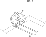
- Fig. 8 shows a perspective view diagram that explains an example of an arrangement of coils and line units in a high-frequency magnetic field generating device in Embodiment 6 of the present invention.
- the high-frequency magnetic field generating device in Embodiment 6 has a circuit configuration as described in Embodiment 1 or 2 (i.e. Fig. 2 or 3 ), and includes a circuit board 21.
- the two coils L1 and L2 are arranged on one surface of the circuit board 21 so as to be substantially perpendicular to this surface.
- the two line units S1 and S2 are wiring patterns, respectively, and are formed on any surface of the circuit board 21.
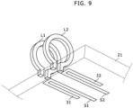
- Fig. 9 shows a perspective view diagram that explains another example of line units in a high-frequency magnetic field generating device in Embodiment 6 of the present invention.
- branch parts 31 and 32 identical to each other are formed in the line units S1 and S2, respectively. Consequently, using the branch parts 31 and 32, the current distribution can be adjusted in the coils L1 and L2 and the line units S1 and S2, and in addition, a width of input frequency band can be adjusted.
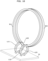
- Fig. 10 shows a perspective view diagram that explains an example of an arrangement of coils and line units in a high-frequency magnetic field generating device in Embodiment 7 of the present invention.
- the high-frequency magnetic field generating device in Embodiment 7 has a circuit configuration as described in Embodiment 4 (i.e. Fig. 5 ), and includes a circuit board 21.
- the coils L11, L12, L21 and L22 are arranged on the circuit board 21 so as to be perpendicular to the circuit board 21, the line unit S11 that has a partially-cutted-off ring shape is connected to an end of the coil L11 and an end of the coil L12, and the line unit S21 that has a partially-cutted-off ring shape is connected to an end of the coil L21 and an end of the coil L22.
- the line units S11 and S21 are arranged so as to be perpendicular to an opening direction of the coils L11 and L22 and an opening direction of the coils L12 and L21 (i.e. a direction of a magnetic field formed by the coils L11, L22, L12 and L21), such that magnetic coupling is restrained between (a) the coils L11, L22, L12 and L21 and (b) the line units S11 and S2.
- Fig. 11 shows a circuit diagram that indicates a configuration of a high-frequency magnetic field generating device in Embodiment 8 of the present invention.
- the two coils L1 and L2 are connected in parallel with each other, and one transmission line S1s as a transmission line part is connected to a connecting point between the two coils L1 and L2.
- the one transmission line S1s sets a current distribution so as to locate the two coils L1 and L2 at positions other than a node of a stationary wave.
- one end of the line unit S1s is open-circuited, and the other end of the line unit S1s is connected to one connecting point between the two coils L1 and L2.
- the high-frequency power supply 1 is connected to the other connecting point between the two coils L1 and L2. Therefore, microwave current flows from the high-frequency power supply 1 into the other-side ends of the two coils L1 and L2.
- the two coils L1 and L2 have identical shapes to each other. Consequently, in view from the high-frequency power supply 1, (a) the coil L1 and the line unit S1s and (b) the coil L2 and the line unit S1s have identical high frequency characteristics (i.e. identical electrical lengths) to each other.
- an electrical length of the coils L1 and L2 and the line unit S1s is LAMBDA/4 (LAMBDA: wavelength of the microwave)
- LAMBDA wavelength of the microwave
- Embodiment 8 instead of the configuration of the high-frequency magnetic field generating device shown in Fig. 11 , modification examples shown in Fig. 12 or 13 may be applied.
- Fig. 12 shows a circuit diagram that indicates a configuration of a high-frequency magnetic field generating device in a modification example #1 of Embodiment 8 of the present invention.
- one end of a variable capacitance element 41 is connected to one end of the line unit S1s such that this one end is not connected to the coils L1 and L2, and the other end of the variable capacitance element 41 is connected to a ground. Consequently, even if displacement appears between the central axes, a center of a resonance frequency band of the coils L1 and L2 can be adjusted by changing a capacitance of the variable capacitance element 41 so as to cause the center of a resonance frequency band to get closest to a desired frequency.
- variable capacitance element 41 may be a device that moves a position of a part of the line unit S1s a little.
- the variable capacitance element 41 may be a variable capacitor that has a small capacitance, for example.
- Fig. 13 shows a circuit diagram that indicates a configuration of a high-frequency magnetic field generating device in a modification example #2 of Embodiment 8 of the present invention.
- one end of a variable capacitance element 51 is connected to one-side ends (i.e. the ends on the power supply side) of the coils L1 and L2 such that the one-side ends are not connected to the line unit S1s, and the other end of the variable capacitance element 51 is connected to a ground.
- variable capacitance element 51 may be (a) a variable capacitor that has a small capacitance, for example, (b) a device that moves a part of a conductive line between the power supply and the coils L1 and L2, or the like.
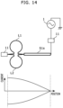
- Fig. 14 shows a circuit diagram that indicates a configuration of a high-frequency magnetic field generating device in Embodiment 9 of the present invention.
- the two coils L1 and L2 are connected in parallel with each other, and one transmission line S1s as a transmission line part is connected to a connecting point between the two coils L1 and L2.
- the one transmission line S1s sets a current distribution so as to locate the two coils L1 and L2 at positions other than a node of a stationary wave.
- one end of the line unit S1s is connected through a first impedance matching unit 11 to the high-frequency power supply 1, and the other end of the line unit S1s is connected to one connecting point between the two coils L1 and L2.
- one end of a second impedance matching unit 11 is connected to the other connecting point between the two coils L1 and L2.
- the other end of the second impedance matching unit 11 is open-circuited. Therefore, microwave current flows from the high-frequency power supply 1 through the first impedance matching unit 11 and the line unit S1s to the ends of the two coils L1 and L2.
- the two coils L1 and L2 have identical shapes to each other. Consequently, in view from the high-frequency power supply 1, (a) the coil L1 and the line unit S1s and (b) the coil L2 and the line unit S1s have identical high frequency characteristics (i.e. identical electrical lengths) to each other.
- an electrical length of the coils L1 and L2 and the line unit S1s is LAMBDA/4 (LAMBDA: wavelength of the microwave)
- LAMBDA wavelength of the microwave
- Fig. 15 shows a circuit diagram that indicates a configuration of a high-frequency magnetic field generating device in Embodiment 10 of the present invention.
- the two coils L1 and L2 are connected in parallel with each other, and transmission lines S1s as a transmission line part are connected to connecting points between the two coils L1 and L2, respectively.
- the transmission lines S1s set a current distribution so as to locate the two coils L1 and L2 at positions other than a node of a stationary wave.
- one end of the first line unit S1s is connected through a first impedance matching unit 11 to the high-frequency power supply 1, and the other end of the first line unit S1s is connected to one connecting point between the two coils L1 and L2.
- one end of a second line unit S1s is connected to the other connecting point between the two coils L1 and L2.
- the other end of the second line unit S1s is connected to one end of a second impedance matching unit 11.
- the other end of the second impedance matching unit 11 is open-circuited.
- microwave current flows from the high-frequency power supply 1 through the first impedance matching unit 11 and the first line unit S1s to the ends of the two coils L1 and L2.
- the two coils L1 and L2 have identical shapes to each other, and the line units S1s also have identical shapes to each other. Consequently, in view from the high-frequency power supply 1, (a) the coil L1 and the line units S1s and (b) the coil L2 and the line units S1s have identical high frequency characteristics (i.e. identical electrical lengths) to each other.
- an electrical length of the coils L1 and L2 and the line units S1s is LAMBDA/2 (LAMBDA: wavelength of the microwave)
- LAMBDA wavelength of the microwave
- Fig. 16 shows a diagram that indicates a configuration of a high-frequency magnetic field generating device in Embodiment 11 of the present invention.
- the coils L1 and L2 are formed as metal patterns in parallel with each other on a front surface and a back surface of a circuit board 61 that has a predetermined thickness. Further, a penetrating hole 62 is formed so as to penetrate a center of the coils L1 and L2. This penetrating hole 62 enables the high-frequency alternate magnetic field to be applied to a sample not only (a) in a case that a pair of the coil L1 and L2 is arranged at one side from the sample with a predetermined distance but (b) in a case that the sample is arranged at any position between the coils L1 and L2 in the height direction.
- penetrating holes 63 and 64 may be formed in the wall thickness of the circuit board 61 so as to be parallel to a radius direction of the coils L1 and L2.
- a laser beam enters from the penetrating hole 63
- a sample (not shown) in the penetrating hole 62 is irradiated with the laser beam, and reflection light thereof passes through the penetrating hole 62 in an upward direction and/or a downward direction. Therefore, this reflection light can be detected by a microscope.
- a part of the laser light beam passes through the sample and the part of the laser light beam exits through the penetrating hole 64. Therefore, the exiting part of the laser light beam may be observed.
- a diameter of the penetrating hole 64 may be larger than a diameter of the penetrating hole 63.
- the circuit board 61 is arranged in between the coils L1 and L2 in parallel, and therefore, an advantageous mechanical characteristic and an advantageous electrical characteristic are obtained from various viewpoints such as stable forming of shapes of the coils L1 and L2 and keeping a stable distance between the coils L1 and L2.
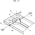
- Fig. 17 shows a diagram that indicates a configuration of a high-frequency magnetic field generating device in Embodiment 12 of the present invention.
- the high-frequency magnetic field generating device includes a plate coil La instead of the aforementioned coils L1 and L2 described in Embodiment 11.
- a penetrating hole 82 is formed in a circuit board 81 that has a predetermined thickness.
- the plate coil La is arranged in the penetrating hole 82.
- the plate coil La is fixed on an inner wall facing the penetrating hole 82 of the circuit board 81 such that a longitudinal direction of a cross section of the plate coil La is perpendicular to the circuit board 81.
- the cross section of the plate coil La has a substantially rectangle shape.
- the penetrating hole 82 may be a through hole; and the plate coil La may be a member formed by flexing and/or bending a thin metal plate such as copper plate or may be a metal foil formed on an inner circumferential surface of the through hole as the penetrating hole 82 using metal plating or the like.
- the penetrating hole 82 includes an observation hole part 82a of which a cross section has a circular shape.
- edge line parts LaEU and LaEL in particular, edge line parts in the observation hole part 82a) of the plate coil La
- edge line parts LaEU in a top end side and (b) one of edge line parts LaEL in a bottom end side act as two coils arranged with a predetermined gap in parallel with each other, and these two coils are arranged (a) in between which electron spin resonance material is arranged or (b) arranged at one side from electron spin resonance material.
- the edge line part LaEU in the top end side and the edge line part LaEL in the bottom end side substantially act as individual coils.
- a height of the plate coil La i.e. a length of a long side of the cross section
- a width of the plate coil La is set to be sufficiently smaller than the height of the plate coil La.
- This penetrating hole 82 enables the high-frequency alternate magnetic field to be applied to a sample not only (a) in a case that both of the edge line part LaEU in the top end side and the edge line part LaEL in the bottom end side are arranged at one side from the sample with a predetermined distance but (b) in a case that the sample is arranged at any position between the edge line part LaEU in the top end side and the edge line part LaEL in the bottom end side in the height direction.
- penetrating holes 83 and 84 may be formed in the wall thickness of the circuit board 81 so as to be parallel to a radius direction of the circular part of the plate coil La, and penetrating holes 85a and 85b of the plate coil La may be formed at positions on an extension line between the penetrating holes 83 and 84.
- a laser beam enters from the penetrating holes 83 and 85a, a sample (not shown) in the penetrating hole 82 is irradiated with the laser beam, and reflection light thereof passes through the penetrating hole 82 in an upward direction and/or a downward direction. Therefore, this reflection light can be detected by a microscope.
- diameters of the penetrating holes 85a and 84 may be larger than diameters of the penetrating holes 83 and 85a.
- Embodiment 12 Other parts of configuration and behaviors of the high-frequency magnetic field generating device in Embodiment 12 are identical or similar to those in Embodiment 9 or 11 or a combination thereof, and therefore not explained here.
- the aforementioned plate coil La is applied and thereby a direct-current resistance of the coil gets low. If there is a metallic object such as a housing of the microscope for observation or a dielectric object such as sample base around the coil, then the resonance frequency may change due to the existence of such object, but such change of the resonance frequency is restrained by applying the aforementioned plate coil La.
- the resonance frequency in Embodiment 12 was 2.96 GHz in a status that a sample was arranged in the penetrating hole 82 or 2.965 GHz in a status that a lens of the microscope was arranged at the distance of 1.5 mm.
- the resonance frequency was 2.84 GHz in a status that a sample was arranged in the penetrating hole or 2.89 GHz in a status that a lens of the microscope was arranged at the distance of 1.5 mm.
- Fig. 18 shows a diagram that indicates a configuration of a high-frequency magnetic field generating device in Embodiment 13 of the present invention.
- the penetrating hole 82 has a substantially rectangular shape, and the plate coil La is arranged in the penetrating hole 82.
- the plate coil La is fixed such that the plate coil La protrudes from an inner wall facing the penetrating hole 82 of the circuit board 81.
- Embodiment 13 Other parts of configuration and behaviors of the high-frequency magnetic field generating device in Embodiment 13 are identical or similar to those in Embodiment 12, and therefore not explained here.
- the ends of the aforementioned two line units may be neither open-circuited nor short-circuited, and may be terminated with a predetermined resistance value.
- the coils L11 and L21 may be removed and the line units S11 and S21 may be connected to each other, and the high-frequency power supply 1 may be connected to a connecting point between the line units S11 and S21.
- the line unit is used as the transmission line unit.
- the aforementioned line unit may be replaced with a lumped constant circuit if required.
- a diamond including an NVC is described as an example of the ODMR material.
- the ODMR material including another color center e.g. SiC color center or color center of ZnO, GaN, Si, an organic substance or the like
- the high-frequency power supply 1 generates microwave current having a frequency corresponding to the color center in use.
- the high-frequency magnetic field generating device can form a uniform magnetic field in an area substantially identical to an opening area of the coil. Therefore, in particular, the high-frequency magnetic field generating device is applied to ODMR in a high frequency range equal to or higher than 100 MHz, and in addition, the high-frequency magnetic field generating device may be applied to another measurement using electron spin resonance, such as EDMR.
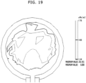
- Fig. 19 shows a diagram that indicates a result of a simulation of a magnetic field emitted from the high-frequency magnetic field generating device in Embodiment 6 of the present invention.
- This simulation is performed under a condition that current of about 3 GHz is supplied from a power supply to the coil L1 and L2, and the result shows that as shown in Fig. 19 , a uniform magnetic field (for example, a magnetic field area that has an error of 10 percent or less of the value of the magnetic field intensity at the center) are generated in a substantially whole area of the opening area from the center of the circular part of the coils L1 and L2.
- a uniform magnetic field for example, a magnetic field area that has an error of 10 percent or less of the value of the magnetic field intensity at the center
- a high-frequency magnetic field generating device in each embodiment of the present invention can be used as well as an ordinary coil-type resonator.
- the present invention is applicable to a high-frequency magnetic field generating device for Optically Detected Magnetic Resonance.
Landscapes
- Physics & Mathematics (AREA)
- General Physics & Mathematics (AREA)
- Condensed Matter Physics & Semiconductors (AREA)
- Power Engineering (AREA)
- Engineering & Computer Science (AREA)
- Chemical & Material Sciences (AREA)
- Life Sciences & Earth Sciences (AREA)
- Analytical Chemistry (AREA)
- Biochemistry (AREA)
- General Health & Medical Sciences (AREA)
- Immunology (AREA)
- Pathology (AREA)
- Health & Medical Sciences (AREA)
- High Energy & Nuclear Physics (AREA)
- Magnetic Resonance Imaging Apparatus (AREA)
Priority Applications (1)
| Application Number | Priority Date | Filing Date | Title |
|---|---|---|---|
| EP25205309.5A EP4647796A3 (de) | 2017-09-12 | 2018-08-31 | Vorrichtung zur erzeugung eines hochfrequenten magnetfeldes |
Applications Claiming Priority (3)
| Application Number | Priority Date | Filing Date | Title |
|---|---|---|---|
| JP2017174895 | 2017-09-12 | ||
| JP2018038182A JP7112652B2 (ja) | 2017-09-12 | 2018-03-05 | 高周波磁場発生装置 |
| EP18191872.3A EP3454053B1 (de) | 2017-09-12 | 2018-08-31 | Vorrichtung zum erzeugen eines hochfrequenten magnetfelds |
Related Parent Applications (2)
| Application Number | Title | Priority Date | Filing Date |
|---|---|---|---|
| EP18191872.3A Division-Into EP3454053B1 (de) | 2017-09-12 | 2018-08-31 | Vorrichtung zum erzeugen eines hochfrequenten magnetfelds |
| EP18191872.3A Division EP3454053B1 (de) | 2017-09-12 | 2018-08-31 | Vorrichtung zum erzeugen eines hochfrequenten magnetfelds |
Related Child Applications (2)
| Application Number | Title | Priority Date | Filing Date |
|---|---|---|---|
| EP25205309.5A Division EP4647796A3 (de) | 2017-09-12 | 2018-08-31 | Vorrichtung zur erzeugung eines hochfrequenten magnetfeldes |
| EP25205309.5A Division-Into EP4647796A3 (de) | 2017-09-12 | 2018-08-31 | Vorrichtung zur erzeugung eines hochfrequenten magnetfeldes |
Publications (3)
| Publication Number | Publication Date |
|---|---|
| EP4414733A2 true EP4414733A2 (de) | 2024-08-14 |
| EP4414733A3 EP4414733A3 (de) | 2025-02-05 |
| EP4414733B1 EP4414733B1 (de) | 2026-01-14 |
Family
ID=63452477
Family Applications (3)
| Application Number | Title | Priority Date | Filing Date |
|---|---|---|---|
| EP25205309.5A Pending EP4647796A3 (de) | 2017-09-12 | 2018-08-31 | Vorrichtung zur erzeugung eines hochfrequenten magnetfeldes |
| EP24185109.6A Active EP4414733B1 (de) | 2017-09-12 | 2018-08-31 | Vorrichtung zur erzeugung eines hochfrequenten magnetfeldes |
| EP18191872.3A Active EP3454053B1 (de) | 2017-09-12 | 2018-08-31 | Vorrichtung zum erzeugen eines hochfrequenten magnetfelds |
Family Applications Before (1)
| Application Number | Title | Priority Date | Filing Date |
|---|---|---|---|
| EP25205309.5A Pending EP4647796A3 (de) | 2017-09-12 | 2018-08-31 | Vorrichtung zur erzeugung eines hochfrequenten magnetfeldes |
Family Applications After (1)
| Application Number | Title | Priority Date | Filing Date |
|---|---|---|---|
| EP18191872.3A Active EP3454053B1 (de) | 2017-09-12 | 2018-08-31 | Vorrichtung zum erzeugen eines hochfrequenten magnetfelds |
Country Status (3)
| Country | Link |
|---|---|
| US (4) | US10921413B2 (de) |
| EP (3) | EP4647796A3 (de) |
| CN (4) | CN114779139B (de) |
Families Citing this family (6)
| Publication number | Priority date | Publication date | Assignee | Title |
|---|---|---|---|---|
| CN114779139B (zh) * | 2017-09-12 | 2025-05-27 | 胜美达集团株式会社 | 高频磁场产生装置 |
| JP7265699B2 (ja) * | 2019-02-22 | 2023-04-27 | スミダコーポレーション株式会社 | 測定装置 |
| JP7447844B2 (ja) * | 2021-02-23 | 2024-03-12 | 株式会社デンソー | 磁場発生装置およびそれを備えた磁気センサ |
| CN117099008A (zh) * | 2021-03-31 | 2023-11-21 | 住友电气工业株式会社 | 金刚石光磁传感器 |
| CN114360842B (zh) * | 2021-12-28 | 2022-11-22 | 中国人民解放军海军工程大学 | 一种应用于高功率微波源的轻型化周期性磁场线圈 |
| KR20240159398A (ko) * | 2023-04-28 | 2024-11-05 | (주)아이티시 | 전자기파 치료 장치 |
Citations (1)
| Publication number | Priority date | Publication date | Assignee | Title |
|---|---|---|---|---|
| JP2012110489A (ja) | 2010-11-24 | 2012-06-14 | Sumitomo Electric Ind Ltd | 磁気計測装置、及び、磁気センサ素子の製造方法 |
Family Cites Families (34)
| Publication number | Priority date | Publication date | Assignee | Title |
|---|---|---|---|---|
| JPS60161552A (ja) * | 1984-02-01 | 1985-08-23 | Hitachi Ltd | Νmr検査装置の静磁場強度分布測定方法 |
| JPS63118648A (ja) * | 1986-11-07 | 1988-05-23 | Jeol Ltd | ル−プギヤツプ共振器を備えた電子スピン共鳴装置 |
| JPS63231251A (ja) * | 1987-03-20 | 1988-09-27 | Hitachi Ltd | 電子スピン共鳴装置 |
| US5024229A (en) * | 1987-11-16 | 1991-06-18 | The University Of Rochester | Resonators for magnetic resonance imaging |
| JPH0666908A (ja) * | 1992-08-13 | 1994-03-11 | Mitsubishi Electric Corp | Esr装置 |
| JP3310519B2 (ja) * | 1995-12-28 | 2002-08-05 | 日本電子株式会社 | ループギャップ共振器の共振周波数調整機構 |
| JPH10104181A (ja) * | 1996-09-27 | 1998-04-24 | Yamagata Pref Gov Technopolis Zaidan | 電子スピン共鳴の測定法および電子スピン共鳴測定装置 |
| GB2327762A (en) * | 1997-07-29 | 1999-02-03 | Marconi Gec Ltd | MRI magnet with shuttling HTSC prepolarising block |
| JP2001108732A (ja) * | 1999-10-07 | 2001-04-20 | Jeol Ltd | 電子スピン共鳴装置及び電子スピン共鳴装置用試料ホルダー |
| JP4672119B2 (ja) * | 2000-08-11 | 2011-04-20 | 株式会社東芝 | 核磁気共鳴映像装置用高周波コイル及び核磁気共鳴映像装置 |
| US6943550B2 (en) * | 2003-05-09 | 2005-09-13 | The University Of Hong Kong | High temperature superconductor tape RF coil for magnetic resonance imaging |
| DE102004024098B4 (de) * | 2004-05-14 | 2007-07-26 | Siemens Ag | Erzeuger zeitvariabler Magnetfelder für ein Magnetresonanzgerät und Magnetresonanzgerät mit einem derartigen Erzeuger zeitvariabler Magnetfelder |
| JP2006322755A (ja) * | 2005-05-17 | 2006-11-30 | Yamagata Promotional Organization For Industrial Technology | 電子スピン共鳴用コイル装置 |
| JP4745390B2 (ja) * | 2006-05-09 | 2011-08-10 | 株式会社日立製作所 | 磁気共鳴検査装置 |
| JP2008002933A (ja) * | 2006-06-22 | 2008-01-10 | Jeol Ltd | ループギャップ共振器 |
| DE102006045174A1 (de) * | 2006-09-25 | 2008-04-03 | Siemens Ag | Verfahren sowie Bildverarbeitungseinheit und medizinisches Bildaufnahmegerät zum Herstellen eines kontrastverbesserten Bilddatensatzes eines Untersuchungsbereichs eines Patienten |
| US7642779B2 (en) * | 2007-03-22 | 2010-01-05 | Kabushiki Kaisha Toshiba | MRI RF coil configured to decouple coil elements and MRI apparatus employing the same |
| DE102008007048B4 (de) * | 2008-01-31 | 2010-06-17 | Siemens Aktiengesellschaft | Dynamische Verzeichnungskorrektur bei EPI-Messungen in der medizinischen Magnet-Resonanz-Bildgebung |
| JP2010249761A (ja) * | 2009-04-20 | 2010-11-04 | Kobe Steel Ltd | Nmr用プローブ |
| US9036884B2 (en) * | 2009-09-17 | 2015-05-19 | Koninklijke Philips N.V. | Image intensity correction for magnetic resonance imaging |
| US8674550B2 (en) * | 2010-03-25 | 2014-03-18 | General Electric Company | Contactless power transfer system and method |
| US20130116544A1 (en) * | 2010-07-23 | 2013-05-09 | Koninklijke Philips Electronics N.V. | Dual pressure sensor signal chain to remove mutually-coupled mri interference |
| CN102958432B (zh) * | 2010-08-17 | 2015-06-10 | 株式会社日立医疗器械 | 高频线圈及使用了该高频线圈的磁共振摄像装置 |
| US9684044B2 (en) * | 2011-11-01 | 2017-06-20 | Hitachi, Ltd. | Magnetic resonance imaging apparatus and antenna device |
| US9971001B2 (en) * | 2011-11-28 | 2018-05-15 | The Texas A&M University System | Volume array coil with enforced uniform element currents for improved excitation homogeneity |
| JPWO2013128518A1 (ja) * | 2012-02-29 | 2015-07-30 | 日本電気株式会社 | 送電装置、受電装置、電力供給システム及び電子機器 |
| JP5811272B2 (ja) * | 2012-03-28 | 2015-11-11 | 富士通株式会社 | 送電装置 |
| CN103105599B (zh) * | 2012-05-29 | 2014-12-31 | 辽宁开普医疗系统有限公司 | 具有高速串行接口的磁共振接收线圈 |
| US9689954B2 (en) * | 2012-09-28 | 2017-06-27 | William Marsh Rice University | Intergrated electron spin resonance spectrometer |
| JP2014197937A (ja) * | 2013-03-29 | 2014-10-16 | 沖電気工業株式会社 | 非接触電力送信装置、非接触電力伝送システム、及び自動取引装置 |
| US10234518B2 (en) * | 2014-02-21 | 2019-03-19 | Children's Hospital Medical Center | Loop coil with integrated balun for MR applications |
| US10677953B2 (en) * | 2016-05-31 | 2020-06-09 | Lockheed Martin Corporation | Magneto-optical detecting apparatus and methods |
| CN114779139B (zh) * | 2017-09-12 | 2025-05-27 | 胜美达集团株式会社 | 高频磁场产生装置 |
| CN208422213U (zh) * | 2018-01-10 | 2019-01-22 | 上海复旦天欣科教仪器有限公司 | 微波电子自旋共振实验装置 |
-
2018
- 2018-08-14 CN CN202210448222.4A patent/CN114779139B/zh active Active
- 2018-08-14 CN CN202210448664.9A patent/CN114779140B/zh active Active
- 2018-08-14 CN CN201810921098.2A patent/CN109490804B/zh active Active
- 2018-08-14 CN CN202210448981.0A patent/CN114779141B/zh active Active
- 2018-08-14 US US16/103,356 patent/US10921413B2/en active Active
- 2018-08-31 EP EP25205309.5A patent/EP4647796A3/de active Pending
- 2018-08-31 EP EP24185109.6A patent/EP4414733B1/de active Active
- 2018-08-31 EP EP18191872.3A patent/EP3454053B1/de active Active
-
2021
- 2021-01-07 US US17/143,630 patent/US11668778B2/en active Active
-
2023
- 2023-04-24 US US18/306,109 patent/US12248049B2/en active Active
-
2025
- 2025-02-04 US US19/044,750 patent/US20250189610A1/en active Pending
Patent Citations (1)
| Publication number | Priority date | Publication date | Assignee | Title |
|---|---|---|---|---|
| JP2012110489A (ja) | 2010-11-24 | 2012-06-14 | Sumitomo Electric Ind Ltd | 磁気計測装置、及び、磁気センサ素子の製造方法 |
Non-Patent Citations (1)
| Title |
|---|
| KENTO SASAKI: "Broadband, large-area microwave antenna for optically-detected magnetic resonance of nitrogen-vacancy centers in diamond", REVIEW OF SCIENTIFIC INSTRUMENTS, vol. 87, 2016, pages 053904, XP012208051, DOI: 10.1063/1.4952418 |
Also Published As
| Publication number | Publication date |
|---|---|
| CN114779139B (zh) | 2025-05-27 |
| EP3454053B1 (de) | 2024-10-02 |
| CN114779139A (zh) | 2022-07-22 |
| US20250189610A1 (en) | 2025-06-12 |
| US20210199744A1 (en) | 2021-07-01 |
| EP4647796A2 (de) | 2025-11-12 |
| EP3454053A1 (de) | 2019-03-13 |
| CN109490804A (zh) | 2019-03-19 |
| US10921413B2 (en) | 2021-02-16 |
| CN114779140B (zh) | 2025-03-18 |
| US12248049B2 (en) | 2025-03-11 |
| CN109490804B (zh) | 2022-05-31 |
| CN114779141B (zh) | 2025-05-23 |
| EP4414733B1 (de) | 2026-01-14 |
| EP4647796A3 (de) | 2026-01-21 |
| EP4414733A3 (de) | 2025-02-05 |
| US20230258755A1 (en) | 2023-08-17 |
| US20190079157A1 (en) | 2019-03-14 |
| CN114779140A (zh) | 2022-07-22 |
| CN114779141A (zh) | 2022-07-22 |
| US11668778B2 (en) | 2023-06-06 |
Similar Documents
| Publication | Publication Date | Title |
|---|---|---|
| US12248049B2 (en) | High-frequency magnetic field generating device | |
| JP7112652B2 (ja) | 高周波磁場発生装置 | |
| EP0112361B1 (de) | Hochfrequenzsonde und verfahren zur verwendung einer solchen | |
| US10502797B2 (en) | Crossed-loop resonators | |
| CN111610475A (zh) | 测量装置 | |
| JP2019153978A (ja) | 軌道角運動量モード擬似進行波共振器及び軌道角運動量アンテナ装置 | |
| US11500186B2 (en) | Combined microscope objective and microwave wire for optically detected magnetic resonance imaging | |
| RU2457588C1 (ru) | Детектор свч | |
| US8125226B2 (en) | Millipede surface coils | |
| JPH0810241A (ja) | 磁気共鳴装置用高周波アンテナ | |
| Watkins | Radiation Loss from Open-Circuited Dielectric Resonators (Short Papers) | |
| RU2251178C2 (ru) | Способ увеличения действующей высоты малогабаритного антенного устройства с управляемой диаграммой направленности и малогабаритное антенное устройство для осуществления способа | |
| JP6636336B2 (ja) | チップレスrfidタグのタグ情報読み取り回路 | |
| CN110470962A (zh) | 霍尔离子源励磁线圈绝缘老化程度的评估方法 | |
| JP2006177866A (ja) | 誘電定数測定方法 | |
| EP4673733A1 (de) | Sensoreinheit und resonatorschaltung dafür | |
| JP5118319B2 (ja) | 空洞共振器、及びそれを用いた電子スピン共鳴測定装置 | |
| SU1109675A1 (ru) | Устройство дл калибровки магнитных антенн | |
| JP2025120115A (ja) | 1つ以上のループギャップ共振器を含む共振器のキャビティ内に電磁エネルギーを結合するための装置及び方法 | |
| CN116908534A (zh) | 一种电容测量和筛选系统、电容容值筛选以及测量方法 | |
| Karkari et al. | Design and performance of a floating hairpin resonance probe for measuring plasma density in radio-frequency discharges |
Legal Events
| Date | Code | Title | Description |
|---|---|---|---|
| PUAI | Public reference made under article 153(3) epc to a published international application that has entered the european phase |
Free format text: ORIGINAL CODE: 0009012 |
|
| STAA | Information on the status of an ep patent application or granted ep patent |
Free format text: STATUS: THE APPLICATION HAS BEEN PUBLISHED |
|
| AC | Divisional application: reference to earlier application |
Ref document number: 3454053 Country of ref document: EP Kind code of ref document: P |
|
| AK | Designated contracting states |
Kind code of ref document: A2 Designated state(s): AL AT BE BG CH CY CZ DE DK EE ES FI FR GB GR HR HU IE IS IT LI LT LU LV MC MK MT NL NO PL PT RO RS SE SI SK SM TR |
|
| REG | Reference to a national code |
Ref country code: DE Ref legal event code: R079 Free format text: PREVIOUS MAIN CLASS: G01R0033360000 Ref country code: DE Ref legal event code: R079 Ref document number: 602018088670 Country of ref document: DE Free format text: PREVIOUS MAIN CLASS: G01R0033360000 Ipc: G01N0024100000 |
|
| PUAL | Search report despatched |
Free format text: ORIGINAL CODE: 0009013 |
|
| AK | Designated contracting states |
Kind code of ref document: A3 Designated state(s): AL AT BE BG CH CY CZ DE DK EE ES FI FR GB GR HR HU IE IS IT LI LT LU LV MC MK MT NL NO PL PT RO RS SE SI SK SM TR |
|
| RIC1 | Information provided on ipc code assigned before grant |
Ipc: G01R 33/36 20060101ALI20250102BHEP Ipc: G01R 33/34 20060101ALI20250102BHEP Ipc: G01R 33/32 20060101ALI20250102BHEP Ipc: G01N 24/10 20060101AFI20250102BHEP |
|
| STAA | Information on the status of an ep patent application or granted ep patent |
Free format text: STATUS: REQUEST FOR EXAMINATION WAS MADE |
|
| 17P | Request for examination filed |
Effective date: 20250320 |
|
| GRAP | Despatch of communication of intention to grant a patent |
Free format text: ORIGINAL CODE: EPIDOSNIGR1 |
|
| STAA | Information on the status of an ep patent application or granted ep patent |
Free format text: STATUS: GRANT OF PATENT IS INTENDED |
|
| RIC1 | Information provided on ipc code assigned before grant |
Ipc: G01N 24/10 20060101AFI20250724BHEP Ipc: G01R 33/32 20060101ALI20250724BHEP Ipc: G01R 33/34 20060101ALI20250724BHEP Ipc: G01R 33/36 20060101ALI20250724BHEP |
|
| INTG | Intention to grant announced |
Effective date: 20250806 |
|
| GRAS | Grant fee paid |
Free format text: ORIGINAL CODE: EPIDOSNIGR3 |
|
| GRAA | (expected) grant |
Free format text: ORIGINAL CODE: 0009210 |
|
| STAA | Information on the status of an ep patent application or granted ep patent |
Free format text: STATUS: THE PATENT HAS BEEN GRANTED |
|
| RAP3 | Party data changed (applicant data changed or rights of an application transferred) |
Owner name: SUMIDA CORPORATION |
|
| AC | Divisional application: reference to earlier application |
Ref document number: 3454053 Country of ref document: EP Kind code of ref document: P |
|
| AK | Designated contracting states |
Kind code of ref document: B1 Designated state(s): AL AT BE BG CH CY CZ DE DK EE ES FI FR GB GR HR HU IE IS IT LI LT LU LV MC MK MT NL NO PL PT RO RS SE SI SK SM TR |
|
| REG | Reference to a national code |
Ref country code: CH Ref legal event code: F10 Free format text: ST27 STATUS EVENT CODE: U-0-0-F10-F00 (AS PROVIDED BY THE NATIONAL OFFICE) Effective date: 20260114 Ref country code: GB Ref legal event code: FG4D |
|
| REG | Reference to a national code |
Ref country code: DE Ref legal event code: R096 Ref document number: 602018088670 Country of ref document: DE |
|
| REG | Reference to a national code |
Ref country code: IE Ref legal event code: FG4D |