EP4414518A1 - Vordach mit markise - Google Patents
Vordach mit markise Download PDFInfo
- Publication number
- EP4414518A1 EP4414518A1 EP24154608.4A EP24154608A EP4414518A1 EP 4414518 A1 EP4414518 A1 EP 4414518A1 EP 24154608 A EP24154608 A EP 24154608A EP 4414518 A1 EP4414518 A1 EP 4414518A1
- Authority
- EP
- European Patent Office
- Prior art keywords
- awning
- roller
- canopy
- side beam
- rolling
- Prior art date
- Legal status (The legal status is an assumption and is not a legal conclusion. Google has not performed a legal analysis and makes no representation as to the accuracy of the status listed.)
- Granted
Links
Images

Classifications
-
- E—FIXED CONSTRUCTIONS
- E04—BUILDING
- E04F—FINISHING WORK ON BUILDINGS, e.g. STAIRS, FLOORS
- E04F10/00—Sunshades, e.g. Florentine blinds or jalousies; Outside screens; Awnings or baldachins
- E04F10/02—Sunshades, e.g. Florentine blinds or jalousies; Outside screens; Awnings or baldachins of flexible canopy materials, e.g. canvas ; Baldachins
- E04F10/06—Sunshades, e.g. Florentine blinds or jalousies; Outside screens; Awnings or baldachins of flexible canopy materials, e.g. canvas ; Baldachins comprising a roller-blind with means for holding the end away from a building
- E04F10/0607—Sunshades, e.g. Florentine blinds or jalousies; Outside screens; Awnings or baldachins of flexible canopy materials, e.g. canvas ; Baldachins comprising a roller-blind with means for holding the end away from a building with guiding-sections for supporting the movable end of the blind
Definitions
- the present invention relates to a canopy with awning.
- the invention is intended for a canopy with a load-bearing structure, which is provided with at least two parallel beams, at least a front beam and rear beam, which are connected to each other by means of side beams.
- An awning is usually provided at the top of the load-bearing structure. If relevant the load-bearing structure is also covered with glass panels or the like. This, however, is not necessary. In some cases rainwater drainage is possible exclusively with the awning.
- a first side of an awning is attached to a roller that is rotatably applied in a screen casing located under or in the rear beam.
- the rear beam of such canopy is mounted against or to the façade of a building.
- a second side of the awning is attached to a so-called end bar.
- the side beams are provided with grooves for the lateral guidance of the end bar and free side edges of the awning.
- roller is applied in the rear beam is that a higher and wider profile is needed there.
- the purpose of the present invention is to provide a solution to the aforementioned and other disadvantages.
- the invention relates to a canopy with awning, whereby the canopy comprises a load-bearing structure with at least two parallel beams, i.e. a front beam and a rear beam, which are connected to each other by means of side beams, whereby the rear beam is intended for mounting against or to the façade of a building, whereby in at least one side beam a first roller is provided to which one end of the awning is attached and whereby at the facing end of the awning an end bar is provided, the ends of which are guided using guides provided at each of the at least two parallel beams for guiding the end bar from the side beam with the first roller to the facing side beam when rolling up and rolling out the awning whereby in at least one side beam a second roller is provided to which one end of the awning is attached and whereby at the facing end of the awning an end bar is provided which rolls out toward the ground from the side beam with the second roller or the other way around when rolling up the awning.
- a first roller is provided to which one end of the awning is attached and where
- the advantage of such canopy with awning according to the invention is that the space under the canopy can be blacked out in a strip that extends in a parallel way relative to the side beams.
- a shaded zone and a sunny zone can be created as it were which extend over the full depth of the canopy, or in other words, over the full length of the side beams.
- the surface or space under the canopy can be divided more simply into a use area with, for example, a seating area and an area that may remain lit, for example a corner for plants that require or tolerate a lot of sunshine.
- Another advantage is that by incorporating the first roller in the side beam, a high rear beam or space under the rear beam for a screen casing is no longer needed.
- the side beams already have a high profile anyway for bearing the weight of the panels and any snow load and in this way said space in the side beam can be efficiently utilised.
- the side beam in which the first roller is incorporated is provided with a removable cover plate.
- the first roller is easily accessible for mounting, inspection and maintenance.
- a second roller is provided in at least one side beam to which one end of the awning is attached and whereby at the facing end of the awning an end bar is provided. Said end bar rolls out from the side beam with the second roller towards the ground or the other way around when rolling up the awning.
- the second roller is positioned vertically above the first roller.
- the free height of the side beam, between the upperside of the side beam and the awning can be optimally utilised for applying panels, for example.
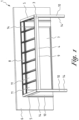
- the canopy 1 with awning 2 shown in figure 1 comprises a load-bearing structure 3 with in this case two parallel beams 4 which are connected to each other by means of two side beams 5.
- One of the two parallel beams 4 is mounted against or to the façade 6 of a building in which, in this case, a sliding window 7 is mounted.
- Said bar 4 is called the rear beam 8
- the facing bar 4 is called the front beam 9.
- this embodiment shows four vertical posts 10 on the four corners of the load-bearing structure 3 the invention is not limited to this.
- a series of glass panels 11 extend between the beams 4 in this case.
- this may also be other panels such as, for example, polycarbonate panels or sandwich panels.
- the vertical sides between the posts 10 of the canopy 1 and/or between the façade 6 and a post 10 of the canopy 1 can also be provided with glass panels 11, windows, sliding panels, awnings or the like or alternatively can also be open as shown in this figure 1 .
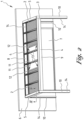
- FIG. 2 shows that in this case each of the two side beams 5 is provided with an awning 2 whereby at one end of each awning 2 an end bar 12 is provided, the ends of which are 13 guided in or by guides 14 provided on, or integrated in, the front beam 9 and rear beam 8.
- the two awnings 2 thus roll out toward each other, whereby the end bars 12 can meet, and roll up away from each other.
- the space or the surface under the canopy 1 is approximately evenly divided in this case in two shaded zones and one sunny zone, whereby the zones extend in a parallel way relative to the side beams 5 and over the full depth of the canopy 1.
- awning 2 could be provided in one side beam 5, whereby the length of the awning 2 is equal to the full width of the canopy to in this way black out the entire canopy 1 or to be able to divide it into a shaded zone and sunny zone.
- the variant of figure 3 is also provided with awnings 2 which can shield the vertical sides between the posts 10 of the canopy 1 and can thus roll out toward the ground and roll up toward the load-bearing structure 3.
- One end of said awnings 2 is also provided with an end bar 12, whereby the end bar 12 and the free side edges of the awning 2 are guided by means of vertical guides 14 which are provided for this purpose in or to the posts 10 of the canopy 1.
- said vertical awnings 2 are also provided in the side beams 5, respectively the front beam 9.
- Figure 3 also shows that in this case the glass panels 11 or the glass roof are completely blacked out. Indeed, the two awnings 2 which extend in a parallel way relative to the front beam 9 and rear beam 8 are completely rolled out whereby the end bars 12 of said awnings 2 connect against each other.
- the variant shown here is also provided with an awning 2 that rolls out from the front beam 9 toward the ground.
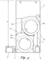
- the cross-section of the side beam 5 as shown in figure 4 shows two awnings 2 in this case which are each separately rolled up on respectively a first rotatable roller 15A and a second rotatable roller 15B, the side beam 5 acting as a shared screen casing 16 as it were for both the first roller 15A and the second roller 15B.
- each awning 2 is attached to the relevant roller 15A or 15B, whereas the facing end is connected to the end bar 12.
- the first roller 15A and second roller 15B are able to rotate around their axis for rolling up or rolling out the relevant awning 2.
- the rollers 15A and 15B are usually rotated by a drive coupled for this purpose to the axial ends of the rollers 15A and 15B and/or the end bar 12 by means of a belt or rope for example.
- the drive can also be located in a facing side beam 5 and pull the relevant awning 2 to the facing side beam 5 for rolling out the awning 2. Rolling up is then possible by means of a belt which is connected to the drive and the end bar 12 or alternatively by tensioning a torsion spring provided for that purpose when rolling out the awning 2.
- one awning 2 is intended for rolling out from the side beam 5 toward the ground using the second roller 15B and one awning 2 intended for rolling out from the side beam 5 toward the facing side beam 5 using the first roller 15A.
- the side beam 5 is executed in two halves 17A,17B.
- the first roller 15A is provided in the first half 17A, whereas the second roller 15B is provided in the second half 17B.
- Two halves 17A and 17B are understood to mean two parts that when composed, substantially form the side beam 5.
- first roller 15A and second roller 15B are also located vertically above each other for obtaining a high but narrow side beam 5.
- the second roller 15B is positioned vertically above the first roller 15A. Consequently a high space H remains between the awning 2 and the upperside of the side beam 5, whereby said space H can be used for applying panels 11 or the like, for example.
- the shared screen casing 16 is provided with a removable cover plate 18 through which the first roller 15A and/or second roller 15B are easily accessible for mounting, inspection and maintenance.
- only one awning 2 can be provided in one side beam 5. Whereby the length of said awning is such that the full width of the canopy can be blacked out.
Landscapes
- Engineering & Computer Science (AREA)
- Architecture (AREA)
- Civil Engineering (AREA)
- Structural Engineering (AREA)
- Building Awnings And Sunshades (AREA)
Applications Claiming Priority (1)
| Application Number | Priority Date | Filing Date | Title |
|---|---|---|---|
| BE20235095A BE1031332B1 (nl) | 2023-02-09 | 2023-02-09 | Overkapping met zonnescherm. |
Publications (3)
| Publication Number | Publication Date |
|---|---|
| EP4414518A1 true EP4414518A1 (de) | 2024-08-14 |
| EP4414518B1 EP4414518B1 (de) | 2025-10-01 |
| EP4414518C0 EP4414518C0 (de) | 2025-10-01 |
Family
ID=85277972
Family Applications (1)
| Application Number | Title | Priority Date | Filing Date |
|---|---|---|---|
| EP24154608.4A Active EP4414518B1 (de) | 2023-02-09 | 2024-01-30 | Vordach mit markise |
Country Status (2)
| Country | Link |
|---|---|
| EP (1) | EP4414518B1 (de) |
| BE (1) | BE1031332B1 (de) |
Citations (5)
| Publication number | Priority date | Publication date | Assignee | Title |
|---|---|---|---|---|
| EP2789764A1 (de) * | 2013-04-08 | 2014-10-15 | Gibus S.p.A. | Außenmarkise und Verfahren zur Montage der Markise |
| US10145118B2 (en) * | 2014-01-10 | 2018-12-04 | Renson Sunprotection-Screens Nv | Screen device |
| BE1026974A1 (nl) * | 2019-01-17 | 2020-08-12 | Renson Sunprotection-Screens Nv | Weerbestendige terrasoverkapping met dwarse vloeistofafvoer |
| AU2021260177A1 (en) * | 2020-04-21 | 2022-11-17 | Renson Outdoor Nv | Terrace canopy |
| EP4124700A1 (de) * | 2021-07-28 | 2023-02-01 | Brustor, N.V. | Terrassendach |
-
2023
- 2023-02-09 BE BE20235095A patent/BE1031332B1/nl active IP Right Grant
-
2024
- 2024-01-30 EP EP24154608.4A patent/EP4414518B1/de active Active
Patent Citations (5)
| Publication number | Priority date | Publication date | Assignee | Title |
|---|---|---|---|---|
| EP2789764A1 (de) * | 2013-04-08 | 2014-10-15 | Gibus S.p.A. | Außenmarkise und Verfahren zur Montage der Markise |
| US10145118B2 (en) * | 2014-01-10 | 2018-12-04 | Renson Sunprotection-Screens Nv | Screen device |
| BE1026974A1 (nl) * | 2019-01-17 | 2020-08-12 | Renson Sunprotection-Screens Nv | Weerbestendige terrasoverkapping met dwarse vloeistofafvoer |
| AU2021260177A1 (en) * | 2020-04-21 | 2022-11-17 | Renson Outdoor Nv | Terrace canopy |
| EP4124700A1 (de) * | 2021-07-28 | 2023-02-01 | Brustor, N.V. | Terrassendach |
Also Published As
| Publication number | Publication date |
|---|---|
| EP4414518B1 (de) | 2025-10-01 |
| BE1031332A1 (nl) | 2024-09-12 |
| EP4414518C0 (de) | 2025-10-01 |
| BE1031332B1 (nl) | 2024-09-16 |
Similar Documents
| Publication | Publication Date | Title |
|---|---|---|
| EP4139539B1 (de) | Terrassenüberdachung | |
| EP1715117A2 (de) | Verstellbares Sonnensegel mit einer Plane | |
| EP4414518A1 (de) | Vordach mit markise | |
| DE102019008027A1 (de) | Sonnenschutz | |
| EP2119848A2 (de) | Fassade, insbesondere Holzfassade und Verkleidung für Gebäude | |
| EP3636850A1 (de) | Pergola | |
| EP4139530B1 (de) | Terrassenüberdachung | |
| EP4414517B1 (de) | Sonnensegel mit markise | |
| DE102020127238B3 (de) | Profilträger, Tragkonstruktion und Überdachung | |
| BE1028656A1 (de) | Profilträger, Tragkonstruktion und Überdachung | |
| EP1225286B1 (de) | Ausfahrbare Abdeckung für einen Vorplatz | |
| DE19643529A1 (de) | Rahmenelement mit flexibler Bespannung und Bauwerk aus derartigen Rahmenelementen | |
| DE20309960U1 (de) | Ganzverglasung an einem Bauwerk | |
| CN219794808U (zh) | 一种具有隐藏式防风卷帘的户外凉亭 | |
| DE102013014196A1 (de) | Aufzugschachtverkleidung für Fassadenaufzüge | |
| EP3892787A1 (de) | Verschiebbare veranda mit selbstentleerendem dach | |
| EP4696849A1 (de) | Dachlatte und lattenrost mit der lamelle | |
| GB2427880A (en) | Telescopic conservatory | |
| ES2295044T3 (es) | Techo de vidrio, en particular de un invernadero, con un sistema productor de sombra exterior. | |
| EP3133223A1 (de) | Terrassendach mit schwenkbarem vordach | |
| EP0838564A1 (de) | Rahmenelement mit flexibler Bespannung und gebäudeartiger Aufbau mit solchen Rahmenelementen | |
| DE19930963A1 (de) | Markise | |
| DE19524848A1 (de) | Modulare Freiflächenabdeckung | |
| DE29906739U1 (de) | Aufhängevorrichtung für ein verschiebbares Schließelement, insbesondere einen Schiebeladen, ein Schiebefenster, eine Schiebewand oder -tür, und eine Zwischenschiene hierfür | |
| AT9653U1 (de) | Sonnen- und regenschutzanordnung |
Legal Events
| Date | Code | Title | Description |
|---|---|---|---|
| PUAI | Public reference made under article 153(3) epc to a published international application that has entered the european phase |
Free format text: ORIGINAL CODE: 0009012 |
|
| STAA | Information on the status of an ep patent application or granted ep patent |
Free format text: STATUS: THE APPLICATION HAS BEEN PUBLISHED |
|
| AK | Designated contracting states |
Kind code of ref document: A1 Designated state(s): AL AT BE BG CH CY CZ DE DK EE ES FI FR GB GR HR HU IE IS IT LI LT LU LV MC ME MK MT NL NO PL PT RO RS SE SI SK SM TR |
|
| STAA | Information on the status of an ep patent application or granted ep patent |
Free format text: STATUS: REQUEST FOR EXAMINATION WAS MADE |
|
| 17P | Request for examination filed |
Effective date: 20250211 |
|
| GRAP | Despatch of communication of intention to grant a patent |
Free format text: ORIGINAL CODE: EPIDOSNIGR1 |
|
| STAA | Information on the status of an ep patent application or granted ep patent |
Free format text: STATUS: GRANT OF PATENT IS INTENDED |
|
| INTG | Intention to grant announced |
Effective date: 20250611 |
|
| GRAS | Grant fee paid |
Free format text: ORIGINAL CODE: EPIDOSNIGR3 |
|
| GRAA | (expected) grant |
Free format text: ORIGINAL CODE: 0009210 |
|
| STAA | Information on the status of an ep patent application or granted ep patent |
Free format text: STATUS: THE PATENT HAS BEEN GRANTED |
|
| AK | Designated contracting states |
Kind code of ref document: B1 Designated state(s): AL AT BE BG CH CY CZ DE DK EE ES FI FR GB GR HR HU IE IS IT LI LT LU LV MC ME MK MT NL NO PL PT RO RS SE SI SK SM TR |
|
| REG | Reference to a national code |
Ref country code: GB Ref legal event code: FG4D Ref country code: CH Ref legal event code: F10 Free format text: ST27 STATUS EVENT CODE: U-0-0-F10-F00 (AS PROVIDED BY THE NATIONAL OFFICE) Effective date: 20251001 |
|
| REG | Reference to a national code |
Ref country code: IE Ref legal event code: FG4D |
|
| REG | Reference to a national code |
Ref country code: DE Ref legal event code: R096 Ref document number: 602024000760 Country of ref document: DE |
|
| U01 | Request for unitary effect filed |
Effective date: 20251002 |
|
| U07 | Unitary effect registered |
Designated state(s): AT BE BG DE DK EE FI FR IT LT LU LV MT NL PT RO SE SI Effective date: 20251014 |
|
| U20 | Renewal fee for the european patent with unitary effect paid |
Year of fee payment: 3 Effective date: 20260128 |
|
| PG25 | Lapsed in a contracting state [announced via postgrant information from national office to epo] |
Ref country code: ES Free format text: LAPSE BECAUSE OF FAILURE TO SUBMIT A TRANSLATION OF THE DESCRIPTION OR TO PAY THE FEE WITHIN THE PRESCRIBED TIME-LIMIT Effective date: 20251001 |
|
| PG25 | Lapsed in a contracting state [announced via postgrant information from national office to epo] |
Ref country code: NO Free format text: LAPSE BECAUSE OF FAILURE TO SUBMIT A TRANSLATION OF THE DESCRIPTION OR TO PAY THE FEE WITHIN THE PRESCRIBED TIME-LIMIT Effective date: 20260101 |
|
| PG25 | Lapsed in a contracting state [announced via postgrant information from national office to epo] |
Ref country code: HR Free format text: LAPSE BECAUSE OF FAILURE TO SUBMIT A TRANSLATION OF THE DESCRIPTION OR TO PAY THE FEE WITHIN THE PRESCRIBED TIME-LIMIT Effective date: 20251001 |
|
| PG25 | Lapsed in a contracting state [announced via postgrant information from national office to epo] |
Ref country code: RS Free format text: LAPSE BECAUSE OF FAILURE TO SUBMIT A TRANSLATION OF THE DESCRIPTION OR TO PAY THE FEE WITHIN THE PRESCRIBED TIME-LIMIT Effective date: 20260101 |
|
| PG25 | Lapsed in a contracting state [announced via postgrant information from national office to epo] |
Ref country code: IS Free format text: LAPSE BECAUSE OF FAILURE TO SUBMIT A TRANSLATION OF THE DESCRIPTION OR TO PAY THE FEE WITHIN THE PRESCRIBED TIME-LIMIT Effective date: 20260201 |
|
| PG25 | Lapsed in a contracting state [announced via postgrant information from national office to epo] |
Ref country code: CZ Free format text: LAPSE BECAUSE OF FAILURE TO SUBMIT A TRANSLATION OF THE DESCRIPTION OR TO PAY THE FEE WITHIN THE PRESCRIBED TIME-LIMIT Effective date: 20251001 |
|
| PG25 | Lapsed in a contracting state [announced via postgrant information from national office to epo] |
Ref country code: PL Free format text: LAPSE BECAUSE OF FAILURE TO SUBMIT A TRANSLATION OF THE DESCRIPTION OR TO PAY THE FEE WITHIN THE PRESCRIBED TIME-LIMIT Effective date: 20251001 |