EP4411684A2 - Bekleidungswärmeregulierungssystem - Google Patents
Bekleidungswärmeregulierungssystem Download PDFInfo
- Publication number
- EP4411684A2 EP4411684A2 EP24182161.0A EP24182161A EP4411684A2 EP 4411684 A2 EP4411684 A2 EP 4411684A2 EP 24182161 A EP24182161 A EP 24182161A EP 4411684 A2 EP4411684 A2 EP 4411684A2
- Authority
- EP
- European Patent Office
- Prior art keywords
- apparel
- thermo
- regulatory system
- dimensionally stable
- tem
- Prior art date
- Legal status (The legal status is an assumption and is not a legal conclusion. Google has not performed a legal analysis and makes no representation as to the accuracy of the status listed.)
- Pending
Links
Images


Classifications
-
- A—HUMAN NECESSITIES
- A41—WEARING APPAREL
- A41D—OUTERWEAR; PROTECTIVE GARMENTS; ACCESSORIES
- A41D13/00—Professional, industrial or sporting protective garments, e.g. surgeons' gowns or garments protecting against blows or punches
- A41D13/002—Professional, industrial or sporting protective garments, e.g. surgeons' gowns or garments protecting against blows or punches with controlled internal environment
- A41D13/005—Professional, industrial or sporting protective garments, e.g. surgeons' gowns or garments protecting against blows or punches with controlled internal environment with controlled temperature
-
- A—HUMAN NECESSITIES
- A41—WEARING APPAREL
- A41D—OUTERWEAR; PROTECTIVE GARMENTS; ACCESSORIES
- A41D1/00—Garments
- A41D1/002—Garments adapted to accommodate electronic equipment
- A41D1/005—Garments adapted to accommodate electronic equipment with embedded cable or connector
-
- A—HUMAN NECESSITIES
- A41—WEARING APPAREL
- A41D—OUTERWEAR; PROTECTIVE GARMENTS; ACCESSORIES
- A41D13/00—Professional, industrial or sporting protective garments, e.g. surgeons' gowns or garments protecting against blows or punches
- A41D13/002—Professional, industrial or sporting protective garments, e.g. surgeons' gowns or garments protecting against blows or punches with controlled internal environment
- A41D13/0025—Professional, industrial or sporting protective garments, e.g. surgeons' gowns or garments protecting against blows or punches with controlled internal environment by means of forced air circulation
-
- A—HUMAN NECESSITIES
- A41—WEARING APPAREL
- A41D—OUTERWEAR; PROTECTIVE GARMENTS; ACCESSORIES
- A41D27/00—Details of garments or of their making
- A41D27/28—Means for ventilation
-
- A—HUMAN NECESSITIES
- A45—HAND OR TRAVELLING ARTICLES
- A45F—TRAVELLING OR CAMP EQUIPMENT: SACKS OR PACKS CARRIED ON THE BODY
- A45F5/00—Holders or carriers for hand articles; Holders or carriers for use while travelling or camping
- A45F5/02—Fastening articles to the garment
-
- A—HUMAN NECESSITIES
- A61—MEDICAL OR VETERINARY SCIENCE; HYGIENE
- A61B—DIAGNOSIS; SURGERY; IDENTIFICATION
- A61B5/00—Measuring for diagnostic purposes; Identification of persons
- A61B5/68—Arrangements of detecting, measuring or recording means, e.g. sensors, in relation to patient
- A61B5/6801—Arrangements of detecting, measuring or recording means, e.g. sensors, in relation to patient specially adapted to be attached to or worn on the body surface
- A61B5/6802—Sensor mounted on worn items
- A61B5/6804—Garments; Clothes
-
- F—MECHANICAL ENGINEERING; LIGHTING; HEATING; WEAPONS; BLASTING
- F25—REFRIGERATION OR COOLING; COMBINED HEATING AND REFRIGERATION SYSTEMS; HEAT PUMP SYSTEMS; MANUFACTURE OR STORAGE OF ICE; LIQUEFACTION SOLIDIFICATION OF GASES
- F25B—REFRIGERATION MACHINES, PLANTS OR SYSTEMS; COMBINED HEATING AND REFRIGERATION SYSTEMS; HEAT PUMP SYSTEMS
- F25B21/00—Machines, plants or systems, using electric or magnetic effects
- F25B21/02—Machines, plants or systems, using electric or magnetic effects using Peltier effect; using Nernst-Ettinghausen effect
- F25B21/04—Machines, plants or systems, using electric or magnetic effects using Peltier effect; using Nernst-Ettinghausen effect reversible
-
- F—MECHANICAL ENGINEERING; LIGHTING; HEATING; WEAPONS; BLASTING
- F25—REFRIGERATION OR COOLING; COMBINED HEATING AND REFRIGERATION SYSTEMS; HEAT PUMP SYSTEMS; MANUFACTURE OR STORAGE OF ICE; LIQUEFACTION SOLIDIFICATION OF GASES
- F25D—REFRIGERATORS; COLD ROOMS; ICE-BOXES; COOLING OR FREEZING APPARATUS NOT OTHERWISE PROVIDED FOR
- F25D31/00—Other cooling or freezing apparatus
- F25D31/005—Combined cooling and heating devices
-
- G—PHYSICS
- G08—SIGNALLING
- G08B—SIGNALLING SYSTEMS, e.g. PERSONAL CALLING SYSTEMS; ORDER TELEGRAPHS; ALARM SYSTEMS
- G08B21/00—Alarms responsive to a single specified undesired or abnormal condition and not otherwise provided for
- G08B21/02—Alarms for ensuring the safety of persons
- G08B21/04—Alarms for ensuring the safety of persons responsive to non-activity, e.g. of elderly persons
- G08B21/0438—Sensor means for detecting
- G08B21/0453—Sensor means for detecting worn on the body to detect health condition by physiological monitoring, e.g. electrocardiogram, temperature, breathing
-
- H—ELECTRICITY
- H10—SEMICONDUCTOR DEVICES; ELECTRIC SOLID-STATE DEVICES NOT OTHERWISE PROVIDED FOR
- H10N—ELECTRIC SOLID-STATE DEVICES NOT OTHERWISE PROVIDED FOR
- H10N19/00—Integrated devices, or assemblies of multiple devices, comprising at least one thermoelectric or thermomagnetic element covered by groups H10N10/00 - H10N15/00
-
- A—HUMAN NECESSITIES
- A41—WEARING APPAREL
- A41D—OUTERWEAR; PROTECTIVE GARMENTS; ACCESSORIES
- A41D1/00—Garments
- A41D1/002—Garments adapted to accommodate electronic equipment
-
- A—HUMAN NECESSITIES
- A61—MEDICAL OR VETERINARY SCIENCE; HYGIENE
- A61F—FILTERS IMPLANTABLE INTO BLOOD VESSELS; PROSTHESES; DEVICES PROVIDING PATENCY TO, OR PREVENTING COLLAPSING OF, TUBULAR STRUCTURES OF THE BODY, e.g. STENTS; ORTHOPAEDIC, NURSING OR CONTRACEPTIVE DEVICES; FOMENTATION; TREATMENT OR PROTECTION OF EYES OR EARS; BANDAGES, DRESSINGS OR ABSORBENT PADS; FIRST-AID KITS
- A61F7/00—Heating or cooling appliances for medical or therapeutic treatment of the human body
- A61F7/007—Heating or cooling appliances for medical or therapeutic treatment of the human body characterised by electric heating
- A61F2007/0075—Heating or cooling appliances for medical or therapeutic treatment of the human body characterised by electric heating using a Peltier element, e.g. near the spot to be heated or cooled
-
- F—MECHANICAL ENGINEERING; LIGHTING; HEATING; WEAPONS; BLASTING
- F25—REFRIGERATION OR COOLING; COMBINED HEATING AND REFRIGERATION SYSTEMS; HEAT PUMP SYSTEMS; MANUFACTURE OR STORAGE OF ICE; LIQUEFACTION SOLIDIFICATION OF GASES
- F25B—REFRIGERATION MACHINES, PLANTS OR SYSTEMS; COMBINED HEATING AND REFRIGERATION SYSTEMS; HEAT PUMP SYSTEMS
- F25B21/00—Machines, plants or systems, using electric or magnetic effects
- F25B21/02—Machines, plants or systems, using electric or magnetic effects using Peltier effect; using Nernst-Ettinghausen effect
-
- H—ELECTRICITY
- H10—SEMICONDUCTOR DEVICES; ELECTRIC SOLID-STATE DEVICES NOT OTHERWISE PROVIDED FOR
- H10N—ELECTRIC SOLID-STATE DEVICES NOT OTHERWISE PROVIDED FOR
- H10N10/00—Thermoelectric devices comprising a junction of dissimilar materials, i.e. devices exhibiting Seebeck or Peltier effects
- H10N10/10—Thermoelectric devices comprising a junction of dissimilar materials, i.e. devices exhibiting Seebeck or Peltier effects operating with only the Peltier or Seebeck effects
- H10N10/13—Thermoelectric devices comprising a junction of dissimilar materials, i.e. devices exhibiting Seebeck or Peltier effects operating with only the Peltier or Seebeck effects characterised by the heat-exchanging means at the junction
Definitions
- the present disclosure relates to an apparel thermo-regulatory system for actively cooling or heating a wearer when worn.
- Maintaining persons such that their core body temperature stays within a predetermined range is important for optimizing performance whether athletic or otherwise. However, this may be difficult with traditional apparel.
- aspects herein relate to an apparel thermo-regulatory system configured to promote recovery from athletic exercise and/or to actively heat or cool a wearer to help maintain the wearer in an optimal temperature range thus facilitating, for example, job performance and/or athletic performance.
- Apparel thermo-regulatory systems described herein may be suitable for a wide range of applications such as, for example, athletes, firefighters, first responders, military personnel, and the like. More specifically, aspects herein contemplate an apparel thermo-regulatory system that utilizes thermoelectric modules (otherwise known as thermoelectric coolers, Peltier chips or devices, thermoelectric units, thermoelectric chips, and the like) integrated into an apparel item using one or more attachment structures to heat or cool a wearer.
- thermoelectric modules otherwise known as thermoelectric coolers, Peltier chips or devices, thermoelectric units, thermoelectric chips, and the like
- thermoelectric module is a solid-state heat pump that utilizes electrical energy to transfer heat from a cold side to a hot side of the TEM against a temperature gradient, using the Peltier effect.
- heat is absorbed at the cold side by electrons as they pass from a low energy level in a p-type semiconductor element to a higher energy level in an n-type semiconductor element.
- a voltage differential between a positive connector and a negative connector of the TEM provides the electrical potential to move the electrons from the low energy level to the high energy level.
- energy in the form of heat is released as the electrons move from the higher energy level back to the low energy level.
- TEMs have the advantage of switching from cooling to heating by reversing the polarity of the electrical supply. Thus, what may have formerly been the cold side of the TEM may become the hot side, and what may have formerly been the hot side of the TEM may become the cold side after the polarity is reversed. Thus, a single TEM may be used to both heat and cool.
- aspects herein contemplate an apparel thermo-regulatory system that uses evaporative heat transfer to dissipate heat from the hot side of the TEM. More particularly, aspects herein contemplate harnessing the wearer's own sweat or perspiration to remove the heat from the hot side of the TEM. A number of different approaches may be used to transport sweat from a first part of an apparel item to a second part of the apparel item where one or more TEMs are located.
- Additional aspects of the apparel thermo-regulatory system contemplated herein comprise an attachment structure useable for attaching one or more devices, such as one or more TEMs to an apparel item.
- one or more devices such as one or more TEMs
- apparel items are generally formed of a flexible material, it may be challenging to attach more rigid structures, such as TEMs, to the apparel item without comprising the integrity, the physical characteristics (e.g., flexibility, pliability, drapability, and the like), and/or the functional characteristics (e.g., permeability, breathability, moisture-management characteristics, and the like) of the apparel item.
- Aspects herein contemplate a flexible, dimensionally stable frame integrated into the apparel item and configured to receive one or more devices such as TEMs.
- the dimensionally stable frame is integrated into the apparel item in such a way that it does not need to be removed prior to, for instance, washing. In this way, a wearer may don the apparel item, quickly attach the one or more devices to the integrated dimensionally stable frame, and begin, for example, working or exercising.
- the dimensionally stable frame comprises a first surface, a second surface opposite the first surface, and at least one aperture sized to receive a device such as a TEM.
- a device such as a TEM.
- the term "dimensionally stable" may be defined as a material that exhibits the property of being able to maintain its original dimensions while being used for its intended purpose.
- the first surface of the dimensionally stable frame is affixed to the outer-facing surface of the apparel item.
- an absorbent material may be applied to the second surface of the frame.
- the absorbent material may be used to collect perspiration and/or water and continually release it around the hot side of TEMs to help remove heat from the TEMs.
- the dimensionally stable frame may be perforated to enable perspiration located on the outer-facing surface of the apparel item to move through the dimensionally stable frame to the absorbent material.
- one or more TEMs may be positioned adjacent an inner-facing surface of the apparel item and releasably mated with the aperture of the dimensionally stable frame.
- the TEM may comprise a base portion having a first generally planar surface and a flange portion having a second generally planar surface opposite the first surface.
- the flange portion extends outward from the base portion to form a lip between the base portion and the flange portion.
- the aperture in the dimensionally stable frame may have an aperture size that is intermediate between the width of the base portion and that of the flange portion of the TEM.
- the flange portion When the flange portion is positioned within the aperture of the dimensionally stable frame and a degree of pressure is applied, the flange portion is forced through the aperture and the lip engages with the aperture edges to maintain the TEM within the frame.
- the TEM is inserted from an inner-facing side of the apparel item, and the dimensionally stable frame is affixed to the outer-facing side of the apparel item, a portion of the fabric of the apparel item covers the second surface of the TEM after it is mated with the aperture of the dimensionally stable frame. This may promote removal of heat from the TEM as explained more fully below.
- thermoelectric module array may comprise two or more TEMs that are physically and electrically coupled using a flexible substrate to which an electronic circuit is applied.
- a power supply unit may also be physically and electrically coupled to the TEMs using the flexible substrate.
- the flexible substrate may comprise an electrically insulating polyimide film such as Kapton ® .
- the TEM array may comprise six TEMs that are arranged radially around a seventh TEM to form a spoke-and-hub pattern. The polyimide film connects each of the six TEMs to the seventh TEM and may further connect the TEMs to a power supply unit such as a battery.
- TEMs arranged in a linear pattern, a staggered pattern, an auxetic pattern, and the like.
- the TEM array described herein may comprise additional components such as temperature sensors for detecting the surface temperature of a wearer's skin, microprocessors and controllers for cycling the TEMs from an off state to an on state, and the like.
- aspects herein are directed to an apparel thermo-regulatory system comprising an apparel item, the dimensionally stable frame described above, and the TEM array previously described.
- the apparel item may be formed of a wicking material.
- An exemplary wicking material may comprise Dri-FIT ® by Nike, Inc. These types of materials typically wick moisture from an inner-facing surface of the material to an outer-facing surface of the material where it can evaporate.
- the dimensionally stable frame may be applied to the outer-facing surface of the apparel item at one or more predetermined locations.
- the predetermined locations may correspond to high heat and/or sweat-producing areas of the human body as indicated by, for example, heat and sweat maps.
- the TEM array or other type of device array may be positioned adjacent to an inner-facing surface of the apparel item at the one or more predetermined locations, and the array may be releasably mated to the dimensionally stable frame.
- the first planar surface of the base portion of each TEM comprises the "cold" side of the TEM and the second planar surface of the flange portion comprises the "hot" side of the TEM.
- the cold side of each of the TEMs may be positioned adjacent to a skin surface of the wearer, and the hot side of each of the TEMs may be positioned opposite the skin surface of the wearer.
- the polarity of the opposing surfaces When used for heating, the polarity of the opposing surfaces may be reversed such that the first planar surface of the base portion comprises the "hot" side of the TEM and the second planar surface of the flange portion comprises the "cold” side of the TEM. Further, when used for recovery, the polarity of the opposing surfaces may be cycled according to a duty cycle such that, for example, the first planar surface alternates between a "cold" side and a "hot” side. Any and all aspects, and any variation thereof, are contemplated as being within aspects herein.
- the apparel item may comprise a compression or base layer.
- the wearer's body temperature may rise. Further, the wearer may begin sweating. Due to the apparel item being formed of, for example, a wicking material, the sweat may be transported from a skin-facing side of the apparel item to an outer-facing side of the apparel item. The sweat may then pass through the dimensionally stable frame via the perforations where it is then absorbed by the absorbent material present on the second surface of the frame. A continued rise in the wearer's body temperature may trigger the TEMs to start cycling on and off to help cool the wearer. As described, to improve the efficiency of the TEMs, the heat produced at the hot side of the TEM should be removed.
- the fabric is a wicking fabric, it may help to transport the perspiration collected in the absorbent material surrounding the TEMs to the hot side of the TEMs. Evaporation of the sweat from the absorbent material surrounding the TEMs and from the fabric positioned adjacent to the hot side of the TEMs helps to transfer heat from the hot side of the TEMs to the ambient environment.
- an attachment structure for attaching at least one device to an apparel item.
- the attachment structure comprises a dimensionally stable frame having a first surface and a second surface opposite the first surface, where the dimensionally stable frame having at least one aperture operable to receive the device, and where the first surface of the dimensionally stable frame is affixed to a first surface of the apparel item.
- the attachment structure further comprises an absorbent material applied to the second surface of the dimensionally stable frame.
- an attachment structure for attaching a plurality of devices to an apparel item.
- the attachment structure comprises a dimensionally stable frame having a first surface and a second surface opposite the first surface, where the dimensionally stable frame comprises a plurality of apertures, each aperture operable to receive a device.
- the first surface of the dimensionally stable frame is affixed to a first surface of the apparel item.
- an apparel item having an attachment structure for attaching at least one device to the apparel item comprises a flexible material that forms the apparel item, where the flexible material forms an outer-facing surface and an inner-facing surface of the apparel item.
- the apparel item further comprises a dimensionally stable frame formed of an absorbent material, where the dimensionally stable frame has a first surface and a second surface opposite the first surface. The first surface of the dimensionally stable frame is affixed to the outer-facing surface of the apparel item at a predetermined location on the apparel item, and the dimensionally stable frame comprises at least one aperture operable to receive the device.
- the apparel thermo-regulatory system comprises 1) an apparel item formed from a flexible material where the apparel item has an outer-facing surface and an inner-facing surface; 2) a dimensionally stable frame having a first surface and a second surface opposite the first surface, where the dimensionally stable frame comprises at least one aperture, and where the first surface of the dimensionally stable frame is affixed to the outer-facing surface of the apparel item at a predetermined location; 3) an absorbent material applied to the second surface of the dimensionally stable frame; and 4) at least one thermoelectric module having a first surface and a second surface opposite the first surface, where the first surface of the thermoelectric module is positioned adjacent to the inner-facing surface of the apparel item and is releasably positioned within the aperture of the dimensionally stable frame.
- thermoelectric module array comprising a plurality of thermoelectric modules, each having a first surface and a second surface opposite the first surface.
- the thermoelectric module array further comprises a flexible substrate having an electronic circuit applied thereto, wherein the flexible substrate is physically and electrically coupled to each of the plurality of thermoelectric modules.
- thermoelectric module array comprising a plurality of thermoelectric modules, each having a first surface and a second surface opposite the first surface.
- the thermoelectric module array further comprises a flexible substrate physically and electrically coupled to each of the plurality of thermoelectric modules; the flexible substrate comprising an electrically insulating layer having an electronic circuit applied thereto.
- thermoelectric module array positioned adjacent to the inner-facing surface of the apparel item and releasably coupled thereto, where the thermoelectric module array comprises: 1) a plurality of thermoelectric modules, each having a first surface and a second surface opposite the first surface; 2) a flexible substrate having an electronic circuit applied thereto, wherein the flexible substrate is physically and electrically coupled to each of the plurality of thermoelectric modules; and 3) a power supply unit electrically coupled to the flexible substrate.
- positional terms used when describing, for instance, an apparel item such as “anterior,” “posterior,” “inferior,” “superior,” “lateral,” “medial,” “inner-facing surface,” “outer-facing surface,” and the like are to be given their common meaning with respect to the apparel item being worn as intended by a hypothetical wearer standing in anatomical position.
- terms such as “affixed,” “coupled,” “secured,” and the like may mean releasably affixing two or more elements together using for instance, structural differences between the elements, releasable adhesives, snaps, buttons, hook-and-loop fasteners, and the like.
- proximate may mean within 0.5 cm to 30 cm of a designated reference point.
- the attachment structure may be used to attach one or more rigid-type devices to the textile.
- the term "devices” is meant to encompass devices such as TEMs, radio-frequency identification (RFID) tags, electronic devices such as physiological sensors (heart rate sensors, temperature sensors, respiratory sensors, sweat sensors, and the like), global positioning system (GPS) devices, monitoring devices, power supply units (e.g., batteries) or energy storage devices, lighting devices (e.g., electric light devices having light sources such as LEDs), and the like.
- RFID radio-frequency identification
- electronic devices such as physiological sensors (heart rate sensors, temperature sensors, respiratory sensors, sweat sensors, and the like), global positioning system (GPS) devices, monitoring devices, power supply units (e.g., batteries) or energy storage devices, lighting devices (e.g., electric light devices having light sources such as LEDs), and the like.
- power supply units e.g., batteries
- lighting devices e.g., electric light devices having light sources such as LEDs
- FIG. 1 depicts the textile layer 110 and an attachment structure in the form of a dimensionally stable frame 112.
- the textile layer 110 may be incorporated into an apparel item and, as such, may generally comprise a flexible material such as a knit or woven material.
- the textile layer 110 may comprise a wicking fabric configured to transport moisture from one surface of the textile layer 110 to a second opposite surface of the textile layer 110 using for instance, capillary action, denier differential mechanism, and the like.
- the frame 112 is formed of a flexible but dimensionally stable material.
- the frame 112 may comprise a thermoplastic polyurethane (TPU) film that may be optionally perforated onto which an optional absorbent material may be applied.
- TPU thermoplastic polyurethane
- Other materials for the dimensionally stable frame 112 are contemplated herein such as a polyurethane film, a plastic film, a non-woven material, a polystyrene film, a rubber film, a silicone film, a spandex material, and the like.
- the frame 112 may have a minimum thickness of 100 micrometers.
- the frame 112 may have a thickness of around 0.5 millimeters although thicknesses greater than this are contemplated herein.
- the absorbent material may comprise a hydrogel, a non-woven material such as a spacer mesh or a felt material, a knit pile material, a cellulosic or fiber-based product such as a sponge material, a superabsorbent polymer (SAP), combinations of these materials such as a hydrogel mixed with fibers, and the like.
- the absorbent material is configured to absorb water and/or sweat equal to at least five times its own volume.
- the absorbent material may be selected such that it releases water (either continuously or intermittently).
- the absorbent material is shown in more detail in FIG. 2 .
- the frame 112 may be formed from a dimensionally stable absorbent material without a TPU film layer. This is shown in more detail in FIG. 3 .
- Examples of a dimensionally stable absorbent material may comprise, for instance, a non-woven material such as a spacer mesh or a felt material although other dimensionally stable absorbent materials are contemplated herein.
- the frame 112 comprises a first surface (not shown) that is integrated into the textile layer 110 by being affixed to a first surface 114 of the textile layer 110. When incorporated into an apparel item, the first surface 114 of the textile layer 110 would form an outer-facing surface of the apparel item.
- the frame 112 further comprises a second surface 116.
- a plurality of apertures 118 each defined by an aperture edge 119 extend through the frame 112 but not through the textile layer 110 thus helping to maintain the structural integrity of the textile layer 110.
- the apertures 118 are shown as circular, it is contemplated herein that they may assume different shapes depending on the shape of the device that will be inserted into the apertures 118. For instance, if the device has a triangular profile, then the apertures 118 may have a triangular shape. Any and all aspects, and any variation thereof, are contemplated as being within aspects herein.
- an exemplary pattern of apertures 118 may comprise six apertures 118 radially arranged around a seventh, central aperture 118 in a spoke-and-hub pattern.
- Each aperture 118 may have a diameter 122 between 23.0 mm and 26.0 mm, between 23.3 mm and 25. 6 mm, and/or between 23.6 mm and 25.6 mm, although diameters above and below these values are contemplated herein.
- FIG. 2 illustrates an exploded view of one exemplary configuration of the attachment structure in accordance with aspects herein and is referenced generally by the numeral 200.
- FIG. 2 depicts a textile layer 210, a dimensionally stable frame 212, and an absorbent material 218.
- the textile layer 210 may comprise the textile layer 110 of FIG. 1 .
- the dimensionally stable frame 212 may be formed from, for instance, a flexible TPU or PU film.
- the frame 212 comprises a plurality of perforations 214 extending therethrough and apertures 216 extending therethrough.
- the apertures 216 may comprise the apertures 118 of FIG. 1 .
- the perforations 214 are smaller in size than the apertures 216 and may have diameters between, for instance, 1.0 mm and 5.0 mm.
- the perforations 214 may help perspiration or moisture present on the textile layer 110 to travel through the frame 212 to the absorbent material 218.
- apertures 220 may be formed in the absorbent material 218 or the absorbent material 218 may be formed to comprise the apertures 220.
- the absorbent material 218 comprises, for instance, a hydrogel or a SAP that may lack dimensional stability
- the absorbent material 218 may not comprise a separate layer having apertures 220, and instead, the absorbent material 218 may be directly applied to the frame 212.
- the frame 212 When the attachment structure is assembled, the frame 212 is applied to the surface of the textile layer 210 using for instance, a breathable adhesive, a discontinuous adhesive film (i.e., a film having one or more openings), an adhesive applied in a dot pattern, spot welding, and/or stitching or bonding along the perimeter of each so as not to occlude the perforations 214 and so as not to impede the passage of sweat or moisture from the textile layer 210 to the absorbent material 218.
- the frame 212 may be permanently affixed to the textile layer 210, and in other instances it is contemplated that the frame 212 may be releasably affixed to the textile layer 210.
- the absorbent material 218 when the absorbent material 218 exhibits dimensional stability, the absorbent material 218 may be permanently or releasably secured to the frame 212 such that the apertures 220 of the absorbent material 218 axially align with the apertures 216 of the frame 212. Securing the absorbent material 218 to the frame 212 may be through a breathable adhesive, a discontinuous adhesive film, an adhesive applied in a dot pattern, spot welding, and/or stitching or bonding along the perimeter of each so as not to occlude the perforations 214 and impede the passage of sweat or moisture from the textile layer 210 to the absorbent material 218. In those instances, where the absorbent material 218 is not dimensionally stable, the absorbent material 218 may be applied to the frame 212 via, for instance, a printing process, a spraying process, a transfer process, a manual application process, and the like.
- FIG. 3 depicts an exploded view of another exemplary configuration for an attachment structure in accordance with aspects herein and is referenced generally by the numeral 300.
- the configuration comprises a textile layer 310 which may comprise the textile layer 110 of FIG. 1 , and a dimensionally stable frame formed of a dimensionally stable absorbent material 312 such as, for example, a knit pile, a felt, a spacer mesh, other non-woven materials, and the like.
- Apertures 314, such as the apertures 118, may be formed through the absorbent material 312 or the absorbent material 312 may be pre-formed to comprise apertures 314.
- the dimensionally stable absorbent material 312 When assembled, the dimensionally stable absorbent material 312 is permanently or releasably applied to the textile layer 310 using, for example, a breathable adhesive, a discontinuous adhesive film, an adhesive applied in a dot pattern, spot welding, and/or stitching or bonding along the perimeter of each so as to permit the free passage of sweat or moisture on the textile layer 310 to the dimensionally stable absorbent material 312.
- a breathable adhesive for example, a breathable adhesive, a discontinuous adhesive film, an adhesive applied in a dot pattern, spot welding, and/or stitching or bonding along the perimeter of each so as to permit the free passage of sweat or moisture on the textile layer 310 to the dimensionally stable absorbent material 312.
- FIGs. 4A, 4B, and 5 depict yet another alternative configuration for the attachment structure in accordance with aspects herein.
- an absorbent material such as a hydrogel, a hydrogel mixed with fibers, or a SAP may be directly applied to a textile using for instance, a screen printing process, a 3-dimensional printing process, a transfer process, and the like.
- FIG. 4A depicts a first surface of a textile 400 to which an absorbent material 410 has been applied in an exemplary pattern.
- the first surface of the textile 400 may comprise an outer-facing surface of an apparel item when the textile 400 is used to form the apparel item. The pattern shown in FIG.
- the 4A may comprise lines 412 of absorbent material 410 which are thinner at the ends and thicker in the middle.
- the volume or quantity of absorbent material 410 may be greater at the middle of the lines 412 as compared to the ends of the lines 412.
- the lines 412 may be clustered into groups such as line groups 412a, 412b, and 412c.
- the lines 412 may not be clustered into groups and, instead, may be uniformly distributed on the textile 400.
- the hot side of a first TEM may be positioned adjacent to the line group 412a
- a hot side of a second TEM may be positioned adjacent to the line group 412b
- a hot side of a third TEM may be positioned adjacent to the line group 412c.
- the hot side of the TEM may be positioned adjacent to the middle of the lines 412 such that the greatest volume of absorbent material 410 is positioned adjacent to the hot side of the TEM.
- one or more TEMs may be positioned such that the greatest volume of absorbent material 410 is positioned adjacent to the hot side of the TEMs.
- FIG. 4B depicts a textile 450 to which an absorbent material 452 has been applied in an exemplary pattern.
- the pattern in this case comprises a series of intersecting lines clustered into groups such as group 454, group 456, group 458, and group 460. Similar to the pattern shown in FIG. 4A , the lines are generally thinner at each end and thicker in the middle. Because of the intersecting nature of the lines, the greatest volume or quantity of absorbent material 452 may be found at the center of each group 454, 456, 458, and 460.
- the intersecting lines may be distributed across the textile 450 with the greatest volume or quantity of the absorbent material 452 localized generally in the center of the interesting lines.
- the hot side of a first TEM may be positioned adjacent to the group 454
- a hot side of a second TEM may be positioned adjacent to the group 456
- a hot side of a third TEM may be positioned adjacent to the group 458, and
- a hot side of a fourth TEM may be positioned adjacent to the group 460.
- the hot side of the TEM may be positioned adjacent to the greatest volume of absorbent material 452 in each group 454, 456, 458, and 460.
- one or more TEMs may be positioned such that the greatest volume of absorbent material 452 is positioned adjacent to the hot side of the TEMs.
- the absorbent material patterns shown in FIGs. 4A and 4B are exemplary only and other patterns are contemplated herein. Additionally, the number of absorbent material groupings shown in these figures is exemplary only and a fewer or greater number of groupings is contemplated herein. Each of the absorbent material patterns contemplated herein generally comprise an area with a smaller volume of absorbent material that is contiguous with an area having a greater volume of absorbent material. The areas with a smaller amount of absorbent material may help to channel moisture or sweat to the areas with the greater volume of absorbent material where the moisture or sweat is concentrated and subsequently released.
- FIG. 5 referenced generally by the numeral 500, is provided to illustrate how the absorbent material patterns depicted in, for instance, FIGs. 4A and 4B may be utilized in association with an attachment structure for attaching TEMs to a flexible material. More specifically, FIG. 5 depicts a textile layer 510 and an absorbent material 512 applied to a first surface of the textile layer 510. As shown in FIGs. 4A and 4B , the absorbent material 512 may be thinner or have less volume at the periphery of the pattern and be thicker or have more volume at the central portion of the pattern as indicated by the reference numeral 513.
- a dimensionally stable frame 514 having an aperture 515 defined by aperture edges 516 may be applied to the first surface of the textile layer 510 such that the aperture 515 is positioned over the central portion 513 of the absorbent material pattern (the portion having the greatest volume of absorbent material).
- the hot side of the TEM would be positioned adjacent to the central portion 513 of the absorbent material pattern.
- the textile 400 may be formed of a moisture-wicking material and a hydrophobic treatment may be applied to the textile 400.
- the hydrophobic treatment may be represented by the white areas shown between the black lines 412.
- the lines 412 may represent the underlying moisture-wicking textile 400.
- the lines 412 may still represent the applied absorbent material 410.
- the use of the hydrophobic treatment may help to drive or channel moisture to the lines 412 further facilitating the collection of sweat or water at the central portion of the lines 412.
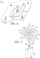
- FIG. 6 depicts an additional exemplary configuration for an attachment structure in accordance with aspects herein and is referenced generally by the numeral 600.
- FIG. 6 depicts a textile layer 610 to which a flexible, dimensionally stable frame 612 comprising a single aperture 614 defined by apertures edges 616 is applied.
- the dimensionally stable frame 612 may comprise an absorbent material, or an absorbent material may be applied to the frame 612.
- the aperture 614 may have diameter 618 sized to receive a larger device such as a larger TEM than those described in relation to, for instance, FIGs. 1-3 .
- the aperture diameter 618 may be between 3.0 to 8.0 cm, 4.0 to 7.0 cm, and/or between 3.0 to 5.0 cm, although diameters above and below these values are contemplated herein. Similar to the configurations described above, the diameter 618 of the aperture 614 may be intermediate between that of the base portion of the larger device and the flange portion of the larger device.
- FIGs. 16A and 16B respectively depict perspective views of a first and second opposing surface of a flexible textile 1600 adapted to receive one or more devices such as TEMs.
- FIG. 16A depicts a first surface 1610 of the textile 1600.
- Mating structures 1614 are shown as depressions or offsets in the negative z-direction from the first surface 1610 of the textile 1600.
- the mating structures 1614 are arranged in a pattern similar to that shown for the dimensionally stable frame 112 of FIG. 1 although other patterns are contemplated herein.
- FIG. 16B depicts a second surface 1612 of the textile 1600.
- the mating structures 1614 are shown as projections or offsets in the positive z-direction from the second surface 1612 of the textile 1600.
- the projections are complementary to the depressions shown in FIG. 16A .
- the depressions shown in FIG. 16A would be on the inner-facing surface of the apparel item, and the projections shown in FIG. 16B would be on the outer-facing surface of the apparel item.
- the number and pattern of the mating structures 1614 shown in FIGs. 16A and 16B are exemplary only, and it is contemplated herein that other patterns and numbers of mating structures 1614 may be used.
- the mating structures 1614 may be formed by manipulating a knit or weave pattern used to form the textile 1600.
- the mating structures 1614 may also be created by modifying the type of yarn used to create the textile 1600.
- a thermosetting yarn may be used such as a thermoplastic polyurethane yarn.
- a heat molding process may then be used to create the mating structures 1614.
- the hot side of the TEMs may be positioned within the depressions shown in FIG. 16A .
- the diameter of the TEMs may be slightly greater than the diameter of the mating structures 1614 thus ensuring that the TEMs are retained within the mating structures 1614 once inserted.
- an absorbent material such as a hydrogel or a SAP may be applied to the second surface 1612 of the textile 1600 adjacent to and/or positioned on the projections of the mating structures 1614.
- a flexible, dimensionally stable frame applied to a flexible textile as described herein enables devices, such as TEMs to be easily applied to the textile.
- the dimensionally stable frame may be easily integrated into an apparel item without significantly compromising the weight, pliability, and/or functional characteristics of the apparel item.
- an absorbent material to the dimensionally stable frame, or by forming the frame from a dimensionally stable absorbent material, such that moisture or sweat is concentrated and released in the areas around the hot side of the TEMs, the frame can play an important role in removing heat from the TEMs thereby improving their efficiency.
- thermoelectric module array that can be used as part of an apparel thermo-regulatory system for heating or cooling a wearer.
- An exemplary TEM array is shown in FIG. 7 and is referenced generally by the numeral 700.
- the TEM array 700 comprises device 710, device 712, device 714, device 716, device 718, device 720, and device 722.
- Each of the devices 712, 714, 716, 718, 720, and 722 may be physically and electrically connected to each other using an electrically insulating film 726 and a flexible electronic circuit 728.
- Exemplary films may comprise, for example, a polyimide film such as Kapton ® , a conductive polyester, a polyether ether ketone (PEEK) and the like.
- the film 726 may be configured to exhibit stretch characteristics (e.g., two-way stretch and/or four-way stretch).
- the film 726 besides being electrically insulating, may be elastomeric.
- the electronic circuit 728 may be formed on the film 726 using printing and/or photolithographic technology.
- the electronic circuit 728 may comprise flexible flat cables (FFCs) that are laminated between layers of the film 726.
- the film 726 and the electronic circuit 728 may be physically and electrically coupled to a power supply unit 730 such as a battery unit that is located approximately 4.0 to 8.0 cm from the device 716.
- the power supply unit 730 may be bi-polar such that it is capable of both heating and cooling.
- each of the devices 710, 712, 714, 716, 718, 720, and 722 may comprise a TEM. However, it is also contemplated herein that one or more of the devices 710, 712, 714, 716, 718, 720, or 722 may comprise a power supply unit such as a battery. It is further contemplated herein that one or more of the devices 710, 712, 714, 716, 718, 720, or 722 may comprise a sensor such as a temperature sensor used to detect the temperature of the wearer's skin and/or the temperature of the ambient air.
- one or more of the devices 710, 712, 714, 716, 718, 720, or 722 may comprise a microprocessor.
- the temperature sensor, microprocessor, and/or power supply unit may be integrated within a TEM.
- the microprocessor may be programmed, for example, to change the polarity of the TEMs such that the cold side of the TEM becomes the hot side and vice versa.
- the microprocessor may also be programmed to, for instance, cycle the TEM array 700 from an on state to an off state and vice versa based on a duty cycle, based on an input received from a user, and/or based on a temperature detected by the temperature sensor.
- the microprocessor may additionally be programmed to modulate the amount of current and/or voltage supplied to the TEM array 700 to achieve a predefined temperature or temperature range for the hot side or the cold side of the TEM.
- the microprocessor may be adapted to communicate with a mobile application via, for instance, Bluetooth ® , near-field communication, or other wireless technologies. As such, the microprocessor may be programmed via the mobile application. As well, in an exemplary aspect, the microprocessor may be adapted to communicate with TEMs in the array 700 using Bluetooth ® , near-field communication, or other wireless technologies, although wired communication is also contemplated herein.
- the microprocessor may be programmed to maintain the cool side of each TEM between 10 °C and °20 C when the TEMs are used for cooling. When used for heating, the microprocessor may be programmed to maintain the hot side of each TEM between 30 °C and 45 °C in exemplary aspects. Further, the microprocessor may be programmed to alter the polarity of the TEMs in order to cycle one side of the TEM from a cold state to a hot state to promote recovery from, for example, exercise. It is contemplated herein that the microprocessor may be programmed to selectively activate one or more TEMs in the array. For example, a first and second TEM may be activated but not a third and fourth TEM. Other selective activation scenarios are contemplated herein.
- An additional programming aspect contemplated herein is the ability to program maximum and/or minimum temperature limits that, when triggered cause the microprocessor to turn off the TEM array 700 entirely or to turn off one or more TEMs in the array 700 to promote wearer safety.
- a maximum temperature of 50 °C may be set for the hot side of the TEM (i.e., the side exposed to the ambient air) to avoid overheating the TEM.
- a maximum temperature of 40 °C may be set for the cold side of the TEM to avoid burning the wearer's skin.
- a minimum temperature of, for instance, 5 °C may be set for the cold side of the TEM to avoid freezing the wearer's skin.
- Another safety measure contemplated herein is to limit the maximum voltage of each TEM to less than 12 V to prevent inadvertent electrical shock.
- each TEM array may be used on an apparel item to provide heating and/or cooling zones to different areas of the apparel item.
- each TEM array may comprise its own microprocessor and/or sensor.
- each array may be independently adjustable to provide customized heating or cooling to different areas of the apparel item.
- each device 710, 712, 714, 716, 718, 720, and 722 may comprise, for instance, a cold side plate, a thermoelectric chip (TEC), an insulating ring, and a hot side plate.
- TEC thermoelectric chip
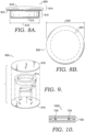
- FIG. 9 depicts an exploded view of an exemplary TEM 900.
- the TEM 900 may comprise a cold side plate 910 formed from, for instance, anodized aluminum, a sealed TEC 912, an insulating ring 914 formed from, for instance, a closed cell foam material, and a hot side plate 916 formed from, for example, anodized aluminum.
- an anodized aluminum on the cold side plate 910 and the hot side plate 916 of the TEM 900 acts as a secondary electrical insulation barrier between the TEC 912 and a wearer's body.
- the TEC 912 is coated with an electrically insulating material to prevent direct electrical contact with other elements of the TEM 900.
- the electrically insulating material encasing the TEC 912 also serves as a moisture barrier.
- the top and bottom plates of the TEC 912 may comprise an electrically insulating alumina ceramic which helps to insulate the top and bottom plates of the TEC 912 from other elements in the TEC 912.
- any lead wires that connect to the TEM 900 may also be insulated.
- the insulating ring 914 not only provides support from mechanical impact but helps to insulate the hot side plate 916 from the cold side plate 910. It also helps to prevent moisture from entering the TEM 900.
- the different components described above may be assembled by seating the TEC 912 on the cold side plate 910 and bonding the hot side plate 916 to the cold side plate 910 via the insulating ring 914 using, for instance, an epoxy. Once assembled, the TEM 900 may be sealed to further reduce the risk of moisture entering the TEM 900.
- FIG. 8A depicts a side view of an exemplary device 800 such as a TEM
- FIG. 8B depicts a top view of the device 800 in accordance with aspects herein.
- the device 800 comprises a cylindrical base portion 810 having a first planar surface 812, and a cylindrical flange portion 814 that is contiguous with and radially extends from the cylindrical base portion 810.
- the flange portion 814 comprises a generally planar second surface 816 opposite the first surface 812.
- the first surface 812 comprises the cold side of the device 800 when configured as a TEM
- the second surface 816 comprises the hot side of the device 800 when configured as a TEM.
- the cylindrical base portion 810 may have a diameter 818 between 21.0 mm and 23.0 mm, 22.0 mm and 23.0 mm, 22.4 mm and 22.8 mm, and/or between 22.5 mm and 22.7 mm, although diameters above and below these values are contemplated herein.
- the flange portion 814 may have a diameter 820 between 27.0 mm and 29.0 mm, 28.0 mm and 29.0 mm, 28.4 mm and 28.8 mm, and/or between 28.5 mm and 28.7 mm, although diameters above and below these values are contemplated herein.
- the diameter 820 of the flange portion 814 may be approximately 6.0 mm greater than the diameter 818 of the base portion 810.
- the flange portion 814 may radially extend from the cylindrical base portion 810 by approximately 3.0 mm as indicated by reference numeral 824 in FIG. 8B to form a lip 822 shown in FIG. 8A .
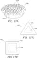
- the second surface 816 of the flange portion 814 may formed to have a series of protuberances 1710 and grooves 1712 to increase its surface area.
- the surface area of the second surface 816 i.e., the hot side of the TEM
- the area through which heat may be dissipated from the TEM may be increased further facilitating the efficiency of the TEM.
- FIG. 17B illustrates a top view of a TEM 1720 which illustrates a triangular shape for the TEM 1720.
- the flange portion 1722 of the TEM 1720 has a triangular shape as well as the base portion 1724 of the TEM 1720 (shown by the dashed line).
- the flange portion 1722 may extend past the base portion 1724 to form a lip useable for securing the TEM 1720 within a similarly shaped aperture of a dimensionally stable frame.
- FIG. 17B illustrates a top view of a TEM 1720 which illustrates a triangular shape for the TEM 1720.
- the flange portion 1722 of the TEM 1720 has a triangular shape as well as the base portion 1724 of the TEM 1720 (shown by the dashed line).
- the flange portion 1722 may extend past the base portion 1724 to form a lip useable for securing the TEM 1720 within a similarly shaped aperture of a dimensional
- FIG. 17C illustrates a top view of a TEM 1740 which illustrates a square shape for the TEM 1740. More specifically, the flange portion 1742 of the TEM 1740 has a square shape as well as the base portion 1744 of the TEM 1740 (shown by the dashed line). Similar to the TEM 1720 described above, the flange portion 1742 may extend past the base portion 1744 to form a lip useable for securing the TEM 1740 within a similarly shaped aperture of a dimensionally stable frame. Other shapes are contemplated herein for the TEMs.
- the shape of a TEM may be chosen to preserve the flexibility, drapability, and/or pliability of an apparel item which incorporates the TEM as part of a thermo-regulatory system. For example, by configuring the TEMs to have a triangular shape, a greater number of flexion points between adjacent TEMs may be achieved as compared to, for example, utilizing square-shaped TEMs. This in turn, may help to maintain the pliability of the apparel item.
- the device arrays described herein may assume a number of different patterns or configurations.
- the devices 710, 712, 714, 716, 718, and 720 are radially arranged around the device 722, where the device 722 is located centrally between the other devices 710, 712, 714, 716, 718, and 720 to form a spoke-and-hub pattern.
- the use of between, for instance, five to seven TEMs arranged in a radial pattern provides for an adequate cooling or heating area when incorporated into an apparel item without significantly compromising the flexibility, drapability, and/or functional characteristics of the apparel item.
- adjacent devices in the array 700 may have a center-to-center offset 724 of between 2.5 cm to 4.0 cm, 3.0 cm to 3.8 cm, and/or between 3.4 cm and 3.6 cm although the center-to-center offset 724 may be greater than or lesser than these values.
- FIG. 18A depicts an array 1800 comprising devices 1810, 1812, 1814, and 1816 arranged in a linear pattern in accordance with aspects herein.
- the devices 1810, 1812, 1814, and 1816 may be physically and electrically coupled using an electrically insulating film 1818.
- FIG. 18B depicts an array 1850 comprising devices 1852, 1854, 1856, and 1858 arranged in a staggered linear pattern in accordance with aspects herein.
- the devices 1852, 1854, 1856, and 1858 may be physically and electrically coupled using an electrically insulating film 1860.
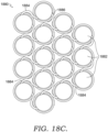
- FIG. 18C depicts an array 1880 of devices 1882 configured in an auxetic pattern in accordance with aspects herein.
- the devices 1882 are located adjacent to each other and are interconnected by a series of spokes 1884.
- each spoke 1884 may be hingedly attached to a respective device 1882 (as indicated by reference numeral 1886) such that the device 1882 can rotate or pivot in relation to the attachment point of the spoke 1884.
- the rotation or pivoting of the device 1882 relative to the attachment point of the spoke 1884 occurs in the same plane as the spoke 1884.
- each device 1882 may be connected to up to three to six adjacent devices 1882.
- the spokes 1884 may comprise an electrically insulating material such as the film 726 of FIG. 7 , having or containing a flexible electronic circuit, such as the circuit 728 of FIG. 7 .
- the spokes 1884 may also act to electrically interconnect the devices 1882.
- the devices 1882 may be electrically connected through other means besides the spokes 1884. Any and all aspects, and any variation thereof, are contemplated as being within aspects herein.
- the use of the hingedly attached spokes 1884 enables the array 1880 to assume an auxetic pattern (i.e., a pattern or structure that exhibits a negative Possion's ratio that causes the pattern to become thicker in a direction perpendicular to an applied force).
- an auxetic pattern i.e., a pattern or structure that exhibits a negative Possion's ratio that causes the pattern to become thicker in a direction perpendicular to an applied force.
- a force is applied to the array 1880 as indicated by the arrows 1888.
- the array 1880 becomes wider in a direction perpendicular to the applied force 1888 due to the devices 1882 pivoting relative to the spokes 1884.
- the use of an array exhibiting an auxetic pattern, such as the array 1880 may help to increase the flexibility and/or drapability of the array 1880 such that it more easily conforms to a wearer's surface morphology when incorporated into an apparel item.
- Selection of a particular device array pattern may be based on the location of the array on an apparel item. For example, and as described in greater detail below, a linear or staggered array of devices may be sufficient for areas of the apparel item that are positioned adjacent to relatively planar body surfaces or areas of the body that do not generate large quantities of heat, or for those areas of the apparel item that undergo little movement such as, for example, the sleeve portions of a shirt.
- the spoke-and-hub pattern or the auxetic pattern may be used for those areas of the apparel item that are positioned adjacent to more convex or concave body surfaces (shoulders, buttocks, upper chest, and the like) or areas of the body that produce higher quantities of heat, or for those areas of the apparel item that undergo significant flexion/extension during activity. These are just examples, and the positioning of a particular array pattern may differ from those described.
- FIG. 10 depicts a cross-sectional view, referenced generally by the numeral 1000, of the film 726 and the electronic circuit 728 taken along cut line 10-10 of FIG. 7 in accordance with aspects herein.
- the film 726 encloses and seals the electronic circuit 728 in order to electrically insulate the circuit 728.
- the film 726 may be optionally positioned between additional film layers.
- the film layers may comprise, for example, thermoplastic polyurethane, polyurethane, silicone, rubber, plastic, and the like.
- the additional film layers may be used to as a secondary level of insulation to prevent moisture from contacting the electronic circuit 728.
- the film 726 and the additional film layers (if used) may be adhered together through a heat bonding process to seal the resulting structure.
- the TEM array described herein provides for a flexible structure that can be incorporated into an apparel item to provide programmable heating, cooling, or recovery features.
- the array may be sized and configured to enable an adequately sized heating or cooling area while still maintaining the flexibility, drapability, and functional features of the apparel item.
- the TEM array comprises safety features designed to reduce the risk of electrical shock, burning, and/or freezing.
- thermo-regulatory system designed to actively heat or cool a wearer or provide recovery features to the wearer when the apparel item is worn.
- the thermo-regulatory system may comprise, for instance, an apparel item and one or more TEM arrays positioned on the apparel item at predetermined locations and held in place through use of one or more dimensionally stable frames.
- FIG. 11 illustrates an exploded view of a portion of an apparel thermo-regulatory system 1100 in accordance with aspects herein.
- the thermo-regulatory system comprises: 1) a TEM array 1110 having TEMs 1111; 2) a flexible textile 1112; 3) a perforated dimensionally stable frame 1114 having apertures 1115, a first surface 1122, and a second surface 1124; and 4) an absorbent material 1116 having optional apertures 1117.
- Aspects of the TEM array 1110, the dimensionally stable frame 1114, and the absorbent material 1116 were discussed above.
- the spoke-and-hub pattern is shown with respect to the TEM array 1110, it is contemplated herein that other array patterns may be used as described herein.
- the shape of the TEMs 1111 is shown as being circular, it is contemplated herein that other shapes for the TEMs 1111 may be used (e.g., triangular, square, and the like). Any and all aspects, and any variation thereof, are contemplated as being within aspects herein.
- the textile 1112 may comprise a wicking fabric adapted to transport moisture from a first surface 1118 of the textile 1112 to a second surface 1120 of the textile 1112.
- the second surface 1120 of the textile 1112 would comprise an outer-facing surface of an apparel item and the first surface 1118 of the textile 1112 would comprise an inner-facing surface of the apparel item.
- the fabric of the textile 1112 may be selected to have a high heat resistance so that it is able to withstand direct contact temperatures of at least 50 °C without deforming and/or without appreciably warming.
- the first surface 1122 of the dimensionally stable frame 1114 would be affixed (either releasably or permanently) to the second surface 1120 of the textile 1112, and the absorbent material 1116 would be applied to the second surface 1124 of the dimensionally stable frame 1114.
- the hot side of the TEMs 1111 in the TEM array 1110 would be positioned adj acent to the first surface 1118 of the textile 1112 such that the TEMs 1111 axially align with the apertures 1115 of the dimensionally stable frame 1114 and/or the apertures 1117 of the absorbent material 1116.
- an upward pressure to, for instance, the cold side of the TEMs 1111 causes the TEMs 1111 to "snap" into the apertures 1115 of the dimensionally stable frame 1114 and/or the apertures 1117 of the absorbent material 1116 thus releasably securing the TEM array 1110 to the textile 1112 while maintaining the structural integrity of the textile 1112.
- the TEM array 1110 may be removed from the textile 1112 by exerting a downward pressure on the hot side of the TEMs 1111 causing them to disengage from the apertures 1115.
- FIG. 11 is exemplary only and other configurations are contemplated herein.
- the configuration shown in FIG. 3 where the dimensionally stable frame is formed of an absorbent material is contemplated herein. Any and all aspects, and any variation thereof, are contemplated as being within aspects herein.
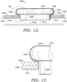
- FIG. 12 depicts a TEM 1210 having a cold side plate 1212 and a hot side plate 1214 where the cold side plate 1212 is adapted to be positioned adjacent a skin surface 1234 of a wearer.
- a space is intentionally shown between the cold side plate 1212 and the skin surface 1234 to better illustrate aspects of the configuration. In reality the space between the cold side plate 1212 and the skin surface 1234 would be non-existent or negligible.
- FIG. 12 further depicts a flexible textile 1216 having a first surface 1218 and a second opposite surface 1220; a dimensionally stable frame 1222 having a first surface 1224, a second opposite surface 1226, and an aperture defined by aperture edges 1232; and an absorbent material 1228 applied to the second surface 1226 of the dimensionally stable frame 1222.
- the hot side plate 1214 of the TEM 1210 is positioned adjacent to the first surface 1218 of the textile 1216 (away from the skin surface 1234), and the first surface 1224 of the dimensionally stable frame 1222 is positioned adjacent to the second surface 1220 of the textile 1216.
- the cold side plate 1212 may actually comprise a hot side depending on the polarity of the TEM 1210, and, similarly, the hot side plate 1214 may comprise a cold side. Any and all aspects, and any variation thereof, are contemplated as being within aspects herein.
- the TEM 1210 has the structure depicted for the device 800 shown in FIGs. 8A and 8B .
- the TEM 1210 has a flange portion comprising the hot side plate 1214, where the flange portion radially extends from a cylindrical base portion comprising the cold side plate 1212 to form a lip 1230 that extends circumferentially around the cylindrical base portion of the TEM 1210.
- the diameter of the aperture of the dimensionally stable frame 1222 is intermediate between the diameter of the cylindrical base portion and the diameter of the flange portion of the TEM 1210.
- FIG. 13 is a magnified view of FIG. 12 taken at the indicated area and illustrating how the lip 1230 of the TEM 1210 helps to secure the TEM 1210 within the dimensionally stable frame 1222.
- the lip 1230 rests on the second surface 1226 of the dimensionally stable frame 1222.
- a downward pressure may be applied to the hot side plate 1214 to disengage the TEM 1210.
- the textile 1216 covers and/or is positioned adjacent to the hot side plate 1214 of the TEM 1210.
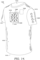
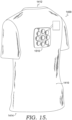
- FIGs. 14 and 15 front and back perspective views respectively of an apparel item 1400 having a thermo-regulatory system are depicted in accordance with aspects herein. Although shown in the form of a shirt, it is contemplated herein that the apparel item 1400 may be in the form of a pant, a short, a compression sleeve for an arm or a leg, a headband, a shoe, and the like.
- the apparel item 1400 comprises at least a torso portion 1410 (e.g., a front and back portion) adapted to cover a torso area of a wearer when the apparel item 1400 is in an as-worn configuration.
- the torso portion 1410 defines at least a neck opening 1412 and a waist opening 1414.
- the apparel item 1400 may also optionally comprise sleeve portions 1411 and 1413 adapted to cover the arms of the wearer when the apparel item 1400 is worn.
- the apparel item 1400 may comprise a form-fitting apparel item formed of a material exhibiting a moderate to high degree of elasticity such that the apparel item 1400 generally conforms to the body surfaces of the wearer when worn.
- thermo-regulatory system 1416 such as the thermo-regulatory system shown in FIG. 11 , is shown positioned on a front aspect of the torso portion 1410 (seen in FIG. 14 ) proximate to the neck opening 1412, and a thermo-regulatory system 1510 is shown positioned on a back aspect of the torso portion 1410 (seen in FIG. 15 ) proximate to the neck opening 1412.
- proximate means within 5 to 25 cm of the neck opening 1412.
- a thermo-regulatory system 1426 is shown positioned on the sleeve portion 1413 (a similar thermo-regulatory system may also be positioned on the sleeve portion 1411).
- thermo-regulatory systems 1416 and 1510 are positioned generally along a vertical midline of the front and back of the apparel item 1400.
- the areas in which the thermo-regulatory systems 1416 and 1510 are positioned generally correspond to high heat and/or sweat producing areas of a human body as based on, for instance, heat maps and sweat maps.
- the area in which the thermo-regulatory system 1426 is positioned may generally correspond to a medium to low heat producing area.
- each thermo-regulatory system 1416, 1510, and 1426 comprises a cooling (or a heating or a recovery) zone on the apparel item 1400.
- thermo-regulatory system 1416 may comprise a dimensionally stable frame 1418 affixed to the apparel item 1400 and into which TEMs 1420 are mated.
- the film and the electronic circuit 1422 used to physically and electrically couple the TEMs 1420 are shown by dashed lines to indicate they are located on the inner-facing surface of the apparel item 1400.
- a power supply unit 1424 is also shown as being physically and electrically coupled to the TEMs 1420 via the film and electronic circuit 1422.
- the power supply unit 1424 is also shown by dashed lines to indicate that it may be located on the inner-facing surface of the apparel item.
- the power supply unit 1424 may be positioned on the outer-facing surface of the apparel item 1400 in some aspects.
- the power supply unit 1424 may be secured to the apparel item 1400 using, for instance, a pocket, a releasable fastener system such as a loop-and-hook fastener, snaps, buttons, and the like.
- the power supply unit 1424 may be configured as one of the devices in the TEM array as described above.
- the power supply unit 1424 may not comprise a separate unit such as that shown in FIG. 14 . Any and all aspects, and any variation thereof, are contemplated as being within aspects herein.
- thermo-regulatory system 1416 is equally applicable to the thermo-regulatory system 1510 and the thermo-regulatory system 1426. Additionally, it is contemplated herein that the apparel item 1400 may comprise additional thermo-regulatory systems positioned on the apparel item 1400 in locations corresponding to high to medium heat and/or sweat producing areas. In one example, the apparel item may comprise between 1 and 15 thermo-regulatory systems to provide a corresponding number of heating or cooling zones.
- a wearer may independently program the thermo-regulatory system 1416, the thermo-regulatory system 1426, and the thermo-regulatory system 1510 using, for instance, a mobile application. For instance, the wearer may program a temperature set point for the cold side of the TEMs and/or the hot side of the TEMs. The wearer may also program a cycling time for each thermo-regulatory system 1416, 1426, and 1510 ( i.e ., a time period in which the thermo-regulatory system 1416, 1426, and/or 1516 is in an on state and/or an off state).
- thermo-regulatory systems 1416, 1426, and/or 1510 may help to prevent habituation by the wearer.
- the wearer may additionally program a recovery cycle that causes the surface of the TEMs in contact with the wearer's skin surface to alternate between a hot state and a cold state. Any and all aspects, and any variation thereof, are contemplated as being within aspects herein.
- the wearer would don the apparel item 1400 and begin exercising or begin his or her job duties when used by, for example, firefighters or military personnel.
- the wearer may don the apparel item 1400 subsequent to exercising in order to cool down and or to promote recovery.
- the sweat may move from an inner-facing surface of the apparel item 1400 to the outer-facing surface of the apparel item 1400 due to the wicking properties of the textile forming the apparel item 1400.
- the sweat may then accumulate in the absorbent material deposited on the dimensionally stable frame of the thermo-regulatory systems 1416, 1426, and/or 1510. This process may be helped by perforating the dimensionally stable frame such that the sweat can move from the textile forming the apparel item 1400 to the absorbent material.
- the accumulation of sweat in the absorbent material is facilitated by positioning the thermo-regulatory systems 1416 and 1510 on the apparel item 1400 in locations positioned adjacent to high sweat-producing areas of the wearer.
- the absorbent material surrounds and/or is positioned adjacent to the hot side of the TEMs, release of the sweat by the absorbent material and its subsequent evaporation from the hot side of the TEMs helps to remove heat from the TEMs. This, in turn, helps the TEMs to operate more efficiently. For example, by dissipating heat from the hot side of the TEMs, a greater temperature differential can be maintained between the cold side and the hot side of the TEMs. This, in turn, reduces the amount of power needed to run the TEMs.
- the use of the wearer's own sweat to dissipate heat from the hot side of the TEMs may be augmented by providing an external liquid source to the hot side of the TEMs.
- water may be sprayed or applied to the apparel item 1400 in areas where the thermo-regulatory systems 1416, 1426, and 1510 are located. Evaporation of the water may further help to dissipate heat from the hot side of the TEMs.
- removal of heat from the hot side of the TEMs via evaporation may be further enhanced by air movement over the thermo-regulatory systems 1416, 1426, and/or 1510 either through intrinsic wearer movement ( e.g ., running) or by an external wind source such as fans.
- thermo-regulatory systems 1416, 1426, and 1510 may be utilized.
- wicking threads or yarns may be integrated into the apparel item 1400 such that a first end of the wicking thread is positioned at a location disparate from the thermo-regulatory systems 1416, 1426, and 1510 and a second end of the wicking thread is positioned adjacent the TEMs and/or adjacent to the absorbent material.
- a first end of the wicking threads or yarns may be positioned at areas of the apparel item proximate to the waist opening 1414.
- sweat generated at a location on the apparel item that is disparate from the thermo-regulatory systems 1416, 1426, and/or 1510 may be transported to the systems 1416, 1426, and/or 1510 using the wicking threads.
- some or all of the apparel item 1400 may be formed from a hydrophobic material and hydrophilic channels may be created on the apparel item 1400 via for instance, a process that deposits a hydrophilic material on the apparel item 1400, the use of hydrophilic fabrics, and the like.
- the channels may be used to transport sweat generated at a location on the apparel item 1400 that is disparate from the thermo-regulatory systems 1416, 1426, and/or 1510 to the systems 1416, 1426, and/or 1510.
- a hydrophobic treatment may be applied to the apparel item 1400 in such a way as to force moisture and/or sweat to travel along hydrophilic channels formed by, for instance, a hydrogel or SAP applied to the apparel item 1400 and/or by forming the apparel item 1400 from a moisture wicking fabric. Any and all aspects, and any variation thereof, are contemplated as being within aspects herein.
- thermo-regulatory systems 1416, 1426, and 1510 may also be used to heat the wearer.
- the polarity of the TEMs may be reversed such that the cold side of the TEMs becomes the hot side and the hot side of the TEMs becomes the cold side.
- the hot side of the TEMs is positioned to be adjacent to a skin surface of a wearer when the apparel item 1400 is worn.
- the wearer can program the hot side of the TEMs to a desired temperature such as between, for example, 30 to 40 °C, set a cycle time, and the like.
- the heat can be dissipated to the wearer's skin surface helping to warm the wearer.
- thermo-regulatory systems 1416, 1426, and 1510 may also be used to help the wearer recover from athletic activities.
- the TEMs in the thermo-regulatory systems 1416, 1426, and 1510 may be programmed to cycle from a hot state to a cold state. More particularly, the polarity of the TEMs may be cyclically changed such that the cold side of the TEM becomes the hot side and then cycles back to the cold side according to a programmed schedule.
- thermo-regulatory systems may also be incorporated into other apparel items such as pants.
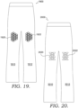
- FIG. 19 depicts a front view of a pair of pants 1900 having a thermo-regulatory system 1920 positioned at an anterior, upper portion of a first leg portion 1910 of the pant 1900 and a thermo-regulatory system 1922 positioned at an anterior, upper portion of a second leg portion 1912 of the pant 1900.
- These locations may correspond to the quadriceps muscle groups of a wearer when the apparel item 1900 is worn. In exemplary aspects, these locations may correspond to high heat producing areas of a wearer and, as well, may correspond to muscle groups that may benefit from the recovery features associated with the thermo-regulatory systems described herein ( i.e ., alternating heating and cooling features).
- thermo-regulatory systems 1920 and 1922 are shown as having an auxetic pattern as described in relation to FIGs. 18C-18D .
- spokes between adjacent TEMs are shown as being on the outer-facing surface of the apparel item 1900, it is contemplated herein that the TEMs with their associated spokes would be positioned adjacent the inner-facing surface of the apparel item 1900.
- the depiction shown in FIG. 19 is for illustrative purposes only.
- thermo-regulatory systems 1920 and 1922 Because the thigh area of a wearer is a generally convex, tubular-shaped area, using an auxetic pattern for the thermo-regulatory systems 1920 and 1922 enables the systems 1920 and 1922 to "wrap around" the thigh area of a wearer in order to maintain close contact with the wearer's skin surface and allows the thermo-regulatory systems 1920 and 1922 to flex and extend with wearer movement.
- thermo-regulatory systems may be used in association with the pants 1900.
- thermo-regulatory systems may be located on the back of the pant, along the shin/calf areas of the pant, across the buttocks area of the pants, and the like.
- the systems may assume a variety of patterns such as the spoke-and-hub, linear, and staggered patterns described herein.
- shape of the TEMs may be different from that shown ( e.g ., triangular, square, rectangle, and the like). Any and all aspects, and any variation thereof, are contemplated as being within aspects herein.
- FIG. 20 illustrates a front view of a pant 2000 having at least a first leg portion 2010 and a second leg portion 2012.
- a thermo-regulatory system 2020 having triangular-shaped TEMs is located at an upper part of the first leg portion 2010, and a thermo-regulatory system 2022 having triangular-shaped TEMs is located at an upper part of the second leg portion 2012. These locations are exemplary only.
- the triangular-shaped TEMs in the thermo-regulatory systems 2020 and 2022 are arranged in a tessellation-type pattern such that there are minimal gaps between adjacent TEMs.
- thermo-regulatory systems 2020 and 2022 may act as flexion/extension areas allowing the systems 2020 and 2022 to conform to a wearer's surface morphology and/or to flex and extend with wearer movement. This both improves wearer comfort and increases the area of contact of the systems 2020 and 2022 with the wearer's skin surface thereby providing more effective heating and cooling.
- the TEMs may comprise different shapes suitable to form tessellation-type patterns as described herein.
- the apparel thermo-regulatory system described herein enables an effective heating/cooling mechanism in the form of TEM arrays to be integrated into an apparel item without significantly comprising the weight and/or integrity of the apparel item as well as the different functional characteristics of the apparel item.
Landscapes
- Engineering & Computer Science (AREA)
- Health & Medical Sciences (AREA)
- Textile Engineering (AREA)
- General Health & Medical Sciences (AREA)
- Life Sciences & Earth Sciences (AREA)
- Physics & Mathematics (AREA)
- Physical Education & Sports Medicine (AREA)
- Environmental & Geological Engineering (AREA)
- Heart & Thoracic Surgery (AREA)
- Biophysics (AREA)
- Thermal Sciences (AREA)
- General Engineering & Computer Science (AREA)
- Mechanical Engineering (AREA)
- Molecular Biology (AREA)
- Physiology (AREA)
- Medical Informatics (AREA)
- Pathology (AREA)
- Surgery (AREA)
- Animal Behavior & Ethology (AREA)
- Public Health (AREA)
- Veterinary Medicine (AREA)
- Cardiology (AREA)
- Biomedical Technology (AREA)
- Pulmonology (AREA)
- Gerontology & Geriatric Medicine (AREA)
- Business, Economics & Management (AREA)
- Emergency Management (AREA)
- General Physics & Mathematics (AREA)
- Chemical & Material Sciences (AREA)
- Combustion & Propulsion (AREA)
- Professional, Industrial, Or Sporting Protective Garments (AREA)
- Laminated Bodies (AREA)
- Outerwear In General, And Traditional Japanese Garments (AREA)
Applications Claiming Priority (5)
| Application Number | Priority Date | Filing Date | Title |
|---|---|---|---|
| US201662410453P | 2016-10-20 | 2016-10-20 | |
| US15/786,879 US10842205B2 (en) | 2016-10-20 | 2017-10-18 | Apparel thermo-regulatory system |
| EP23182945.8A EP4242553A3 (de) | 2016-10-20 | 2017-10-20 | Befestigungsstruktur zur befestigung mindestens einer vorrichtung an einem bekleidungsstück |
| PCT/US2017/057659 WO2018075929A1 (en) | 2016-10-20 | 2017-10-20 | Attachment structure for attaching at least one device to an apparel item |
| EP17794539.1A EP3503751B1 (de) | 2016-10-20 | 2017-10-20 | Befestigungsstruktur zur befestigung mindestens einer vorrichtung an einem bekleidungsstück |
Related Parent Applications (2)
| Application Number | Title | Priority Date | Filing Date |
|---|---|---|---|
| EP23182945.8A Division EP4242553A3 (de) | 2016-10-20 | 2017-10-20 | Befestigungsstruktur zur befestigung mindestens einer vorrichtung an einem bekleidungsstück |
| EP17794539.1A Division EP3503751B1 (de) | 2016-10-20 | 2017-10-20 | Befestigungsstruktur zur befestigung mindestens einer vorrichtung an einem bekleidungsstück |
Publications (2)
| Publication Number | Publication Date |
|---|---|
| EP4411684A2 true EP4411684A2 (de) | 2024-08-07 |
| EP4411684A3 EP4411684A3 (de) | 2024-10-16 |
Family
ID=61971370
Family Applications (3)
| Application Number | Title | Priority Date | Filing Date |
|---|---|---|---|
| EP17794539.1A Active EP3503751B1 (de) | 2016-10-20 | 2017-10-20 | Befestigungsstruktur zur befestigung mindestens einer vorrichtung an einem bekleidungsstück |
| EP24182161.0A Pending EP4411684A3 (de) | 2016-10-20 | 2017-10-20 | Bekleidungswärmeregulierungssystem |
| EP23182945.8A Pending EP4242553A3 (de) | 2016-10-20 | 2017-10-20 | Befestigungsstruktur zur befestigung mindestens einer vorrichtung an einem bekleidungsstück |
Family Applications Before (1)
| Application Number | Title | Priority Date | Filing Date |
|---|---|---|---|
| EP17794539.1A Active EP3503751B1 (de) | 2016-10-20 | 2017-10-20 | Befestigungsstruktur zur befestigung mindestens einer vorrichtung an einem bekleidungsstück |
Family Applications After (1)
| Application Number | Title | Priority Date | Filing Date |
|---|---|---|---|
| EP23182945.8A Pending EP4242553A3 (de) | 2016-10-20 | 2017-10-20 | Befestigungsstruktur zur befestigung mindestens einer vorrichtung an einem bekleidungsstück |
Country Status (4)
| Country | Link |
|---|---|
| US (3) | US10842205B2 (de) |
| EP (3) | EP3503751B1 (de) |
| CN (3) | CN109788810B (de) |
| WO (1) | WO2018075929A1 (de) |
Families Citing this family (32)
| Publication number | Priority date | Publication date | Assignee | Title |
|---|---|---|---|---|
| CA2797980C (en) | 2010-05-12 | 2015-08-18 | Irhythm Technologies, Inc. | Device features and design elements for long-term adhesion |
| JP6198849B2 (ja) | 2013-01-24 | 2017-09-20 | アイリズム・テクノロジーズ・インコーポレイテッドiRhythm Technologies,Inc. | 生理学的信号をモニターする電子装置、及び該電子装置の部分を除去交換する方法 |
| US20160120434A1 (en) | 2014-10-31 | 2016-05-05 | Irhythm Technologies, Inc. | Wireless physiological monitoring device and systems |
| US10842205B2 (en) | 2016-10-20 | 2020-11-24 | Nike, Inc. | Apparel thermo-regulatory system |
| US20190350752A1 (en) * | 2016-11-29 | 2019-11-21 | RecoverX, Inc. | Wearable temperature therapy system and method |
| US10631580B2 (en) * | 2017-01-17 | 2020-04-28 | Nike, Inc. | Waistband with support panel |
| US11896393B1 (en) * | 2017-03-01 | 2024-02-13 | CB Innovations, LLC | Wearable diagnostic electrocardiogram garment |
| JP7391381B2 (ja) * | 2017-10-12 | 2023-12-05 | エンブル・ラブス・インコーポレイテッド | 触覚アクチュエータ及びそれらの使用の方法 |
| EP3732737A4 (de) * | 2017-12-27 | 2022-01-19 | 3M Innovative Properties Company | Flexible thermoelektrische vorrichtung |
| US10842250B2 (en) * | 2018-01-22 | 2020-11-24 | Dominic DiPierro | Clothing integrated tab system |
| US10736408B2 (en) * | 2018-03-09 | 2020-08-11 | Jean-Pierre Paillasson | Audio cable holder |
| US11923472B2 (en) * | 2018-11-05 | 2024-03-05 | The United States Of America As Represented By The Secretary Of The Army | Deformable array of semiconductor devices |
| EP3666179A1 (de) * | 2018-12-11 | 2020-06-17 | Koninklijke Philips N.V. | Kernkörpertemperatursensorsystem auf basis von flussmessung |
| IL268998B2 (en) * | 2019-08-29 | 2023-02-01 | Ofer Nidam | Inflatable item |
| US20210059325A1 (en) * | 2019-09-03 | 2021-03-04 | Purdue Research Foundation | Outerwear Having Active Thermal Exchange |
| JP7480456B2 (ja) * | 2020-01-15 | 2024-05-10 | 株式会社Zetalpha Device Japan | 空調ユニット及び空調モジュール |
| JP7406001B2 (ja) | 2020-02-12 | 2023-12-26 | アイリズム・テクノロジーズ・インコーポレイテッド | 患者の生理学的特徴を推論するための、非侵襲的な心臓モニタ、および記録された心臓データの使用方法 |
| JP2022010752A (ja) * | 2020-06-29 | 2022-01-17 | 山真製鋸株式会社 | 空調服 |
| WO2022032117A1 (en) | 2020-08-06 | 2022-02-10 | Irhythm Technologies, Inc. | Adhesive physiological monitoring device |
| JP7796108B2 (ja) | 2020-08-06 | 2026-01-08 | アイリズム・テクノロジーズ・インコーポレイテッド | 生理学的モニタリング装置の電気部品 |
| US11602454B1 (en) | 2020-10-13 | 2023-03-14 | Hyper Ice, Inc. | Temperature modulation assembly and a multi-layer retention mechanism for a temperature therapy device |
| GB2601180B (en) * | 2020-11-23 | 2025-07-23 | Cryogenx Ltd | A wearable cooling apparatus for on-site treatment of heat illness |
| US11641951B2 (en) * | 2020-12-16 | 2023-05-09 | Comfort Innovations Llc | Temperature-controlled cradle |
| WO2022174231A1 (en) * | 2021-02-09 | 2022-08-18 | Marc Richelsoph | Adaptive temperature control system for garments and methods for controlling temperature of garments |
| US12167756B2 (en) * | 2021-03-09 | 2024-12-17 | World Emblem International, Inc. | Utilization method and tag with embedded RF-enabled chip |
| US12465781B2 (en) | 2021-06-11 | 2025-11-11 | Joon Bu Park | Negative Poisson's ratio materials for thermal and radiation therapy seeds |
| GB2623669A (en) * | 2021-07-22 | 2024-04-24 | Kota Kiran | Flexible thermoelectric device |
| USD1063079S1 (en) | 2021-08-06 | 2025-02-18 | Irhythm Technologies, Inc. | Physiological monitoring device |
| US11771587B1 (en) * | 2021-08-30 | 2023-10-03 | Snapbac, Llc | Portable rechargeable therapy pods |
| CN113584067B (zh) | 2021-09-29 | 2022-01-18 | 中国海洋大学 | 基于群体感应的自诱导调控系统及其应用 |
| US12569014B2 (en) * | 2022-04-29 | 2026-03-10 | Michael Allen Buckman | Portable cooling device |
| US20240358543A1 (en) * | 2023-04-28 | 2024-10-31 | University Of North Texas | Peltier-integrated therapeutic wrap |
Family Cites Families (247)
| Publication number | Priority date | Publication date | Assignee | Title |
|---|---|---|---|---|
| US1452052A (en) | 1922-02-14 | 1923-04-17 | Charles R Nalle | Detachable button |
| US1553461A (en) | 1922-04-24 | 1925-09-15 | Negromanti Antonio | Thermoelectric fabric and process for the manufacture of same |
| US2203017A (en) | 1937-09-21 | 1940-06-04 | Illsche Arthur | Button fastener |
| US2798493A (en) | 1954-06-09 | 1957-07-09 | Sukacev Lev | Devices for transferring thermoelectric power effects to the skin of a human |
| US2798494A (en) | 1955-08-11 | 1957-07-09 | Sukacev Lev | Devices for transferring thermoelectric power effects to the skin of a human |
| US2991627A (en) | 1959-07-01 | 1961-07-11 | Gen Electric | Thermoelectric blanket |
| US3085405A (en) | 1961-04-06 | 1963-04-16 | Westinghouse Electric Corp | Thermoelectric air conditioning apparatus for a protective garment |
| US3449802A (en) | 1964-05-18 | 1969-06-17 | Ray E Forsyth | Trim button |
| US3737620A (en) | 1969-07-01 | 1973-06-05 | Sanders Nuclear Corp | Body heating system |
| US3602001A (en) | 1970-05-05 | 1971-08-31 | Us Army | Thermoelectric heating and ventilating device |
| US3892225A (en) | 1973-09-28 | 1975-07-01 | Mike Twose | Cold weather clothing suit |
| US4470263A (en) | 1980-10-14 | 1984-09-11 | Kurt Lehovec | Peltier-cooled garment |
| US4369528A (en) * | 1981-02-23 | 1983-01-25 | Alba-Waldensian, Inc. | Garment for maintaining body temperature and method of making same |
| US4483021A (en) | 1982-08-05 | 1984-11-20 | Mckool, Inc. | Thermo-electric cooled motorcycle helmet |
| US4551857A (en) | 1982-12-16 | 1985-11-12 | Galvin Aaron A | Hot weather hat |
| CA1284422C (en) | 1986-11-25 | 1991-05-28 | Abram Ewert | Snap-on fastener for web-like articles |
| US4846176A (en) | 1987-02-24 | 1989-07-11 | Golden Theodore A | Thermal bandage |
| US4777802A (en) | 1987-04-23 | 1988-10-18 | Steve Feher | Blanket assembly and selectively adjustable apparatus for providing heated or cooled air thereto |
| IT1216074B (it) | 1988-03-14 | 1990-02-22 | Vela Srl | Paracolpi particolarmente per un elemento di imbottitura protettiva casco. |
| US4930317A (en) | 1988-05-20 | 1990-06-05 | Temperature Research Corporation | Apparatus for localized heat and cold therapy |
| US5092129A (en) | 1989-03-20 | 1992-03-03 | United Technologies Corporation | Space suit cooling apparatus |
| US5127896A (en) | 1989-09-05 | 1992-07-07 | Mcdonnell Douglas Corporation | Anthropomorphic tank suit |
| IT1232239B (it) | 1989-09-08 | 1992-01-28 | Enea | Apparecchio miniaturizzato di condizionamento e climatizzazione |
| US5193347A (en) | 1992-06-19 | 1993-03-16 | Apisdorf Yair J | Helmet-mounted air system for personal comfort |
| US6319599B1 (en) | 1992-07-14 | 2001-11-20 | Theresa M. Buckley | Phase change thermal control materials, method and apparatus |
| US6004662A (en) | 1992-07-14 | 1999-12-21 | Buckley; Theresa M. | Flexible composite material with phase change thermal storage |
| DE4326751C2 (de) * | 1993-08-11 | 1997-07-10 | Beiersdorf Ag | Hand- und Handgelenkorthese |
| US6230501B1 (en) | 1994-04-14 | 2001-05-15 | Promxd Technology, Inc. | Ergonomic systems and methods providing intelligent adaptive surfaces and temperature control |
| US5603728A (en) | 1994-06-20 | 1997-02-18 | Pachys; Freddy | Scalp cooling/heating apparatus |
| US5490309A (en) | 1994-07-07 | 1996-02-13 | Velasquez; Galilea F. | Fastener assembly |
| ES2175132T3 (es) | 1995-10-11 | 2002-11-16 | Kool Ltd | Control del calor personal. |
| US5655374A (en) | 1996-02-21 | 1997-08-12 | Surgical Specialty Products, Inc. | Surgical suit |
| US5617587A (en) | 1996-03-14 | 1997-04-08 | Marchbanks; J. Ralph | Attachable garment pocket system |
| GB9610233D0 (en) | 1996-05-16 | 1996-07-24 | Kci Medical Ltd | Mattress cooling system |
| IT1288354B1 (it) | 1996-07-18 | 1998-09-22 | Massimo Carlesi | Protettore universale del busto per impiego sportivo,a norme cee, con sistemi di ammortizzamento idro-pneumatici e sistemi di raffreddamento |
| US5800490A (en) | 1996-11-07 | 1998-09-01 | Patz; Herbert Samuel | Lightweight portable cooling or heating device with multiple applications |
| US7981112B1 (en) | 1997-08-12 | 2011-07-19 | Joseph Neev | Home use device and methods for treating skin conditions |
| US6023932A (en) | 1997-08-25 | 2000-02-15 | Johnston; Robert | Topical cooling device |
| DE19745889A1 (de) | 1997-09-26 | 1999-04-01 | Wenzel Marcus | Kleidungsstück, wie eine Jacke oder eine Hose |
| WO1999035626A1 (de) | 1998-01-09 | 1999-07-15 | Gert Rippbauer | Verfahren sowie vorrichtung zur einschlafverhinderung von personen |
| US6080690A (en) | 1998-04-29 | 2000-06-27 | Motorola, Inc. | Textile fabric with integrated sensing device and clothing fabricated thereof |
| US6510696B2 (en) | 1998-06-15 | 2003-01-28 | Entrosys Ltd. | Thermoelectric air-condition apparatus |
| US6382208B2 (en) | 1998-11-02 | 2002-05-07 | Board Of Regents University Of Nebraska | System for controlling the internal temperature of a respirator |
| US6125636A (en) | 1999-01-14 | 2000-10-03 | Sharper Image Corporation | Thermo-voltaic personal cooling/heating device |
| JP2000234584A (ja) | 1999-02-15 | 2000-08-29 | Seiko Epson Corp | 体熱発電ユニット、体熱発電システム、及び体熱発電システムを備えた衣服 |
| US7744640B1 (en) | 1999-08-11 | 2010-06-29 | Medical Products, Inc. | Thermal treatment garment and method of thermally treating body portions |
| US6548728B1 (en) | 1999-08-11 | 2003-04-15 | Medical Products, Inc. | Wound dressing garment |
| WO2001039692A2 (en) | 1999-11-02 | 2001-06-07 | Edwards, Stuart, D. | Protective helmet with a peltier element for cranial cooling |
| KR100346196B1 (ko) | 1999-11-11 | 2002-07-26 | 삼성전자 주식회사 | 피부접촉형 단말기에서 열형태 경보신호를 제공하는 장치및그 제어방법 |
| US6840955B2 (en) | 2000-01-27 | 2005-01-11 | Robert J. Ein | Therapeutic apparatus |
| US7537586B2 (en) | 2000-02-15 | 2009-05-26 | The Procter & Gamble Company | Active change aids for external articles |
| US6297441B1 (en) | 2000-03-24 | 2001-10-02 | Chris Macris | Thermoelectric device and method of manufacture |
| GB2371479B (en) | 2000-06-20 | 2002-12-11 | Jonathon Nicholas Whaley | Upholstery tufts |
| US6345507B1 (en) * | 2000-09-29 | 2002-02-12 | Electrografics International Corporation | Compact thermoelectric cooling system |
| US6942015B1 (en) | 2000-10-05 | 2005-09-13 | Jenkins Comfort Systems, Llc | Body heating/cooling apparatus |
| CN1357306A (zh) * | 2000-12-07 | 2002-07-10 | 张征宇 | 头部温度调节器 |
| US20020156509A1 (en) | 2001-04-23 | 2002-10-24 | Stephen Cheung | Thermal control suit |
| US7000682B2 (en) | 2001-06-25 | 2006-02-21 | Chambers Paul A | Personal cooling or warming system using closed loop fluid flow |
| US6438964B1 (en) | 2001-09-10 | 2002-08-27 | Percy Giblin | Thermoelectric heat pump appliance with carbon foam heat sink |
| US9993659B2 (en) * | 2001-11-01 | 2018-06-12 | Pthera, Llc | Low level light therapy for enhancement of neurologic function by altering axonal transport rate |
| US6739138B2 (en) | 2001-11-26 | 2004-05-25 | Innovations Inc. | Thermoelectric modules and a heating and cooling apparatus incorporating same |
| US6557353B1 (en) | 2002-01-25 | 2003-05-06 | Michael A. Fusco | Apparatus and method for cooling an object |
| US6523354B1 (en) | 2002-03-08 | 2003-02-25 | Deborah Ann Tolbert | Cooling blanket |
| WO2003087451A2 (en) | 2002-04-05 | 2003-10-23 | Vikram Sharma | Tubular knit fabric and system |
| CN1451366A (zh) * | 2002-04-19 | 2003-10-29 | 张征宇 | 温度脉冲刺激的方法与温度脉冲装置 |
| US7592276B2 (en) | 2002-05-10 | 2009-09-22 | Sarnoff Corporation | Woven electronic textile, yarn and article |
| WO2004006699A1 (ja) | 2002-07-10 | 2004-01-22 | Seft Development Laboratory Co.,Ltd. | 冷却衣服 |
| US20040211189A1 (en) | 2002-07-17 | 2004-10-28 | Arnold Anthony P. | Personal heat control device and method |
| CN100427850C (zh) | 2002-08-07 | 2008-10-22 | 菲尼克斯咨询有限公司 | 调温穿戴物 |
| US6718600B1 (en) | 2002-09-25 | 2004-04-13 | Robert E. Gillis | Removable fastener |
| EP1583468A1 (de) | 2002-12-16 | 2005-10-12 | Velcro Industries B.V. | Aufblasbare produkte und verfahren zu ihrer bildung und verwendung |
| US6915641B2 (en) | 2003-01-14 | 2005-07-12 | Mark R. Harvie | Personal cooling and heating system |
| US7037326B2 (en) | 2003-03-14 | 2006-05-02 | Hee-Young Lee | Skin cooling device using thermoelectric element |
| US7160263B2 (en) * | 2003-04-15 | 2007-01-09 | Bsn Medical, Inc. | Preformed ankle brace |
| EP1635757B1 (de) | 2003-06-13 | 2010-06-02 | Charles Arthur Lachenbruch | Selbstversorgende hautkühlende auflagen |
| CA2432860A1 (en) | 2003-06-16 | 2004-12-16 | Dupont Canada Inc. | Distributed electronic personal heat management system |
| US6954944B2 (en) | 2003-06-23 | 2005-10-18 | Steve Feher | Air conditioned helmet apparatus |
| KR100519343B1 (ko) | 2003-07-02 | 2005-10-07 | 엘지전자 주식회사 | 기능성 의복 |
| DE102004032569B4 (de) | 2003-07-05 | 2014-07-17 | Avery Dennison Rinke Gmbh | Verfahren zur Herstellung eines gewebten Etiketts |
| EP1646351B1 (de) | 2003-07-18 | 2011-03-30 | Thermotek, Inc. | Thermisches system für eine decke |
| US7124593B2 (en) | 2003-09-02 | 2006-10-24 | Steve Feher | Temperature conditioning apparatus for the trunk of a human body |
| US7022093B2 (en) * | 2003-10-06 | 2006-04-04 | Thermodesigns, Inc. | Self-contained heating and cooling orthopaedic brace |
| PT103030A (pt) | 2003-10-17 | 2005-04-29 | Bruno Manuel Nunes Ra Carvalho | Vestuario autonomo, alimentado por paineis solares e com controlo activo da temperatura |
| US20050131504A1 (en) | 2003-12-10 | 2005-06-16 | Myeong-Ha Kim | Beauty mask |
| US7143451B2 (en) | 2003-12-19 | 2006-12-05 | Lennart E Lundgren | Hat including active ventilation |
| US6823678B1 (en) | 2003-12-22 | 2004-11-30 | Ferrotec (Usa) Corporation | Air conditioner system for flexible material-based devices |
| US20050149153A1 (en) | 2004-01-07 | 2005-07-07 | Kazuo Nakase | Body temperature adjuster |
| JP2005199920A (ja) | 2004-01-16 | 2005-07-28 | Towa Iryoki Kk | 体温調整具を備えた救命具 |
| US20080015665A1 (en) | 2004-02-10 | 2008-01-17 | Lachenbruch Charles A | Heat wick for skin cooling |
| US20050193742A1 (en) | 2004-02-10 | 2005-09-08 | Its Kool, Llc | Personal heat control devicee and method |
| US8555414B2 (en) * | 2004-05-06 | 2013-10-15 | Nike, Inc. | Article of apparel utilizing zoned venting and/or other body cooling features or methods |
| DE102004030261A1 (de) | 2004-06-23 | 2006-01-19 | Deutsche Institute für Textil- und Faserforschung (DITF) | Kleidungsstück mit integrierter Sensorik |
| US7959657B1 (en) | 2004-07-07 | 2011-06-14 | Harsy Douglas R | Portable thermal therapeutic apparatus and method |
| US20060048520A1 (en) | 2004-09-09 | 2006-03-09 | U-Long Co., Ltd. | Cooling/heating pad |
| US7793361B2 (en) | 2004-11-12 | 2010-09-14 | Nike, Inc. | Article of apparel incorporating a separable electronic device |
| US7296304B2 (en) | 2004-11-15 | 2007-11-20 | R & G Machine Tool | Crash helmet with thermoelectric cooling |
| GB2422109B (en) | 2005-01-13 | 2007-02-21 | Richard Mills | Apparatus for providing a heating and cooling effect |
| GB0502679D0 (en) | 2005-02-10 | 2005-03-16 | Univ Bolton The | A temperature control system |
| US20060191270A1 (en) | 2005-02-25 | 2006-08-31 | Ray Warren | Air conditioning system for a garment |
| US20110127248A1 (en) | 2005-05-26 | 2011-06-02 | Kinaptic,LLC | Thin film energy fabric for self-regulating heat generation layer |
| US7494945B2 (en) * | 2005-05-26 | 2009-02-24 | Energy Integration Technologies, Inc. | Thin film energy fabric |
| US20110130813A1 (en) | 2005-05-26 | 2011-06-02 | Kinaptic, LLC | Thin film energy fabric for self-regulating heated wound dressings |
| US20080109941A1 (en) | 2005-05-26 | 2008-05-15 | Energy Integration Technologies, Inc. | Thin film energy fabric integration, control and method of making |
| US20110128726A1 (en) | 2005-05-26 | 2011-06-02 | Kinaptic, LLC | Thin film energy fabric with light generation layer |
| EP1737052A1 (de) | 2005-06-20 | 2006-12-27 | Well &David Corporation | Hitzeverstelleinrichtung |
| US7249464B1 (en) | 2005-07-28 | 2007-07-31 | Watson Charles E | Thermoelectric-actuated backpack |
| US7363765B2 (en) | 2005-09-20 | 2008-04-29 | United States Of America As Represented By The Secretary Of The Army | Article of footwear with temperature regulation means |
| US7331183B2 (en) | 2005-10-03 | 2008-02-19 | The United States Of America As Represented By The Secretary Of The Navy | Personal portable environmental control system |
| US20070084496A1 (en) * | 2005-10-18 | 2007-04-19 | Edey Bruce A | Solid state power supply and cooling apparatus for a light vehicle |
| US20070113564A1 (en) | 2005-11-23 | 2007-05-24 | Whitney David L | Mechanically heated and cooled shoes with easy-to-use controls |
| US20070248238A1 (en) | 2005-12-13 | 2007-10-25 | Abreu Marcio M | Biologically fit wearable electronics apparatus and methods |
| GB2433834B (en) | 2005-12-30 | 2008-05-28 | Paul Christopher Monk | Heating/cooling system for a motorcycle rider |
| US8001794B2 (en) | 2006-02-27 | 2011-08-23 | Action Circuit Productions, Inc. | Thermoelectric fluid heat exchange system |
| ITBA20060016A1 (it) | 2006-03-27 | 2007-03-16 | Francesco Nicastri | Cornici e tele con doppio sistema di aggancio e fissaggio , per essere indossate o applicate su vari oggetti , realizzate con materiale morbido , in tessuto o pelle , da applicare su qualsiasi capo di abbigliamento , accessori per abbigliamento , arr |
| ITMI20060718A1 (it) | 2006-04-11 | 2007-10-12 | Milano Politecnico | Sistema di climatizzazione per abbigliamento tecnico |
| US8425583B2 (en) | 2006-04-20 | 2013-04-23 | University of Pittsburgh—of the Commonwealth System of Higher Education | Methods, devices and systems for treating insomnia by inducing frontal cerebral hypothermia |
| ES1062854Y (es) | 2006-05-12 | 2006-11-01 | Del Castillo Arturo Melian | Dispositivo personal para producir frio o calor |
| FI120482B (fi) * | 2006-06-08 | 2009-11-13 | Suunto Oy | Anturointijärjestely |
| US20070288074A1 (en) | 2006-06-13 | 2007-12-13 | Gaymar Industries, Inc. | Emergency brain cooling device and method of use |
| EP2056686B1 (de) | 2006-07-26 | 2013-03-06 | Fathallah Nahhas | Kühlvorrichtung zur minderung des risikos der männlichen unfruchtbarkeit in umgebungen mit erhöhter temperatur |
| JP4918302B2 (ja) | 2006-07-27 | 2012-04-18 | 特定非営利活動法人ウェアラブル環境情報ネット推進機構 | 衣服用温度可変ユニット及びそれを備えた温度可変服 |
| US20080046047A1 (en) | 2006-08-21 | 2008-02-21 | Daniel Jacobs | Hot and cold therapy device |
| US9132031B2 (en) | 2006-09-26 | 2015-09-15 | Zeltiq Aesthetics, Inc. | Cooling device having a plurality of controllable cooling elements to provide a predetermined cooling profile |
| US20080091090A1 (en) * | 2006-10-12 | 2008-04-17 | Kenneth Shane Guillory | Self-contained surface physiological monitor with adhesive attachment |
| US7571615B1 (en) | 2006-12-15 | 2009-08-11 | Eduard Bikes | Helmet cooling and heating system |
| CN101209137A (zh) | 2006-12-28 | 2008-07-02 | 鸿富锦精密工业(深圳)有限公司 | 安全帽和应用于安全帽的散热装置 |
| US20080168775A1 (en) | 2007-01-11 | 2008-07-17 | Nextreme Thermal Solutions, Inc. | Temperature Control Including Integrated Thermoelectric Temperature Sensing and Related Methods and Systems |
| US8267983B2 (en) | 2007-01-11 | 2012-09-18 | Scion Neurostim, Llc. | Medical devices incorporating thermoelectric transducer and controller |
| ES2277577B2 (es) | 2007-02-06 | 2010-01-18 | Sunilei Tecnologia Solar, S.A. | "elemento con acondicionamiento termico". |
| EP2114185A1 (de) | 2007-02-16 | 2009-11-11 | Thermal Solutions, Inc. | Induktiv erwärmtes kleidungsstück |
| WO2008103742A2 (en) | 2007-02-23 | 2008-08-28 | Dhama Apparel Innovations Private Ltd | Apparel with heating and cooling capabilities |
| WO2008118967A1 (en) | 2007-03-26 | 2008-10-02 | University Of Washington | Smart sunglasses, helmet faceshields and goggles based on electrochromic polymers |
| US20080250547A1 (en) | 2007-04-14 | 2008-10-16 | Elliot Lyle Frank | Multipurpose head covering |
| US20090055987A1 (en) | 2007-09-05 | 2009-03-05 | Illinois Tool Works Inc. | Airflow Headgear for a Welding Helmet |
| TWM340042U (en) | 2007-09-19 | 2008-09-11 | Univ Nat Yang Ming | Micro-heatpipe based cold and hot pad |
| US8598554B2 (en) | 2008-01-18 | 2013-12-03 | Interventco, Llc | System and method for providing a suspended personal radiation protection system |
| US8715329B2 (en) | 2008-02-25 | 2014-05-06 | Mcneil-Ppc, Inc. | Thermal treatment device |
| US8281609B1 (en) | 2008-03-14 | 2012-10-09 | Rothschild Jesse B | Man portable micro-climate |
| EP2131406A1 (de) | 2008-06-02 | 2009-12-09 | Nederlandse Organisatie voor toegepast- natuurwetenschappelijk onderzoek TNO | Verfahren zur Herstellung eines thermoelektrischen Generators, ein tragbarer thermoelektrischer Generator und ein Kleidungsstück damit |
| US20100005572A1 (en) | 2008-07-10 | 2010-01-14 | David Vern Chaplin | Thermoelectric crash helmet cooling system with no mechanically moving components or fluids |
| US20100084125A1 (en) | 2008-08-18 | 2010-04-08 | Goldstein Albert M | Microclimate control system |
| US20110078845A1 (en) | 2008-09-04 | 2011-04-07 | Mckinney Cecil D | Temperature controlled head gear |
| JP2012013238A (ja) | 2008-10-24 | 2012-01-19 | Toshihiro Tsuru | ペルチェ素子を用いた空調機及び空調機用装着器具 |
| US8308489B2 (en) | 2008-10-27 | 2012-11-13 | Physical Optics Corporation | Electrical garment and electrical garment and article assemblies |
| FR2941332B1 (fr) | 2009-01-20 | 2011-04-01 | Commissariat Energie Atomique | Pile electrochimique integree dans un vetement utilisant un fluide physiologique comme electrolyte |
| PT104357A (pt) | 2009-01-26 | 2010-07-26 | Inocam Solua Es De Manufactura | Sistema actuador para controlo activo e autënomo da temperatura no interior do calãado |
| US20100198322A1 (en) | 2009-02-05 | 2010-08-05 | Disney Enterprises, Inc. | Personal temperature regulator |
| US8191180B2 (en) | 2009-04-21 | 2012-06-05 | Bret Berry | Apparatus for preventing head or neck injury using magnetic assistance |
| US20100281883A1 (en) | 2009-05-07 | 2010-11-11 | Romano Harry A | Self-contained heating or cooling suit |
| US8104094B2 (en) | 2009-05-29 | 2012-01-31 | Gerald Daniel Uttrachi | Clean, cool, comfortable welding helmet |
| US20110005236A1 (en) | 2009-07-10 | 2011-01-13 | Tong-Bou Chang | Air-conditioning clothes used in car |
| US9513090B2 (en) | 2009-08-03 | 2016-12-06 | Doo Kalmanson Aquino | Unobtrusive high-end ready to wear body armor garment |
| GB2475922A (en) | 2009-12-07 | 2011-06-08 | Uk Sport | A helmet with Peltier device for cooling the wearer |
| US20110192172A1 (en) | 2010-01-07 | 2011-08-11 | Moises Aguirre Delacruz | Temperature conditioning system method to optimize vaporization applied to cooling system |
| US20110172750A1 (en) | 2010-01-11 | 2011-07-14 | David Ellsworth Cassidy | Methods and apparatus for active patient warming |
| US9726629B2 (en) * | 2010-11-15 | 2017-08-08 | Theos Medical Systems | Electrolyte sensor and method for producing thereof |
| US20110259028A1 (en) | 2010-04-27 | 2011-10-27 | Lee Shih-Hsien | Temperature Regulating Device |
| US20110276114A1 (en) | 2010-05-04 | 2011-11-10 | Faridoon Husain S A | Body Cooling Apparatus |
| US20120227432A1 (en) | 2010-05-14 | 2012-09-13 | John Michael Creech | Body temperature control system |
| US20110277485A1 (en) | 2010-05-15 | 2011-11-17 | Luyu Yang | Sports Fan Cooling Station |
| US20120031582A1 (en) | 2010-08-04 | 2012-02-09 | Robert Sullivan | Personal Cooling Device |
| US8652080B2 (en) * | 2010-09-17 | 2014-02-18 | Semler Technologies, Inc. | Apparatus and method of use for a wrist extension brace |
| EP2630670B1 (de) | 2010-10-18 | 2015-07-01 | Wake Forest University | Thermoelektrische vorrichtung und ihre anwendung |
| US9808196B2 (en) * | 2010-11-17 | 2017-11-07 | Smart Solutions Technologies, S.L. | Sensors |
| US9591879B2 (en) | 2010-11-24 | 2017-03-14 | Kenneth J. Michlitsch | Methods and apparatus for ear protection |
| US10441459B2 (en) | 2010-12-29 | 2019-10-15 | Ethicon Endo-Surgery, Inc. | Methods and devices for activating brown adipose tissue with cooling |
| US20140060607A1 (en) | 2011-02-22 | 2014-03-06 | Purdue Research Foundation | Flexible polymer-based thermoelectric materials and fabrics incorporating the same |
| US20120227778A1 (en) | 2011-03-11 | 2012-09-13 | Imec | Thermoelectric Textile |
| US9011510B2 (en) | 2011-05-09 | 2015-04-21 | The Invention Science Fund I, Llc | Method, device and system for modulating an activity of brown adipose tissue in a vertebrate subject |
| US20130019503A1 (en) | 2011-05-20 | 2013-01-24 | Brian James Vogt | Method and apparatus for cooling footwear |
| DE102012011274A1 (de) | 2011-06-08 | 2012-12-13 | BLüCHER GMBH | Funktionelles Schutzmaterial, insbesondere für die Verwendung in einer Schutzbekleidung |
| US9029736B2 (en) * | 2011-06-17 | 2015-05-12 | My Core Control Development, Llc | Electronic personal thermal control apparatus and system |
| JP6341856B2 (ja) | 2011-07-06 | 2018-06-13 | テンプロニクス,インコーポレイテッド | 分散型熱電加熱及び冷却の統合 |
| GB201111717D0 (en) | 2011-07-08 | 2011-08-24 | Fronda Frank D | Headwear for removing heat from a persons scalp in order to prevent hair loss |
| CN103763956A (zh) | 2011-07-20 | 2014-04-30 | Scr有限公司 | 运动员的冷却和加热系统、装置和方法 |
| US20130032025A1 (en) | 2011-08-02 | 2013-02-07 | Wright A Vernon | Penetration Resistant Material |
| US20120018418A1 (en) | 2011-09-30 | 2012-01-26 | Shantha Todata R | Temperature controllable shoes |
| US20130090683A1 (en) | 2011-10-05 | 2013-04-11 | Life Recovery Systems Hd, Llc | System for maintaining or altering the body temperature and method of use |
| US20130087180A1 (en) | 2011-10-10 | 2013-04-11 | Perpetua Power Source Technologies, Inc. | Wearable thermoelectric generator system |
| JP6008301B2 (ja) | 2012-01-10 | 2016-10-19 | 株式会社日曜発明ギャラリー | 装着具 |
| WO2013109823A1 (en) | 2012-01-21 | 2013-07-25 | Stringer Matthew Thompson | Scrotal cushion therapeutic device |
| US8397518B1 (en) | 2012-02-20 | 2013-03-19 | Dhama Innovations PVT. Ltd. | Apparel with integral heating and cooling device |
| US20130238042A1 (en) | 2012-03-12 | 2013-09-12 | Richard Gildersleeve | Systems and methods for providing temperature-controlled therapy |
| US9504414B2 (en) * | 2012-04-13 | 2016-11-29 | Adidas Ag | Wearable athletic activity monitoring methods and systems |
| US9737261B2 (en) * | 2012-04-13 | 2017-08-22 | Adidas Ag | Wearable athletic activity monitoring systems |
| US20130333394A1 (en) | 2012-06-18 | 2013-12-19 | Felix Chow | Method and apparutus for performance enhancing body cooling with thermoelectric |
| FI124854B (fi) | 2012-07-12 | 2015-02-13 | Suunto Oy | Järjestelmä moduulin kiinnittämiseksi kappaleeseen |
| WO2014022419A1 (en) | 2012-07-30 | 2014-02-06 | Marlow Industries, Inc. | Thermoelectric personal comfort controlled bedding |
| US20140090150A1 (en) | 2012-10-02 | 2014-04-03 | Anzen Electronics, Llc | Method and process of using thermal-electronics as part of a garment to create an electrical distributed charge |
| US9648915B2 (en) | 2012-10-06 | 2017-05-16 | James Edward Jennings | Smart fibre armor |
| US20140101831A1 (en) | 2012-10-16 | 2014-04-17 | Basic Electronics, Inc. | Vest assembly |
| US20140130225A1 (en) | 2012-10-16 | 2014-05-15 | Basic Electronics, Inc. | Safety vest assembly including a high reliability communication system and a thermoelectric transducer assembly |
| US8658943B1 (en) | 2013-01-15 | 2014-02-25 | 3Eye, LLC | Personal thermal regulating device |
| US10702409B2 (en) * | 2013-02-05 | 2020-07-07 | Boa Technology Inc. | Closure devices for medical devices and methods |
| HK1176506A2 (en) | 2013-02-26 | 2013-07-26 | Ming Kin Lau | Air-conditioned cap and clothing |
| EP2967978A4 (de) | 2013-03-12 | 2016-11-16 | Gentherm Inc | Vorrichtungen, systeme und verfahren zur kühlung der haut |
| US9402429B2 (en) | 2013-03-14 | 2016-08-02 | Nike, Inc. | Telemetrically enhanced athletic apparel |
| WO2014143479A1 (en) | 2013-03-14 | 2014-09-18 | Birch Tree Medical, Inc. | Heated garment for medical applications |
| US20140283276A1 (en) | 2013-03-21 | 2014-09-25 | Shola Samuel Johnson | Hot and Cold Athletic Recovery Suit |
| WO2014176588A2 (en) * | 2013-04-26 | 2014-10-30 | Leto Solutions, Inc. | Prosthetic cooling system |
| US20140326287A1 (en) * | 2013-05-02 | 2014-11-06 | Perpetua Power Source Technologies, Inc. | Wearable thermoelectric generator assembly and method of manufacturing same |
| WO2014186592A1 (en) * | 2013-05-16 | 2014-11-20 | Nch Healthcare System, Inc. | Pressure sensitive assemblies for limiting movements adverse to health or surgical recovery |
| US20140358205A1 (en) | 2013-05-28 | 2014-12-04 | Mary Jo Margaret Robke | Method and apparatus of evaporative cooling for an animal |
| US20140358203A1 (en) | 2013-05-29 | 2014-12-04 | Justin LI | Thermal Assistance Device |
| ITFI20130213A1 (it) | 2013-09-11 | 2015-03-12 | Nerino Grassi | "metodo per la produzione di un indumento a maglia con un'apertura formata durante la tessitura" |
| WO2015013615A2 (en) | 2013-07-25 | 2015-01-29 | Drexel University | Knitted electrochemical capacitors and heated fabrics |
| DE102013013215B4 (de) | 2013-08-09 | 2018-06-21 | Peter Marks | Elektrische Schuheinlagensohle mit Temperiereinrichtung |
| CN103393237B (zh) * | 2013-08-19 | 2015-05-13 | 青岛大学 | 一种调温服装 |
| US20150075185A1 (en) | 2013-09-18 | 2015-03-19 | John Sims | Article Temperature Control System |
| US10182937B2 (en) | 2013-10-11 | 2019-01-22 | Embr Labs Inc. | Methods and apparatuses for manipulating temperature |
| EP3054800B1 (de) * | 2013-10-11 | 2025-01-29 | EMBR Labs IP LLC | Verfahren und vorrichtungen zur temperaturmanipulation |
| KR101493797B1 (ko) * | 2013-10-18 | 2015-02-17 | 한국과학기술원 | 메쉬형 기판을 이용한 플랙시블 열전소자 및 그 제조방법 |
| JP6233804B2 (ja) | 2013-10-25 | 2017-11-22 | セイコーインスツル株式会社 | 携帯型電子機器 |
| US11219396B2 (en) * | 2013-11-23 | 2022-01-11 | MAD Apparel, Inc. | System and method for monitoring biometric signals |
| JP6460560B2 (ja) * | 2013-12-07 | 2019-01-30 | 株式会社デルタツーリング | 音・振動情報収集機構及び音・振動情報センシングシステム |
| US10045879B2 (en) | 2013-12-11 | 2018-08-14 | Geratherm Medical Ag | Portable hypo/hyperthermia unit |
| US20150173445A1 (en) | 2013-12-23 | 2015-06-25 | Grant Charles Gordon | Apparatuses and Methods for Adjusting the Temperature Inside a Helmet |
| EP3089713A4 (de) | 2014-01-02 | 2017-08-16 | Schawbel Technologies LLC | Vorrichtung zum kühlen und erwärmen des nackens |
| US10182761B2 (en) * | 2014-01-03 | 2019-01-22 | Mondevices, Inc | Method and system of attachment and detection of attachment of a wearable sensor to clothing material |
| EP3089880A4 (de) | 2014-01-03 | 2017-09-27 | Mondevices Inc. | Verfahren und system zur befestigung und detektion eines befestigungsmittels eines tragbaren sensors an ein bekleidungsmaterial |
| US10064439B2 (en) | 2014-01-25 | 2018-09-04 | It's Kool, Llc | Temperature regulatory fabrics, systems and applications |
| US9241522B2 (en) * | 2014-02-19 | 2016-01-26 | Radians, Inc. | Head covering |
| US20150237927A1 (en) | 2014-02-22 | 2015-08-27 | Jan Nelson | Temperature Controlled Personal Environment |
| WO2015148411A1 (en) | 2014-03-23 | 2015-10-01 | Cornell University | Temperature-regulating garment |
| CN106537621B (zh) * | 2014-03-25 | 2018-12-07 | 美特瑞克斯实业公司 | 热电设备和系统 |
| CN203861547U (zh) | 2014-03-31 | 2014-10-08 | 深圳市倍轻松科技股份有限公司 | 一种眼部按摩器 |
| CN106574403B (zh) * | 2014-04-02 | 2019-04-19 | 哥伦比亚运动休闲北美公司 | 冷却材料 |
| US10617354B2 (en) * | 2014-04-29 | 2020-04-14 | MAD Apparel, Inc. | Biometric electrode system and method of manufacture |
| US20150359485A1 (en) * | 2014-06-17 | 2015-12-17 | MAD Apparel, Inc. | Biometric signal conduction system and method of manufacture |
| WO2016009251A1 (en) * | 2014-07-15 | 2016-01-21 | Comftech S.R.L. | Sensor for measurement of physiological electrical signals |
| FI20145747A7 (fi) * | 2014-08-28 | 2016-02-29 | Clothing Plus Mbu Oy | Vaatteeseen asennettava moduuli ja vaate |
| USD738995S1 (en) | 2014-08-28 | 2015-09-15 | Schawbel Technologies Llc | Device for cooling or heating |
| US20170319132A1 (en) * | 2014-10-01 | 2017-11-09 | L.I.F.E. Corporation S.A. | Devices and methods for use with physiological monitoring garments |
| CN104536481B (zh) | 2014-11-29 | 2016-08-17 | 深圳市前海安测信息技术有限公司 | 自适应冷热温度控制电路、系统以及特种服装 |
| WO2016149117A1 (en) * | 2015-03-13 | 2016-09-22 | Embr Labs Inc. | Methods and apparatuses for manipulating temperature |
| US10652993B2 (en) * | 2015-07-20 | 2020-05-12 | Ii-Vi Delaware, Inc. | Thermoelectric device cooling system |
| DE202015103917U1 (de) | 2015-07-27 | 2015-08-14 | King's Metal Fiber Technologies Co., Ltd. | Textilie mit daran befestigten Messmodulen |
| US11154228B2 (en) * | 2015-08-31 | 2021-10-26 | Zoll Medical Corporation | Electrode use indication |
| EP3350537B1 (de) * | 2015-09-18 | 2020-03-11 | Advanced Material Engineering Pte Ltd | Schutzweste mit aktiven und passiven kühlmechanismen |
| CN108370645A (zh) * | 2015-11-02 | 2018-08-03 | 加拿大奥美信智能穿戴有限公司 | 生物感测服装 |
| DE102015224702B4 (de) * | 2015-12-09 | 2017-09-14 | Adidas Ag | Sohlenelemente und Schuhe |
| WO2017143305A1 (en) * | 2016-02-19 | 2017-08-24 | Leto Solutions, Inc. | Selective brain cooling system |
| CA3024493A1 (en) * | 2016-05-17 | 2017-11-23 | Ebb Therapeutics, Inc. | Tetherless wearable thermal devices and methods of using them for treatment of sleeping and neurological disorders |
| US20180014585A1 (en) * | 2016-07-17 | 2018-01-18 | David Requena Polonio | Temperature controlled garment |
| US20180085283A1 (en) * | 2016-09-26 | 2018-03-29 | NeoSensory, Inc. c/o TMCx+260 | System and method for sensory output device attachment |
| IL265686B (en) * | 2016-09-28 | 2022-09-01 | Hypothermia Devices Inc | Heat exchange module, system and method |
| US10842205B2 (en) | 2016-10-20 | 2020-11-24 | Nike, Inc. | Apparel thermo-regulatory system |
-
2017
- 2017-10-18 US US15/786,879 patent/US10842205B2/en active Active
- 2017-10-20 EP EP17794539.1A patent/EP3503751B1/de active Active
- 2017-10-20 CN CN201780059963.0A patent/CN109788810B/zh active Active
- 2017-10-20 WO PCT/US2017/057659 patent/WO2018075929A1/en not_active Ceased
- 2017-10-20 EP EP24182161.0A patent/EP4411684A3/de active Pending
- 2017-10-20 CN CN202311137438.XA patent/CN117158668A/zh active Pending
- 2017-10-20 EP EP23182945.8A patent/EP4242553A3/de active Pending
- 2017-10-20 CN CN202110882215.0A patent/CN113519928B/zh active Active
-
2020
- 2020-01-07 US US16/736,566 patent/US11497258B2/en active Active
-
2022
- 2022-11-14 US US17/986,648 patent/US20230070494A1/en active Pending
Also Published As
| Publication number | Publication date |
|---|---|
| US20200138123A1 (en) | 2020-05-07 |
| CN109788810B (zh) | 2021-08-06 |
| US20180110266A1 (en) | 2018-04-26 |
| CN109788810A (zh) | 2019-05-21 |
| EP4411684A3 (de) | 2024-10-16 |
| WO2018075929A1 (en) | 2018-04-26 |
| US10842205B2 (en) | 2020-11-24 |
| CN113519928B (zh) | 2023-09-19 |
| EP3503751B1 (de) | 2023-07-05 |
| EP4242553A3 (de) | 2023-10-18 |
| CN113519928A (zh) | 2021-10-22 |
| EP3503751A1 (de) | 2019-07-03 |
| EP4242553A2 (de) | 2023-09-13 |
| US11497258B2 (en) | 2022-11-15 |
| US20230070494A1 (en) | 2023-03-09 |
| CN117158668A (zh) | 2023-12-05 |
Similar Documents
| Publication | Publication Date | Title |
|---|---|---|
| US20230070494A1 (en) | Apparel Thermo-Regulatory System | |
| US8397518B1 (en) | Apparel with integral heating and cooling device | |
| US7120938B2 (en) | Cooling cloths | |
| CN100421592C (zh) | 冷却衣服 | |
| US20080141681A1 (en) | Personal Heat Control Device and Method | |
| JP6096183B2 (ja) | 電子式個人用熱制御装置およびシステム | |
| ES2700833T3 (es) | Prenda transpirable | |
| EP3350537A1 (de) | Schutzweste mit aktiven und passiven kühlmechanismen | |
| US20210251802A1 (en) | Utility garment with therapeutic characteristics | |
| CN101349014B (zh) | 一种降温空调面料 | |
| US20230157383A1 (en) | Heating elements for heated gear | |
| CN106016746A (zh) | 一种衣服裤子用电加热装置 | |
| EP1660822A1 (de) | Persönliche wärmesteuervorrichtung und entsprechendes verfahren | |
| CA2552637A1 (en) | Heated garment system | |
| WO2012052999A1 (en) | Article of clothing for heating or cooling body of wearer | |
| KR20050052452A (ko) | 냉각의복 | |
| US20260090908A1 (en) | Personal temperature regulating device and methods of use thereof | |
| US20140283276A1 (en) | Hot and Cold Athletic Recovery Suit | |
| JP7525215B1 (ja) | 身体温度調整装置の被服取付構造、及び身体温度調整被服 | |
| RU58860U1 (ru) | Охлаждающая одежда | |
| JP2004124828A (ja) | 帯状送風装置 | |
| TWM458107U (zh) | 溫度調節服裝 |
Legal Events
| Date | Code | Title | Description |
|---|---|---|---|
| PUAI | Public reference made under article 153(3) epc to a published international application that has entered the european phase |
Free format text: ORIGINAL CODE: 0009012 |
|
| STAA | Information on the status of an ep patent application or granted ep patent |
Free format text: STATUS: THE APPLICATION HAS BEEN PUBLISHED |
|
| AC | Divisional application: reference to earlier application |
Ref document number: 3503751 Country of ref document: EP Kind code of ref document: P Ref document number: 4242553 Country of ref document: EP Kind code of ref document: P |
|
| AK | Designated contracting states |
Kind code of ref document: A2 Designated state(s): AL AT BE BG CH CY CZ DE DK EE ES FI FR GB GR HR HU IE IS IT LI LT LU LV MC MK MT NL NO PL PT RO RS SE SI SK SM TR |
|
| REG | Reference to a national code |
Ref country code: DE Ref legal event code: R079 Free format text: PREVIOUS MAIN CLASS: G08B0021040000 Ipc: A41D0013005000 |
|
| PUAL | Search report despatched |
Free format text: ORIGINAL CODE: 0009013 |
|
| AK | Designated contracting states |
Kind code of ref document: A3 Designated state(s): AL AT BE BG CH CY CZ DE DK EE ES FI FR GB GR HR HU IE IS IT LI LT LU LV MC MK MT NL NO PL PT RO RS SE SI SK SM TR |
|
| RIC1 | Information provided on ipc code assigned before grant |
Ipc: F25B 21/04 20060101ALI20240909BHEP Ipc: G08B 21/04 20060101ALI20240909BHEP Ipc: A61B 5/00 20060101ALI20240909BHEP Ipc: A45F 5/02 20060101ALI20240909BHEP Ipc: A41D 1/00 20180101ALI20240909BHEP Ipc: A41D 27/28 20060101ALI20240909BHEP Ipc: A41D 13/002 20060101ALI20240909BHEP Ipc: A41D 13/005 20060101AFI20240909BHEP |
|
| STAA | Information on the status of an ep patent application or granted ep patent |
Free format text: STATUS: REQUEST FOR EXAMINATION WAS MADE |
|
| 17P | Request for examination filed |
Effective date: 20250415 |
|
| P01 | Opt-out of the competence of the unified patent court (upc) registered |
Free format text: CASE NUMBER: APP_24993/2025 Effective date: 20250526 |