EP4409258B1 - Technique d'essai pour un échantillon d'essai tubulaire faisant intervenir une pression de liquide - Google Patents
Technique d'essai pour un échantillon d'essai tubulaire faisant intervenir une pression de liquide Download PDFInfo
- Publication number
- EP4409258B1 EP4409258B1 EP23808666.4A EP23808666A EP4409258B1 EP 4409258 B1 EP4409258 B1 EP 4409258B1 EP 23808666 A EP23808666 A EP 23808666A EP 4409258 B1 EP4409258 B1 EP 4409258B1
- Authority
- EP
- European Patent Office
- Prior art keywords
- specimen
- pipe
- carrier
- material testing
- fluid pressure
- Prior art date
- Legal status (The legal status is an assumption and is not a legal conclusion. Google has not performed a legal analysis and makes no representation as to the accuracy of the status listed.)
- Active
Links
Images


Classifications
-
- G—PHYSICS
- G01—MEASURING; TESTING
- G01N—INVESTIGATING OR ANALYSING MATERIALS BY DETERMINING THEIR CHEMICAL OR PHYSICAL PROPERTIES
- G01N3/00—Investigating strength properties of solid materials by application of mechanical stress
- G01N3/08—Investigating strength properties of solid materials by application of mechanical stress by applying steady tensile or compressive forces
- G01N3/10—Investigating strength properties of solid materials by application of mechanical stress by applying steady tensile or compressive forces generated by pneumatic or hydraulic pressure
-
- G—PHYSICS
- G01—MEASURING; TESTING
- G01N—INVESTIGATING OR ANALYSING MATERIALS BY DETERMINING THEIR CHEMICAL OR PHYSICAL PROPERTIES
- G01N3/00—Investigating strength properties of solid materials by application of mechanical stress
- G01N3/08—Investigating strength properties of solid materials by application of mechanical stress by applying steady tensile or compressive forces
- G01N3/10—Investigating strength properties of solid materials by application of mechanical stress by applying steady tensile or compressive forces generated by pneumatic or hydraulic pressure
- G01N3/12—Pressure testing
-
- G—PHYSICS
- G01—MEASURING; TESTING
- G01N—INVESTIGATING OR ANALYSING MATERIALS BY DETERMINING THEIR CHEMICAL OR PHYSICAL PROPERTIES
- G01N2203/00—Investigating strength properties of solid materials by application of mechanical stress
- G01N2203/0014—Type of force applied
- G01N2203/0016—Tensile or compressive
- G01N2203/0017—Tensile
-
- G—PHYSICS
- G01—MEASURING; TESTING
- G01N—INVESTIGATING OR ANALYSING MATERIALS BY DETERMINING THEIR CHEMICAL OR PHYSICAL PROPERTIES
- G01N2203/00—Investigating strength properties of solid materials by application of mechanical stress
- G01N2203/003—Generation of the force
- G01N2203/0042—Pneumatic or hydraulic means
- G01N2203/0048—Hydraulic means
-
- G—PHYSICS
- G01—MEASURING; TESTING
- G01N—INVESTIGATING OR ANALYSING MATERIALS BY DETERMINING THEIR CHEMICAL OR PHYSICAL PROPERTIES
- G01N2203/00—Investigating strength properties of solid materials by application of mechanical stress
- G01N2203/0058—Kind of property studied
- G01N2203/0069—Fatigue, creep, strain-stress relations or elastic constants
- G01N2203/0075—Strain-stress relations or elastic constants
-
- G—PHYSICS
- G01—MEASURING; TESTING
- G01N—INVESTIGATING OR ANALYSING MATERIALS BY DETERMINING THEIR CHEMICAL OR PHYSICAL PROPERTIES
- G01N2203/00—Investigating strength properties of solid materials by application of mechanical stress
- G01N2203/02—Details not specific for a particular testing method
- G01N2203/0202—Control of the test
- G01N2203/021—Treatment of the signal; Calibration
-
- G—PHYSICS
- G01—MEASURING; TESTING
- G01N—INVESTIGATING OR ANALYSING MATERIALS BY DETERMINING THEIR CHEMICAL OR PHYSICAL PROPERTIES
- G01N2203/00—Investigating strength properties of solid materials by application of mechanical stress
- G01N2203/02—Details not specific for a particular testing method
- G01N2203/022—Environment of the test
- G01N2203/023—Pressure
-
- G—PHYSICS
- G01—MEASURING; TESTING
- G01N—INVESTIGATING OR ANALYSING MATERIALS BY DETERMINING THEIR CHEMICAL OR PHYSICAL PROPERTIES
- G01N2203/00—Investigating strength properties of solid materials by application of mechanical stress
- G01N2203/02—Details not specific for a particular testing method
- G01N2203/026—Specifications of the specimen
- G01N2203/0262—Shape of the specimen
- G01N2203/0274—Tubular or ring-shaped specimens
Definitions
- the present invention relates to an apparatus for conducting a whole-pipe tensile test using fluid pressure, such as hydraulic pressure.
- fluid pressure such as hydraulic pressure.
- Conventional whole-pipe tensile testing apparatuses are difficult to conduct tensile tests on large pipes, particularly because a high load capacity of the apparatus is required as the pipe size increases.
- the present invention enables tensile tests to be conducted on whole pipes of any size using pressure values typically used in general pipe testing applications.
- the present invention makes it possible to carry out tensile tests on entire pipes using fluid pressure in a simple and accurate manner to determine the load-bearing capacity and in particular the tensile properties of the pipe.
- the Korean Patent No. 10-1700999 discloses a conventional device for testing whole pipes.
- This conventional method relates to a testing device that allows loads to be applied to the whole pipe sample by means of a lever and the fracture toughness of the pipe to be measured.
- this conventional method tests pipes with a crack perpendicular to the pipe axis, it is not suitable for measuring the tensile and compressive properties of whole pipes.
- CN 114 414 380 A reveals a known sample carrier.
- the object of the present invention is to demonstrate an improved material testing technique.
- the invention solves this problem by the features of the independent claims.
- the present invention overcomes the problem associated with the conventional whole-tube tensile test and relates to a novel material testing technique for a whole-tube tensile test using fluid pressure.
- the material testing technique comprises a material testing method which can be carried out by any means. It further comprises a sample carrier which can be advantageously used in the material testing method and a material testing device for assisting in carrying out the material testing method.
- the present invention enables material testing, in particular a tensile test of whole pipes, to be carried out using pressure values that are usual for pipe testing, largely independent of the pipe size.
- the conventional testing of whole pipes is limited to small pipes and is internationally standardized exclusively for pipes with a diameter of up to 250 mm.
- coupons cut out of a part of the pipe are used to determine the mechanical strength.
- the coupons do not cover a full cross-section of the entire pipe, but only a section of the cross-section.
- the present invention relates to a material testing technique, in particular for a whole-pipe tensile test using liquid pressure, which enables a simple and accurate determination of the load-bearing capacity, in particular the tensile properties of the pipe, largely independent of the pipe size.
- the present disclosure includes a plurality of aspects that can be used individually or together to apply the proposed material testing technique. While the material testing technique can be advantageously applied to pipes with large cross-sections, it is also applicable to pipes with a small diameter of 250 mm or less.
- a material testing method for testing the load-bearing capacity of a tubular sample body comprises at least the following steps.
- a pressure-stable housing is provided which has or forms a housing passage. (At least or exactly) one tubular sample body is introduced into the housing passage.
- the tubular sample body can be made of any material, preferably of a synthetic material or a composite material.
- the sample body can further be a plastic pipe, for example made of PVC or PE. Alternatively or additionally, it can be a pipe which comprises a fiber material embedded in a matrix.
- the fiber material can be, for example, glass fibers or carbon fibers.
- the matrix material can be, for example, a resin or a thermoplastic.
- the sample body can be made of a metal material or comprise a metal material.
- the sample body can have a two- or multi-layer structure and, for example, comprise an inner layer, an outer layer and, if appropriate, one or more intermediate layers made of at least partially different materials.
- the pipe to be tested can be a body that is homogeneously joined in the axial direction (at the beginning of the material test), e.g. an extruded pipe without joints.
- the test specimen to be tested can be a pipe made up of two partial test specimens (200, 200 ⁇ ), wherein the partial test specimens (200, 200 ⁇ ) are connected by a joint, in particular at their end faces facing the central region.
- a joint can be, for example, a welded joint or an adhesive joint.
- the two partial test specimens (200, 200 ⁇ ) can be connected to one another by a separate pipe connection body, for example by a pipe coupling.
- the material testing method according to the present disclosure can also be used to test such a connection (210) between two partial test specimens (200, 200 ⁇ ) or their load-bearing capacity.
- the tube or the test specimen can have any cross-sectional shape, for example the shape of a circular ring, an elliptical ring, a polygonal ring or other annular cross-sections.
- the radial outer wall and the radial inner wall of the cross-section can have the same or different shapes, for example a polygonal outer wall and a circular inner wall and similar combinations.
- the axial direction means a longitudinal extension of the sample body, for which there is preferably a uniform cross-sectional shape.
- a direction oriented perpendicular to the axial direction is referred to below as the radial direction. It has an origin in the cavity of the sample body or in the interior of the sample body and extends outwards through the sample body wall.
- a fluid pressure chamber is separated within a part of the housing passage, the fluid pressure chamber comprising on the one hand a cavity in the (at least one) tubular sample body and on the other hand an annular volume between the radial outer surface of the sample body and the housing passage.
- Two end sections of the sample body are fixed to the partitions of the fluid pressure chamber that are opposite one another in the axial direction of the sample body.
- the partitions can be formed in any way.
- a sample carrier according to the present disclosure can be used, which is explained further below and represents a separate aspect of the disclosure.
- the fixing of an end section of the sample carrier can preferably be carried out by means of a tube holder that fixes the end section to one of the partitions, in particular to a sample carrier. At least one of the partitions is displaceable in the axial direction of the sample body.
- a liquid is introduced into the fluid pressure chamber so that both the cavity (inside the tubular sample body) and the annular volume (between the sample body and the housing passage) are filled with liquid.
- the fluid pressure chamber is preferably filled completely with the liquid.
- the liquid in the fluid pressure chamber is pressurized.
- the sample body is expanded as more pressurized liquid is introduced into the cavity and the annular volume, whereby the volume of the fluid pressure chamber expands and at least one partition of the fluid pressure chamber moves in the axial direction of the tubular sample body, taking with it the end section of the sample body fixed there.
- At least one parameter is measured or monitored to evaluate a load-bearing property of the specimen during.
- a sample carrier which can be used in the material testing method according to the present disclosure.
- the sample carrier according to the disclosure is intended and designed to accommodate an end section of a tubular sample body for carrying out a load-bearing test.
- the sample carrier can in particular form the at least one movable partition that is used for carrying out the material testing method according to the disclosure, or form part of this partition.
- the sample carrier has an inner side which, in the intended mounting position (of the sample body to be tested), is oriented towards a central region of the sample body to be tested, and an outer side (opposite in the axial direction of the sample body).
- the sample carrier has a lateral surface between the inner side and the outer side.
- the sample body also has a tube holder which is designed to fix the end section of the sample body. The tube holder can fix the end section of the sample carrier in any way.
- the sample carrier is designed to be received in a surrounding housing passage with an annular contact with respect to the housing passage. Furthermore, the sample carrier has a (first) annular sealing structure which is arranged on the outer surface of the sample carrier, wherein the (first) sealing structure is designed, on the one hand, to form an annular seal with respect to the housing passage and, on the other hand, to allow a translation/displacement of the sample carrier in the axial direction (of the sample body) along the housing passage.
- the pipe holder is a clamp pipe holder and grips and holds the end section.
- the pipe holder is or forms an axial stop pipe holder and supports a collar that projects radially from the end section of the test body and is joined in one piece with the end section.
- a further aspect of the present disclosure relates to a material testing device for carrying out a load-bearing test on a tubular test body.
- the material testing device comprises a pressure-stable housing with a housing passage. Within a part of the housing passage, a fluid pressure chamber is separated or (at least temporarily) separable, into which a tubular test body to be tested can be introduced in a designated assembly position.
- the fluid pressure chamber comprises - when a tubular test body is arranged in the designated assembly position - on the one hand a cavity within the tubular test body and on the other hand an annular volume between the radial outer surface of the test body and the housing passage.
- the material testing device further comprises a fixing for a first end portion of the sample body, in particular a (first) tube holder, which is arranged at a first partition of the fluid pressure chamber and is designed to fix the first end portion of the tubular sample body.
- a fixing for a first end portion of the sample body in particular a (first) tube holder, which is arranged at a first partition of the fluid pressure chamber and is designed to fix the first end portion of the tubular sample body.
- the material testing device comprises a sample carrier with a (second) tube holder, wherein the sample carrier can be arranged or is arranged in a region spaced from the first axial end of the passage and at least partially forms the second partition of the fluid pressure chamber.
- the tubular sample body is in the intended mounting position can be attached between the first pipe holder and the second pipe holder.
- the material testing device has a liquid feed which is designed so that the cavity and the annular volume can be filled with liquid, so that the liquid in the cavity and in the annular volume can be pressurized, and so that further liquid that can be pressurized can be introduced into the cavity and the annular volume.
- the sample carrier can be moved in the housing passage in the axial direction of the sample body while further introducing pressurized liquid together with the (second) pipe holder and taking along the end section of the sample body fixed there.
- a material testing apparatus which is intended and arranged to carry out a load-bearing test on a tubular specimen and forms a whole-tube tensile testing apparatus which uses fluid pressure to achieve the aforementioned objectives.
- the material testing device preferably comprises a first pipe holder on the first partition (H1), wherein the first pipe holder is designed to fix the first end section of the tubular sample body in the intended mounting position on the first partition, in particular to fix it in a gripping and holding manner.
- a pipe holder on the first partition (H1), wherein the first pipe holder is designed to fix the first end section of the tubular sample body in the intended mounting position on the first partition, in particular to fix it in a gripping and holding manner.
- the material testing device can comprise in each embodiment as a separate component or as an external means that is or can be connected to the liquid supply: a pressure supply unit (130), which in particular comprises a pressure supply device (131, PSD) that provides pressure (overpressure) using a fluid, in particular using a liquid, inside the housing (110), more precisely in the fluid pressure chamber (F) inside the housing (110).
- a pressure supply unit 130
- PSD pressure supply device
- the material testing device may comprise as a separate component or as an external means: a data processing device (142, DPD) which receives and processes signals and/or data, in particular numerical data, from the sensors (141).
- DPD data processing device
- the material testing device can comprise at least one sample carrier (K) which is designed as an end cap (121, 122).
- the material testing device can comprise at least one sample carrier (K') which is designed as a ring (321, 322) and which interacts with a front opening closure element (N).
- the front opening closure element (N) can be a component of the material testing device or can be supplied externally.
- the front opening closure element (N) can be attached in one piece to an associated end section of the sample body (200), for example by gluing or welding. Further embodiments of a front opening closure element are described below.
- One or more components selected from the housing (110), the first sample carrier (the first end cap (121) / the first sample carrier ring (321)) and the second sample carrier (the second end cap (122) / the second sample carrier ring (322), a front opening closure element (N) which is in particular integrally attached to an associated end portion of the sample body (200)) can have a pressure supply opening (132, PSH) which is designed to receive liquid (L).
- the pressure supply opening(s) (132, PSH) can individually or jointly form a Be part of the liquid supply (M) or form the liquid supply (M).
- the liquid (L) can be received from the pressure supply unit (130), in particular from a pressure supply device (132, PSD).
- the flange (121a) can be connected to the housing (110) by screws, clamps or similar fastening means.
- the first end cap (121) and the second end cap (122) can be inserted and secured in the tube (200).
- the present invention enables the tensile test to be performed using a pressure that is typically used in general applications, regardless of the size of the pipe.
- the overpressure can be, for example, about 100 bar.
- the present invention enables a simple tensile test of the entire pipe using fluid pressure, which enables a simple and accurate measurement of the tensile properties of the pipe.
- the present invention maximizes the application possibilities by enabling tensile testing even in cases where there are joints or holes in the pipe.
- the present invention improves the availability of testing by enabling tensile testing to be performed using pressure as used in general applications, regardless of the size of the pipe.
- the present invention results in the tubular specimen being placed in a multiaxial stress state during material testing.
- the wall of the tubular specimen is subjected to an overpressure on the outer radial wall and an overpressure on the inner radial wall. This creates a compression stress in the radial direction.
- a compression stress in the tangential direction is further generated by the overpressure applied to both radial surfaces.
- the material testing according to the present disclosure therefore involves a different loading.
- the overpressure in the cavity and in the annular volume also leads to a force acting on the separations and causing a tensile stress in the axial direction due to the fixations of the end sections of the specimen there.
- the material testing technology according to the present disclosure makes it possible to carry out a load test even with large pipe diameters that are significantly above 250 mm, with liquid overpressure values that are usual in material testing technology, for example 50-100 bar. Since the liquid overpressure in the cavity and in the annular volume leads to a reduction in the required axial tensile stress that is required for the occurrence of characteristic phenomena and load-bearing characteristics, a lower axial tensile force is required to act on the end sections of the test specimen compared to the normal tensile test. Accordingly, the device components must have a lower load-bearing capacity.
- the material testing technique according to the present disclosure results in a different ratio of stresses in the pipe wall.
- an internal overpressure burst test only a force acts on the radial inner wall of the test body, which is caused by the excess pressure in the cavity, but there is no opposing force on the radial outer wall. Therefore, in a pure internal overpressure burst test, essentially tensile stresses are formed that act in the radial direction.
- an overpressure in the annular volume in the material testing technique according to the present invention - in comparison to the pure internal overpressure burst test - an additional force is applied that acts on the radial outer wall and compensates or overcompensates for the force on the radial inner wall. This prevents the tube cross-section from bulging and shows the same deformation behavior that is well known from a normal tensile test, but with significantly lower axial tensile stresses required.
- Fig. 1 shows a perspective view of a first embodiment of the material testing apparatus, in particular a whole-tube tensile testing apparatus using fluid pressure according to the present disclosure.
- Fig. 2 is a side view of the first embodiment of the present disclosure.
- Fig. 3 is a sectional view (A-A') of the first embodiment of the present disclosure.
- Fig. 4 shows a perspective view of a second embodiment of the material testing apparatus, in particular a whole-tube tensile testing apparatus using fluid pressure according to the present disclosure.
- Fig. 5 is a side view of the second embodiment of the present disclosure.
- Fig. 6 is a sectional view (B-B') of the second embodiment of the present disclosure.
- FIG. 7 shows an example of the pressure supply unit and the data processing unit in the present disclosure.
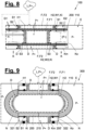
- Figures 8 and 9 show explanatory representations of the effects of the overpressure which is exerted on the liquid in the cavity and in the annular volume during the performance of a material test, in particular the forces (D) generated by this overpressure in the axial direction (A, B), which act on the separations (H1, H2) and are transmitted to the specimen (200) as axial tensile forces as a result of the end sections of the specimen (200) being fixed there.
- the material testing device is in use and that the user has supplied a tubular sample body, in short the tube (200) and secured it in the intended mounting position.
- the material testing device (100, 300) itself or the sample carrier (K, K') itself will generally not include a tubular sample body when delivered to the customer.
- the material testing device may comprise: the pressure supply unit (130) comprising the pressure supply device (131) that provides pressure using a liquid inside the housing (110).
- the material testing device can comprise: the data processing unit (140) comprising the sensor (141) which preferably measures the pressure of the pressure supply unit (130) and/or the sensor (141) which measures the displacement of the pipe (200), and the data processing device (142) which preferably receives and processes numerical data from the sensor (141).
- the sensor (141) can measure or monitor any parameter. The excess pressure of the liquid and the displacement of the pipe are only preferred embodiments for recommended designs of the sensor (141).
- the material testing apparatus particularly the whole-pipe tensile testing apparatus of the present disclosure enables the pipe to be used in its entirety without any processing, and the tensile test is performed inside the casing (110), i.e., inside the casing passage (E).
- the testing process is simplified and more accurate data can be obtained.
- the tube (200) can be positioned inside the housing (110) in the intended mounting position, the housing forming the enclosing body of the testing device, which limits the annular volume outwards in the radial direction.
- the tube (200) can be fastened between two sample carriers, in particular between the first end cap (121) and the second end cap (122) or between the first ring (321) and the second ring (322).
- the other partition, in particular a partition (H1) fixed to the housing (110) can be formed, for example, by an end plate to which the tubular sample body is, for example, welded, glued or otherwise integrally attached.
- the material testing device has two pipe holders (G1, G2) which are designed to fix an end section of the pipe (200) to one of the separations (H1, H2). It is therefore assumed below that the material testing device (100, 300) comprises a sample carrier unit with at least two sample carriers.
- a first sample carrier, in particular the first end cap (121) can be placed on an end portion, in short on one end of the tube (200) and fastened in connection with the end of the housing (110) and seal the interior of the housing (110).
- a second sample carrier, in particular the second end cap (122) can be installed at the opposite end of the tube (200), come into contact with the interior of the housing (110) and move slidably along the interior of the housing (110).
- the sample carrier (K) comprises a tube holder (G) which is designed to grip and hold the end portion of the sample body (200) and in particular forms a clamping tube holder (G).
- FIG. 6 time another preferred embodiment of a sample carrier (K ⁇ ).
- This sample carrier (K ⁇ ) also comprises a pipe holder (G ⁇ ), wherein this pipe holder (G ⁇ ) supports a collar (O) which projects radially from the end section of the sample body (200) and is joined in one piece with the end section and in particular forms an axial stop pipe holder (G ⁇ ).
- the collar (O) can be made in any way.
- a front opening closure element (N) is integrally attached to an end face of the tubular test body.
- the front opening closure element can, for example, consist of the same material as the tube (200) itself, or of a compatible material, and it can be integrally attached, for example by welding or gluing.
- the front opening closure element (N) could also be a pipe closure plug known in practice for an internal overpressure burst test.
- the sample carrier (K, K') has a (first) sealing structure (S, S1) which is formed on the lateral surface (Km).
- the flange (121a) and/or a radial outer side of the outer casing (121b, 122b) forms the lateral surface (Km).
- the first sealing structure (S, S1) is designed as a sealing body, for example as a sealing ring, in particular a plastic or rubber sealing ring with a suitable shape, which is preferably placed on a suitably shaped ring receiving area on the jacket surface (Km).
- the (first) sealing structure (S) can be an annular gap seal formed by a micro-gap between the radial outer contour of the casing surface (Km) and the radial inner contour of the housing passage (E).
- Such an annular gap seal can be provided without a separate sealing body or in addition to a separate sealing body.
- the annular gap seal can have a bearing and guide function.
- the liquid (L) can at least partially enter the micro-gap and cause lubrication. Alternatively, a separate lubricant can be introduced into the micro-gap.
- the sample carrier (K, K ⁇ ) can in particular have a lubricant supply for the micro-gap.
- the sample carrier (K, K ⁇ ) can be used in any design, in particular in the design according to Figures 1-3 and in accordance with Figures 4-6 , have a second sealing structure (S2) which is designed to effect a seal between the sample carrier (K, K') and a radial outer surface of the sample body (200) in the intended mounting position.
- S2 second sealing structure
- sample carrier (K, K ⁇ ) can be in any design, in particular in the design according to Figures 1-3 and in accordance with Figures 4-6 , having a (first) pressure-stable wall section (W1) which forms at least part of the inner side (Ki) of the sample carrier (K, K ⁇ ) (facing the central region of the tube) and extends between the first sealing structure (S1), which acts on the housing passage (E), and a second sealing structure (S2), which acts on a radial outer surface of the sample body (200).
- first sealing structure (S1) which acts on the housing passage (E)
- S2 second sealing structure
- this first wall section (W1) can be formed by the outer frame (121b, 122b).
- the flange (121a) can form the first wall section (W1) partially or completely.
- the first wall section (W1) is formed by the body of the sample carrier ring (321, 322).
- the sample carrier (K) can be designed as an end cap (K, 121, 122) which engages over an end face of a cavity (F1) within the tubular sample body (200) and further engages over an end face of an annular volume (F2) which lies between the radial outer surface of the sample body (200) and the housing passage (E).
- the sample carrier (K) can preferably have a further (third) sealing structure (S3) which is designed to effect a seal between the sample carrier (K, K') and a radial inner surface of the sample body (200) in the intended mounting position.
- S3 further (third) sealing structure
- a sample carrier (K) designed as an end cap (121, 122) comprises a tube holder (G2), wherein this tube holder (G2) has an outer socket (121b) and an inner socket (121c), between which the end section of the sample body can be gripped in a clamping manner.
- the sample carrier (K) can particularly preferably comprise an inclined wall body (121d) which is designed to be subjected to a liquid (L) under excess pressure (P+) on the inside (Ki) of the sample carrier (K) during the performance of a material test and to bring about an actuation or increase of the gripping effect from the pressure application, with which the tube holder (G, G2) fixes the end section of the sample body (200).
- an inclined wall body (121d) which is designed to be subjected to a liquid (L) under excess pressure (P+) on the inside (Ki) of the sample carrier (K) during the performance of a material test and to bring about an actuation or increase of the gripping effect from the pressure application, with which the tube holder (G, G2) fixes the end section of the sample body (200).
- the inclined wall body (121d) is arranged in a cavity of the sample body (200) and acts on a part of the inner frame (121d) via its inclined wall.
- the present disclosure is not limited to this, however.
- the inclined wall body can be arranged singly or in multiple ways. It can be arranged in the region of the cavity (F1) or in the region of the annular volume (F2). It can act directly on the inner frame or the outer frame, or it can in any other form - even indirectly - bring about an actuation or increase of the gripping effect with which the pipe holder (G, G2) fixes the end section of the sample body (200).
- the inclined wall body (121d) can be aligned with the cavity (F1) of the sample body (200) and is designed to be subjected to a liquid under overpressure (P+) in the cavity (F1) during the performance of a material test and to press the inner frame (121c) against the radial inner surface of the sample body (200) from a force (D) generated by the overpressure (P+).
- P+ liquid under overpressure
- the inclined wall body can be arranged in the intended mounting position in alignment with the annular volume (F2) between the test body (200) and the surrounding housing passage (E) and can be designed to be subjected to a liquid under excess pressure (P+) in the annular volume (F2) during the performance of a material test and to press the outer casing (121b) against the radial outer surface of the test body (200) by means of a force (D) generated by the excess pressure (P+).
- P+ liquid under excess pressure
- the force (D) acting on the inclined wall body can also act as a force which pushes the partition (H1, H2) outwards in the axial direction (A, B) - cf.
- Figure 7 Arrows for force (D) in cavity (F1) - and which is transferred to the pipe (200) as a tensile force according to the fixing of the pipe (200) at this separation (H1, H2). This force also acts there as a tensile force or as a corresponding axial tensile stress component in the pipe wall.
- the sample carrier (K) can preferably have a (second) pressure-stable wall section (W2) which forms at least part of the inner side (Ki) of the sample carrier (K, K') and preferably overlaps a space within a sealing structure (S3) which acts on a radial inner surface of the sample body (200).
- a (second) pressure-stable wall section (W2) can be present on the flange (121a) and/or on the inner frame (121c), where analogous to the above embodiments, a force (D) acts in the axial direction, which leads to a tensile force or a proportional tensile stress in the test body (200).
- the first end cap (121) of the sample carrier (K) according to Figure 3 can be attached to one end of the tube (200) and connected to one end of the housing (110) by means of an outer socket (121b).
- the second end cap (122) may have the same or a different configuration. It may be installed at the opposite end of the tube (200) and is preferably connected to the outer socket (122b).
- the tube (200) is positioned in the housing (110) in the intended mounting position, and the flange (121a) is attached to one end of the tube (200).
- the flange (121a) is securely fastened by connecting it to both the one end of the housing (110) and to the tube receptacle, in particular to an external socket (121b), whereby the interior of the housing (110) can be sealed.
- a flange (122a) which is connected to the outer socket (122b) and can come into contact with the interior of the housing (110) and can move along the interior of the housing (110).
- the inner socket (121c), the inclined wall body (121d), the inner socket (122c) and the inclined wall body (122d) can be arranged inside the tube (200).
- the outer socket (121b) and the outer socket (122b) can be arranged between the housing (110) and the tube (200).
- the inner sockets (121c, 122c) may have grooves on their side surfaces into which the projections of the respective flanges (121a, 122a) are inserted.
- the upper and lower surfaces of the inner sockets (121c, 122c) may be inclined.
- the inner sockets (121c, 122c) may have a shape in which the diameter is larger in the portion adjacent to the center of the pipe (200) and gradually decreases in the portion adjacent to the flanges (121a, 122a).
- One end of the inner sockets (121c, 122c) with a larger diameter can come into contact with the inside of the pipe (200), while the other end with a smaller diameter can come into contact with the inclined wall bodies (121d, 122d).
- the inner casings (121c, 122c) can be provided on their outer surfaces with a (third) sealing structure (S, S3), in particular in the form of sealing elements, in order to prevent the applied overpressure and the liquid (L) from escaping.
- a (third) sealing structure (S, S3) in particular in the form of sealing elements, in order to prevent the applied overpressure and the liquid (L) from escaping.
- the inclined wall bodies (121d, 122d) can be installed between the inner sockets (121c, 122c) and the pipe (200).
- the upper, i.e. the radially outward facing surface of the inclined wall bodies can contact the pipe (200), and the axially adjacent surface of the inclined wall bodies can be inclined so as to correspond to the inclined surface of the inner sockets (121c, 122c).
- the inclined wall bodies (121d, 122d) can have a thickness that gradually increases towards the portions adjacent to the flanges (121a, 122a), while having a smaller thickness in the portions adjacent to the center of the pipe (200).
- the outer sleeves (121b, 122b) can be arranged between the housing (110) and the tube (200) to secure the tube (200). When excess pressure is applied, it can limit the radially outward movement and expansion of the tube (200).
- the outer casings (121b, 122b) can have the (first) sealing structure on their radial outer surface and in particular be provided with sealing elements which prevent the applied overpressure and the liquid (L) from escaping.
- the inner sockets (121c, 122c) move towards the flange (121a, 122a) located at the end of the pipe (200) due to the applied pressure. During this movement, the inner sockets (121c, 122c) slide along the inclined surface of the inclined wall bodies (121d, 122d) and exert a strong compressive force on the inclined wall bodies (121d, 122d).
- the first inclined wall body (121d) is firmly supported by the inner socket (121b) located between the housing (110) and the pipe (200).
- the outer socket (121b), the pipe (200) and the inclined wall body (121d) are strongly and firmly secured to the housing (110).
- the pipe (200) remains in firm connection with the housing (110), the outer socket (121b) and the flange (121a), so its end portion is fixed in place and the pipe socket prevents any movement.
- the second inclined wall body (122d) is firmly supported by the second outer socket (122b) which is located between the housing (110) and the pipe (200).
- the outer socket (122b), the pipe (200) and the inclined wall body (122d) are firmly connected to each other so that the pipe (200) is fixed together with the outer socket (122b) and the flange (122a).
- the second end cap (122) moves in the housing passage (E) of the housing (110), which causes an axial displacement of the end section of the tube (200). This allows a tensile test to be carried out on the pipe (200) ( Fig. 3 ).
- the housing (110), the first sample carrier, in particular the first end cap (121) and the second sample carrier, in particular the second end cap (122) can have one or more pressure supply openings (132) to provide pressure from the pressure supply unit (130).
- the pressure supply openings (132) can individually or jointly be a component of the liquid supply (M) or form this.
- the pressure supply opening(s) can also be used for venting or emptying the liquid after completion of the material test.
- the positive pressure applied by the pressure supply device (131) of the pressure supply unit (130) is supplied to the liquid inside the housing (110), namely the fluid pressure chamber (F) in contact with the inside and the outside of the tube (200) through the pressure supply holes (132). This enables tensile tests to be carried out on the tube (200).
- the (first) flange (121a) can be connected to the housing (110) and the outer casing (121b) in any way, in particular by means of bolts, clamps or similar means.
- the (second) flange (122a) can be connected to the outer casing (122b) by any means, in particular by means of screws, clamps or similar means.
- the radial inner surface of the outer mount (121b, 122b) and/or the radial outer surface of the inner mount (121c, 122c) can have a grooved shape, ie a surface structure that increases the gripping effect, in particular comprising a corrugated shape.
- This surface structure, in particular the corrugated shape of the grooves can firmly fix the pipe (200) and thus prevent the movement of the pipe (200) due to the effect of pressure. It can preferably be a component of the clamping pipe holder.
- a preferred embodiment provides that the one The surface structure increasing the gripping effect is arranged in the axial direction of the sample body (200) adjacent to the (second or third) sealing structure (S2, S3), wherein in particular the (second or third) sealing structure (S2, S3) is arranged further towards the central region of the sample body (200).
- Such an arrangement is in Figure 8 for the second and third sealing structures (S2, S3).
- This arrangement is further shown in Figure 3 for the second sealing structure (S2) is outlined by an outline representation of the sealing structure.
- - sealing structure (S2, S3) is arranged in relation to the axial direction (A) of the sample body (200) in the pressure direction BEFORE the surface structure that increases the gripping effect
- the (second or third) sealing structure which acts on the radial outer wall or on the radial inner wall of the sample body (200), separates the liquid in the fluid pressure chamber (F) from the surface structure that increases the gripping effect.
- the (second or third) sealing structure (S2, S3) can be arranged further towards the end section of the sample body (200).
- FIG. 3 This is in Figure 3 for the second and third sealing structure (S2, S3) is represented by a black area.
- This arrangement - sealing structure (S2, S3) is arranged in the pressure direction BEHIND the surface structure that increases the gripping effect in relation to the axial direction (A) of the test body (200) - ensures that the respective sealing structure only has to be pushed a comparatively short distance in the axial direction over the radial outer wall or radial inner wall during assembly.
- This is particularly advantageous if the material test is carried out by untrained personnel who may repeatedly push a sample carrier over the end section of the test body and remove it again in preparation for the test. This is because the sealing structure is not pushed over a groove structure that may be imprinted on the outer wall of the sample body, so that parasitic effects that could arise from damage to the sealing structure (S2, S3) are reduced or prevented.
- a clamping tube holder (G) can have an outer frame (121b) and/or an inner frame (121c), wherein more preferably the outer frame (121b) has a (first) surface structure that increases the gripping effect and/or the inner frame (121c) has a (second) surface structure that increases the gripping effect.
- a second sealing structure (S2) which acts against a radial outer wall of the sample carrier (200), can be arranged in the pressure-acting direction in front of or behind the (first) surface structure increasing the gripping effect, relative to the axial direction (A) of the sample body (200).
- a third sealing structure (S3) which acts against a radial inner wall of the sample carrier (200), can be arranged on the inner frame in front of or behind the (second) surface structure which increases the gripping effect, relative to the axial direction (A) of the sample body (200) in the pressure direction.
- Figures 4 - 6 show a variant of a sample carrier (K ⁇ ) which is designed as a sample carrier ring (K') which overlaps an end face of an annular volume (F2) which lies between the radial outer surface of the sample body (200) and the housing passage (E), and wherein the sample carrier ring (K') is designed to cooperate with an end opening closure element (N).
- the end opening closure element (N) can be present at an end section of the tubular sample body (200) and can, for example, be attached in one piece or be attached in one piece in order to overlap an end face of the cavity (F1) within the tubular sample body (200) and to seal it in a pressure-tight manner.
- the front opening closure element (N) can be placed and fixed on an end section of the tubular sample body (200), whereby a radial collar (O) is formed which projects in the radial direction beyond a radial wall of the sample body (200).
- the tensile testing apparatus described in the present disclosure can be used when both ends of the tube (200) are open.
- both ends of the tube (200) are closed, as shown in the Fig. 4 to 6
- a hole for inserting the tube (200) is formed in the center of the first specimen ring (321) and the second specimen ring (322), and the tube (200) can be inserted into the hole and fixed.
- the fixing can be done in any way.
- a sample body ring (321, 322) comprises an axial stop tube holder (G ⁇ ) which is designed to support a collar (O) which projects radially from the end section of the sample body (200) and is preferably joined integrally to the end section.
- G ⁇ axial stop tube holder
- O collar
- the material testing device in particular the whole-tube tensile testing device of the present disclosure, can be securely attached to tubes (200) of various shapes. This enables the testing of a wider range of tube configurations (200) and maximizes the versatility of the device.
- the present disclosure can be used both in cases where the tube (200) has holes and in cases where it does not have holes.
- the housing (110), the first partition/the first sample carrier/the first end cap (121) and the second partition/the second sample carrier/the second end cap (122) may each have pressure supply holes (132) which designed to provide pressurized fluid (L) for the tensile test.
- the pressure supply port (132) formed in the housing (110) supplies the pipe (200) with external pressure, while the pressure supply port (132) formed in the partitions, particularly in the first end cap (121) and the second end cap (122), supplies the pipe (200) with internal pressure to perform the tensile test.
- the external and internal pressures applied to the pipe (200) may be the same or different, depending on the purpose of the tensile test.
- the pressure supply hole (132) formed in the housing (110) or the pressure supply hole (132) provided in a partition (H1, H2), in particular in an end cap (121, 122), supplies the pressure or the pressurized liquid (L) for carrying out the tensile test.
- the pressure for carrying out the tensile test on the pipe (200) is particularly preferably supplied through the pressure supply opening (132) formed in the housing (110). Since only one pressure supply hole (132) is used in this case, both internal and external and pressurized fluid (L) are supplied simultaneously.
- the data processing unit (140) may include the sensor (141) for measuring pressure data from the pressure supply unit (130) and the displacement of the tube (200), and a data processing device (142) which preferably receives and processes numerical data from the sensor (141).
- the data processing unit (140) receives data, preferably numerical data, obtained from the sensor (141) which detects the pressure supplied by the pressure supply device (131) of the pressure supply unit (130). supplied pressure data and/or the displacement of the tube (200) within the housing (110).
- the received data are processed by the data processing device (142) and can be presented to the user, for example, graphically or digitally processed.
Landscapes
- Physics & Mathematics (AREA)
- Health & Medical Sciences (AREA)
- Life Sciences & Earth Sciences (AREA)
- Chemical & Material Sciences (AREA)
- Analytical Chemistry (AREA)
- Biochemistry (AREA)
- General Health & Medical Sciences (AREA)
- General Physics & Mathematics (AREA)
- Immunology (AREA)
- Pathology (AREA)
- Investigating Strength Of Materials By Application Of Mechanical Stress (AREA)
Claims (15)
- Support d'échantillon (K, K') destiné à recevoir une partie d'extrémité d'un corps d'échantillon tubulaire (200) pour la réalisation d'un test de capacité de charge, le support d'échantillon (K, K') ayant une face intérieure (Ki) qui, dans la position de montage prévue, est orientée vers une zone centrale du corps d'échantillon (200) à tester, ainsi qu'un côté extérieur (Ko) opposé dans la direction axiale (A, B) du corps d'échantillon (200) et une surface d'enveloppe (Km) entre le côté intérieur et le côté extérieur, le support d'échantillon (K, K') comprenant:- un logement de tube (G, G2, G') qui est conçu pour fixer la partie d'extrémité du corps d'échantillon (200) sur le support d'échantillon (K) ;caractérisé en ce que- le support d'échantillon (K, K') est adapté pour être reçu dans un passage de boîtier environnant (E) avec un contact annulaire par rapport au passage de boîtier (E), et- en ce que le support d'échantillon (K, K') comprend en outre une structure d'étanchéité annulaire (S, S1) qui est disposée sur la surface d'enveloppe (Km) du support d'échantillon (K, K'), la structure d'étanchéité (S, S1) étant conçue à cet effet,▪ à former un joint d'étanchéité annulaire par rapport au passage du boîtier (E), et▪ à permettre un déplacement (T) du porte-échantillon (K, K') dans la direction axiale (A, B) le long du passage de boîtier (E).
- Porte-échantillon (K, K') selon la revendication précédente, dans lequel,- le logement de tube est adapté pour recevoir et maintenir par saisie la partie d'extrémité du corps d'échantillon (200) et forme en particulier un logement de tube de serrage (G) ; ET/OU- le logement de tube est conçu pour soutenir un collet (O) dépassant dans la direction radiale de la section d'extrémité du corps d'échantillon (200) et assemblé de préférence d'une seule pièce avec la section d'extrémité, et forme en particulier un logement de tube à butée axiale (G').
- Porte-échantillon (K, K') selon l'une des revendications précédentes, dans lequel la structure d'étanchéité (S, S1) est réalisée sur la surface latérale (Km) par- un corps d'étanchéité ; ET/OU- un joint d'étanchéité à fente annulaire formé par une microfente entre le contour radial extérieur de la surface d'enveloppe (Km) et le contour radial intérieur du passage de boîtier (E).
- Porte-échantillon (K, K') selon l'une des revendications précédentes, dans lequel le porte-échantillon (K, K') présente une deuxième structure d'étanchéité (S2) qui est conçue pour assurer une étanchéité entre le porte-échantillon (K, K') et une surface extérieure radiale du corps d'échantillon (200) dans la position de montage prévue.
- Porte-échantillon (K, K') selon l'une des revendications précédentes 3 ou 4, dans lequel le porte-échantillon (K)- comprend une partie de paroi résistante à la pression (W1) formant au moins une partie de l'intérieur (Ki) du porte-échantillon (K, K') et s'étendant entre la première structure d'étanchéité (S1) agissant sur le passage du boîtier (E) et une seconde structure d'étanchéité (S2) agissant sur une surface radialement extérieure du corps d'échantillon (200) ; ET/OU- est formé comme un capuchon d'extrémité (K, 121, 122) qui couvre une face d'extrémité d'une cavité (F1) à l'intérieur du corps d'échantillon tubulaire (200) et qui couvre en outre une face d'extrémité d'un volume annulaire (F2) situé entre la surface radialement extérieure du corps d'échantillon (200) et le passage de boîtier (E) ; ET/OU- comprend une autre structure d'étanchéité (S3) qui est conçue pour assurer l'étanchéité entre le porte-échantillon (K, K') et une surface radialement intérieure du corps d'échantillon (200) dans la position de montage prévue.
- Porte-échantillon (K) selon l'une des revendications précédentes, dans lequel le logement tubulaire (G2) présente une monture extérieure (121b) et une monture intérieure (121c) entre lesquelles la portion d'extrémité du corps d'échantillon peut être saisie par serrage.
- Porte-échantillon (K) selon l'une quelconque des revendications précédentes, dans lequel le porte-échantillon (K) comprend au moins un corps à paroi inclinée (121d) qui est conçu pour être alimenté en liquide (L) sous surpression (P+) sur la face interne (Ki) du porte-échantillon (K) pendant l'exécution d'un test de matériau et pour provoquer, à partir de l'alimentation en pression, un actionnement ou une augmentation de l'effet de préhension avec lequel le logement tubulaire (G, G2) fixe la section d'extrémité du corps d'échantillon (200).
- Porte-échantillon (K, K') selon l'une quelconque des revendications précédentes 1 à 4, dans lequel le porte-échantillon est réalisé sous la forme d'une bague porte-échantillon (K') qui couvre une surface frontale d'un volume annulaire (F2) qui se trouve entre la surface radialement extérieure du corps d'échantillon (200) et le passage de boîtier (E), et dans lequel la bague porte-échantillon (K') est réalisée à cet effet, coopérer avec un élément de fermeture d'ouverture d'extrémité (N), l'élément de fermeture d'ouverture d'extrémité (N) pouvant être ajouté ou étant ajouté d'un seul tenant, en particulier à une partie d'extrémité du corps d'échantillon tubulaire (200), afin de couvrir une surface d'extrémité d'une cavité (F1) à l'intérieur du corps d'échantillon tubulaire (200) et de la fermer de manière étanche à la pression.
- Dispositif d'essai de matériau pour effectuer un essai de résistance à la charge sur une éprouvette tubulaire (200), le dispositif d'essai de matériau (100) comprenant :- Un boîtier (110) résistant à la pression avec un passage de boîtier (E) ;- A l'intérieur d'une partie du passage de boîtier (E), une chambre de pression de fluide (F) séparée ou séparable, dans laquelle l'éprouvette tubulaire (200) peut être introduite dans une position de montage prévue, la chambre de pression de fluide (F) comprenant d'une part une cavité (F1) à l'intérieur de l'éprouvette tubulaire (200) et d'autre part un volume annulaire (F2) entre la surface radialement extérieure de l'éprouvette (200) et le passage de boîtier (E) ;- Une fixation pour une première partie d'extrémité du support d'échantillon tubulaire (200) à une première séparation (H1) de la chambre de pression de fluide (F) au moyen d'un premier logement de tube (G1) ;- un support d'échantillon (K, K') avec un deuxième logement tubulaire (G, G2, G'), le support d'échantillon (K, K') pouvant être disposé ou étant disposé sur une zone distanciée de la première extrémité axiale du passage de boîtier (E) et formant au moins en partie la deuxième séparation (H2) de la chambre de pression de fluide (F) ;- Et dans lequel le corps d'échantillon tubulaire (200) peut être fixé dans la position de montage prévue entre le premier logement tubulaire (G1) et le deuxième logement tubulaire (G2) ;- Et dans lequel le dispositif d'essai de matériau (100) présente une alimentation en liquide (M) qui est conçue pour que la cavité (F1) et le volume annulaire (F2) de la chambre de pression de fluide (F) puissent être remplis de liquide (L), que le liquide (L) puisse être soumis à une surpression (P+) dans la cavité (F1) et dans le volume annulaire (F2) et que d'autres liquides (L) pouvant être soumis à une surpression (P+) puissent être introduits dans la cavité (F1) ainsi que dans le volume annulaire (F2) ;- et le porte-échantillon (K, K') pouvant être déplacé dans le passage du boîtier (E) dans la direction axiale (A, B) du corps d'échantillon (200), avec l'introduction supplémentaire de liquide (L) soumis à une surpression (P+), y compris le deuxième logement tubulaire (G2) ainsi qu'avec l'entraînement de la section d'extrémité du corps d'échantillon (200) qui y est fixée.
- Dispositif d'essai de matériaux selon la revendication précédente, dans lequel le porte-échantillon (K) est réalisé selon l'une des revendications précédentes.
- Dispositif d'essai de matériaux selon l'une des revendications précédentes, dans lequel le dispositif d'essai de matériaux (100, 300)- comporte une unité d'alimentation en pression (130) comprenant notamment un dispositif d'alimentation en pression (131, PSD) qui fournit une pression (P+) en utilisant un liquide (L) dans la chambre de pression de fluide (F) à l'intérieur du boîtier (110) ; ET/OU- le dispositif d'essai de matériau (100, 300) comprend un dispositif de traitement de données (142, DPD) qui reçoit et traite des signaux et/ou des données, en particulier des données numériques, provenant de capteurs (141) ; ET/OU- comprend une unité de traitement de données (140) formée ou connectée à des capteurs (141), lesdits capteurs (141) détectant ou surveillant au moins un paramètre pendant l'exécution d'un test de matériau, et dans lequel ledit au moins un paramètre comprend notamment▪ une pression dans la chambre de pression de fluide (F) et/ou une pression de l'unité d'alimentation en pression (130) ; ET/OU▪ un déplacement d'au moins une partie de l'échantillon tubulaire (200), en particulier une partie d'extrémité de l'échantillon tubulaire (200) ; ET/OU▪ une contrainte de traction axiale dans la paroi du corps d'échantillon tubulaire (200) ; ET/OU▪ une déformation, en particulier un allongement de l'éprouvette tubulaire (200) ; ET/OU▪ une énergie ou une puissance dépensée pour l'introduction du liquide et/ou pour le déplacement de la partie d'extrémité du corps d'échantillon (200) dans la direction axiale (A, B).
- Dispositif d'essai de matériaux selon l'une quelconque des revendications précédentes, dans lequel- le dispositif d'essai de matériau (100) comprend au moins un support d'échantillon (K) qui est formé comme un capuchon d'extrémité (121, 122) ; ET/OU- le dispositif d'essai de matériau (300) comprend au moins un support d'échantillon (K') qui est réalisé sous la forme d'une bague (321, 322) et qui coopère avec un élément de fermeture d'ouverture frontale (N) qui est notamment ajouté d'un seul tenant à une partie d'extrémité associée du corps d'échantillon (200).
- Procédé d'essai de matériau pour tester la capacité de charge d'une éprouvette tubulaire (200), le procédé d'essai comprenant les étapes suivantes :- Fournir un boîtier (110) résistant à la pression avec un passage de boîtier (E) ;- Introduction de l'échantillon tubulaire (200) dans le passage du boîtier (E) ;- séparer une chambre de pression de fluide (F) à l'intérieur d'une partie du passage de boîtier (E), la chambre de pression de fluide (F) comprenant d'une part une cavité (F1) dans le corps d'échantillon tubulaire (200) et d'autre part un volume annulaire (F2) entre la surface radialement extérieure du corps d'échantillon (200) et le passage de boîtier (E) ;- fixation de deux parties d'extrémité du corps d'échantillon (200) aux séparations (H1, H2) opposées l'une à l'autre dans la direction axiale (A, B) du corps d'échantillon (200) de la chambre de pression de fluide (F) ;- Introduction d'un liquide (L) dans la chambre de pression de fluide (F), de sorte que tant la cavité (F1) que le volume annulaire (F2) sont ou seront remplis de liquide (L) ;- Mise sous pression du liquide (L) dans la chambre de pression de fluide (F) avec une surpression (P+) ;- étirer l'éprouvette tubulaire (200) dans une direction axiale (A, B) en continuant à introduire du liquide (L) soumis à une surpression (P+) dans la cavité (F1) ainsi que dans le volume annulaire (F2), le volume de la chambre de pression de fluide (F) s'élargissant et au moins une séparation (H1, H2) de la chambre de pression de fluide (F) se déplaçant dans la direction axiale (A, B) de l'éprouvette tubulaire (200) en entraînant la partie d'extrémité de l'éprouvette (200) qui y est fixée ;- mesurer ou surveiller au moins un paramètre afin d'évaluer une caractéristique de capacité de charge de l'éprouvette (200) pendant la mise sous pression.
- Procédé d'essai de matériau selon la revendication précédente, dans lequel- au moins une séparation (H1, H2) de la chambre de pression de fluide (F) est formée au moins en partie par un porte-échantillon (K, K') selon l'une quelconque des revendications précédentes 1 à 14 ; ET/OU dans lequel- le procédé d'essai de matériau est mis en oeuvre avec un dispositif d'essai de matériau selon l'une quelconque des revendications 9 à 12 précédentes.
- Procédé d'essai de matériaux selon l'une quelconque des revendications précédentes, dans lequel l'éprouvette tubulaire (200) est formée par :- Au moins un tube (200) réalisé en un matériau synthétique, notamment un tube en matière plastique ; ET/OU- Au moins un tube (200) fait d'un matériau composite, en particulier un tube (200) comprenant un matériau fibreux noyé dans une matrice ; ET/OU- Un tube relié ou assemblé à partir de deux éprouvettes partielles (200, 200'), les éprouvettes partielles (200, 200') étant, en particulier sur leurs faces frontales orientées vers la zone médiane▪ sont assemblés ou couplés entre eux par une liaison (210) ; OU▪ sont reliés entre eux par un couplage de tubes.
Applications Claiming Priority (2)
| Application Number | Priority Date | Filing Date | Title |
|---|---|---|---|
| KR1020220140318A KR102901685B1 (ko) | 2022-10-27 | 2022-10-27 | 유체 압력을 이용한 전체 배관 또는 배관/연결부 인장시험장치 |
| PCT/EP2023/079999 WO2024089210A1 (fr) | 2022-10-27 | 2023-10-26 | Technique d'essai pour un échantillon d'essai tubulaire faisant intervenir une pression de liquide |
Publications (3)
| Publication Number | Publication Date |
|---|---|
| EP4409258A1 EP4409258A1 (fr) | 2024-08-07 |
| EP4409258B1 true EP4409258B1 (fr) | 2024-11-06 |
| EP4409258C0 EP4409258C0 (fr) | 2024-11-06 |
Family
ID=88838915
Family Applications (1)
| Application Number | Title | Priority Date | Filing Date |
|---|---|---|---|
| EP23808666.4A Active EP4409258B1 (fr) | 2022-10-27 | 2023-10-26 | Technique d'essai pour un échantillon d'essai tubulaire faisant intervenir une pression de liquide |
Country Status (3)
| Country | Link |
|---|---|
| EP (1) | EP4409258B1 (fr) |
| KR (1) | KR102901685B1 (fr) |
| WO (1) | WO2024089210A1 (fr) |
Family Cites Families (7)
| Publication number | Priority date | Publication date | Assignee | Title |
|---|---|---|---|---|
| JP2009122024A (ja) * | 2007-11-16 | 2009-06-04 | Hitachi Ltd | 配管耐圧試験用閉止装置および配管耐圧試験用治具 |
| KR200468878Y1 (ko) * | 2011-11-08 | 2013-09-05 | 삼성중공업 주식회사 | 수압 테스트 어셈블리 |
| KR101465388B1 (ko) | 2014-02-14 | 2014-11-25 | 성균관대학교산학협력단 | 파괴저항 시험용 지그 및 이를 이용한 파괴저항 시험장치 |
| KR101700999B1 (ko) | 2014-07-01 | 2017-02-01 | 성균관대학교산학협력단 | 실배관 시편의 파괴인성 시험용 인장 및 압축시험장치 |
| JP2017219338A (ja) * | 2016-06-03 | 2017-12-14 | 株式会社Ihi | 引張試験装置及び試験片評価システム |
| KR20190133518A (ko) * | 2018-05-23 | 2019-12-03 | 삼성중공업 주식회사 | 누출 감지장치 |
| CN114414380A (zh) * | 2022-02-24 | 2022-04-29 | 华南农业大学 | 测量结构工程用的复合材料管轴向拉伸性能的试验装置和试验方法 |
-
2022
- 2022-10-27 KR KR1020220140318A patent/KR102901685B1/ko active Active
-
2023
- 2023-10-26 EP EP23808666.4A patent/EP4409258B1/fr active Active
- 2023-10-26 WO PCT/EP2023/079999 patent/WO2024089210A1/fr not_active Ceased
Also Published As
| Publication number | Publication date |
|---|---|
| EP4409258A1 (fr) | 2024-08-07 |
| KR20240059264A (ko) | 2024-05-07 |
| KR102901685B1 (ko) | 2025-12-24 |
| EP4409258C0 (fr) | 2024-11-06 |
| WO2024089210A1 (fr) | 2024-05-02 |
Similar Documents
| Publication | Publication Date | Title |
|---|---|---|
| DE69622374T2 (de) | Axialprägegerät mit stabilisierender pinne | |
| DE3850549T3 (de) | Schlauchkupplung. | |
| DE19653745B4 (de) | Schnellkupplung | |
| DE3415627A1 (de) | Rohrpruefgeraet | |
| DE3009168C2 (de) | Vorrichtung zum Druckprüfen von Schlauchleitungen mit Metallarmaturen | |
| DE102006001425B4 (de) | Rohrprüfanlage | |
| EP4409258B1 (fr) | Technique d'essai pour un échantillon d'essai tubulaire faisant intervenir une pression de liquide | |
| DE10344544B3 (de) | Vorrichtung zur mechanischen Werkstoffprüfung | |
| DE3924345A1 (de) | Einspannvorrichtung fuer die zugpruefung von proben bei hohen temperaturen | |
| DE3904903C2 (de) | Vorrichtung für das Einspannen von dünnwandigen Hohlprofilen | |
| DE69102678T2 (de) | Verfahren und Vorrichtung zur Prüfung des Endes eines geschlossenen Rohres. | |
| EP0505721A1 (fr) | Dispositif pour tester l'étanchéité de jonctions de tubes | |
| DE1525473C3 (de) | Dicht- und Spannkopf | |
| EP0108722B1 (fr) | Manchon pour tuyaux | |
| EP3884254B1 (fr) | Procédé de fabrication d'une conduite hydraulique haute-pression, et également presse radiale pour mettre en oeuvre le procédé | |
| DE3144385C2 (de) | Überschiebemuffe | |
| DE102005035857B4 (de) | Druckzylinder | |
| DE2650371B2 (de) | Kupplungsmuffe aus Kunststoff für eine zugfeste Rohrverbindung | |
| DE2917668C2 (de) | Halteanordnung zur mechanischen Prüfung von Kunststoffrohren | |
| EP1855097A1 (fr) | Dispositif et procédé destinés à la vérification de la stabilité de moyeux d'enroulement | |
| DE3243201C2 (de) | Presse zum Prüfen von Rohren | |
| DE29801024U1 (de) | Vorrichtung zum Verschließen eines mit einem endseitigen Formstück versehenen Rohres | |
| DE20314761U1 (de) | Vorrichtung zur mechanischen Werkstoffprüfung | |
| DE102015207875A1 (de) | Spannvorrichtung, Verfahren für eine Spannvorrichtung und Verwendung einer Spannvorrichtung | |
| DE102020101262B4 (de) | Kupplungseinrichtung zum Verbinden von hydraulischen Leitungen und Prüfsystem mit einer Kupplungseinrichtung |
Legal Events
| Date | Code | Title | Description |
|---|---|---|---|
| STAA | Information on the status of an ep patent application or granted ep patent |
Free format text: STATUS: UNKNOWN |
|
| STAA | Information on the status of an ep patent application or granted ep patent |
Free format text: STATUS: THE INTERNATIONAL PUBLICATION HAS BEEN MADE |
|
| PUAI | Public reference made under article 153(3) epc to a published international application that has entered the european phase |
Free format text: ORIGINAL CODE: 0009012 |
|
| STAA | Information on the status of an ep patent application or granted ep patent |
Free format text: STATUS: REQUEST FOR EXAMINATION WAS MADE |
|
| 17P | Request for examination filed |
Effective date: 20240430 |
|
| AK | Designated contracting states |
Kind code of ref document: A1 Designated state(s): AL AT BE BG CH CY CZ DE DK EE ES FI FR GB GR HR HU IE IS IT LI LT LU LV MC ME MK MT NL NO PL PT RO RS SE SI SK SM TR |
|
| GRAP | Despatch of communication of intention to grant a patent |
Free format text: ORIGINAL CODE: EPIDOSNIGR1 |
|
| STAA | Information on the status of an ep patent application or granted ep patent |
Free format text: STATUS: GRANT OF PATENT IS INTENDED |
|
| GRAS | Grant fee paid |
Free format text: ORIGINAL CODE: EPIDOSNIGR3 |
|
| GRAA | (expected) grant |
Free format text: ORIGINAL CODE: 0009210 |
|
| STAA | Information on the status of an ep patent application or granted ep patent |
Free format text: STATUS: THE PATENT HAS BEEN GRANTED |
|
| DAV | Request for validation of the european patent (deleted) | ||
| DAX | Request for extension of the european patent (deleted) | ||
| INTG | Intention to grant announced |
Effective date: 20240923 |
|
| AK | Designated contracting states |
Kind code of ref document: B1 Designated state(s): AL AT BE BG CH CY CZ DE DK EE ES FI FR GB GR HR HU IE IS IT LI LT LU LV MC ME MK MT NL NO PL PT RO RS SE SI SK SM TR |
|
| REG | Reference to a national code |
Ref country code: GB Ref legal event code: FG4D Free format text: NOT ENGLISH |
|
| REG | Reference to a national code |
Ref country code: CH Ref legal event code: EP |
|
| REG | Reference to a national code |
Ref country code: DE Ref legal event code: R096 Ref document number: 502023000282 Country of ref document: DE |
|
| REG | Reference to a national code |
Ref country code: IE Ref legal event code: FG4D Free format text: LANGUAGE OF EP DOCUMENT: GERMAN |
|
| U01 | Request for unitary effect filed |
Effective date: 20241204 |
|
| U07 | Unitary effect registered |
Designated state(s): AT BE BG DE DK EE FI FR IT LT LU LV MT NL PT RO SE SI Effective date: 20241212 |
|
| PG25 | Lapsed in a contracting state [announced via postgrant information from national office to epo] |
Ref country code: HR Free format text: LAPSE BECAUSE OF FAILURE TO SUBMIT A TRANSLATION OF THE DESCRIPTION OR TO PAY THE FEE WITHIN THE PRESCRIBED TIME-LIMIT Effective date: 20241106 Ref country code: IS Free format text: LAPSE BECAUSE OF FAILURE TO SUBMIT A TRANSLATION OF THE DESCRIPTION OR TO PAY THE FEE WITHIN THE PRESCRIBED TIME-LIMIT Effective date: 20250306 |
|
| PG25 | Lapsed in a contracting state [announced via postgrant information from national office to epo] |
Ref country code: ES Free format text: LAPSE BECAUSE OF FAILURE TO SUBMIT A TRANSLATION OF THE DESCRIPTION OR TO PAY THE FEE WITHIN THE PRESCRIBED TIME-LIMIT Effective date: 20241106 |
|
| PG25 | Lapsed in a contracting state [announced via postgrant information from national office to epo] |
Ref country code: NO Free format text: LAPSE BECAUSE OF FAILURE TO SUBMIT A TRANSLATION OF THE DESCRIPTION OR TO PAY THE FEE WITHIN THE PRESCRIBED TIME-LIMIT Effective date: 20250206 |
|
| PG25 | Lapsed in a contracting state [announced via postgrant information from national office to epo] |
Ref country code: GR Free format text: LAPSE BECAUSE OF FAILURE TO SUBMIT A TRANSLATION OF THE DESCRIPTION OR TO PAY THE FEE WITHIN THE PRESCRIBED TIME-LIMIT Effective date: 20250207 |
|
| PG25 | Lapsed in a contracting state [announced via postgrant information from national office to epo] |
Ref country code: PL Free format text: LAPSE BECAUSE OF FAILURE TO SUBMIT A TRANSLATION OF THE DESCRIPTION OR TO PAY THE FEE WITHIN THE PRESCRIBED TIME-LIMIT Effective date: 20241106 |
|
| PG25 | Lapsed in a contracting state [announced via postgrant information from national office to epo] |
Ref country code: RS Free format text: LAPSE BECAUSE OF FAILURE TO SUBMIT A TRANSLATION OF THE DESCRIPTION OR TO PAY THE FEE WITHIN THE PRESCRIBED TIME-LIMIT Effective date: 20250206 |
|
| PG25 | Lapsed in a contracting state [announced via postgrant information from national office to epo] |
Ref country code: SM Free format text: LAPSE BECAUSE OF FAILURE TO SUBMIT A TRANSLATION OF THE DESCRIPTION OR TO PAY THE FEE WITHIN THE PRESCRIBED TIME-LIMIT Effective date: 20241106 |
|
| PG25 | Lapsed in a contracting state [announced via postgrant information from national office to epo] |
Ref country code: SK Free format text: LAPSE BECAUSE OF FAILURE TO SUBMIT A TRANSLATION OF THE DESCRIPTION OR TO PAY THE FEE WITHIN THE PRESCRIBED TIME-LIMIT Effective date: 20241106 |
|
| PG25 | Lapsed in a contracting state [announced via postgrant information from national office to epo] |
Ref country code: CZ Free format text: LAPSE BECAUSE OF FAILURE TO SUBMIT A TRANSLATION OF THE DESCRIPTION OR TO PAY THE FEE WITHIN THE PRESCRIBED TIME-LIMIT Effective date: 20241106 |
|
| PLBE | No opposition filed within time limit |
Free format text: ORIGINAL CODE: 0009261 |
|
| STAA | Information on the status of an ep patent application or granted ep patent |
Free format text: STATUS: NO OPPOSITION FILED WITHIN TIME LIMIT |
|
| 26N | No opposition filed |
Effective date: 20250807 |
|
| U20 | Renewal fee for the european patent with unitary effect paid |
Year of fee payment: 3 Effective date: 20251027 |