EP4403731A1 - Dispositif de fermeture - Google Patents
Dispositif de fermeture Download PDFInfo
- Publication number
- EP4403731A1 EP4403731A1 EP24153021.1A EP24153021A EP4403731A1 EP 4403731 A1 EP4403731 A1 EP 4403731A1 EP 24153021 A EP24153021 A EP 24153021A EP 4403731 A1 EP4403731 A1 EP 4403731A1
- Authority
- EP
- European Patent Office
- Prior art keywords
- locking
- coupling
- actuating element
- door
- slide
- Prior art date
- Legal status (The legal status is an assumption and is not a legal conclusion. Google has not performed a legal analysis and makes no representation as to the accuracy of the status listed.)
- Pending
Links
Images


Classifications
-
- E—FIXED CONSTRUCTIONS
- E05—LOCKS; KEYS; WINDOW OR DOOR FITTINGS; SAFES
- E05B—LOCKS; ACCESSORIES THEREFOR; HANDCUFFS
- E05B41/00—Locks with visible indication as to whether the lock is locked or unlocked
-
- E—FIXED CONSTRUCTIONS
- E05—LOCKS; KEYS; WINDOW OR DOOR FITTINGS; SAFES
- E05B—LOCKS; ACCESSORIES THEREFOR; HANDCUFFS
- E05B63/00—Locks or fastenings with special structural characteristics
- E05B63/14—Arrangement of several locks or locks with several bolts, e.g. arranged one behind the other
- E05B63/143—Arrangement of several locks, e.g. in parallel or series, on one or more wings
-
- E—FIXED CONSTRUCTIONS
- E05—LOCKS; KEYS; WINDOW OR DOOR FITTINGS; SAFES
- E05B—LOCKS; ACCESSORIES THEREFOR; HANDCUFFS
- E05B83/00—Vehicle locks specially adapted for particular types of wing or vehicle
- E05B83/16—Locks for luggage compartments, car boot lids or car bonnets
- E05B83/22—Locks for luggage compartments, car boot lids or car bonnets for luggage compartments at the side of the vehicle, e.g. of buses or camper vans
-
- E—FIXED CONSTRUCTIONS
- E05—LOCKS; KEYS; WINDOW OR DOOR FITTINGS; SAFES
- E05B—LOCKS; ACCESSORIES THEREFOR; HANDCUFFS
- E05B83/00—Vehicle locks specially adapted for particular types of wing or vehicle
- E05B83/36—Locks for passenger or like doors
- E05B83/44—Locks for passenger or like doors for recreational vehicles, e.g. caravans or camper vans
-
- E—FIXED CONSTRUCTIONS
- E05—LOCKS; KEYS; WINDOW OR DOOR FITTINGS; SAFES
- E05C—BOLTS OR FASTENING DEVICES FOR WINGS, SPECIALLY FOR DOORS OR WINDOWS
- E05C9/00—Arrangements of simultaneously actuated bolts or other securing devices at well-separated positions on the same wing
- E05C9/002—Arrangements of simultaneously actuated bolts or other securing devices at well-separated positions on the same wing with arrangements allowing the wing to be slam-shut, e.g. by securing elements with latching action
-
- E—FIXED CONSTRUCTIONS
- E05—LOCKS; KEYS; WINDOW OR DOOR FITTINGS; SAFES
- E05C—BOLTS OR FASTENING DEVICES FOR WINGS, SPECIALLY FOR DOORS OR WINDOWS
- E05C9/00—Arrangements of simultaneously actuated bolts or other securing devices at well-separated positions on the same wing
- E05C9/04—Arrangements of simultaneously actuated bolts or other securing devices at well-separated positions on the same wing with two sliding bars moved in opposite directions when fastening or unfastening
- E05C9/043—Arrangements of simultaneously actuated bolts or other securing devices at well-separated positions on the same wing with two sliding bars moved in opposite directions when fastening or unfastening with crank pins and connecting rods
Definitions
- the invention relates to a locking device for locking a door, in particular a door of a caravan or mobile home, against a door frame with at least two locking latches, each of which has a locking slide that is pre-tensioned by a spring in the direction of a locking position and automatically locks, and with an actuating element that is coupled to the locking slides for unlocking the locking latches.
- Corresponding locking devices can be used in various areas of technology.
- One possible area of application is the doors of a caravan or mobile home. These doors usually have to be secured to a door frame at several locking points. locked to ensure that the sometimes large doors are reliably locked and that the seal arranged between the door and the door frame can be reliably compressed.
- corresponding locking devices often also have several latches which are arranged one below the other on the inside of the door in the area of the door edge opposite the door hinges so that the door can be reliably locked to the door frame over its entire height.
- at least two latches are used, with one arranged in the upper area and the other in the lower area of the door.
- a door does not necessarily have to be a door in the true sense of the word; flaps, in particular storage flaps, hatches, covers or windows are also included under the term door.
- the locking latches each have a locking slider that can be moved, in particular in a linear direction, back and forth between a locking position and an unlocking position.
- the locking slider In the locking position, the locking slider can reach behind the frame of the door and thus fix the door in place relative to the door frame.
- the unlocking position the locking sliders are retracted so that they no longer reach behind the frame of the door and the door can therefore be opened. It is also known to pre-tension the locking sliders of the locking latches into the locking position, for which each locking latch can be equipped with a spring.
- the locking device thus enables the door to be locked automatically and it is sufficient to close the door or slam it shut with a certain amount of force depending on the pre-tensioning force of the spring. Active operation of the latches or locking slides is not necessary for this.
- the invention has the object of specifying a locking device with which a reliable locking of the door can be ensured.
- actuating element has a locking indicator and the locking latches are each mechanically coupled to the actuating element by means of the locking indicator to indicate correct locking of the locking slides.
- the locking indicator makes it very easy to see whether all latches are in the locking position and, accordingly, whether all locking slides are reliably engaging behind the door frame to lock the door. In this respect, it can be determined at a glance whether the door needs to be pushed in again or whether the door is already reliably locked at all locking points.
- the coupling between the actuating element and the locking latches or the locking slides is therefore bidirectional in nature. This means that it is not only possible to move the locking slides into the unlocking position via the actuating element, but that a movement of the locking slides also leads to a movement of the actuating element.
- the locking slides are moved by the door frame against the force of the spring in the direction of the unlocking position and thus also the actuating element. This The movement of the locking slides in the direction of the unlocking position can thus be recognized on the actuating element.
- the actuating element also moves accordingly. Due to the bidirectional coupling of the latches or the locking slides and the actuating element, the position of the locking slides can be determined directly from the position of the actuating element and it can be seen at a glance whether the door is reliably locked or not.
- the actuating element is bidirectionally coupled to the or all of the locking slides. Such coupling does not make it possible to move the locking slides independently of the actuating element. Rather, the actuating element can be coupled to the locking slides both in the direction of the locking position and in the direction of the unlocking position. Since when the door is closed, the locking slides are first pressed by the frame in the direction of the unlocking position and then spring back towards the locking position by the spring, both movements also lead to a movement of the actuating element and it is not possible to move the locking slides or the actuating element independently of one another. The actuating element and the locking slides can therefore be forcibly coupled to one another. Minor relative movements, e.g. due to tolerances or a certain amount of play between the components, are of course possible.
- the actuating element can also be moved back and forth between a locking position and an unlocking position, in particular rotated back and forth.
- the coupling between the actuating element and the locking latches or locking slides allows the locking element to be moved back and forth between a locking position and an unlocking position.
- a movement of the actuating element leads directly to a corresponding movement of the locking slide, and a movement of the locking slide leads to a corresponding movement of the actuating element.
- an intuitive unlocking of the locking latches can be achieved in the manner of a latch or knob operation.
- it can have an actuating handle, via which the actuating element can be moved by hand, in particular rotated back and forth by hand.
- the actuating element is pre-tensioned into the locking position via the springs of the locking latches. Due to the forced coupling of the locking latches or the locking slide with the actuating element, the actuating element can be pre-tensioned into the locking position via the springs of the locking slides. If the actuating element is thus moved manually from the locking position to the unlocking position, it can automatically spring back into the locking position after being released. It is therefore not necessary for the actuating element itself to be pre-tensioned via its own pre-tensioning element or spring.
- the locking indicator has an indicator surface that is only visible in the unlocking position.
- the indicator surface can provide visual feedback on the position of the actuating element and thus also on the locking status of the latches.
- the indicator surface can be visible when at least one latch slide is not in the locking position, so that the indicator surface can be used to directly detect when the door is not locked or not yet correctly locked.
- the indicator surface can have a signal color so that an incorrect The locking state cannot be overlooked.
- the locking indicator can have a fixed section and a section that can be rotated relative to it, whereby the rotatable section can be rotated using the operating handle.
- the indicator surface can be part of the fixed section so that it can be released when the rotatable section is rotated into the unlocking position and can thus be recognized.
- the indicator surface In the locking position, the indicator surface can be covered by the rotatable section.
- the rotatable section or the operating handle can have an asymmetrical geometry.
- the indicator surface can be arranged on a ring that is only visible in the unlocked position. For example, the ring can protrude outwards in the unlocking position so that a shell surface designed as an indicator surface becomes visible.
- the actuating element has a locking device, in particular a locking device in the manner of a locking cylinder.
- the locking device can prevent movement of the actuating element and, due to the forced coupling, also movement of the locking slide. In order to move the actuating element, it is therefore necessary to first ensure that movement is not blocked by the locking device.
- the locking device can be locked or unlocked using a suitable key.
- the locking device can be integrated in the actuating handle and can therefore be accessible from the outside.
- the actuating shaft can extend through the door and thus movements, in particular rotary movements, on the outside of the door can be transmitted via the shaft to the inside of the door or to the inside of the door.
- the actuating shaft can therefore be rotationally coupled to the actuating handle.
- connection points for connecting one locking latch each.
- a rotation can be passed on via the actuating shaft to the connection points, which can also rotate around the axis of rotation of the actuating shaft.
- the connection points can be rotationally coupled to the actuating handle via the actuating shaft.
- the locking latches are coupled to one another via the actuating element.
- the locking slides of the locking latches move in parallel with one another and there is no relative movement.
- the actuating element of one locking latch it is not possible for the actuating element of one locking latch to be transferred to the locking position if another locking latch is still in the unlocking position.
- a locking slide in the unlocking position which, for example, has not completely gripped behind the door frame and is therefore pressed in by the door frame, instead locks the other locking slide(s) and prevents them from being automatically transferred to the locking position by the spring and locking behind the frame.
- the locking latches are each coupled with the actuating element via a coupling device.
- the movement of the actuating element or the actuating handle, the actuating shaft and the connection points can be transmitted to the locking slides via the coupling device.
- the A coupling device can also transmit a movement in the opposite direction, i.e. from the locking slides to the connection points and via the actuating shaft to the actuating handle.
- Each locking latch can be assigned a coupling device so that the number of locking latches and the number of coupling devices can match. This enables a reliable movement coupling between the various locking slides and the common actuating element to be achieved.
- the actuating element is directly coupled to a latch via a coupling device.
- the coupling device is coupled at one end to the actuating element and at the other end to the latch.
- the actuating element can also be possible for the actuating element to be indirectly coupled to a latch. This can be the case if the actuating element is directly coupled to a latch and this latch is then coupled to another latch via a further coupling device.
- the latches can therefore also be connected in series and it is not absolutely necessary for all latches to be directly coupled to the actuating element.
- Such a configuration is advantageous in particular if more than two latches are provided. This can be the case in particular with very high doors.
- the locking slides of all locking latches can move in the same direction and therefore without any significant relative movement, regardless of whether the locking latch is coupled directly or indirectly to the actuating element.
- the coupling device is designed as a rod coupling.
- This design allows the distance between the latches and the actuator to be comparatively large, which With regard to the arrangement of the latches and the operating element, there is a correspondingly large design leeway.
- the operating element can be arranged on the door, for example at a medium height, and two latches can be provided, which can be arranged at the same distance from the operating element above and below the operating element. A large distance between the latches ensures that the door is reliably locked over its entire height.
- a rod coupling has proven to be reliable and robust in practice, which is particularly advantageous in the area of mobile home and caravan doors.
- the coupling device has a coupling rod.
- the coupling rod can be coupled on one side to the actuating element, in particular to a connection point, and on the other side to the locking slide. There can be a separate connection point for each coupling rod or for each coupling device. In the case of two coupling devices, the two connection points of the actuating element can be opposite one another with regard to the axis of rotation.
- the coupling rod can be pivotally articulated to the connection points so that the coupling rods can move in the longitudinal direction of the rod, for example up or down, when the actuating element rotates.
- the coupling rods can extend essentially in the vertical direction or in the direction of the main extension direction of the door. The primarily linear movement of the coupling rod can be diverted in the area of the locking slide into a linear vertical movement of the locking slide.
- the coupling rod can be provided on both sides with a The locking slides must be coupled so that the movement of one locking slide can be transferred to the other locking slide.
- the latch it has proven to be advantageous if it has a latch housing in which the latch slide is guided.
- the latch housing can serve as a linear guide and ensure that the latch slide can be reliably moved back and forth between the locking position and the unlocking position.
- the latch housing can have a side opening so that the latch slide can protrude from the latch housing at least with its locking area that engages behind the frame.
- the latch housing can have a recess so that the coupling device or the coupling rod can extend into the interior of the latch housing and move the latch slide.
- several recesses can also be provided so that the coupling rod can be connected to different linkage eyes. This is particularly advantageous in the case of a series connection or an indirect coupling.
- the latch housing can have a box-shaped geometry and be arranged on the inside of the door. Alternatively, it is also possible for the latch housing to be located inside the door and thus integrated into the door.
- the latch bolt has an actuation for moving the latch slide.
- the actuation can represent an alternative actuation or movement option for the latch slide, so that it can be moved not only via the actuation element.
- the latch slide can also be actuated from the inside of the door or from inside the caravan or mobile home via the actuation.
- the actuation can have a rotary handle, via which a coupling element described in more detail below can be rotated, which can be used for linear movement with the By coupling a locking slide with the other locking slides or with the actuating element, all locking slides and also the actuating element can be moved accordingly via the actuation.
- the locking slide can have a locking area that can engage behind the door frame in the locking position.
- This locking area can be equipped with a starting bevel so that the locking slide can move independently when the door is closed and the door frame is contacted and can be moved against the force of the spring in the direction of the unlocking position. In this respect, it is not necessary to manually move the locking slide into the unlocking position to close and lock the door. Instead, when the door is closed, the locking slide is automatically moved into the unlocking position by the starting bevel.
- the actuating element or the actuating handle visible from the outside can rotate accordingly.
- the coupling device has a coupling element which is coupled to the coupling rod and to the locking slide. Via the coupling element, a linear movement of the coupling rod, in particular a movement in the horizontal direction, can be converted into a linear movement of the locking slide, in particular a movement in the vertical direction. Furthermore, the coupling element can ensure not only a movement of the actuating element onto the locking slide, but also a movement in the opposite direction, namely from the locking slide via the coupling element and the coupling rod onto the actuating element.
- the locking slide is coupled to the coupling element in such a way that it can be moved in a linear direction via a rotary movement of the coupling element.
- the coupling element can therefore be rotatable. Accordingly, a linear movement of the locking slide can lead to a rotary movement of the coupling element, which in turn can then be redirected into a linear movement of the coupling rod.
- the coupling element it has proven advantageous if it has two coupling projections and if the locking slide has a driver arranged between the two coupling projections.
- the locking slide and the coupling device or the coupling element can be coupled to one another in terms of movement via the two coupling projections and the driver.
- the coupling projections can extend in the axial direction and be designed to project in the direction of the locking slide.
- the driver can be moved by one of the two coupling projections into the locking position or into the unlocking position, depending on the direction of rotation of the actuating element or the actuating handle.
- the locking slide itself is moved, for example by contact with the door frame when the door is closed, the locking slide can rotate the coupling element via the driver and via contact between the driver and one of the two coupling projections and thereby also move the actuating element into the respective position.
- the driver can come into contact with one of the two coupling projections and, when moving in the direction of the locking position, with the other coupling projection.
- the first coupling projection is designed as an axially Direction projecting coupling lug.
- the second coupling projection can be designed as a sickle-shaped guide hook in particular.
- the driver can come into contact with the second coupling projection and thereby rotate the coupling element.
- the driver can come into contact with the first coupling projection and thereby rotate the coupling element in the opposite direction.
- the design as a guide hook ensures that the driver can slide on or at the corresponding coupling projection during a linear movement, which leads to a uniform and low-impact rotation of the coupling element.
- the coupling element if it is designed as a coupling ring.
- the coupling ring design enables easy back and forth rotation around the axis of rotation.
- the guide hook protrudes in the radial direction from the coupling element or from the contour of the coupling ring. This also leads to a uniform rotation of the coupling element and to the driver sliding on the coupling projection. It is advantageous if the guide hook protrudes outwards from the coupling ring or from the contour of the coupling ring, which enables a comparatively large angle of rotation. It is advantageous if the coupling ring has to be rotated by approximately 45 degrees in order to move the locking slide back and forth between the locking position and the unlocking position.
- the corresponding coupling projection or guide hook can be designed in such a way that it prevents movement of the locking slide in at least one direction in the unlocked position. It is therefore not possible to move the locking slide beyond the unlocked position, but movement beyond the unlocked position can be prevented by the guide hook. From the unlocked position, the locking slide can therefore only be moved back towards the locking position.
- the latter can have a linkage eyelet.
- the linkage eyelet can be designed to protrude in the radial direction and thus have a comparatively large distance from the axis of rotation extending centrally through the coupling ring. This means that the coupling ring can be reliably rotated back and forth during a linear movement of the coupling rod.
- the coupling rod can be rotatably connected to the linkage eyelet.
- the coupling rod is hooked into the linkage eyelet at one end. It has also proven advantageous if several, in particular two, linkage eyes are provided. Two linkage eyes can be opposite one another with regard to the axis of rotation and thus also be arranged on opposite sides of the coupling element.
- the multiple linkage eyes also make it possible to couple the corresponding latch not only to the actuating element via a coupling device, but also to another latch slide via another coupling device.
- one linkage eye can be connected to the actuating element via a coupling rod and the other linkage eye can be connected to the coupling element or the linkage eye of another via another coupling rod.
- the locking slides of the two locking slides can then move in the same direction and be moved back and forth together between the locking position and the unlocking position. This basically corresponds to a series connection of the two locking slides.
- the coupling element is mounted in the locking housing so that it can rotate.
- the locking housing can be fixed to the door, in particular on the inside of the door, and thus ensure reliable rotation of the coupling element or the coupling ring.
- the locking housing can have a bearing projection on which the coupling element can be mounted so that it can rotate.
- a bearing via a roller bearing can also be provided.
- the locking housing has stops to limit movement of the coupling element.
- the corresponding stops can limit movement of the coupling element in such a way that the locking slide can only move back and forth between the locking position and the unlocking position.
- the stops can also be arranged on the locking slide side so that movement of the locking slide is immediately prevented. The movement coupling between the locking slide and the coupling element then prevents further movement of the coupling element.
- the coupling of the actuating element and the latch it has proven to be advantageous if a tensile force is exerted on the coupling rod when the actuating element moves from the locking position to the unlocking position.
- the coupling rod can be pulled in the direction of the actuating element by a corresponding movement, whereby the coupling element or the coupling ring can be rotated and the latch slide can be retracted into the latch or the latch housing.
- the latch slide is retracted accordingly so that it no longer grips behind the door frame, the door can be opened.
- the latch or latches are coupled to the actuating element in such a way that when the latch slide moves from the locking position to the unlocking position, a compressive force is exerted on the coupling rod.
- the latch slide(s) can exert a compressive force on the coupling rod, so that they can basically be moved in the direction of the actuating element.
- the coupling rod or rods can therefore rotate or press the actuating element about its actuating axis into the unlocking position using a compressive force emanating from the latch slides.
- the indicator surface of the locking indicator can then be seen, so that it is clear that the latch slide(s) are in the unlocking position.
- the door can be, for example, an entrance door to the caravan or mobile home, but also a storage flap, a hatch or a window.
- the actuating element is accessible from the outside of the door and the locking latches are arranged on the inside of the door.
- the actuating shaft of the actuating element can therefore extend through the door and by actuating the actuating handle on the outside of the door, the locking latches arranged on the inside can grip behind the door frame to lock the door.
- the inside of the door does not necessarily mean the innermost surface of the door; the door can also have a panel on the inside so that the mechanics or the coupling devices are not immediately visible.
- the locking latches and the coupling device can also be arranged inside the door, depending on how thick the door is.
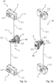
- the locking device 10 essentially consists of three elements, namely two locking latches 1 and an actuating element 3 arranged between the two locking latches 1.
- the actuating element 3 is coupled to one of the two locking latches 1 via a coupling device 2 and can be rotated back and forth by hand about an actuating axis of rotation between a locking position VB and an unlocking position VE via an actuating handle 3.5.
- the locking slides 1.1 of the locking latches 1 can be moved back and forth in a linear direction between a locking position V and an unlocking position E. If the actuating element 3 is in the locking position VB, the locking slides 1.1 of the locking latches 1 are also in the locking position V.
- the locking slides 1.1 are connected to the Fig. 1d and 1e shown spring 4 is pre-tensioned in its locking position V, so that an active movement of the locking slide 1.1 into the locking position V via the actuating element 3 is not necessary. Rather, the coupling between the locking latches 1 and the actuating element 3 ensures that the actuating element 3 is also pre-tensioned into the locking position VB via the springs 4.
- the locking slides 1.1 of the locking latches 1 are now in the open position without any further force due to the spring preload initially in the locking position V, which means that they protrude laterally from the door.
- the actuating element 3 is also in the locking position VB.
- the locking slides 1.1 When the door is now closed, the locking slides 1.1, which are still in the locking position V, come into contact with the door frame. At their outer ends, the locking slides 1.1 are equipped with a locking area 1.12 designed like a ramp, which can be clearly seen in the illustration in 1a, for example. When this locking area 1.12 comes into contact with the frame, it ensures that the locking slides 1.1 are automatically moved against the force of the spring 4 in the direction of the unlocking position E when the door is closed via the fixed frame. Due to the movement of the locking slides 1.1, the actuating element 3 is also rotated from the locking position VB to the unlocking position EB.
- the locking slides 1.1 As soon as the door is closed far enough that the locking slides 1.1 have passed the frame, they automatically engage behind the door frame in the locking position V due to the pre-tensioning force of the springs 4.
- the locking slides 1.1 or the locking latches 1 connected to the door then ensure that the door can no longer be opened due to this rear engagement. Due to the spring pre-tensioning force, it is not necessary to actively move the locking slides 1.1 into the locking position V; it is basically sufficient if the door is slammed or slammed shut with a certain force so that the locking slides 1.1 are moved through the frame against the force of the spring 4.
- the locking slides 1.1 When the locking slides 1.1 are spring-drivenly transferred from the unlocking position E back to the locking position V, the actuating element 3 then automatically rotates back to the locking position VB.
- the locking slides 1.1 In order to open the door again, the locking slides 1.1 must first be moved back into the unlocking position E against the force of the spring 4, in which they no longer grip the door frame.
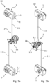
- the actuating handle 3.5 of the actuating element 3 can be moved as shown in the Fig. 1c and 2c anti-clockwise. This rotary movement is passed on via the two coupling devices 2 to the two locking latches 1 or to the corresponding locking slides 1.1 and results in the locking slides 1.1 being retracted in the same direction.
- the locking slides 1.1 have reached the unlocking position E and the door can then be opened, with the locking slides 1.1 being guided past the door frame.
- the actuating element 3 or the actuating handle 3.5 can be released again and due to the springs 4 the locking slides 1.1 spring back to the locking position V and the actuating element 3 back to the locking position VB.
- the actuating element 3 or the actuating handle 3.5 has a locking device 3.4 in the manner of a locking cylinder.
- This locking device 3.4 can prevent the actuating handle 3.5 from moving from the locking position VB to the unlocking position VE, so that the door can be secured in its closed position against unwanted or unauthorized unlocking and opening via the locking device 3.4. Due to the forced coupling between the actuating element 3 and the locking slides 1.1, which is described in more detail below, the locking device 3.4 can also prevent the locking slides 1.1 from moving.
- the actuating element 3 also has a locking indicator 3.2.
- This locking indicator 3.2 has an indicator surface that is only visible when the actuating element 3 is in the unlocking position EB, in order to signal that the locking slides 1.1 of the locking latches 1 are then also in the unlocking position E and the door is not locked.
- the indicator surface 3.2 has a signal color. If the signal color is therefore visible, the actuating element 3 and thus also the locking latches 1 are not in the locking position V, VB.
- the two locking slides 1.1 are first moved in the manner described above through the door frame from the extended locking position V in the direction of the retracted unlocking position E. Due to the movement coupling between the locking latches 1 or the locking slides 1.1 and the actuating element 3, the actuating handle 3.5 then also moves so that the indicator surface 3.2 becomes visible and it is evident that the locking slides 1.1 of the locking latches 1 are in the unlocking position E.
- the actuating element 3 is also rotated back into the locking position VB by the pre-tensioning force of the springs 4, so that the indicator surface is no longer visible. Since the two locking latches 1 are bidirectionally coupled to the actuating element 3, the locking latches 1 are also bidirectionally coupled to one another. A movement of the locking slide 1.1 of a locking latch 1 therefore automatically leads to a movement of the other locking slides 1.1. It is therefore not possible to move the locking slides 1.1 or the actuating element 3 independently of one another.
- the locking indicator 3.2 signals that the locking slides 1.1 are not properly locked. However, by pushing the door further in the area of the latch 1 of the not yet correctly positioned latch slide 1.1, this latch slide 1.1 can then also reach behind the frame. Due to the pre-tension of the spring 4, all latch slides 1.1 then move in the same direction into the locking position V.
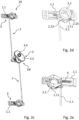
- the locking latches 1 have a box-shaped locking housing 1.2 in which the locking slide 1.1 is mounted so as to be movable in a linear direction.
- the control housings 1.2 have a lateral opening which can be used, for example, in the Fig. 3b can be clearly seen, and from which the end of the locking slide 1.1 having the locking area 1.12 protrudes in the locking position V.
- the spring 4 is connected on one side to the locking slide 1.1 and on the other side to the locking housing 1.2 so that the locking slide 1.1 can be moved relative to the locking housing 1.2 under the action of the spring 4.
- the locking slides 1.1 are of elongated geometry overall and have a driver 1.11 in the lower area, which interacts with the coupling device 2 in order to ensure a movement coupling between the locking slide 1.1 and the actuating element 3 in both directions.
- the coupling device 2 essentially consists of an elongated coupling rod 2.1 and a coupling element 2.2 arranged at the latch side end of the coupling rod 2.1, which is designed as a coupling ring.
- the coupling element 2.2 is mounted in the latch housing 1.2 so as to be rotatable about an axis of rotation which extends in the normal direction to the door plane.
- the latch housing 1.2 has a bearing projection 1.21 designed in the manner of a projecting pin, which in the illustration of the Fig. 3b can be seen.
- the coupling element 2.2 Due to the rotatable mounting of the coupling element 2.2 in the locking housing 1.2, this can be rotated back and forth around the axis of rotation by a substantially vertical movement of the coupling rod 2.1.
- the coupling element 2.2 has a linkage eyelet 2.21, which in the illustration of the Fig. 3a and 3b can be seen and into which the coupling rod 2.1 can pivotally engage.
- Two linkage eyes 2.21 are provided so that the coupling element 2.2 can also be used in other installation situations or in order to couple the coupling element 2.2 with another coupling rod 2.1 with another coupling element 2.2, although in the embodiment shown only one of the two linkage eyes 2.21 is used.
- the coupling element 2.2 has two coupling projections 2.22, 2.23 projecting in the axial direction, which are shown, for example, in the illustration of the Fig. 3b to can be seen and between which the driver 1.11 of the locking slide 1.1 is arranged.
- the driver 1.11 is coupled to the two coupling projections 2.22, 2.23 in such a way that a rotary movement of the coupling element 2.2 is converted into a linear movement of the locking slide 1.1.
- a linear movement of the locking slide 1.1 entails a rotary movement of the coupling element 2.2.
- a bidirectional movement coupling of the elements is thus made possible via the two coupling projections 2.22, 2.23 and the driver 1.11.
- This movement causes the coupling element 2.2 to rotate as shown in the Fig.2 counterclockwise and the coupling projection 2.22 presses the driver 1.11 and thus the locking slide 1.1 from the locking position V towards the unlocking position E.
- the locking slide 1.1 or its locking area 1.12 protruding from the locking housing 1.2 is thus at least partially retracted into the locking housing 1.2.
- This retracted unlocking position E is shown in the illustration of the Fig. 2a to recognize.
- the movement of the actuating element 3 via the locking slides 1.1 now works in the same way. If the locking slides 1.1 are in the locking position V and the door is closed, the locking slides 1.1 are moved towards the unlocking position E by contact with the door frame.
- the driver 1.11 with the other coupling projection 2.23 which causes a rotation of the coupling element 2.2 in the locking housing 1.2. This rotation pushes the coupling rod 2.1 in the direction of the actuating element 3 and the actuating handle 3.5 is accordingly moved from the locking position VB to the unlocking position EB, so that the indicator surface also becomes visible.
- the locking slides 1.1 When the locking slides 1.1 then reach behind the door frame, they jump from the corresponding unlocking position E into the locking position V due to the pre-tensioning force of the spring 4.
- the driver 1.11 presses the coupling projection 2.22 outwards and the coupling element 2.2 rotates in the opposite direction. Accordingly, the coupling rods 2.1 are subjected to a tensile force and pulled away from the actuating element 3.
- the actuating handle 3.5 is then also rotated back into the locking position VB so that the indicator surface is no longer visible.
- the actuating element 3 or the actuating handle 3.5 rotates from the locking position VB to the unlocking position VB and then automatically back to the locking position VB due to the pre-tensioning force of the spring 4. This happens very quickly, especially when the door is slammed shut quickly.
- Both coupling projections 2.22, 2.23 are designed to project in the axial direction relative to the contour of the coupling element 2.2, so that the driver 1.11 can be arranged between the two coupling projections 2.22, 2.23.
- the driver 1.11 has two surfaces, so that when the locking slide 1.1 moves in the direction of the locking position V, one surface is in contact with the first coupling projection 2.22 and when the opposite movement the second surface comes into contact with the second coupling projection 2.23.
- the first outer coupling projection 2.22 which faces the locking area 1.12 of the locking slide 1.1, is designed as a coupling nose.
- the inner coupling projection 2.23 which faces away from the locking area 1.12 of the locking slide 1.1, has a somewhat more complex geometry, as can also be seen from the illustration of the Fig. 3b can be seen.
- the second coupling projection 2.23 is designed as a guide hook and protrudes in the radial direction from the annular contour of the coupling element 2.2. This projection is also shown in the illustration of the Fig. 3a can be clearly seen.
- the actuating element 3 has a connection point 3.1 for connection to the respective coupling rods 2.1, which is located on the inside the door. These connection points 3.1 can be rotated about the actuating axis by means of an actuating shaft 3.3 extending through the door with the actuating handle 3.5 which can be rotated by hand about the actuating axis from the outside of the door.
- the coupling rods 2.1 are pivotally coupled to the actuating element 3 via the connection points 3.1, so that the coupling rods 2.1 can be moved up or down via a rotational movement of the actuating element 3 or the connection points 3.1.
- the connection points 3.1 of the actuating element 3 and the linkage eyes 2.21 move or rotate largely in the same direction as one another.
- the latch bolts 1 or the latch slides 1.1 of the latch bolts 1 can also be operated from the inside of the door or from the inside of the caravan or mobile home.
- the latch bolts 1 are equipped with an additional actuation 1.3, which is designed in the manner of a rotary handle and which, for example, in the illustration of the Fig. 1a can be seen.
- the respective locking slide 1.1 can be moved back and forth between the locking position V and the unlocking position E via the actuation 1.3. Due to the forced coupling of the locking slide 1.1 with the actuating element 3 and also with the other locking slides 1.1, all locking slides 1.1 can be moved via an actuation 1.3.
Landscapes
- Engineering & Computer Science (AREA)
- Mechanical Engineering (AREA)
- Structural Engineering (AREA)
- Lock And Its Accessories (AREA)
Applications Claiming Priority (1)
| Application Number | Priority Date | Filing Date | Title |
|---|---|---|---|
| DE102023101547.8A DE102023101547A1 (de) | 2023-01-23 | 2023-01-23 | Verschlussvorrichtung |
Publications (1)
| Publication Number | Publication Date |
|---|---|
| EP4403731A1 true EP4403731A1 (fr) | 2024-07-24 |
Family
ID=89663145
Family Applications (1)
| Application Number | Title | Priority Date | Filing Date |
|---|---|---|---|
| EP24153021.1A Pending EP4403731A1 (fr) | 2023-01-23 | 2024-01-22 | Dispositif de fermeture |
Country Status (2)
| Country | Link |
|---|---|
| EP (1) | EP4403731A1 (fr) |
| DE (1) | DE102023101547A1 (fr) |
Citations (4)
| Publication number | Priority date | Publication date | Assignee | Title |
|---|---|---|---|---|
| US4040652A (en) * | 1972-03-20 | 1977-08-09 | Daempa A/S | Door lock |
| DE68921843T2 (de) * | 1988-11-02 | 1995-08-03 | Thetford Corp | Freizeitfahrzeugtüraufbau. |
| WO2009049658A1 (fr) * | 2007-10-17 | 2009-04-23 | Dieter Ramsauer | Fermeture à tringle à entraînement de tringle en forme de levier |
| US20150121765A1 (en) * | 2006-09-14 | 2015-05-07 | Milgard Manufacturing Incorporated | Direct action window lock |
Family Cites Families (11)
| Publication number | Priority date | Publication date | Assignee | Title |
|---|---|---|---|---|
| US4387917A (en) * | 1979-12-26 | 1983-06-14 | Peter George Legg | Panic bolt units |
| JPH0667742U (ja) * | 1993-03-01 | 1994-09-22 | タキゲン製造株式会社 | 埋め込みハンドル装置 |
| FR2822877B1 (fr) * | 2001-03-29 | 2004-01-16 | Schneider Electric Ind Sa | Dispositif de fermeture pour coffret |
| US6758503B2 (en) * | 2001-12-19 | 2004-07-06 | Randall C. Hansen | Paddle lock having slim profile |
| DE20219446U1 (de) * | 2002-12-16 | 2003-03-20 | Möllenkamp, Brunhilde, 42549 Velbert | Betätigungsvorrichtung für Verschlüsse |
| DE102005051447A1 (de) * | 2005-01-07 | 2006-07-20 | Moellmann Industriebeschläge Gustav Moellmann GmbH & Co. KG | Verriegelung für Türen in Fahrzeugen |
| DE102016115923A1 (de) * | 2016-08-26 | 2018-03-01 | Emka Beschlagteile Gmbh & Co. Kg | Verschlussvorrichtung mit einer Betätigungsvorrichtung für eine Tür |
| DE102018120620A1 (de) * | 2018-08-23 | 2020-02-27 | Emka Beschlagteile Gmbh & Co. Kg | Verschlussvorrichtung für eine Tür |
| DE102018124159A1 (de) * | 2018-10-01 | 2020-04-02 | Hymer-Leichtmetallbau Gmbh & Co. Kg. | Flächenbündiger Betätigungsgriff für eine Schließvorrichtung |
| DE102019129440A1 (de) * | 2019-10-31 | 2021-05-06 | Emka Beschlagteile Gmbh & Co. Kg | Vorreiber zum Verriegeln einer Tür |
| DE102020120000A1 (de) * | 2020-07-29 | 2022-02-03 | Emka Beschlagteile Gmbh & Co. Kg. | Verriegelungssystem |
-
2023
- 2023-01-23 DE DE102023101547.8A patent/DE102023101547A1/de active Pending
-
2024
- 2024-01-22 EP EP24153021.1A patent/EP4403731A1/fr active Pending
Patent Citations (4)
| Publication number | Priority date | Publication date | Assignee | Title |
|---|---|---|---|---|
| US4040652A (en) * | 1972-03-20 | 1977-08-09 | Daempa A/S | Door lock |
| DE68921843T2 (de) * | 1988-11-02 | 1995-08-03 | Thetford Corp | Freizeitfahrzeugtüraufbau. |
| US20150121765A1 (en) * | 2006-09-14 | 2015-05-07 | Milgard Manufacturing Incorporated | Direct action window lock |
| WO2009049658A1 (fr) * | 2007-10-17 | 2009-04-23 | Dieter Ramsauer | Fermeture à tringle à entraînement de tringle en forme de levier |
Also Published As
| Publication number | Publication date |
|---|---|
| DE102023101547A1 (de) | 2024-07-25 |
Similar Documents
| Publication | Publication Date | Title |
|---|---|---|
| DE102017129427B3 (de) | Scharnierverschluss | |
| DE102012111085B4 (de) | Türöffner | |
| EP2803796A2 (fr) | Serrure de véhicule automobile | |
| EP2291571A1 (fr) | Dispositif de fermeture comprenant un ressort à cliquet | |
| DE102021102105A1 (de) | Kraftfahrzeugschloss | |
| DE102017209376A1 (de) | Fahrzeugverschluss-Verriegelungsanordnung mit Doppelklinken-Verriegelungsmechanismus | |
| EP2146032B1 (fr) | Dispositif destiné à ouvrir et/ou fermer ainsi qu'à verrouiller un état fermé d'un dispositif de fermeture destiné à fermer une ouverture de salle ainsi que dispositif de fermeture doté d'un tel dispositif | |
| EP3269904B1 (fr) | Système de couplage pour un verrou | |
| WO2021083456A1 (fr) | Serrure à battants pour le verrouillage d'une porte | |
| EP3665349A1 (fr) | Serrure de porte | |
| DE60114431T2 (de) | Türriegel mit hakenbolzen | |
| EP3921495B1 (fr) | Dispositif de transmission d'actionnement pour un élément levant et coulissant avec levier d'arrêt et élément levant et coulissant avec un tel dispositif | |
| EP3450659B1 (fr) | Dispositif de fermeture | |
| EP4403731A1 (fr) | Dispositif de fermeture | |
| DE4407912C2 (de) | Elektromechanisches Schloß | |
| EP3371397B1 (fr) | Ensemble ferrure | |
| DE3907632A1 (de) | Schloss mit sicherungseinrichtung, insbesondere fuer fahrzeugtueren | |
| DE102018117163A1 (de) | Vorreiber | |
| EP1683936A1 (fr) | Serrure avec pêne demi-tour et entraînement pour le pêne demi-tour | |
| EP2199729A2 (fr) | Couvercle de trou d'homme pivotant, en particulier pour véhicules militaires | |
| EP3385483B1 (fr) | Dispositif de verrouillage pour un véhicule | |
| DE10359144B4 (de) | Vorrichtung zur gemeinsamen elektromechanischen Steuerung mehrerer technischer Einrichtungen | |
| DE102024203222B3 (de) | Beschlaganordnung für ein Fenster, eine Tür oder dergleichen zur Betätigung einer Feststellbremse | |
| DE69502206T3 (de) | Verriegelbares, mechanisches Schloss | |
| DE102019102441A1 (de) | Vorreiber zum Verriegeln einer Tür |
Legal Events
| Date | Code | Title | Description |
|---|---|---|---|
| PUAI | Public reference made under article 153(3) epc to a published international application that has entered the european phase |
Free format text: ORIGINAL CODE: 0009012 |
|
| STAA | Information on the status of an ep patent application or granted ep patent |
Free format text: STATUS: THE APPLICATION HAS BEEN PUBLISHED |
|
| AK | Designated contracting states |
Kind code of ref document: A1 Designated state(s): AL AT BE BG CH CY CZ DE DK EE ES FI FR GB GR HR HU IE IS IT LI LT LU LV MC ME MK MT NL NO PL PT RO RS SE SI SK SM TR |
|
| STAA | Information on the status of an ep patent application or granted ep patent |
Free format text: STATUS: REQUEST FOR EXAMINATION WAS MADE |
|
| 17P | Request for examination filed |
Effective date: 20250124 |
|
| GRAP | Despatch of communication of intention to grant a patent |
Free format text: ORIGINAL CODE: EPIDOSNIGR1 |
|
| STAA | Information on the status of an ep patent application or granted ep patent |
Free format text: STATUS: GRANT OF PATENT IS INTENDED |