EP4403731A1 - Locking device - Google Patents
Locking device Download PDFInfo
- Publication number
- EP4403731A1 EP4403731A1 EP24153021.1A EP24153021A EP4403731A1 EP 4403731 A1 EP4403731 A1 EP 4403731A1 EP 24153021 A EP24153021 A EP 24153021A EP 4403731 A1 EP4403731 A1 EP 4403731A1
- Authority
- EP
- European Patent Office
- Prior art keywords
- locking
- coupling
- actuating element
- door
- slide
- Prior art date
- Legal status (The legal status is an assumption and is not a legal conclusion. Google has not performed a legal analysis and makes no representation as to the accuracy of the status listed.)
- Pending
Links
Images


Classifications
-
- E—FIXED CONSTRUCTIONS
- E05—LOCKS; KEYS; WINDOW OR DOOR FITTINGS; SAFES
- E05B—LOCKS; ACCESSORIES THEREFOR; HANDCUFFS
- E05B41/00—Locks with visible indication as to whether the lock is locked or unlocked
-
- E—FIXED CONSTRUCTIONS
- E05—LOCKS; KEYS; WINDOW OR DOOR FITTINGS; SAFES
- E05B—LOCKS; ACCESSORIES THEREFOR; HANDCUFFS
- E05B63/00—Locks or fastenings with special structural characteristics
- E05B63/14—Arrangement of several locks or locks with several bolts, e.g. arranged one behind the other
- E05B63/143—Arrangement of several locks, e.g. in parallel or series, on one or more wings
-
- E—FIXED CONSTRUCTIONS
- E05—LOCKS; KEYS; WINDOW OR DOOR FITTINGS; SAFES
- E05B—LOCKS; ACCESSORIES THEREFOR; HANDCUFFS
- E05B83/00—Vehicle locks specially adapted for particular types of wing or vehicle
- E05B83/16—Locks for luggage compartments, car boot lids or car bonnets
- E05B83/22—Locks for luggage compartments, car boot lids or car bonnets for luggage compartments at the side of the vehicle, e.g. of buses or camper vans
-
- E—FIXED CONSTRUCTIONS
- E05—LOCKS; KEYS; WINDOW OR DOOR FITTINGS; SAFES
- E05B—LOCKS; ACCESSORIES THEREFOR; HANDCUFFS
- E05B83/00—Vehicle locks specially adapted for particular types of wing or vehicle
- E05B83/36—Locks for passenger or like doors
- E05B83/44—Locks for passenger or like doors for recreational vehicles, e.g. caravans or camper vans
-
- E—FIXED CONSTRUCTIONS
- E05—LOCKS; KEYS; WINDOW OR DOOR FITTINGS; SAFES
- E05C—BOLTS OR FASTENING DEVICES FOR WINGS, SPECIALLY FOR DOORS OR WINDOWS
- E05C9/00—Arrangements of simultaneously actuated bolts or other securing devices at well-separated positions on the same wing
- E05C9/002—Arrangements of simultaneously actuated bolts or other securing devices at well-separated positions on the same wing with arrangements allowing the wing to be slam-shut, e.g. by securing elements with latching action
-
- E—FIXED CONSTRUCTIONS
- E05—LOCKS; KEYS; WINDOW OR DOOR FITTINGS; SAFES
- E05C—BOLTS OR FASTENING DEVICES FOR WINGS, SPECIALLY FOR DOORS OR WINDOWS
- E05C9/00—Arrangements of simultaneously actuated bolts or other securing devices at well-separated positions on the same wing
- E05C9/04—Arrangements of simultaneously actuated bolts or other securing devices at well-separated positions on the same wing with two sliding bars moved in opposite directions when fastening or unfastening
- E05C9/043—Arrangements of simultaneously actuated bolts or other securing devices at well-separated positions on the same wing with two sliding bars moved in opposite directions when fastening or unfastening with crank pins and connecting rods
Definitions
- the invention relates to a locking device for locking a door, in particular a door of a caravan or mobile home, against a door frame with at least two locking latches, each of which has a locking slide that is pre-tensioned by a spring in the direction of a locking position and automatically locks, and with an actuating element that is coupled to the locking slides for unlocking the locking latches.
- Corresponding locking devices can be used in various areas of technology.
- One possible area of application is the doors of a caravan or mobile home. These doors usually have to be secured to a door frame at several locking points. locked to ensure that the sometimes large doors are reliably locked and that the seal arranged between the door and the door frame can be reliably compressed.
- corresponding locking devices often also have several latches which are arranged one below the other on the inside of the door in the area of the door edge opposite the door hinges so that the door can be reliably locked to the door frame over its entire height.
- at least two latches are used, with one arranged in the upper area and the other in the lower area of the door.
- a door does not necessarily have to be a door in the true sense of the word; flaps, in particular storage flaps, hatches, covers or windows are also included under the term door.
- the locking latches each have a locking slider that can be moved, in particular in a linear direction, back and forth between a locking position and an unlocking position.
- the locking slider In the locking position, the locking slider can reach behind the frame of the door and thus fix the door in place relative to the door frame.
- the unlocking position the locking sliders are retracted so that they no longer reach behind the frame of the door and the door can therefore be opened. It is also known to pre-tension the locking sliders of the locking latches into the locking position, for which each locking latch can be equipped with a spring.
- the locking device thus enables the door to be locked automatically and it is sufficient to close the door or slam it shut with a certain amount of force depending on the pre-tensioning force of the spring. Active operation of the latches or locking slides is not necessary for this.
- the invention has the object of specifying a locking device with which a reliable locking of the door can be ensured.
- actuating element has a locking indicator and the locking latches are each mechanically coupled to the actuating element by means of the locking indicator to indicate correct locking of the locking slides.
- the locking indicator makes it very easy to see whether all latches are in the locking position and, accordingly, whether all locking slides are reliably engaging behind the door frame to lock the door. In this respect, it can be determined at a glance whether the door needs to be pushed in again or whether the door is already reliably locked at all locking points.
- the coupling between the actuating element and the locking latches or the locking slides is therefore bidirectional in nature. This means that it is not only possible to move the locking slides into the unlocking position via the actuating element, but that a movement of the locking slides also leads to a movement of the actuating element.
- the locking slides are moved by the door frame against the force of the spring in the direction of the unlocking position and thus also the actuating element. This The movement of the locking slides in the direction of the unlocking position can thus be recognized on the actuating element.
- the actuating element also moves accordingly. Due to the bidirectional coupling of the latches or the locking slides and the actuating element, the position of the locking slides can be determined directly from the position of the actuating element and it can be seen at a glance whether the door is reliably locked or not.
- the actuating element is bidirectionally coupled to the or all of the locking slides. Such coupling does not make it possible to move the locking slides independently of the actuating element. Rather, the actuating element can be coupled to the locking slides both in the direction of the locking position and in the direction of the unlocking position. Since when the door is closed, the locking slides are first pressed by the frame in the direction of the unlocking position and then spring back towards the locking position by the spring, both movements also lead to a movement of the actuating element and it is not possible to move the locking slides or the actuating element independently of one another. The actuating element and the locking slides can therefore be forcibly coupled to one another. Minor relative movements, e.g. due to tolerances or a certain amount of play between the components, are of course possible.
- the actuating element can also be moved back and forth between a locking position and an unlocking position, in particular rotated back and forth.
- the coupling between the actuating element and the locking latches or locking slides allows the locking element to be moved back and forth between a locking position and an unlocking position.
- a movement of the actuating element leads directly to a corresponding movement of the locking slide, and a movement of the locking slide leads to a corresponding movement of the actuating element.
- an intuitive unlocking of the locking latches can be achieved in the manner of a latch or knob operation.
- it can have an actuating handle, via which the actuating element can be moved by hand, in particular rotated back and forth by hand.
- the actuating element is pre-tensioned into the locking position via the springs of the locking latches. Due to the forced coupling of the locking latches or the locking slide with the actuating element, the actuating element can be pre-tensioned into the locking position via the springs of the locking slides. If the actuating element is thus moved manually from the locking position to the unlocking position, it can automatically spring back into the locking position after being released. It is therefore not necessary for the actuating element itself to be pre-tensioned via its own pre-tensioning element or spring.
- the locking indicator has an indicator surface that is only visible in the unlocking position.
- the indicator surface can provide visual feedback on the position of the actuating element and thus also on the locking status of the latches.
- the indicator surface can be visible when at least one latch slide is not in the locking position, so that the indicator surface can be used to directly detect when the door is not locked or not yet correctly locked.
- the indicator surface can have a signal color so that an incorrect The locking state cannot be overlooked.
- the locking indicator can have a fixed section and a section that can be rotated relative to it, whereby the rotatable section can be rotated using the operating handle.
- the indicator surface can be part of the fixed section so that it can be released when the rotatable section is rotated into the unlocking position and can thus be recognized.
- the indicator surface In the locking position, the indicator surface can be covered by the rotatable section.
- the rotatable section or the operating handle can have an asymmetrical geometry.
- the indicator surface can be arranged on a ring that is only visible in the unlocked position. For example, the ring can protrude outwards in the unlocking position so that a shell surface designed as an indicator surface becomes visible.
- the actuating element has a locking device, in particular a locking device in the manner of a locking cylinder.
- the locking device can prevent movement of the actuating element and, due to the forced coupling, also movement of the locking slide. In order to move the actuating element, it is therefore necessary to first ensure that movement is not blocked by the locking device.
- the locking device can be locked or unlocked using a suitable key.
- the locking device can be integrated in the actuating handle and can therefore be accessible from the outside.
- the actuating shaft can extend through the door and thus movements, in particular rotary movements, on the outside of the door can be transmitted via the shaft to the inside of the door or to the inside of the door.
- the actuating shaft can therefore be rotationally coupled to the actuating handle.
- connection points for connecting one locking latch each.
- a rotation can be passed on via the actuating shaft to the connection points, which can also rotate around the axis of rotation of the actuating shaft.
- the connection points can be rotationally coupled to the actuating handle via the actuating shaft.
- the locking latches are coupled to one another via the actuating element.
- the locking slides of the locking latches move in parallel with one another and there is no relative movement.
- the actuating element of one locking latch it is not possible for the actuating element of one locking latch to be transferred to the locking position if another locking latch is still in the unlocking position.
- a locking slide in the unlocking position which, for example, has not completely gripped behind the door frame and is therefore pressed in by the door frame, instead locks the other locking slide(s) and prevents them from being automatically transferred to the locking position by the spring and locking behind the frame.
- the locking latches are each coupled with the actuating element via a coupling device.
- the movement of the actuating element or the actuating handle, the actuating shaft and the connection points can be transmitted to the locking slides via the coupling device.
- the A coupling device can also transmit a movement in the opposite direction, i.e. from the locking slides to the connection points and via the actuating shaft to the actuating handle.
- Each locking latch can be assigned a coupling device so that the number of locking latches and the number of coupling devices can match. This enables a reliable movement coupling between the various locking slides and the common actuating element to be achieved.
- the actuating element is directly coupled to a latch via a coupling device.
- the coupling device is coupled at one end to the actuating element and at the other end to the latch.
- the actuating element can also be possible for the actuating element to be indirectly coupled to a latch. This can be the case if the actuating element is directly coupled to a latch and this latch is then coupled to another latch via a further coupling device.
- the latches can therefore also be connected in series and it is not absolutely necessary for all latches to be directly coupled to the actuating element.
- Such a configuration is advantageous in particular if more than two latches are provided. This can be the case in particular with very high doors.
- the locking slides of all locking latches can move in the same direction and therefore without any significant relative movement, regardless of whether the locking latch is coupled directly or indirectly to the actuating element.
- the coupling device is designed as a rod coupling.
- This design allows the distance between the latches and the actuator to be comparatively large, which With regard to the arrangement of the latches and the operating element, there is a correspondingly large design leeway.
- the operating element can be arranged on the door, for example at a medium height, and two latches can be provided, which can be arranged at the same distance from the operating element above and below the operating element. A large distance between the latches ensures that the door is reliably locked over its entire height.
- a rod coupling has proven to be reliable and robust in practice, which is particularly advantageous in the area of mobile home and caravan doors.
- the coupling device has a coupling rod.
- the coupling rod can be coupled on one side to the actuating element, in particular to a connection point, and on the other side to the locking slide. There can be a separate connection point for each coupling rod or for each coupling device. In the case of two coupling devices, the two connection points of the actuating element can be opposite one another with regard to the axis of rotation.
- the coupling rod can be pivotally articulated to the connection points so that the coupling rods can move in the longitudinal direction of the rod, for example up or down, when the actuating element rotates.
- the coupling rods can extend essentially in the vertical direction or in the direction of the main extension direction of the door. The primarily linear movement of the coupling rod can be diverted in the area of the locking slide into a linear vertical movement of the locking slide.
- the coupling rod can be provided on both sides with a The locking slides must be coupled so that the movement of one locking slide can be transferred to the other locking slide.
- the latch it has proven to be advantageous if it has a latch housing in which the latch slide is guided.
- the latch housing can serve as a linear guide and ensure that the latch slide can be reliably moved back and forth between the locking position and the unlocking position.
- the latch housing can have a side opening so that the latch slide can protrude from the latch housing at least with its locking area that engages behind the frame.
- the latch housing can have a recess so that the coupling device or the coupling rod can extend into the interior of the latch housing and move the latch slide.
- several recesses can also be provided so that the coupling rod can be connected to different linkage eyes. This is particularly advantageous in the case of a series connection or an indirect coupling.
- the latch housing can have a box-shaped geometry and be arranged on the inside of the door. Alternatively, it is also possible for the latch housing to be located inside the door and thus integrated into the door.
- the latch bolt has an actuation for moving the latch slide.
- the actuation can represent an alternative actuation or movement option for the latch slide, so that it can be moved not only via the actuation element.
- the latch slide can also be actuated from the inside of the door or from inside the caravan or mobile home via the actuation.
- the actuation can have a rotary handle, via which a coupling element described in more detail below can be rotated, which can be used for linear movement with the By coupling a locking slide with the other locking slides or with the actuating element, all locking slides and also the actuating element can be moved accordingly via the actuation.
- the locking slide can have a locking area that can engage behind the door frame in the locking position.
- This locking area can be equipped with a starting bevel so that the locking slide can move independently when the door is closed and the door frame is contacted and can be moved against the force of the spring in the direction of the unlocking position. In this respect, it is not necessary to manually move the locking slide into the unlocking position to close and lock the door. Instead, when the door is closed, the locking slide is automatically moved into the unlocking position by the starting bevel.
- the actuating element or the actuating handle visible from the outside can rotate accordingly.
- the coupling device has a coupling element which is coupled to the coupling rod and to the locking slide. Via the coupling element, a linear movement of the coupling rod, in particular a movement in the horizontal direction, can be converted into a linear movement of the locking slide, in particular a movement in the vertical direction. Furthermore, the coupling element can ensure not only a movement of the actuating element onto the locking slide, but also a movement in the opposite direction, namely from the locking slide via the coupling element and the coupling rod onto the actuating element.
- the locking slide is coupled to the coupling element in such a way that it can be moved in a linear direction via a rotary movement of the coupling element.
- the coupling element can therefore be rotatable. Accordingly, a linear movement of the locking slide can lead to a rotary movement of the coupling element, which in turn can then be redirected into a linear movement of the coupling rod.
- the coupling element it has proven advantageous if it has two coupling projections and if the locking slide has a driver arranged between the two coupling projections.
- the locking slide and the coupling device or the coupling element can be coupled to one another in terms of movement via the two coupling projections and the driver.
- the coupling projections can extend in the axial direction and be designed to project in the direction of the locking slide.
- the driver can be moved by one of the two coupling projections into the locking position or into the unlocking position, depending on the direction of rotation of the actuating element or the actuating handle.
- the locking slide itself is moved, for example by contact with the door frame when the door is closed, the locking slide can rotate the coupling element via the driver and via contact between the driver and one of the two coupling projections and thereby also move the actuating element into the respective position.
- the driver can come into contact with one of the two coupling projections and, when moving in the direction of the locking position, with the other coupling projection.
- the first coupling projection is designed as an axially Direction projecting coupling lug.
- the second coupling projection can be designed as a sickle-shaped guide hook in particular.
- the driver can come into contact with the second coupling projection and thereby rotate the coupling element.
- the driver can come into contact with the first coupling projection and thereby rotate the coupling element in the opposite direction.
- the design as a guide hook ensures that the driver can slide on or at the corresponding coupling projection during a linear movement, which leads to a uniform and low-impact rotation of the coupling element.
- the coupling element if it is designed as a coupling ring.
- the coupling ring design enables easy back and forth rotation around the axis of rotation.
- the guide hook protrudes in the radial direction from the coupling element or from the contour of the coupling ring. This also leads to a uniform rotation of the coupling element and to the driver sliding on the coupling projection. It is advantageous if the guide hook protrudes outwards from the coupling ring or from the contour of the coupling ring, which enables a comparatively large angle of rotation. It is advantageous if the coupling ring has to be rotated by approximately 45 degrees in order to move the locking slide back and forth between the locking position and the unlocking position.
- the corresponding coupling projection or guide hook can be designed in such a way that it prevents movement of the locking slide in at least one direction in the unlocked position. It is therefore not possible to move the locking slide beyond the unlocked position, but movement beyond the unlocked position can be prevented by the guide hook. From the unlocked position, the locking slide can therefore only be moved back towards the locking position.
- the latter can have a linkage eyelet.
- the linkage eyelet can be designed to protrude in the radial direction and thus have a comparatively large distance from the axis of rotation extending centrally through the coupling ring. This means that the coupling ring can be reliably rotated back and forth during a linear movement of the coupling rod.
- the coupling rod can be rotatably connected to the linkage eyelet.
- the coupling rod is hooked into the linkage eyelet at one end. It has also proven advantageous if several, in particular two, linkage eyes are provided. Two linkage eyes can be opposite one another with regard to the axis of rotation and thus also be arranged on opposite sides of the coupling element.
- the multiple linkage eyes also make it possible to couple the corresponding latch not only to the actuating element via a coupling device, but also to another latch slide via another coupling device.
- one linkage eye can be connected to the actuating element via a coupling rod and the other linkage eye can be connected to the coupling element or the linkage eye of another via another coupling rod.
- the locking slides of the two locking slides can then move in the same direction and be moved back and forth together between the locking position and the unlocking position. This basically corresponds to a series connection of the two locking slides.
- the coupling element is mounted in the locking housing so that it can rotate.
- the locking housing can be fixed to the door, in particular on the inside of the door, and thus ensure reliable rotation of the coupling element or the coupling ring.
- the locking housing can have a bearing projection on which the coupling element can be mounted so that it can rotate.
- a bearing via a roller bearing can also be provided.
- the locking housing has stops to limit movement of the coupling element.
- the corresponding stops can limit movement of the coupling element in such a way that the locking slide can only move back and forth between the locking position and the unlocking position.
- the stops can also be arranged on the locking slide side so that movement of the locking slide is immediately prevented. The movement coupling between the locking slide and the coupling element then prevents further movement of the coupling element.
- the coupling of the actuating element and the latch it has proven to be advantageous if a tensile force is exerted on the coupling rod when the actuating element moves from the locking position to the unlocking position.
- the coupling rod can be pulled in the direction of the actuating element by a corresponding movement, whereby the coupling element or the coupling ring can be rotated and the latch slide can be retracted into the latch or the latch housing.
- the latch slide is retracted accordingly so that it no longer grips behind the door frame, the door can be opened.
- the latch or latches are coupled to the actuating element in such a way that when the latch slide moves from the locking position to the unlocking position, a compressive force is exerted on the coupling rod.
- the latch slide(s) can exert a compressive force on the coupling rod, so that they can basically be moved in the direction of the actuating element.
- the coupling rod or rods can therefore rotate or press the actuating element about its actuating axis into the unlocking position using a compressive force emanating from the latch slides.
- the indicator surface of the locking indicator can then be seen, so that it is clear that the latch slide(s) are in the unlocking position.
- the door can be, for example, an entrance door to the caravan or mobile home, but also a storage flap, a hatch or a window.
- the actuating element is accessible from the outside of the door and the locking latches are arranged on the inside of the door.
- the actuating shaft of the actuating element can therefore extend through the door and by actuating the actuating handle on the outside of the door, the locking latches arranged on the inside can grip behind the door frame to lock the door.
- the inside of the door does not necessarily mean the innermost surface of the door; the door can also have a panel on the inside so that the mechanics or the coupling devices are not immediately visible.
- the locking latches and the coupling device can also be arranged inside the door, depending on how thick the door is.
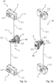
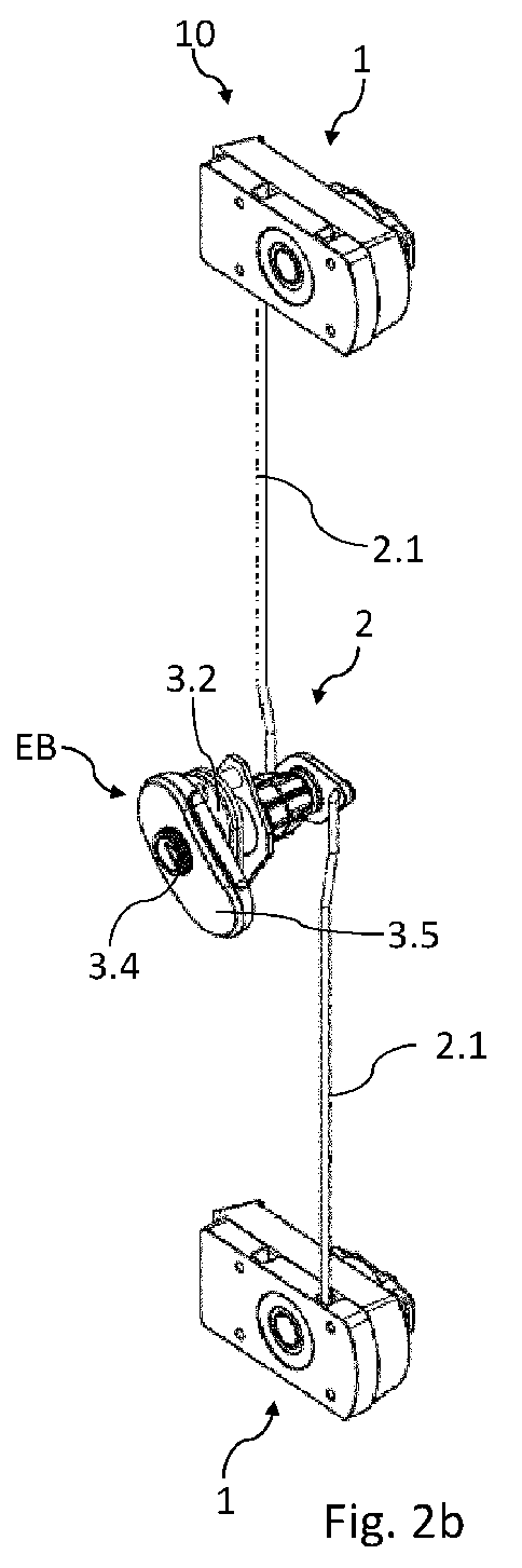
- the locking device 10 essentially consists of three elements, namely two locking latches 1 and an actuating element 3 arranged between the two locking latches 1.
- the actuating element 3 is coupled to one of the two locking latches 1 via a coupling device 2 and can be rotated back and forth by hand about an actuating axis of rotation between a locking position VB and an unlocking position VE via an actuating handle 3.5.
- the locking slides 1.1 of the locking latches 1 can be moved back and forth in a linear direction between a locking position V and an unlocking position E. If the actuating element 3 is in the locking position VB, the locking slides 1.1 of the locking latches 1 are also in the locking position V.
- the locking slides 1.1 are connected to the Fig. 1d and 1e shown spring 4 is pre-tensioned in its locking position V, so that an active movement of the locking slide 1.1 into the locking position V via the actuating element 3 is not necessary. Rather, the coupling between the locking latches 1 and the actuating element 3 ensures that the actuating element 3 is also pre-tensioned into the locking position VB via the springs 4.
- the locking slides 1.1 of the locking latches 1 are now in the open position without any further force due to the spring preload initially in the locking position V, which means that they protrude laterally from the door.
- the actuating element 3 is also in the locking position VB.
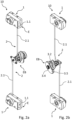
- the locking slides 1.1 When the door is now closed, the locking slides 1.1, which are still in the locking position V, come into contact with the door frame. At their outer ends, the locking slides 1.1 are equipped with a locking area 1.12 designed like a ramp, which can be clearly seen in the illustration in 1a, for example. When this locking area 1.12 comes into contact with the frame, it ensures that the locking slides 1.1 are automatically moved against the force of the spring 4 in the direction of the unlocking position E when the door is closed via the fixed frame. Due to the movement of the locking slides 1.1, the actuating element 3 is also rotated from the locking position VB to the unlocking position EB.
- the locking slides 1.1 As soon as the door is closed far enough that the locking slides 1.1 have passed the frame, they automatically engage behind the door frame in the locking position V due to the pre-tensioning force of the springs 4.
- the locking slides 1.1 or the locking latches 1 connected to the door then ensure that the door can no longer be opened due to this rear engagement. Due to the spring pre-tensioning force, it is not necessary to actively move the locking slides 1.1 into the locking position V; it is basically sufficient if the door is slammed or slammed shut with a certain force so that the locking slides 1.1 are moved through the frame against the force of the spring 4.
- the locking slides 1.1 When the locking slides 1.1 are spring-drivenly transferred from the unlocking position E back to the locking position V, the actuating element 3 then automatically rotates back to the locking position VB.
- the locking slides 1.1 In order to open the door again, the locking slides 1.1 must first be moved back into the unlocking position E against the force of the spring 4, in which they no longer grip the door frame.
- the actuating handle 3.5 of the actuating element 3 can be moved as shown in the Fig. 1c and 2c anti-clockwise. This rotary movement is passed on via the two coupling devices 2 to the two locking latches 1 or to the corresponding locking slides 1.1 and results in the locking slides 1.1 being retracted in the same direction.
- the locking slides 1.1 have reached the unlocking position E and the door can then be opened, with the locking slides 1.1 being guided past the door frame.
- the actuating element 3 or the actuating handle 3.5 can be released again and due to the springs 4 the locking slides 1.1 spring back to the locking position V and the actuating element 3 back to the locking position VB.
- the actuating element 3 or the actuating handle 3.5 has a locking device 3.4 in the manner of a locking cylinder.
- This locking device 3.4 can prevent the actuating handle 3.5 from moving from the locking position VB to the unlocking position VE, so that the door can be secured in its closed position against unwanted or unauthorized unlocking and opening via the locking device 3.4. Due to the forced coupling between the actuating element 3 and the locking slides 1.1, which is described in more detail below, the locking device 3.4 can also prevent the locking slides 1.1 from moving.
- the actuating element 3 also has a locking indicator 3.2.
- This locking indicator 3.2 has an indicator surface that is only visible when the actuating element 3 is in the unlocking position EB, in order to signal that the locking slides 1.1 of the locking latches 1 are then also in the unlocking position E and the door is not locked.
- the indicator surface 3.2 has a signal color. If the signal color is therefore visible, the actuating element 3 and thus also the locking latches 1 are not in the locking position V, VB.
- the two locking slides 1.1 are first moved in the manner described above through the door frame from the extended locking position V in the direction of the retracted unlocking position E. Due to the movement coupling between the locking latches 1 or the locking slides 1.1 and the actuating element 3, the actuating handle 3.5 then also moves so that the indicator surface 3.2 becomes visible and it is evident that the locking slides 1.1 of the locking latches 1 are in the unlocking position E.
- the actuating element 3 is also rotated back into the locking position VB by the pre-tensioning force of the springs 4, so that the indicator surface is no longer visible. Since the two locking latches 1 are bidirectionally coupled to the actuating element 3, the locking latches 1 are also bidirectionally coupled to one another. A movement of the locking slide 1.1 of a locking latch 1 therefore automatically leads to a movement of the other locking slides 1.1. It is therefore not possible to move the locking slides 1.1 or the actuating element 3 independently of one another.
- the locking indicator 3.2 signals that the locking slides 1.1 are not properly locked. However, by pushing the door further in the area of the latch 1 of the not yet correctly positioned latch slide 1.1, this latch slide 1.1 can then also reach behind the frame. Due to the pre-tension of the spring 4, all latch slides 1.1 then move in the same direction into the locking position V.
- the locking latches 1 have a box-shaped locking housing 1.2 in which the locking slide 1.1 is mounted so as to be movable in a linear direction.
- the control housings 1.2 have a lateral opening which can be used, for example, in the Fig. 3b can be clearly seen, and from which the end of the locking slide 1.1 having the locking area 1.12 protrudes in the locking position V.
- the spring 4 is connected on one side to the locking slide 1.1 and on the other side to the locking housing 1.2 so that the locking slide 1.1 can be moved relative to the locking housing 1.2 under the action of the spring 4.
- the locking slides 1.1 are of elongated geometry overall and have a driver 1.11 in the lower area, which interacts with the coupling device 2 in order to ensure a movement coupling between the locking slide 1.1 and the actuating element 3 in both directions.
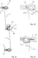
- the coupling device 2 essentially consists of an elongated coupling rod 2.1 and a coupling element 2.2 arranged at the latch side end of the coupling rod 2.1, which is designed as a coupling ring.
- the coupling element 2.2 is mounted in the latch housing 1.2 so as to be rotatable about an axis of rotation which extends in the normal direction to the door plane.
- the latch housing 1.2 has a bearing projection 1.21 designed in the manner of a projecting pin, which in the illustration of the Fig. 3b can be seen.
- the coupling element 2.2 Due to the rotatable mounting of the coupling element 2.2 in the locking housing 1.2, this can be rotated back and forth around the axis of rotation by a substantially vertical movement of the coupling rod 2.1.
- the coupling element 2.2 has a linkage eyelet 2.21, which in the illustration of the Fig. 3a and 3b can be seen and into which the coupling rod 2.1 can pivotally engage.
- Two linkage eyes 2.21 are provided so that the coupling element 2.2 can also be used in other installation situations or in order to couple the coupling element 2.2 with another coupling rod 2.1 with another coupling element 2.2, although in the embodiment shown only one of the two linkage eyes 2.21 is used.
- the coupling element 2.2 has two coupling projections 2.22, 2.23 projecting in the axial direction, which are shown, for example, in the illustration of the Fig. 3b to can be seen and between which the driver 1.11 of the locking slide 1.1 is arranged.
- the driver 1.11 is coupled to the two coupling projections 2.22, 2.23 in such a way that a rotary movement of the coupling element 2.2 is converted into a linear movement of the locking slide 1.1.
- a linear movement of the locking slide 1.1 entails a rotary movement of the coupling element 2.2.
- a bidirectional movement coupling of the elements is thus made possible via the two coupling projections 2.22, 2.23 and the driver 1.11.
- This movement causes the coupling element 2.2 to rotate as shown in the Fig.2 counterclockwise and the coupling projection 2.22 presses the driver 1.11 and thus the locking slide 1.1 from the locking position V towards the unlocking position E.
- the locking slide 1.1 or its locking area 1.12 protruding from the locking housing 1.2 is thus at least partially retracted into the locking housing 1.2.
- This retracted unlocking position E is shown in the illustration of the Fig. 2a to recognize.
- the movement of the actuating element 3 via the locking slides 1.1 now works in the same way. If the locking slides 1.1 are in the locking position V and the door is closed, the locking slides 1.1 are moved towards the unlocking position E by contact with the door frame.
- the driver 1.11 with the other coupling projection 2.23 which causes a rotation of the coupling element 2.2 in the locking housing 1.2. This rotation pushes the coupling rod 2.1 in the direction of the actuating element 3 and the actuating handle 3.5 is accordingly moved from the locking position VB to the unlocking position EB, so that the indicator surface also becomes visible.
- the locking slides 1.1 When the locking slides 1.1 then reach behind the door frame, they jump from the corresponding unlocking position E into the locking position V due to the pre-tensioning force of the spring 4.
- the driver 1.11 presses the coupling projection 2.22 outwards and the coupling element 2.2 rotates in the opposite direction. Accordingly, the coupling rods 2.1 are subjected to a tensile force and pulled away from the actuating element 3.
- the actuating handle 3.5 is then also rotated back into the locking position VB so that the indicator surface is no longer visible.
- the actuating element 3 or the actuating handle 3.5 rotates from the locking position VB to the unlocking position VB and then automatically back to the locking position VB due to the pre-tensioning force of the spring 4. This happens very quickly, especially when the door is slammed shut quickly.
- Both coupling projections 2.22, 2.23 are designed to project in the axial direction relative to the contour of the coupling element 2.2, so that the driver 1.11 can be arranged between the two coupling projections 2.22, 2.23.
- the driver 1.11 has two surfaces, so that when the locking slide 1.1 moves in the direction of the locking position V, one surface is in contact with the first coupling projection 2.22 and when the opposite movement the second surface comes into contact with the second coupling projection 2.23.
- the first outer coupling projection 2.22 which faces the locking area 1.12 of the locking slide 1.1, is designed as a coupling nose.
- the inner coupling projection 2.23 which faces away from the locking area 1.12 of the locking slide 1.1, has a somewhat more complex geometry, as can also be seen from the illustration of the Fig. 3b can be seen.
- the second coupling projection 2.23 is designed as a guide hook and protrudes in the radial direction from the annular contour of the coupling element 2.2. This projection is also shown in the illustration of the Fig. 3a can be clearly seen.
- the actuating element 3 has a connection point 3.1 for connection to the respective coupling rods 2.1, which is located on the inside the door. These connection points 3.1 can be rotated about the actuating axis by means of an actuating shaft 3.3 extending through the door with the actuating handle 3.5 which can be rotated by hand about the actuating axis from the outside of the door.
- the coupling rods 2.1 are pivotally coupled to the actuating element 3 via the connection points 3.1, so that the coupling rods 2.1 can be moved up or down via a rotational movement of the actuating element 3 or the connection points 3.1.
- the connection points 3.1 of the actuating element 3 and the linkage eyes 2.21 move or rotate largely in the same direction as one another.
- the latch bolts 1 or the latch slides 1.1 of the latch bolts 1 can also be operated from the inside of the door or from the inside of the caravan or mobile home.
- the latch bolts 1 are equipped with an additional actuation 1.3, which is designed in the manner of a rotary handle and which, for example, in the illustration of the Fig. 1a can be seen.
- the respective locking slide 1.1 can be moved back and forth between the locking position V and the unlocking position E via the actuation 1.3. Due to the forced coupling of the locking slide 1.1 with the actuating element 3 and also with the other locking slides 1.1, all locking slides 1.1 can be moved via an actuation 1.3.
Landscapes
- Engineering & Computer Science (AREA)
- Mechanical Engineering (AREA)
- Structural Engineering (AREA)
- Lock And Its Accessories (AREA)
Abstract
Die Erfindung betrifft eine Verschlussvorrichtung (10) zur Verriegelung einer Tür, insbesondere einer Tür eines Wohnwagens oder Wohnmobils, gegenüber einem Türrahmen mit mindestens zwei Riegelfallen (1), die jeweils einen über eine Feder (4) in Richtung einer Verriegelungsstellung (V) vorgespannten und selbsttätig verriegelnden Riegelschieber (1.1) aufweisen, und mit einem Betätigungselement (3), welches zur Entriegelung der Riegelfallen (1) mit den Riegelschiebern (1.1) gekoppelt ist, wobei das Betätigungselement (3) einen Verriegelungsindikator (3.2) aufweist und die Riegelfallen (1) zur Indikation einer korrekten Verriegelung der Riegelschieber (1.1) mittels des Verriegelungsindikators (3.2) jeweils mechanisch mit dem Betätigungselement (3) gekoppelt sind.
Description
Die Erfindung betrifft eine Verschlussvorrichtung zur Verriegelung einer Tür, insbesondere einer Tür eines Wohnwagens oder Wohnmobils, gegenüber einem Türrahmen mit mindestens zwei Riegelfallen, die jeweils einen über eine Feder in Richtung einer Verriegelungsstellung vorgespannten und selbsttätig verriegelnden Riegelschieber aufweisen, und mit einem Betätigungselement, welches zur Entriegelung der Riegelfallen mit den Riegelschiebern gekoppelt ist.The invention relates to a locking device for locking a door, in particular a door of a caravan or mobile home, against a door frame with at least two locking latches, each of which has a locking slide that is pre-tensioned by a spring in the direction of a locking position and automatically locks, and with an actuating element that is coupled to the locking slides for unlocking the locking latches.
Entsprechende Verschlussvorrichtungen können in verschiedenen Bereichen der Technik eingesetzt werden. Ein mögliches Anwendungsgebiet stellen die Türen eines Wohnwagens oder Wohnmobils dar. Diese Türen müssen in der Regel an mehreren Verriegelungspunkten mit einem Türrahmen verriegelt werden, um somit sicherzustellen, dass die mitunter großen Türen zuverlässig verriegelt werden und auch die zwischen der Tür und dem Türrahmen angeordnete Dichtung zuverlässig komprimiert werden kann. Demnach weisen entsprechende Verschlussvorrichtungen oftmals auch mehrere Riegelfallen auf, die auf der Innenseite der Tür im Bereich der den Türscharnieren gegenüberliegenden Türkante untereinander angeordnet sind, so dass die Tür über ihrer gesamten Höhe zuverlässig mit dem Türrahmen verriegelt werden kann. In der Praxis werden dabei mindestens zwei Riegelfallen eingesetzt, wobei eine im oberen Bereich und die andere im unteren Bereich der Tür angeordnet ist. Bei einer Tür muss es sich nicht zwangsläufig um eine Tür im eigentlichen Sinne handeln, sondern auch Klappen, insbesondere Verstauklappen, Luken, Deckel oder Fester sind unter dem Begriff Tür zusammengefasst.Corresponding locking devices can be used in various areas of technology. One possible area of application is the doors of a caravan or mobile home. These doors usually have to be secured to a door frame at several locking points. locked to ensure that the sometimes large doors are reliably locked and that the seal arranged between the door and the door frame can be reliably compressed. Accordingly, corresponding locking devices often also have several latches which are arranged one below the other on the inside of the door in the area of the door edge opposite the door hinges so that the door can be reliably locked to the door frame over its entire height. In practice, at least two latches are used, with one arranged in the upper area and the other in the lower area of the door. A door does not necessarily have to be a door in the true sense of the word; flaps, in particular storage flaps, hatches, covers or windows are also included under the term door.
Die Riegelfallen weisen jeweils einen, insbesondere in linearer Richtung, bewegbaren Riegelschieber auf, der zwischen einer Verriegelungsstellung und einer Entriegelungsstellung hin- und herbewegbar ist. In der Verriegelungsstellung kann der Riegelschieber den Rahmen der Tür hintergreifen und die Tür somit gegenüber dem Türrahmen festlegen. In der Entriegelungsstellung sind die Riegelschieber zurückgezogen, so dass diese den Rahmen der Tür dann nicht mehr hintergreifen und die Tür somit geöffnet werden kann. Weiterhin ist es bekannt, die Riegelschieber der Riegelfallen in die Verriegelungsstellung vorzuspannen, wofür jede Riegelfalle mit einer Feder ausgestattet sein kann.The locking latches each have a locking slider that can be moved, in particular in a linear direction, back and forth between a locking position and an unlocking position. In the locking position, the locking slider can reach behind the frame of the door and thus fix the door in place relative to the door frame. In the unlocking position, the locking sliders are retracted so that they no longer reach behind the frame of the door and the door can therefore be opened. It is also known to pre-tension the locking sliders of the locking latches into the locking position, for which each locking latch can be equipped with a spring.
Wenn eine geöffnete Tür nun geschlossen und verriegelt werden soll, ist es aufgrund der Vorspannung der Riegelschieber in die Verriegelungsstellung nicht erforderlich, die Riegelschieber aktiv in die Entriegelungsstellung zu bewegen. Vielmehr kommen die Riegelschieber beim Schließen der Tür automatisch mit dem Türrahmen in Kontakt und werden dann durch diesen entgegen der Kraft der Feder in Richtung der Entriegelungsstellung bewegt.If an open door is to be closed and locked, it is not necessary to actively move the locking slides into the unlocking position because the locking slides are pre-tensioned into the locking position. Instead, the locking slides automatically come into contact with the door frame when the door is closed and are then moved by the door frame against the force of the spring towards the unlocking position.
Wenn die Tür dann so weit geschlossen ist, dass die Riegelschieber den Türrahmen passiert haben, springen diese durch die Feder getrieben selbsttätig zurück in die Verriegelungsstellung und hintergreifen den Rahmen der Tür, so dass die Tür entsprechend verriegelt ist. Die Verschlussvorrichtung ermöglicht somit eine automatische Verriegelung der Tür und es genügt zur Verriegelung bereits, die Tür zu schließen bzw. diese abhängig von der Vorspannkraft der Feder mit einer gewissen Kraft zuzuschlagen. Eine aktive Betätigung der Riegelfallen bzw. Riegelschieber ist dafür nicht erforderlich.When the door is closed far enough that the locking slides have passed the door frame, they automatically jump back into the locking position driven by the spring and reach behind the door frame so that the door is locked accordingly. The locking device thus enables the door to be locked automatically and it is sufficient to close the door or slam it shut with a certain amount of force depending on the pre-tensioning force of the spring. Active operation of the latches or locking slides is not necessary for this.
Um eine entsprechend verriegelte Tür wieder zu öffnen, ist es zunächst erforderlich, sämtliche Riegelfallen zu entriegeln und die jeweilen Riegelschieber in die Entriegelungsstellung zu überführen. Um die Riegelschieber entsprechend zu bewegen, sind diese mit einem gemeinsamen Betätigungselement gekoppelt, welches in der Regel von der Außenseite der Tür her zugänglich ist. Durch eine Bewegung des Betätigungselements lassen sich dann die Riegelschieber gleichläufig in Richtung der Entriegelungsstellung überführen. Wenn die Riegelschieber ausreichend weit zurückgezogen sind, so dass diese den Rahmen der Tür nicht mehr hintergreifen, kann die Tür geöffnet werden.In order to open a locked door again, it is first necessary to unlock all the latches and move the respective locking slides into the unlocking position. In order to move the locking slides accordingly, they are coupled to a common actuating element, which is usually accessible from the outside of the door. By moving the actuating element, the locking slides can then be moved in the same direction towards the unlocking position. When the locking slides are retracted far enough so that they no longer reach behind the door frame, the door can be opened.
Zwar haben sich entsprechende Verschlussvorrichtungen in der Praxis bewährt, allerdings kann es gerade bei großen bzw. hohen Türen dazu kommen, dass beim Schließen der Tür nicht alle Riegelschieber den Rahmen zuverlässig hintergreifen und die Tür somit nicht an allen Punkten verriegelt ist und dies selbst nach einem festen Zuschlagen der Tür. In so einem Fall kann es dann erforderlich sein, die Tür im Bereich der nicht verriegelten Riegelfalle gegen den Rahmen zu drücken, so dass dann auch der Riegelschieber der nicht verriegelten Riegelfalle in bzw. hinter den Rahmen rastet. Zwar lässt sich die Tür durch dieses Nachdrücken zuverlässig verriegeln, allerdings ist es von außen nicht immer ohne Weiteres erkennbar, ob die Tür zuverlässig verriegelt ist und alle Riegelschieber den Rahmen hintergreifen oder ob die Tür nachgedrückt werden muss. Insbesondere wenn es bereits dunkel ist, kann es gerade bei Wohnwagen- und Wohnmobiltüren dazu kommen, dass eine nicht verriegelte Riegelfalle unentdeckt bleibt und fälschlicherweise davon ausgegangen wird, dass die Tür an allen Verriegelungspunkten zuverlässig verriegelt ist.Although corresponding locking devices have proven themselves in practice, it can happen, especially with large or high doors, that when the door is closed, not all locking slides reliably engage behind the frame and the door is therefore not locked at all points, even after the door has been slammed shut. In such a case, it may be necessary to press the door against the frame in the area of the unlocked latch so that the locking slide of the unlocked latch also engages in or behind the frame. Although the door can be reliably locked by pressing it this way, it is not always easy to see from the outside whether the door is reliably locked and all locking slides engage the frame. reach behind or whether the door has to be pushed further. Especially when it is already dark, it can happen, especially with caravan and motorhome doors, that an unlocked latch remains undetected and it is wrongly assumed that the door is reliably locked at all locking points.
Die Erfindung stellt sich davon ausgehend die Aufgabe, eine Verschlussvorrichtung anzugeben, mit der sich eine zuverlässige Verriegelung der Tür sicherstellen lässt.Based on this, the invention has the object of specifying a locking device with which a reliable locking of the door can be ensured.
Diese Aufgabe wird bei einer Verschlussvorrichtung der eingangs genannten Art dadurch g e l ö s t, dass das Betätigungselement einen Verriegelungsindikator aufweist und die Riegelfallen zur Indikation einer korrekten Verriegelung der Riegelschieber mittels des Verriegelungsindikators jeweils mechanisch mit dem Betätigungselement gekoppelt sind.This object is achieved in a locking device of the type mentioned above in that the actuating element has a locking indicator and the locking latches are each mechanically coupled to the actuating element by means of the locking indicator to indicate correct locking of the locking slides.
Durch den Verriegelungsindikator kann auf sehr einfache Weise erkannt werden, ob sich alle Riegelfallen in der Verriegelungsstellung befinden und entsprechend auch, ob auch alle Riegelschieber den Türrahmen zur Verriegelung der Tür zuverlässig hintergreifen. Insofern kann auf den ersten Blick festgestellt werden, ob ein Nachdrücken der Tür erforderlich ist oder ob die Tür bereits an allen Verriegelungspunkten zuverlässig verriegelt ist.The locking indicator makes it very easy to see whether all latches are in the locking position and, accordingly, whether all locking slides are reliably engaging behind the door frame to lock the door. In this respect, it can be determined at a glance whether the door needs to be pushed in again or whether the door is already reliably locked at all locking points.
Die Koppelung zwischen dem Betätigungselement und den Riegelfallen bzw. den Riegelschiebern ist insofern bidirektionaler Natur. Das heißt, dass es nicht nur möglich ist, die Riegelschieber über das Betätigungselement in die Entriegelungsstellung zu überführen, sondern dass eine Bewegung der Riegelschieber auch zu einer Bewegung des Betätigungselements führt. Wenn die Tür somit geschlossen wird, werden die Riegelschieber durch den Rahmen der Tür entgegen der Kraft der Feder in Richtung der Entriegelungsstellung und dadurch auch das Betätigungselement bewegt. Diese Bewegung der Riegelschieber in Richtung der Entriegelungsstellung lässt sich somit am Betätigungselement erkennen. Wenn die Riegelschieber den Rahmen dann hintergreifen und zurück in die Verriegelungsstellung springen, bewegt sich dadurch entsprechend auch das Betätigungselement mit. Durch die bidirektionale Koppelung der Riegelfallen bzw. der Riegelschieber und dem Betätigungselement kann somit anhand der Stellung des Betätigungselements direkt auf die Stellung der Riegelschieber geschlossen und auf den ersten Blick erkannt werden, ob die Tür zuverlässig verriegelt ist oder nicht.The coupling between the actuating element and the locking latches or the locking slides is therefore bidirectional in nature. This means that it is not only possible to move the locking slides into the unlocking position via the actuating element, but that a movement of the locking slides also leads to a movement of the actuating element. When the door is closed, the locking slides are moved by the door frame against the force of the spring in the direction of the unlocking position and thus also the actuating element. This The movement of the locking slides in the direction of the unlocking position can thus be recognized on the actuating element. When the locking slides then reach behind the frame and jump back into the locking position, the actuating element also moves accordingly. Due to the bidirectional coupling of the latches or the locking slides and the actuating element, the position of the locking slides can be determined directly from the position of the actuating element and it can be seen at a glance whether the door is reliably locked or not.
Weiterhin hat es sich als vorteilhaft herausgestellt, wenn das Betätigungselement mit den bzw. mit allen Riegelschiebern bidirektional bewegungsgekoppelt ist. Durch eine entsprechende Kopplung ist es nicht möglich, die Riegelschieber unabhängig von dem Betätigungselement zu bewegen. Vielmehr kann das Betätigungselement mit den Riegelschiebern sowohl in Richtung der Verriegelungsstellung als auch in Richtung der Entriegelungsstellung bewegungsgekoppelt sein. Da beim Schließen der Tür die Riegelschieber durch den Rahmen zunächst in Richtung der Entriegelungsstellung gedrückt werden und dann durch die Feder in Richtung der Verriegelungsstellung zurückspringen, führen beide Bewegungen auch zu einer Bewegung des Betätigungselements und es ist nicht möglich, die Riegelschieber oder das Betätigungselement unabhängig voneinander zu bewegen. Das Betätigungselement und die Riegelschieber können insofern miteinander zwangsgekoppelt sein. Geringfügige Relativbewegungen, bspw. aufgrund von Toleranzen oder einem gewissen Spiel zwischen den Komponenten, sind natürlich möglich.Furthermore, it has proven to be advantageous if the actuating element is bidirectionally coupled to the or all of the locking slides. Such coupling does not make it possible to move the locking slides independently of the actuating element. Rather, the actuating element can be coupled to the locking slides both in the direction of the locking position and in the direction of the unlocking position. Since when the door is closed, the locking slides are first pressed by the frame in the direction of the unlocking position and then spring back towards the locking position by the spring, both movements also lead to a movement of the actuating element and it is not possible to move the locking slides or the actuating element independently of one another. The actuating element and the locking slides can therefore be forcibly coupled to one another. Minor relative movements, e.g. due to tolerances or a certain amount of play between the components, are of course possible.
Analog zu den Riegelfallen bzw. Riegelschiebern kann auch das Betätigungselement zwischen einer Verriegelungsstellung und einer Entriegelungsstellung hin- und herbewegbar, insbesondere hin- und herdrehbar, sein. Durch die Koppelung zwischen Betätigungselement und den Riegelfallen bzw.Analogous to the locking latches or locking slides, the actuating element can also be moved back and forth between a locking position and an unlocking position, in particular rotated back and forth. The coupling between the actuating element and the locking latches or locking slides allows the locking element to be moved back and forth between a locking position and an unlocking position.
Riegelschiebern führt sowohl eine Bewegung des Betätigungselements direkt zu einer entsprechenden Bewegung der Riegelschieber als auch eine Bewegung der Riegelschieber zu einer entsprechenden Bewegung des Betätigungselements. Durch eine Drehbewegung des Betätigungselements lässt sich eine intuitive Entriegelung der Riegelfallen nach Art einer Klinken- oder Knaufbetätigung erreichen. Um das Betätigungselement entsprechend zu bewegen, kann dieses eine Betätigungshandhabe aufweisen, über welche das Betätigungselement per Hand bewegt, insbesondere per Hand hin- und hergedreht, werden kann.With locking slides, a movement of the actuating element leads directly to a corresponding movement of the locking slide, and a movement of the locking slide leads to a corresponding movement of the actuating element. By rotating the actuating element, an intuitive unlocking of the locking latches can be achieved in the manner of a latch or knob operation. In order to move the actuating element accordingly, it can have an actuating handle, via which the actuating element can be moved by hand, in particular rotated back and forth by hand.
Ferner hat es sich als vorteilhaft herausgestellt, wenn das Betätigungselement über die Federn der Riegelfallen in die Verriegelungsstellung vorgespannt ist. Durch die Zwangskopplung der Riegelfallen bzw. der Riegelschieber mit dem Betätigungselement kann das Betätigungselement über die Federn der Riegelschieber in die Verriegelungsstellung vorgespannt sein. Wird das Betätigungselement somit von Hand von der Verriegelungsstellung in die Entriegelungsstellung überführt, kann es nach dem Loslassen selbstständig wieder in die Verriegelungsstellung zurückspringen. Es ist insofern nicht erforderlich, dass das Betätigungselement auch selbst über ein eigenes Vorspannelement bzw. eine eigene Feder vorgespannt ist.It has also proven to be advantageous if the actuating element is pre-tensioned into the locking position via the springs of the locking latches. Due to the forced coupling of the locking latches or the locking slide with the actuating element, the actuating element can be pre-tensioned into the locking position via the springs of the locking slides. If the actuating element is thus moved manually from the locking position to the unlocking position, it can automatically spring back into the locking position after being released. It is therefore not necessary for the actuating element itself to be pre-tensioned via its own pre-tensioning element or spring.
Im Hinblick auf das Betätigungselement hat es sich weiterhin als vorteilhaft herausgestellt, wenn der Verriegelungsindikator eine Indikatorfläche aufweist, die nur in der Entriegelungsstellung sichtbar ist. Über die Indikatorfläche kann eine visuelle Rückmeldung über die Stellung des Betätigungselements und damit auch über den Verriegelungszustand der Riegelfallen erkennbar sein. Die Indikatorfläche kann insofern dann sichtbar sein, wenn sich zumindest ein Riegelschieber nicht in der Verriegelungsstellung befindet, so dass über die Indikatorfläche direkt erkannt werden kann, wenn die Tür nicht bzw. noch nicht korrekt verriegelt ist. Die Indikatorfläche kann eine Signalfarbe aufweisen, so dass ein nicht korrekter Verriegelungszustand nicht übersehen werden kann. Der Verriegelungsindikator kann einen feststehenden und einen demgegenüber drehbaren Abschnitt aufweisen, wobei der drehbare Abschnitt über die Betätigungshandhabe gedreht werden kann. Die Indikatorfläche kann Teil des feststehenden Abschnitts sein, so dass dieser bei einer Drehung des drehbaren Abschnitts in die Entriegelungsstellung freigegeben und dadurch erkennbar werden kann. In der Verriegelungsstellung kann die Indikatorfläche von dem drehbaren Abschnitt verdeckt sein. Um die entsprechende Fläche je nach Stellung abzudecken oder erkennen zu können, kann der drehbare Abschnitt bzw. die Betätigungshandhabe eine asymmetrische Geometrie aufweisen. Weiterhin kann die Indikatorfläche an einem Ring angeordnet sein, der nur in der entriegelten Stellung ersichtlich ist. Beispielsweise kann der Ring in der Entriegelungsstellung nach außen vorspringen, so dass eine als Indikatorfläche ausgestaltete Mantelfläche sichtbar wird.With regard to the actuating element, it has also proven to be advantageous if the locking indicator has an indicator surface that is only visible in the unlocking position. The indicator surface can provide visual feedback on the position of the actuating element and thus also on the locking status of the latches. The indicator surface can be visible when at least one latch slide is not in the locking position, so that the indicator surface can be used to directly detect when the door is not locked or not yet correctly locked. The indicator surface can have a signal color so that an incorrect The locking state cannot be overlooked. The locking indicator can have a fixed section and a section that can be rotated relative to it, whereby the rotatable section can be rotated using the operating handle. The indicator surface can be part of the fixed section so that it can be released when the rotatable section is rotated into the unlocking position and can thus be recognized. In the locking position, the indicator surface can be covered by the rotatable section. In order to cover or be able to recognize the corresponding surface depending on the position, the rotatable section or the operating handle can have an asymmetrical geometry. Furthermore, the indicator surface can be arranged on a ring that is only visible in the unlocked position. For example, the ring can protrude outwards in the unlocking position so that a shell surface designed as an indicator surface becomes visible.
Gemäß einer vorteilhaften Weiterbildung der Erfindung wird vorgeschlagen, dass das Betätigungselement eine Sperrvorrichtung, insbesondere eine Sperrvorrichtung nach Art eines Schließzylinders, aufweist. Über die Sperrvorrichtung kann eine Bewegung des Betätigungselements und aufgrund der Zwangskopplung dann entsprechend auch eine Bewegung der Riegelschieber verhindert werden. Zur Bewegung des Betätigungselements ist es insofern erforderlich, zunächst sicherzustellen, dass eine Bewegung nicht über die Sperrvorrichtung gesperrt ist. Die Sperrvorrichtung kann über einen passenden Schlüssel gesperrt oder entsperrt werden. Die Sperrvorrichtung kann in der Betätigungshandhabe integriert und insofern von außen zugänglich sein.According to an advantageous development of the invention, it is proposed that the actuating element has a locking device, in particular a locking device in the manner of a locking cylinder. The locking device can prevent movement of the actuating element and, due to the forced coupling, also movement of the locking slide. In order to move the actuating element, it is therefore necessary to first ensure that movement is not blocked by the locking device. The locking device can be locked or unlocked using a suitable key. The locking device can be integrated in the actuating handle and can therefore be accessible from the outside.
Weiterhin hat es sich im Hinblick auf das Betätigungselement als vorteilhaft herausgestellt, wenn dieses eine drehbare Betätigungswelle aufweist. Die Betätigungswelle kann sich durch die Tür erstrecken und somit können Bewegungen, insbesondere Drehbewegungen, an der Außenseite der Tür über die Welle zum Inneren der Tür bzw. zur Innenseite der Tür übertragen werden. Die Betätigungswelle kann insofern mit der Betätigungshandhabe drehgekoppelt sein.Furthermore, it has proven advantageous with regard to the actuating element if it has a rotatable actuating shaft. The actuating shaft can extend through the door and thus movements, in particular rotary movements, on the outside of the door can be transmitted via the shaft to the inside of the door or to the inside of the door. The actuating shaft can therefore be rotationally coupled to the actuating handle.
Zur Kopplung des Betätigungselements mit den Riegelfallen hat es sich als vorteilhaft herausgestellt, wenn das Betätigungselement mehrere Anbindungspunkte zur Anbindung jeweils einer Riegelfalle aufweist. Eine Drehung kann über die Betätigungswelle an die Anbindungspunkte weitergegeben werden, die sich insofern ebenfalls um die Drehachse der Betätigungswelle drehen können. Die Anbindungspunkte können über die Betätigungswelle mit der Betätigungshandhabe drehgekoppelt sein.To couple the actuating element with the locking latches, it has proven to be advantageous if the actuating element has several connection points for connecting one locking latch each. A rotation can be passed on via the actuating shaft to the connection points, which can also rotate around the axis of rotation of the actuating shaft. The connection points can be rotationally coupled to the actuating handle via the actuating shaft.
Es hat sich weiterhin als vorteilhaft herausgestellt, wenn die Riegelfallen über das Betätigungselement miteinander bewegungsgekoppelt sind. Durch die Koppelung der Riegelfallen miteinander bewegen sich die Riegelschieber der Riegelfallen gleichläufig miteinander und es findet keine Relativbewegung statt. Man kann insofern auch von einer Zwangskoppelung sprechen. Es ist nicht möglich, dass das Betätigungselement von einer Riegelfalle in die Verriegelungsstellung überführt wird, wenn sich eine andere Riegelfalle noch in der Entriegelungsstellung befindet. Ein sich in der Entriegelungsstellung befindlicher Riegelschieber, der bspw. den Türrahmen nicht komplett hintergriffen hat und insofern vom Türrahmen eingedrückt wird, sperrt vielmehr den bzw. die anderen Riegelschieber und verhindert, dass diese durch die Feder selbsttätig in die Verriegelungsstellung überführt werden und den Rahmen hinterrasten.It has also proven to be advantageous if the locking latches are coupled to one another via the actuating element. By coupling the locking latches to one another, the locking slides of the locking latches move in parallel with one another and there is no relative movement. In this respect, one can also speak of a forced coupling. It is not possible for the actuating element of one locking latch to be transferred to the locking position if another locking latch is still in the unlocking position. A locking slide in the unlocking position, which, for example, has not completely gripped behind the door frame and is therefore pressed in by the door frame, instead locks the other locking slide(s) and prevents them from being automatically transferred to the locking position by the spring and locking behind the frame.
Im Hinblick auf die Koppelung der Riegelfallen mit dem Betätigungselement hat es sich als vorteilhaft herausgestellt, wenn die Riegelfallen jeweils über eine Koppelvorrichtung mit dem Betätigungselement gekoppelt sind. Über die Koppelvorrichtung kann die Bewegung des Betätigungselements bzw. der Betätigungshandhabe, der Betätigungswelle und der Anbindungspunkte auf die Riegelschieber übertragen werden. Gleichzeitig kann über die Koppelvorrichtung auch eine Bewegung in umgekehrter Richtung, also von den Riegelschiebern auf die Anbindungspunkte und über die Betätigungswelle auf die Betätigungshandhabe übertragen werden. Jeder Riegelfalle kann eine Koppelvorrichtung zugeordnet sein, so dass die Anzahl der Riegelfallen und die Anzahl der Koppelvorrichtungen übereinstimmen können. Dadurch lässt sich eine zuverlässige Bewegungskopplung zwischen den verschiedenen Riegelschiebern und dem gemeinsamen Betätigungselement erreichen.With regard to the coupling of the locking latches with the actuating element, it has proven to be advantageous if the locking latches are each coupled with the actuating element via a coupling device. The movement of the actuating element or the actuating handle, the actuating shaft and the connection points can be transmitted to the locking slides via the coupling device. At the same time, the A coupling device can also transmit a movement in the opposite direction, i.e. from the locking slides to the connection points and via the actuating shaft to the actuating handle. Each locking latch can be assigned a coupling device so that the number of locking latches and the number of coupling devices can match. This enables a reliable movement coupling between the various locking slides and the common actuating element to be achieved.
Es kann vorgesehen sein, dass das Betätigungselement über eine Koppelvorrichtung unmittelbar mit einer Riegelfalle gekoppelt ist. Das bedeutet, dass die Koppelvorrichtung an einem Ende mit dem Betätigungselement und am anderen Ende mit der Riegelfalle gekoppelt ist. Weiterhin kann es aber auch möglich sein, dass das Betätigungselement mittelbar mit einer Riegelfalle gekoppelt ist. Dies kann der Fall sein, wenn das Betätigungselement unmittelbar mit einer Riegelfalle gekoppelt ist und diese Riegelfalle dann über eine weitere Koppelvorrichtung mit einer weiteren Riegelfalle gekoppelt ist. Die Riegelfallen können insofern auch in Reihe geschaltet sein und es ist nicht zwingend erforderlich, dass alle Riegelfallen unmittelbar mit dem Betätigungselement gekoppelt sind. Insbesondere, wenn mehr als zwei Riegelfallen vorgesehen sind, ist eine solche Konfiguration vorteilhaft. Dies kann insbesondere bei sehr hohen Türen der Fall sein. Aufgrund der Koppelung der Riegelfallen und des Betätigungselements können sich jedoch ohnehin die Riegelschieber aller Riegelfallen gleichläufig und insofern ohne nennenswerte Relativbewegung bewegen, unabhängig davon, ob die Riegelfalle mittelbar oder unmittelbar mit dem Betätigungselement gekoppelt ist.It can be provided that the actuating element is directly coupled to a latch via a coupling device. This means that the coupling device is coupled at one end to the actuating element and at the other end to the latch. Furthermore, it can also be possible for the actuating element to be indirectly coupled to a latch. This can be the case if the actuating element is directly coupled to a latch and this latch is then coupled to another latch via a further coupling device. The latches can therefore also be connected in series and it is not absolutely necessary for all latches to be directly coupled to the actuating element. Such a configuration is advantageous in particular if more than two latches are provided. This can be the case in particular with very high doors. However, due to the coupling of the locking latches and the actuating element, the locking slides of all locking latches can move in the same direction and therefore without any significant relative movement, regardless of whether the locking latch is coupled directly or indirectly to the actuating element.
In konstruktiver Hinsicht wird vorgeschlagen, dass die Koppelvorrichtung als Stangenkopplung ausgestaltet ist. Durch diese Ausgestaltung kann der Abstand der Riegelfallen von der Betätigung vergleichsweise groß sein, was im Hinblick auf die Anordnung der Riegelfallen und des Betätigungselements einen entsprechend großen konstruktiven Spielraum bietet. Konkret kann das Betätigungselement, bspw. in mittlerer Höhe, an der Tür angeordnet sein und es können bspw. zwei Riegelfallen vorgesehen sein, die im gleichen Abstand zum Betätigungselement oberhalb und unterhalb des Betätigungselements angeordnet sein können. Durch einen großen Abstand der Riegelfallen wird eine zuverlässige Verriegelung der Tür über deren gesamter Höhe sichergestellt. Weiterhin hat sich eine Stangenkopplung in der Praxis als zuverlässig und robust herausgestellt, was gerade im Bereich von Türen von Wohnmobilen und Wohnwagen vorteilhaft ist.From a design point of view, it is proposed that the coupling device is designed as a rod coupling. This design allows the distance between the latches and the actuator to be comparatively large, which With regard to the arrangement of the latches and the operating element, there is a correspondingly large design leeway. In concrete terms, the operating element can be arranged on the door, for example at a medium height, and two latches can be provided, which can be arranged at the same distance from the operating element above and below the operating element. A large distance between the latches ensures that the door is reliably locked over its entire height. Furthermore, a rod coupling has proven to be reliable and robust in practice, which is particularly advantageous in the area of mobile home and caravan doors.
Weiterhin hat es sich als vorteilhaft herausgestellt, wenn die Koppelvorrichtung eine Koppelstange aufweist. Die Koppelstange kann auf der einen Seite mit dem Betätigungselement, insbesondere mit einem Anbindungspunkt, und auf der anderen Seite mit dem Riegelschieber gekoppelt sein. Es kann für jede Koppelstange bzw. für jede Koppelvorrichtung ein eigener Anbindungspunkt vorhanden sein. Bei zwei Koppelvorrichtungen können sich die bei Anbindungspunkte des Betätigungselements im Hinblick auf die Drehachse gegenüberliegen. Die Koppelstange kann drehbeweglich an den Anbindungspunkten angelenkt sein, so dass sich die Koppelstangen bei einer Drehbewegung des Betätigungselements in Längsrichtung der Stange, also bspw. nach oben oder unten, bewegen können. Die Koppelstangen können sich im Wesentlichen in vertikaler Richtung bzw. in Richtung der Hauptausdehnungsrichtung der Tür erstrecken. Die in erster Linie lineare Bewegung der Koppelstange kann im Bereich der Riegelschieber in eine lineare Vertikalbewegung der Riegelschieber umgelenkt werden.Furthermore, it has proven to be advantageous if the coupling device has a coupling rod. The coupling rod can be coupled on one side to the actuating element, in particular to a connection point, and on the other side to the locking slide. There can be a separate connection point for each coupling rod or for each coupling device. In the case of two coupling devices, the two connection points of the actuating element can be opposite one another with regard to the axis of rotation. The coupling rod can be pivotally articulated to the connection points so that the coupling rods can move in the longitudinal direction of the rod, for example up or down, when the actuating element rotates. The coupling rods can extend essentially in the vertical direction or in the direction of the main extension direction of the door. The primarily linear movement of the coupling rod can be diverted in the area of the locking slide into a linear vertical movement of the locking slide.
Bei einer mittelbaren Koppelung einer Riegelfalle mit dem Betätigungselement, also einer Koppelung über eine zwischengeschaltete Riegelfalle, kann die Koppelstange entsprechend auf beiden Seiten mit einem Riegelschieber gekoppelt sein, so dass die Bewegung des einen Riegelschiebers auf den anderen Riegelschieber übertragen werden kann.In the case of an indirect coupling of a latch bolt with the actuating element, i.e. a coupling via an intermediate latch bolt, the coupling rod can be provided on both sides with a The locking slides must be coupled so that the movement of one locking slide can be transferred to the other locking slide.
Im Hinblick auf die Riegelfalle hat es sich als vorteilhaft herausgestellt, wenn diese ein Riegelgehäuse aufweist, in welchem der Riegelschieber geführt ist. Das Riegelgehäuse kann insofern als Linearführung dienen und dafür sorgen, dass der Riegelschieber zuverlässig zwischen der Verriegelungsstellung und der Entriegelungsstellung hin- und herbewegbar ist. Das Riegelgehäuse kann eine seitliche Öffnung aufweisen, so dass der Riegelschieber zumindest mit seinem verriegelnden und den Rahmen hintergreifenden Bereich gegenüber dem Riegelgehäuse hervorstehen kann. Das Riegelgehäuse kann eine Ausnehmung aufweisen, so dass sich die Koppelvorrichtung bzw. die Koppelstange in das Innere des Riegelgehäuses hinein erstrecken und den Riegelschieber bewegen kann. Weiterhin können auch mehrere Ausnehmungen vorgesehen sein, so dass die Koppelstange mit verschiedenen Anlenkungsösen verbunden werden kann. Dies ist insbesondere bei einer Reihenschaltung bzw. einer mittelbaren Koppelung vorteilhaft. Insgesamt kann das Riegelgehäuse von kastenförmiger Geometrie und auf der Innenseite der Tür angeordnet sein. Alternativ ist es auch möglich, dass das Riegelgehäuse innerhalb der Tür angeordnet und insofern in die Tür integriert ist.With regard to the latch, it has proven to be advantageous if it has a latch housing in which the latch slide is guided. The latch housing can serve as a linear guide and ensure that the latch slide can be reliably moved back and forth between the locking position and the unlocking position. The latch housing can have a side opening so that the latch slide can protrude from the latch housing at least with its locking area that engages behind the frame. The latch housing can have a recess so that the coupling device or the coupling rod can extend into the interior of the latch housing and move the latch slide. Furthermore, several recesses can also be provided so that the coupling rod can be connected to different linkage eyes. This is particularly advantageous in the case of a series connection or an indirect coupling. Overall, the latch housing can have a box-shaped geometry and be arranged on the inside of the door. Alternatively, it is also possible for the latch housing to be located inside the door and thus integrated into the door.
Weiterhin hat es sich im Hinblick auf die Riegelfalle als vorteilhaft herausgestellt, wenn diese eine Betätigung zur Bewegung des Riegelschiebers aufweist. Die Betätigung kann eine alternative Betätigung bzw. Bewegungsmöglichkeit für den Riegelschieber darstellen, so dass dieser nicht nur über das Betätigungselement bewegt werden kann. Über die Betätigung kann der Riegelschieber auch von der Innenseite der Tür bzw. aus dem Inneren des Wohnwagens oder Wohnmobils betätigt werden. Die Betätigung kann einen Drehgriff aufweisen, über die sich ein nachfolgend noch näher beschriebenes Koppelelement drehen lässt, welches zur linearen Bewegung mit dem Riegelschieber gekoppelt ist. Durch die Koppelung eines Riegelschiebers mit den anderen Riegelschiebern bzw. mit dem Betätigungselement können entsprechend auch über die Betätigung alle Riegelschieber und auch das Betätigungselement bewegt werden.Furthermore, it has proven to be advantageous with regard to the latch bolt if it has an actuation for moving the latch slide. The actuation can represent an alternative actuation or movement option for the latch slide, so that it can be moved not only via the actuation element. The latch slide can also be actuated from the inside of the door or from inside the caravan or mobile home via the actuation. The actuation can have a rotary handle, via which a coupling element described in more detail below can be rotated, which can be used for linear movement with the By coupling a locking slide with the other locking slides or with the actuating element, all locking slides and also the actuating element can be moved accordingly via the actuation.
Der Riegelschieber kann einen Verriegelungsbereich aufweisen, der in der Verriegelungsstellung den Türrahmen hintergreifen kann. Dieser Verriegelungsbereich kann mit einer Anlaufschräge ausgestattet sein, so dass der Riegelschieber beim Schließen der Tür und bei der Kontaktierung des Türrahmens selbstständig ausweichen und entgegen der Kraft der Feder in Richtung der Entriegelungsstellung bewegt werden kann. Es ist insofern zum Schließen und Verriegeln der Tür nicht erforderlich, die Riegelschieber manuell in die Entriegelungsstellung zu verbringen, sondern beim Schließen der Tür werden die Riegelschieber durch die Anlaufschrägen vielmehr selbstständig in die Entriegelungsstellung überführt. Dabei kann sich das Betätigungselement bzw. die von außen sichtbare Betätigungshandhabe entsprechend mitdrehen.The locking slide can have a locking area that can engage behind the door frame in the locking position. This locking area can be equipped with a starting bevel so that the locking slide can move independently when the door is closed and the door frame is contacted and can be moved against the force of the spring in the direction of the unlocking position. In this respect, it is not necessary to manually move the locking slide into the unlocking position to close and lock the door. Instead, when the door is closed, the locking slide is automatically moved into the unlocking position by the starting bevel. The actuating element or the actuating handle visible from the outside can rotate accordingly.
Im Hinblick auf die Ausgestaltung der Koppelvorrichtung hat es sich als vorteilhaft herausgestellt, wenn diese ein Koppelelement aufweist, welches mit der Koppelstange und mit dem Riegelschieber gekoppelt ist. Über das Koppelelement kann eine lineare Bewegung der Koppelstange, insbesondere eine Bewegung in horizontaler Richtung, in eine lineare Bewegung des Riegelschiebers, insbesondere eine Bewegung in vertikaler Richtung, überführt werden. Weiterhin kann über das Koppelelement nicht nur eine Bewegung des Betätigungselements auf den Riegelschieber, sondern auch eine Bewegung in umgekehrter Richtung, nämlich vom Riegelschieber über das Koppelelement und die Koppelstange auf das Betätigungselement gewährleistet werden.With regard to the design of the coupling device, it has proven to be advantageous if it has a coupling element which is coupled to the coupling rod and to the locking slide. Via the coupling element, a linear movement of the coupling rod, in particular a movement in the horizontal direction, can be converted into a linear movement of the locking slide, in particular a movement in the vertical direction. Furthermore, the coupling element can ensure not only a movement of the actuating element onto the locking slide, but also a movement in the opposite direction, namely from the locking slide via the coupling element and the coupling rod onto the actuating element.
Im Hinblick auf das Koppelelement hat es sich weiterhin als vorteilhaft herausgestellt, wenn der Riegelschieber derart mit dem Koppelelement gekoppelt ist, dass dieser über eine Drehbewegung des Koppelelements in linearer Richtung bewegbar ist. Das Koppelelement kann insofern drehbar sein. Entsprechend kann eine lineare Bewegung des Riegelschiebers zu einer Drehbewegung des Koppelelements führen, die dann wiederum in eine lineare Bewegung der Koppelstange umgelenkt werden kann.With regard to the coupling element, it has also proven to be advantageous if the locking slide is coupled to the coupling element in such a way that it can be moved in a linear direction via a rotary movement of the coupling element. The coupling element can therefore be rotatable. Accordingly, a linear movement of the locking slide can lead to a rotary movement of the coupling element, which in turn can then be redirected into a linear movement of the coupling rod.
Im Hinblick auf die Ausgestaltung des Koppelelements hat es sich als vorteilhaft herausgestellt, wenn dieses zwei Koppelvorsprünge aufweist und wenn der Riegelschieber einen zwischen den beiden Koppelvorsprüngen angeordneten Mitnehmer aufweist. Über die beiden Koppelvorsprünge und dem Mitnehmer können der Riegelschieber und die Koppelvorrichtung bzw. das Koppelelement miteinander bewegungsgekoppelt sein. Die Koppelvorsprünge können sich in axialer Richtung erstrecken und in Richtung des Riegelschiebers vorspringend ausgestaltet sein. Der Mitnehmer kann bei einer Bewegung des Betätigungselements von einem der beiden Koppelvorsprünge in die Verriegelungsstellung oder in die Entriegelungsstellung bewegt werden, je nach Drehrichtung des Betätigungselements bzw. der Betätigungshandhabe. Wird der Riegelschieber selbst bewegt, beispielsweise durch einen Kontakt mit dem Türrahmen beim Schließen der Tür, kann der Riegelschieber über den Mitnehmer und über einen Kontakt zwischen dem Mitnehmer und einem der beiden Koppelvorsprünge das Koppelelement drehen und dadurch auch das Betätigungselement entsprechend in die jeweilige Stellung überführen. Bei einer Bewegung in Richtung der Entriegelungsstellung kann der Mitnehmer mit einem der beiden Koppelvorsprünge und bei einer Bewegung in Richtung der Verriegelungsstellung entsprechend mit dem anderen Koppelvorsprung in Kontakt kommen.With regard to the design of the coupling element, it has proven advantageous if it has two coupling projections and if the locking slide has a driver arranged between the two coupling projections. The locking slide and the coupling device or the coupling element can be coupled to one another in terms of movement via the two coupling projections and the driver. The coupling projections can extend in the axial direction and be designed to project in the direction of the locking slide. When the actuating element moves, the driver can be moved by one of the two coupling projections into the locking position or into the unlocking position, depending on the direction of rotation of the actuating element or the actuating handle. If the locking slide itself is moved, for example by contact with the door frame when the door is closed, the locking slide can rotate the coupling element via the driver and via contact between the driver and one of the two coupling projections and thereby also move the actuating element into the respective position. When moving in the direction of the unlocking position, the driver can come into contact with one of the two coupling projections and, when moving in the direction of the locking position, with the other coupling projection.
Im Hinblick auf die Ausgestaltung der Koppelvorsprünge hat es sich als vorteilhaft herausgestellt, wenn der erste Koppelvorsprung als eine in axialer Richtung vorspringende Koppelnase ausgestaltet ist. Der zweite Koppelvorsprung kann als insbesondere sichelförmiger Führungshaken ausgestaltet sein. Bei einer Bewegung des Riegelschiebers aus der Verriegelungsstellung in die Entriegelungsstellung kann der Mitnehmer mit dem zweiten Koppelvorsprung in Kontakt kommen und das Koppelelement dadurch drehen. Bei einer Bewegung des Riegelschiebers von der Entriegelungsstellung in die Verriegelungsstellung, insbesondere aufgrund der Feder, kann der Mitnehmer mit dem ersten Koppelvorsprung in Kontakt kommen und dadurch das Koppelelement in der entgegengesetzten Richtung drehen. Durch die Ausgestaltung als Führungshaken wird erreicht, dass der Mitnehmer bei einer linearen Bewegung auf bzw. an dem entsprechenden Koppelvorsprung abgleiten kann, was zu einer gleichmäßigen und stoßarmen Drehung des Koppelelements führt.With regard to the design of the coupling projections, it has proven advantageous if the first coupling projection is designed as an axially Direction projecting coupling lug. The second coupling projection can be designed as a sickle-shaped guide hook in particular. When the locking slide moves from the locking position to the unlocking position, the driver can come into contact with the second coupling projection and thereby rotate the coupling element. When the locking slide moves from the unlocking position to the locking position, in particular due to the spring, the driver can come into contact with the first coupling projection and thereby rotate the coupling element in the opposite direction. The design as a guide hook ensures that the driver can slide on or at the corresponding coupling projection during a linear movement, which leads to a uniform and low-impact rotation of the coupling element.
Weiterhin hat es sich im Hinblick auf das Koppelelement als vorteilhaft herausgestellt, wenn dieses als Koppelring ausgestaltet ist. Die Ausgestaltung als Koppelring ermöglicht eine einfache Hin- und Herdrehung um die Drehachse.Furthermore, it has proven advantageous with regard to the coupling element if it is designed as a coupling ring. The coupling ring design enables easy back and forth rotation around the axis of rotation.
Vorteilhaft ist es, wenn der Führungshaken in radialer Richtung gegenüber dem Koppelelement bzw. gegenüber der Kontur des Koppelrings hervorsteht. Auch dies führt zu einer gleichmäßigen Drehung des Koppelelements und zu einem Abgleiten des Mitnehmers auf dem Koppelvorsprung. Vorteilhaft steht der Führungshaken nach außen gegenüber dem Koppelring bzw. gegenüber der Kontur des Koppelrings hervor, was einen vergleichsweise großen Drehwinkel ermöglicht. Vorteilhaft ist es, wenn der Koppelring in etwa um 45 Grad gedreht werden muss, um den Riegelschieber zwischen der Verriegelungsstellung und der Entriegelungsstellung hin- und herzubewegen.It is advantageous if the guide hook protrudes in the radial direction from the coupling element or from the contour of the coupling ring. This also leads to a uniform rotation of the coupling element and to the driver sliding on the coupling projection. It is advantageous if the guide hook protrudes outwards from the coupling ring or from the contour of the coupling ring, which enables a comparatively large angle of rotation. It is advantageous if the coupling ring has to be rotated by approximately 45 degrees in order to move the locking slide back and forth between the locking position and the unlocking position.
Weiterhin kann der entsprechende Koppelvorsprung bzw. Führungshaken derart ausgestaltet sein, dass dieser in der Entriegelungsstellung eine Bewegung des Riegelschiebers in zumindest einer Richtung verhindert. Es ist insofern nicht möglich, den Riegelschieber über die Entriegelungsstellung hinauszubewegen, sondern eine Bewegung über die Entriegelungsstellung hinaus kann von dem Führungshaken unterbunden werden. Aus der Entriegelungsstellung kann der Riegelschieber somit nur zurück in Richtung der Verriegelungsstellung bewegt werden.Furthermore, the corresponding coupling projection or guide hook can be designed in such a way that it prevents movement of the locking slide in at least one direction in the unlocked position. It is therefore not possible to move the locking slide beyond the unlocked position, but movement beyond the unlocked position can be prevented by the guide hook. From the unlocked position, the locking slide can therefore only be moved back towards the locking position.
Zur Verbindung des Koppelelements mit der Koppelstange kann dieses eine Anlenkungsöse aufweisen. Die Anlenkungsöse kann in radialer Richtung vorspringend ausgestaltet sein und insofern einen vergleichsweise großen Abstand zu der sich mittig durch den Koppelring erstreckenden Drehachse aufweisen. Dadurch kann der Koppelring bei einer linearen Bewegung der Koppelstange zuverlässig hin- und hergedreht werden. Die Koppelstange kann drehbar mit der Anlenkungsöse verbunden sein. Insbesondere ist die Koppelstange an einem Ende in die Anlenkungsöse eingehängt. Ferner hat es sich als vorteilhaft herausgestellt, wenn mehrere, insbesondere zwei, Anlenkungsösen vorgesehen sind. Zwei Anlenkungsösen können sich im Hinblick auf die Drehachse gegenüberliegen und insofern auch auf gegenüberliegenden Seiten des Koppelelements angeordnet sein. Durch diese Ausgestaltung kann zum einen erreicht werden, dass dasselbe Koppelelement in verschiedenen Einbausituationen verwendet werden kann, wobei dann je nach Einbausituation die passende Anlenkungsöse verwendet wird. Weiterhin kann durch die mehreren Anlenkungsösen auch erreicht werden, dass die entsprechende Riegelfalle nicht nur über eine Koppelvorrichtung mit dem Betätigungselement, sondern über eine weitere Koppelvorrichtung auch mit einem weiteren Riegelschieber gekoppelt werden kann. Dafür kann bspw. eine Anbindungsöse über eine Koppelstange mit dem Betätigungselement und die andere Anbindungsöse über eine weitere Koppelstange mit dem Koppelelement bzw. der Anbindungsöse einer weiteren Riegelfalle gekoppelt werden. Die Riegelschieber der beiden Riegelschieber können sich dann gleichläufig bewegen und gemeinsam zwischen der Verriegelungsstellung und der Entriegelungsstellung hin- und herbewegt werden. Dies entspricht dann im Grunde einer Reihenschaltung der beiden Riegelschieber.To connect the coupling element to the coupling rod, the latter can have a linkage eyelet. The linkage eyelet can be designed to protrude in the radial direction and thus have a comparatively large distance from the axis of rotation extending centrally through the coupling ring. This means that the coupling ring can be reliably rotated back and forth during a linear movement of the coupling rod. The coupling rod can be rotatably connected to the linkage eyelet. In particular, the coupling rod is hooked into the linkage eyelet at one end. It has also proven advantageous if several, in particular two, linkage eyes are provided. Two linkage eyes can be opposite one another with regard to the axis of rotation and thus also be arranged on opposite sides of the coupling element. This design makes it possible, on the one hand, for the same coupling element to be used in different installation situations, with the appropriate linkage eyelet then being used depending on the installation situation. Furthermore, the multiple linkage eyes also make it possible to couple the corresponding latch not only to the actuating element via a coupling device, but also to another latch slide via another coupling device. For example, one linkage eye can be connected to the actuating element via a coupling rod and the other linkage eye can be connected to the coupling element or the linkage eye of another via another coupling rod. The locking slides of the two locking slides can then move in the same direction and be moved back and forth together between the locking position and the unlocking position. This basically corresponds to a series connection of the two locking slides.
Weiterhin hat es sich als vorteilhaft herausgestellt, wenn das Koppelelement im Riegelgehäuse drehbar gelagert ist. Das Riegelgehäuse kann fest an der Tür, insbesondere an der Innenseite der Tür, angeordnet sein und insofern eine zuverlässige Drehbewegung des Koppelelements bzw. des Koppelrings sicherstellen. Das Riegelgehäuse kann einen Lagervorsprung aufweisen, auf dem das Koppelelement drehbar gelagert sein kann. Weiterhin kann neben einer solchen Gleitlagerung aber auch eine Lagerung über ein Wälzlager vorgesehen sein.Furthermore, it has proven to be advantageous if the coupling element is mounted in the locking housing so that it can rotate. The locking housing can be fixed to the door, in particular on the inside of the door, and thus ensure reliable rotation of the coupling element or the coupling ring. The locking housing can have a bearing projection on which the coupling element can be mounted so that it can rotate. In addition to such a plain bearing, a bearing via a roller bearing can also be provided.
Es kann darüber hinaus vorgesehen sein, dass das Riegelgehäuse Anschläge zur Begrenzung einer Bewegung des Koppelelements aufweist. Durch die entsprechenden Anschläge kann eine Bewegung des Koppelelements derart begrenzt werden, dass sich der Riegelschieber nur zwischen der Verriegelungsstellung und der Entriegelungsstellung hin- und herbewegen kann. Alternativ können die Anschläge auch riegelschieberseitig angeordnet sein, so dass unmittelbar eine Bewegung des Riegelschiebers verhindert wird. Durch die Bewegungskopplung zwischen Riegelschieber und Koppelelement wird dann eine weitergehende Bewegung des Koppelelements verhindert.It can also be provided that the locking housing has stops to limit movement of the coupling element. The corresponding stops can limit movement of the coupling element in such a way that the locking slide can only move back and forth between the locking position and the unlocking position. Alternatively, the stops can also be arranged on the locking slide side so that movement of the locking slide is immediately prevented. The movement coupling between the locking slide and the coupling element then prevents further movement of the coupling element.
Zudem kann jedoch bei einer geeigneten Ausgestaltung der Koppelvorsprünge und des Mitnehmers auch auf entsprechende Anschläge verzichtet werden. Dies geht damit einher, dass der linearbewegliche Mitnehmer und die drehbaren Koppelvorsprünge aufgrund deren Koppelung ohnehin nur in einem gewissen Bereich bewegbar sind. Vorteilhaft sind das Koppelelement und damit insbesondere auch die Koppelvorsprünge um ca. 45 Grad drehbar. Somit muss auch das Betätigungselement um ca. 45 Grad gedreht werden, um die Riegelschieber von der Verriegelungsstellung in die Entriegelungsstellung zu überführen.In addition, however, with a suitable design of the coupling projections and the driver, corresponding stops can also be dispensed with. This is accompanied by the fact that the linearly movable driver and the rotating coupling projections can only be moved within a certain range due to their coupling. The coupling element and thus in particular the coupling projections can be rotated by approx. 45 degrees. rotatable. The actuating element must therefore also be rotated by approx. 45 degrees in order to move the locking slide from the locking position to the unlocking position.
Hinsichtlich der Kopplung des Betätigungselements und der Riegelfalle hat es sich als vorteilhaft herausgestellt, wenn bei einer Bewegung des Betätigungselements von der Verriegelungsstellung in die Entriegelungsstellung eine Zugkraft auf die Koppelstange ausgeübt wird. Die Koppelstange kann durch eine entsprechende Bewegung in Richtung des Betätigungselements gezogen werden, wodurch das Koppelelement bzw. der Koppelring gedreht und der Riegelschieber in die Riegelfalle bzw. in das Riegelgehäuse eingezogen werden kann. Wenn der Riegelschieber entsprechend eingezogen ist, so dass dieser den Rahmen der Tür nicht mehr hintergreift, kann die Tür geöffnet werden.With regard to the coupling of the actuating element and the latch, it has proven to be advantageous if a tensile force is exerted on the coupling rod when the actuating element moves from the locking position to the unlocking position. The coupling rod can be pulled in the direction of the actuating element by a corresponding movement, whereby the coupling element or the coupling ring can be rotated and the latch slide can be retracted into the latch or the latch housing. When the latch slide is retracted accordingly so that it no longer grips behind the door frame, the door can be opened.
Weiterhin kann vorgesehen sein, dass die Riegelfalle bzw. die Riegelfallen derart mit dem Betätigungselement gekoppelt sind, dass bei einer Bewegung des Riegelschiebers von der Verriegelungsstellung in die Entriegelungsstellung eine Druckkraft auf die Koppelstange ausgeübt wird. Wenn die Tür geschlossen wird und die Riegelschieber durch den Kontakt mit dem Türrahmen eingedrückt werden, kann von dem bzw. den Riegelschiebern eine Druckkraft auf die Koppelstange aufgebracht werden, so dass diese im Grunde in Richtung des Betätigungselements bewegt werden können. Die Koppelstange bzw. die Koppelstangen können insofern durch eine Drucckraft ausgehend von den Riegelschiebern das Betätigungselement um dessen Betätigungsachse in die Entriegelungsstellung drehen bzw. drücken. In der Entriegelungsstellung kann dann die Indikatorfläche des Verriegelungsindikators zu erkennen sein, so dass ersichtlich ist, dass sich der bzw. die Riegelschieber in der Entriegelungsstellung befinden.Furthermore, it can be provided that the latch or latches are coupled to the actuating element in such a way that when the latch slide moves from the locking position to the unlocking position, a compressive force is exerted on the coupling rod. When the door is closed and the latch slides are pressed in by contact with the door frame, the latch slide(s) can exert a compressive force on the coupling rod, so that they can basically be moved in the direction of the actuating element. The coupling rod or rods can therefore rotate or press the actuating element about its actuating axis into the unlocking position using a compressive force emanating from the latch slides. In the unlocking position, the indicator surface of the locking indicator can then be seen, so that it is clear that the latch slide(s) are in the unlocking position.
Weiterhin wird im Hinblick auf die eingangs genannte Aufgabe eine Tür für einen Wohnwagen oder ein Wohnmobil mit einer Verschlussvorrichtung vorgeschlagen, wobei die Verschlussvorrichtung in der vorstehend beschriebenen Weise ausgestaltet ist. Es ergeben sich die im Hinblick auf die Verschlussvorrichtung bereits beschriebenen Vorteile. Bei der Tür kann es sich beispielsweise um eine Eingangstür des Wohnwagens oder Wohnmobils handeln, allerdings auch um eine Verstauklappe, eine Luke oder ein Fenster.Furthermore, with regard to the object mentioned at the beginning, a door for a caravan or a mobile home with a locking device is proposed, wherein the locking device is designed in the manner described above. This results in the advantages already described with regard to the locking device. The door can be, for example, an entrance door to the caravan or mobile home, but also a storage flap, a hatch or a window.
Im Hinblick auf die Tür hat es sich als vorteilhaft herausgestellt, wenn das Betätigungselement von der Türaußenseite zugänglich ist und die Riegelfallen auf der Türinnenseite angeordnet sind. Die Betätigungswelle des Betätigungselements kann sich insofern durch die Tür hindurch erstrecken und durch eine Betätigung der Betätigungshandhabe auf der Außenseite der Tür können die auf der Innenseite angeordneten Riegelfallen den Türrahmen zur Verriegelung der Tür hintergreifen. Mit der Türinnenseite ist damit nicht unbedingt die innerste Fläche der Tür gemeint, sondern die Tür kann auf der Innenseite zusätzlich auch eine Verkleidung aufweisen, so dass die Mechanik bzw. die Koppelvorrichtungen nicht ohne Weiteres ersichtlich sind. Weiterhin können die Riegelfallen und auch die Koppelvorrichtung insofern auch innerhalb der Tür angeordnet sein, je nachdem, wie dick die Tür ausgestaltet ist.With regard to the door, it has proven advantageous if the actuating element is accessible from the outside of the door and the locking latches are arranged on the inside of the door. The actuating shaft of the actuating element can therefore extend through the door and by actuating the actuating handle on the outside of the door, the locking latches arranged on the inside can grip behind the door frame to lock the door. The inside of the door does not necessarily mean the innermost surface of the door; the door can also have a panel on the inside so that the mechanics or the coupling devices are not immediately visible. Furthermore, the locking latches and the coupling device can also be arranged inside the door, depending on how thick the door is.
Weitere Vorteile und Einzelheiten der Erfindung sollen nachfolgend anhand eines exemplarischen Ausführungsbeispiels näher erläutert werden. Darin zeigen:
- Fig. 1a bis 1e
- eine Verschlussvorrichtung in einer Verriegelungsstellung in verschiedenen Ansichten;
- Fig. 2a bis 2e
- die Verschlussvorrichtung gemäß
Fig. 1 in einer Entriegelungsstellung in verschiedenen Ansichten; - Fig. 3a, 3b
- eine Explosionsansicht einer Riegelfalle.
- Fig. 1a to 1e
- a locking device in a locking position in different views;
- Fig. 2a to 2e
- the locking device according to
Fig.1 in an unlocked position in different views; - Fig. 3a, 3b
- an exploded view of a latch bolt.
Um die Tür eines Wohnwagens oder Wohnmobils gegenüber einem Türrahmen zu verriegeln, kann die in der Darstellung der
Die Riegelschieber 1.1 sind über die in den
Wenn die Tür geöffnet ist, befinden sich die Riegelschieber 1.1 der Riegelfallen 1 nun ohne weitere Krafteinwirkung aufgrund der Federvorspannung zunächst in der Verriegelungsstellung V, das heißt, dass diese seitlich gegenüber der Tür hervorstehen. Analog befindet sich auch das Betätigungselement 3 in der Verriegelungsstellung VB.When the door is opened, the locking slides 1.1 of the locking latches 1 are now in the open position without any further force due to the spring preload initially in the locking position V, which means that they protrude laterally from the door. Similarly, the
Wenn die Tür nun geschlossen wird, kommen die sich noch in der Verriegelungsstellung V befindlichen Riegelschieber 1.1 mit dem Rahmen der Tür in Kontakt. An ihren äußeren Enden sind die Riegelschieber 1.1 mit einem nach Art einer Anlaufschräge ausgestalteten Verriegelungsbereich 1.12 ausgestattet, der bspw. in der Darstellung der 1a gut zu erkennen ist. Dieser Verriegelungsbereich 1.12 sorgt beim Kontakt mit dem Rahmen dafür, dass die Riegelschieber 1.1 beim Schließen der Tür über den feststehenden Rahmen selbsttätig entgegen der Kraft der Feder 4 in Richtung der Entriegelungsstellung E bewegt werden. Aufgrund der Bewegung der Riegelschieber 1.1 wird dabei auch das Betätigungselement 3 aus der Verriegelungsstellung VB in die Entriegelungsstellung EB gedreht.When the door is now closed, the locking slides 1.1, which are still in the locking position V, come into contact with the door frame. At their outer ends, the locking slides 1.1 are equipped with a locking area 1.12 designed like a ramp, which can be clearly seen in the illustration in 1a, for example. When this locking area 1.12 comes into contact with the frame, it ensures that the locking slides 1.1 are automatically moved against the force of the
Sobald die Tür so weit geschlossen ist, dass die Riegelschieber 1.1 den Rahmen passiert haben, rasten diese aufgrund der Vorspannkraft der Federn 4 automatisch hinter den Türrahmen in die Verriegelungsstellung V. Die mit der Tür verbundenen Riegelschieber 1.1 bzw. die Riegelfallen 1 sorgen dann aufgrund dieses Hintergriffes dafür, dass die Tür nicht mehr geöffnet werden kann. Aufgrund der Federvorspannkraft ist es dabei nicht erforderlich, die Riegelschieber 1.1 aktiv in die Verriegelungsstellung V zu verbringen, sondern es genügt im Grunde, wenn die Tür mit einer gewissen Kraft zugeschmissen bzw. zugeschlagen wird, so dass die Riegelschieber 1.1 durch den Rahmen entgegen der Kraft der Feder 4 bewegt werden. Bei der federgetriebenen Überführung der Riegelschieber 1.1 aus der Entriegelungsstellung E zurück in die Verriegelungsstellung V dreht sich dann auch das Betätigungselement 3 selbständig zurück in die Verriegelungsstellung VB.As soon as the door is closed far enough that the locking slides 1.1 have passed the frame, they automatically engage behind the door frame in the locking position V due to the pre-tensioning force of the
Um die Tür dann wieder zu öffnen, müssen die Riegelschieber 1.1 zunächst entgegen der Kraft der Feder 4 wieder in die Entriegelungsstellung E überführt werden, in welcher diese den Rahmen der Tür nicht mehr hintergreifen. Dafür kann die Betätigungshandhabe 3.5 des Betätigungselements 3 gemäß der Darstellung der
So wie dies bspw. in der Darstellung der
So wie dies bspw. anhand der Darstellungen in den
Wenn die Tür geschlossen wird, werden die beiden Riegelschieber 1.1 zunächst in der vorstehenden Weise durch den Türrahmen aus der ausgefahrenen Verriegelungsstellung V in Richtung der demgegenüber eingefahrenen Entriegelungsstellung E bewegt. Aufgrund der Bewegungskopplung zwischen den Riegelfallen 1 bzw. den Riegelschiebern 1.1 und dem Betätigungselement 3 bewegt sich dabei dann auch die Betätigungshandhabe 3.5, so dass die Indikatorfläche 3.2 sichtbar wird und ersichtlich ist, dass sich die Riegelschieber 1.1 der Riegelfallen 1 in der Entriegelungsstellung E befinden.When the door is closed, the two locking slides 1.1 are first moved in the manner described above through the door frame from the extended locking position V in the direction of the retracted unlocking position E. Due to the movement coupling between the locking latches 1 or the locking slides 1.1 and the
Ist die Tür geschlossen und hintergreifen die Riegelschieber 1.1 den Türrahmen, wird entsprechend auch das Betätigungselement 3 durch die Vorspannkraft der Federn 4 zurück in die Verriegelungsstellung VB gedreht, so dass die Indikatorfläche dann nicht mehr sichtbar ist. Da die beiden Riegelfallen 1 bidirektional mit dem Betätigungselement 3 bewegungsgekoppelt sind, sind somit auch die Riegelfallen 1 entsprechend miteinander bidirektional bewegungsgekoppelt. Eine Bewegung des Riegelschiebers 1.1 einer Riegelfalle 1 führt somit automatisch zu einer Bewegung der anderen Riegelschieber 1.1. Es ist insofern nicht möglich, die Riegelschieber 1.1 oder das Betätigungselement 3 unabhängig voneinander zu bewegen.If the door is closed and the locking slides 1.1 reach behind the door frame, the
Dies führt weiterhin dazu, dass, auch wenn einer der beiden Riegelschieber 1.1 zur Verriegelung der Tür den Rahmen hintergreifen könnte, eine entsprechende Bewegung verhindert wird, wenn sich der andere Riegelschieber 1.1 nicht in entsprechender Weise bewegen lässt. Gerade bei größeren Türen kann es dazu kommen, bspw. aufgrund von Fertigungs- oder Montagetoleranzen oder auch aufgrund eines geringen Verzugs der Tür oder des Rahmens, dass beim Schließen der Tür nicht alle Riegelschieber 1.1 den Türrahmen hinterrasten, sondern bspw. ein Riegelschieber 1.1 noch von dem Türrahmen eingedrückt wird. Da sich dieser Riegelschieber 1.1 dann nicht in der Verriegelungsstellung V befindet, verhindert dieser Riegelschieber 1.1 auch eine Bewegung der üblichen Riegelschieber 1.1 in die Verriegelungsstellung V und somit auch eine entsprechende Bewegung des Betätigungselements 3. Entsprechend signalisiert der Verriegelungsindikator 3.2, dass die Riegelschieber 1.1 nicht ordnungsgemäß verriegelt sind. Durch ein Nachdrücken der Tür im Bereich der Riegelfalle 1 des noch nicht korrekt positionierten Riegelschiebers 1.1. kann dann jedoch auch dieser Riegelschieber 1.1 den Rahmen hintergreifen. Aufgrund der Vorspannung der Feder 4 bewegen sich dann alle Riegelschieber 1.1 gleichläufig in die Verriegelungsstellung V.This also means that even if one of the two locking slides 1.1 could engage behind the frame to lock the door, a corresponding movement is prevented if the other locking slide 1.1 cannot be moved in a corresponding manner. Especially with larger doors, it can happen, for example due to manufacturing or assembly tolerances or due to a slight warping of the door or frame, that when the door is closed, not all locking slides 1.1 engage behind the door frame, but rather, for example, one locking slide 1.1 is still pressed in by the door frame. Since this locking slide 1.1 is then not in the locking position V, this locking slide 1.1 also prevents the usual locking slides 1.1 from moving into the locking position V and thus also a corresponding movement of the
Nachfolgend soll nun auf die einzelnen Komponenten der Verschlussvorrichtung 10 näher eingegangen werden. Zunächst wird die Ausgestaltung der Riegelfallen 1, insbesondere anhand der
Die Riegelschieber 1.1 sind insgesamt von länglicher Geometrie und diese weisen im unteren Bereich einen Mitnehmer 1.11 auf, der mit der Koppelvorrichtung 2 zusammenwirkt, um insofern eine Bewegungskopplung zwischen dem Riegelschieber 1.1 und dem Betätigungselement 3 in beide Richtungen sicherzustellen.The locking slides 1.1 are of elongated geometry overall and have a driver 1.11 in the lower area, which interacts with the
Die Koppelvorrichtung 2 besteht im Wesentlichen aus einer länglichen Koppelstange 2.1 und einem am riegelfallenseitigen Ende der Koppelstange 2.1 angeordneten Koppelelement 2.2, welches als Koppelring ausgestaltet ist. Das Koppelelement 2.2 ist um eine Drehachse, die sich in Normalenrichtung zur Türebene erstreckt, drehbar im Riegelgehäuse 1.2 gelagert. Zur Lagerung des Koppelelements 2.2 weist das Riegelgehäuse 1.2 ein nach Art eines vorspringenden Zapfens ausgestalteten Lagervorsprung 1.21 auf, der in der Darstellung der
In axialer Richtung vorspringend weist das Koppelelement 2.2 zwei Koppelvorsprünge 2.22, 2.23 auf, die bspw. in der Darstellung der
Soll nun ein sich in der Verriegelungsstellung V befindlicher Riegelschieber 1.1 in die Entriegelungsstellung E überführt werden, so wird dafür das Betätigungselement 3 bzw. die Betätigungshandhabe 3.5 aus der Verriegelungsstellung VB in die Entriegelungsstellung EB gedreht, wodurch eine Zugkraft auf die beiden Koppelstangen 2.1 aufgebracht wird. Gemäß der Darstellung der
In gleicher Weise funktioniert nun auch die Bewegung des Betätigungselements 3 über die Riegelschieber 1.1. Befinden sich die Riegelschieber 1.1 jeweils in der Verriegelungsstellung V und wird die Tür geschlossen, werden die Riegelschieber 1.1 durch den Kontakt mit dem Türrahmen in Richtung der Entriegelungsstellung E überführt. Dabei kommt der Mitnehmer 1.11 mit dem anderen Koppelvorsprung 2.23 in Kontakt, was eine Drehung des Koppelelements 2.2 im Riegelgehäuse 1.2 bewirkt. Durch diese Drehung wird die Koppelstange 2.1 in Richtung des Betätigungselements 3 gedrückt und die Betätigungshandhabe 3.5 wird entsprechend aus der Verriegelungsstellung VB in die Entriegelungsstellung EB überführt, so dass auch die Indikatorfläche sichtbar wird.The movement of the
Wenn dann die Riegelschieber 1.1 den Rahmen der Tür hintergreifen, springen diese aufgrund der Vorspannkraft der Feder 4 aus der entsprechenden Entriegelungsstellung E in die Verriegelungsstellung V. Dabei drückt der Mitnehmer 1.11 den Koppelvorsprung 2.22 nach außen und das Koppelelement 2.2 dreht sich in entgegengesetzter Richtung. Entsprechend werden dadurch die Koppelstangen 2.1 mit einer Zugkraft beaufschlagt und diese vom Betätigungselement 3 weggezogen. Dabei wird dann auch die Betätigungshandhabe 3.5 in die Verriegelungsstellung VB zurückgedreht, so dass dann auch die Indikatorfläche nicht mehr sichtbar ist.When the locking slides 1.1 then reach behind the door frame, they jump from the corresponding unlocking position E into the locking position V due to the pre-tensioning force of the
Wenn die Tür somit zugedrückt oder zugeschmissen wird, dreht sich das Betätigungselement 3 bzw. die Betätigungshandhabe 3.5 von der Verriegelungsstellung VB in die Entriegelungsstellung VB und dann aufgrund der Vorspannkraft der Feder 4 automatisch zurück in die Verriegelungsstellung VB. Dies geht gerade bei einem schnellen Zuschmeißen der Tür sehr schnell.When the door is pushed or slammed shut, the
Die Ausgestaltung der beiden Koppelvorsprünge 2.22, 2.23 ist beispielsweise in der Darstellung der
Der erste äußere und damit dem Verriegelungsbereich 1.12 des Riegelschiebers 1.1 zugewandte Koppelvorsprung 2.22 ist als Koppelnase ausgestaltet. Der innenliegende und damit von dem Verriegelungsbereich 1.12 des Riegelschiebers 1.1 abgewandte Koppelvorsprung 2.23 weist demgegenüber eine etwas komplexere Geometrie auf, so wie dies ebenfalls anhand der Darstellung der
Das Betätigungselement 3 weist zur Verbindung mit den jeweiligen Koppelstangen 2.1 jeweils einen Anbindungspunkt 3.1 auf, der auf der Innenseite der Tür angeordnet ist. Diese Anbindungspunkte 3.1 sind durch eine sich durch die Tür erstreckende Betätigungswelle 3.3 mit der von der Außenseite der Tür per Hand um die Betätigungsdrehachse drehbare Betätigungshandhabe 3.5 ebenfalls um die Betätigungsdrehachse drehbar. Die Koppelstangen 2.1 sind über die Anbindungspunkte 3.1 schwenkbeweglich mit dem Betätigungselement 3 gekoppelt, so dass die Koppelstangen 2.1 über eine Drehbewegung des Betätigungselements 3 bzw. der Anbindungspunkte 3.1 nach oben bzw. nach unten bewegt werden können. Die Anbindungspunkte 3.1 des Betätigungselements 3 und die Anlenkungsösen 2.21 bewegen bzw. drehen sich dabei weitestgehend gleichläufig zueinander.The
Alternativ können die Riegelfallen 1 bzw. die Riegelschieber 1.1 der Riegelfallen 1 auch von der Innenseite der Tür bzw. aus dem Inneren des Wohnwagens oder Wohnmobils betätigt werden. Dafür sind die Riegelfallen 1 mit einer zusätzlichen Betätigung 1.3 ausgestattet, die nach Art eines Drehgriffes ausgestaltet ist und die bspw. in der der Darstellung der
- 11
- RiegelfalleLatch latch
- 1.11.1
- RiegelschieberLocking slide
- 1.111.11
- MitnehmerDriver
- 1.121.12
- VerriegelungsbereichLocking area
- 1.21.2
- RiegelgehäuseBolt housing
- 1.211.21
- LagervorsprungBearing advance
- 1.31.3
- Betätigungactivity
- 22
- KoppelvorrichtungCoupling device
- 2.12.1
- KoppelstangeCoupling rod
- 2.22.2
- KoppelelementCoupling element
- 2.212.21
- AnlenkungsöseLinkage eyelet
- 2.222.22
- KoppelvorsprungCoupling projection
- 2.232.23
- KoppelvorsprungCoupling projection
- 33
- BetätigungselementActuator
- 3.13.1
- AnbindungspunktConnection point
- 3.23.2
- VerriegelungsindikatorLocking indicator
- 3.33.3
- BetätigungswelleActuating shaft
- 3.43.4
- SperrvorrichtungLocking device
- 3.53.5
- BetätigungshandhabeOperating handle
- 44
- FederFeather
- 1010
- VerschlussvorrichtungLocking device
- VBVB
- VerriegelungsstellungLocking position
- EBEB
- EntriegelungsstellungUnlocking position
- VV
- VerriegelungsstellungLocking position
- EE
- EntriegelungsstellungUnlocking position
Claims (15)
dadurch gekennzeichnet,
dass das Betätigungselement (3) einen Verriegelungsindikator (3.2) aufweist und die Riegelfallen (1) zur Indikation einer korrekten Verriegelung der Riegelschieber (1.1) mittels des Verriegelungsindikators (3.2) jeweils mechanisch mit dem Betätigungselement (3) gekoppelt sind.Locking device for locking a door, in particular a door of a caravan or mobile home, against a door frame with at least two locking latches (1), each having a locking slide (1.1) pre-tensioned by a spring (4) in the direction of a locking position (V) and automatically locking, and with an actuating element (3) which is coupled to the locking slides (1.1) for unlocking the locking latches (1),
characterized,
that the actuating element (3) has a locking indicator (3.2) and the locking latches (1) are each mechanically coupled to the actuating element (3) by means of the locking indicator (3.2) to indicate correct locking of the locking slides (1.1).
Applications Claiming Priority (1)
| Application Number | Priority Date | Filing Date | Title |
|---|---|---|---|
| DE102023101547.8A DE102023101547A1 (en) | 2023-01-23 | 2023-01-23 | Locking device |
Publications (1)
| Publication Number | Publication Date |
|---|---|
| EP4403731A1 true EP4403731A1 (en) | 2024-07-24 |
Family
ID=89663145
Family Applications (1)
| Application Number | Title | Priority Date | Filing Date |
|---|---|---|---|
| EP24153021.1A Pending EP4403731A1 (en) | 2023-01-23 | 2024-01-22 | Locking device |
Country Status (2)
| Country | Link |
|---|---|
| EP (1) | EP4403731A1 (en) |
| DE (1) | DE102023101547A1 (en) |
Citations (4)
| Publication number | Priority date | Publication date | Assignee | Title |
|---|---|---|---|---|
| US4040652A (en) * | 1972-03-20 | 1977-08-09 | Daempa A/S | Door lock |
| DE68921843T2 (en) * | 1988-11-02 | 1995-08-03 | Thetford Corp | Leisure vehicle door construction. |
| WO2009049658A1 (en) * | 2007-10-17 | 2009-04-23 | Dieter Ramsauer | Bolt having a lever-shaped bolt drive |
| US20150121765A1 (en) * | 2006-09-14 | 2015-05-07 | Milgard Manufacturing Incorporated | Direct action window lock |
Family Cites Families (11)
| Publication number | Priority date | Publication date | Assignee | Title |
|---|---|---|---|---|
| US4387917A (en) * | 1979-12-26 | 1983-06-14 | Peter George Legg | Panic bolt units |
| JPH0667742U (en) * | 1993-03-01 | 1994-09-22 | タキゲン製造株式会社 | Embedded handle device |
| FR2822877B1 (en) * | 2001-03-29 | 2004-01-16 | Schneider Electric Ind Sa | CLOSING DEVICE FOR CASE |
| US6758503B2 (en) * | 2001-12-19 | 2004-07-06 | Randall C. Hansen | Paddle lock having slim profile |
| DE20219446U1 (en) * | 2002-12-16 | 2003-03-20 | Möllenkamp, Brunhilde, 42549 Velbert | Operating mechanism for locking unit, comprises handle(s) which, via intermediate elements, operates locking element in form of closure lever and/or push rods or similar items |
| DE102005051447A1 (en) * | 2005-01-07 | 2006-07-20 | Moellmann Industriebeschläge Gustav Moellmann GmbH & Co. KG | Door lock for vehicle has toothed wheel connection for transmission of opening or closing movement of double bolt lock to snap locks on upper or lower ends of door |
| DE102016115923A1 (en) * | 2016-08-26 | 2018-03-01 | Emka Beschlagteile Gmbh & Co. Kg | Closure device with an actuator for a door |
| DE102018120620A1 (en) * | 2018-08-23 | 2020-02-27 | Emka Beschlagteile Gmbh & Co. Kg | Locking device for a door |
| DE102018124159A1 (en) * | 2018-10-01 | 2020-04-02 | Hymer-Leichtmetallbau Gmbh & Co. Kg. | Flush operating handle for a locking device |
| DE102019129440A1 (en) * | 2019-10-31 | 2021-05-06 | Emka Beschlagteile Gmbh & Co. Kg | Quarter turn for locking a door |
| DE102020120000A1 (en) * | 2020-07-29 | 2022-02-03 | Emka Beschlagteile Gmbh & Co. Kg. | locking system |
-
2023
- 2023-01-23 DE DE102023101547.8A patent/DE102023101547A1/en active Pending
-
2024
- 2024-01-22 EP EP24153021.1A patent/EP4403731A1/en active Pending
Patent Citations (4)
| Publication number | Priority date | Publication date | Assignee | Title |
|---|---|---|---|---|
| US4040652A (en) * | 1972-03-20 | 1977-08-09 | Daempa A/S | Door lock |
| DE68921843T2 (en) * | 1988-11-02 | 1995-08-03 | Thetford Corp | Leisure vehicle door construction. |
| US20150121765A1 (en) * | 2006-09-14 | 2015-05-07 | Milgard Manufacturing Incorporated | Direct action window lock |
| WO2009049658A1 (en) * | 2007-10-17 | 2009-04-23 | Dieter Ramsauer | Bolt having a lever-shaped bolt drive |
Also Published As
| Publication number | Publication date |
|---|---|
| DE102023101547A1 (en) | 2024-07-25 |
Similar Documents
| Publication | Publication Date | Title |
|---|---|---|
| DE102017129427B3 (en) | hinge closure | |
| DE102012111085B4 (en) | Door Opener | |
| EP2803796A2 (en) | Motor vehicle lock | |
| EP2291571A1 (en) | Closing device comprising a detent spring | |
| DE102021102105A1 (en) | motor vehicle lock | |
| DE102017209376A1 (en) | Vehicle lock latch assembly with double pawl latch mechanism | |
| EP2146032B1 (en) | Device for opening and/or shutting and locking a closed state of a shutting device for shutting a spatial opening and shutting device with such a device | |
| EP3269904B1 (en) | Coupling system for a lock | |
| WO2021083456A1 (en) | Casement lock for locking a door | |
| EP3665349A1 (en) | Door lock | |
| DE60114431T2 (en) | DOOR LOCK WITH HOOK BOLT | |
| EP3921495B1 (en) | Actuation transmission device for a lifting and sliding element with stoppable actuation lever and lifting and sliding element equipped with such a device | |
| EP3450659B1 (en) | Locking device | |
| EP4403731A1 (en) | Locking device | |
| DE4407912C2 (en) | Electromechanical lock | |
| EP3371397B1 (en) | Fitting assembly | |
| DE3907632A1 (en) | Lock with safety device, in particular for vehicle doors | |
| DE102018117163A1 (en) | Vorreiber | |
| EP1683936A1 (en) | Lock with latch and latch drive | |
| EP2199729A2 (en) | Pivoting hatch, particularly for military vehicles | |
| EP3385483B1 (en) | Lock assembly for a vehicle | |
| DE10359144B4 (en) | Device for the common electromechanical control of several technical devices | |
| DE102024203222B3 (en) | Fitting arrangement for a window, door or the like for actuating a parking brake | |
| DE69502206T3 (en) | Lockable mechanical lock | |
| DE102019102441A1 (en) | Lock for locking a door |
Legal Events
| Date | Code | Title | Description |
|---|---|---|---|
| PUAI | Public reference made under article 153(3) epc to a published international application that has entered the european phase |
Free format text: ORIGINAL CODE: 0009012 |
|
| STAA | Information on the status of an ep patent application or granted ep patent |
Free format text: STATUS: THE APPLICATION HAS BEEN PUBLISHED |
|
| AK | Designated contracting states |
Kind code of ref document: A1 Designated state(s): AL AT BE BG CH CY CZ DE DK EE ES FI FR GB GR HR HU IE IS IT LI LT LU LV MC ME MK MT NL NO PL PT RO RS SE SI SK SM TR |
|
| STAA | Information on the status of an ep patent application or granted ep patent |
Free format text: STATUS: REQUEST FOR EXAMINATION WAS MADE |
|
| 17P | Request for examination filed |
Effective date: 20250124 |
|
| GRAP | Despatch of communication of intention to grant a patent |
Free format text: ORIGINAL CODE: EPIDOSNIGR1 |
|
| STAA | Information on the status of an ep patent application or granted ep patent |
Free format text: STATUS: GRANT OF PATENT IS INTENDED |