EP4403714B1 - Puits de drainage de chaussée et système d'infiltration - Google Patents
Puits de drainage de chaussée et système d'infiltration Download PDFInfo
- Publication number
- EP4403714B1 EP4403714B1 EP23152040.4A EP23152040A EP4403714B1 EP 4403714 B1 EP4403714 B1 EP 4403714B1 EP 23152040 A EP23152040 A EP 23152040A EP 4403714 B1 EP4403714 B1 EP 4403714B1
- Authority
- EP
- European Patent Office
- Prior art keywords
- surface water
- well
- filter
- pavement
- water inlet
- Prior art date
- Legal status (The legal status is an assumption and is not a legal conclusion. Google has not performed a legal analysis and makes no representation as to the accuracy of the status listed.)
- Active
Links
Images


Classifications
-
- B—PERFORMING OPERATIONS; TRANSPORTING
- B01—PHYSICAL OR CHEMICAL PROCESSES OR APPARATUS IN GENERAL
- B01D—SEPARATION
- B01D29/00—Filters with filtering elements stationary during filtration, e.g. pressure or suction filters, not covered by groups B01D24/00 - B01D27/00; Filtering elements therefor
- B01D29/88—Filters with filtering elements stationary during filtration, e.g. pressure or suction filters, not covered by groups B01D24/00 - B01D27/00; Filtering elements therefor having feed or discharge devices
- B01D29/90—Filters with filtering elements stationary during filtration, e.g. pressure or suction filters, not covered by groups B01D24/00 - B01D27/00; Filtering elements therefor having feed or discharge devices for feeding
- B01D29/908—Filters with filtering elements stationary during filtration, e.g. pressure or suction filters, not covered by groups B01D24/00 - B01D27/00; Filtering elements therefor having feed or discharge devices for feeding provoking a tangential stream
-
- B—PERFORMING OPERATIONS; TRANSPORTING
- B01—PHYSICAL OR CHEMICAL PROCESSES OR APPARATUS IN GENERAL
- B01D—SEPARATION
- B01D29/00—Filters with filtering elements stationary during filtration, e.g. pressure or suction filters, not covered by groups B01D24/00 - B01D27/00; Filtering elements therefor
- B01D29/11—Filters with filtering elements stationary during filtration, e.g. pressure or suction filters, not covered by groups B01D24/00 - B01D27/00; Filtering elements therefor with bag, cage, hose, tube, sleeve or like filtering elements
- B01D29/31—Self-supporting filtering elements
- B01D29/35—Self-supporting filtering elements arranged for outward flow filtration
- B01D29/356—Self-supporting filtering elements arranged for outward flow filtration open-ended, the arrival of the mixture to be filtered and the discharge of the concentrated mixture are situated on both opposite sides of the filtering element
-
- E—FIXED CONSTRUCTIONS
- E03—WATER SUPPLY; SEWERAGE
- E03F—SEWERS; CESSPOOLS
- E03F1/00—Methods, systems, or installations for draining-off sewage or storm water
- E03F1/002—Methods, systems, or installations for draining-off sewage or storm water with disposal into the ground, e.g. via dry wells
-
- E—FIXED CONSTRUCTIONS
- E03—WATER SUPPLY; SEWERAGE
- E03F—SEWERS; CESSPOOLS
- E03F5/00—Sewerage structures
- E03F5/04—Gullies inlets, road sinks, floor drains with or without odour seals or sediment traps
- E03F5/0401—Gullies for use in roads or pavements
- E03F5/0404—Gullies for use in roads or pavements with a permanent or temporary filtering device; Filtering devices specially adapted therefor
Definitions
- the present disclosure relates to a pavement drainage well for draining surface water from a paved surface, and pavement surface water infiltration system employing such drainage well.
- the present disclosure provides a pavement drainage well for draining surface water, comprising a well housing with a surface water inlet configured to receive surface water from a paved surface, and a wastewater outlet configured to be connected to a sewer or other water body or reservoir, a filter unit located within the well housing between the surface water inlet and the wastewater outlet, the filter unit comprising a filter element forming at least part of a flow surface along which the surface water flows from the surface water inlet to the wastewater outlet, and a filtrate outlet configured to drain the filtrate collected by the filter unit from the drainage well.
- filtered water can be collected (i.e., the filtrate collected by the filter unit) which can subsequently be provided to the water table of the surrounding area, for instance via an infiltration reservoir or the like, or can be provided to agricultural processes or the like.
- the present drainage well has a low maintenance requirement because it is (a part of) the flow surface along which the surface water flows from the surface water inlet to the wastewater outlet of the well. A part of the surface water thereby cleans the exterior surface of the filter element, which makes the filter unit essentially self-cleaning.
- the present drainage well provides a significant amount of useful filtered water.
- the present drainage well has a positive effect on the environment by providing filtered water, and requires less maintenance as compared to drainage systems and/or associated filters according to the state of the art.
- the well housing may be an elongate housing, preferably rectangular, that is provided underground at a level below the paved surface.
- the housing is generally made of concrete, preferably reinforced concrete.
- the surface water inlet is provided at a location higher than the wastewater outlet, such that the transport of the surface water past the filter and to the outlet is provided by gravity.
- One or more storm drains can be connected to the drainage well, and/or a storm drain can be integrated with the drainage well.
- the filter unit and/or the filter element are removably mounted in the well, so as to be replaceable.
- An access hatch, or the like, of the well housing is preferably sized to accommodate the removal of the filter unit and/or filter element.
- the filter element forms a channel arranged between the surface water inlet to the wastewater outlet.
- the surface water inlet is oriented relative to the channel such that at least part of the surface water is guided to follow a substantially helical path through the channel.
- the inlet may for instance direct the surface water perpendicularly to a central axis of the channel, and at a distance therefrom (i.e., in a tangential direction relative to the central axis), so as to provide the water with a swirl or rotation with respect to the channel.
- the filter element of the filter unit can function as a cyclone filter, wherein the centrifugal force acting upon the water aids in the water passing through the filter.
- the rotating path of the water along the filter element also increases the effective filter surface of the filter element, as the water tends to pass a large portion of the filter element.
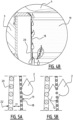
- the filter element comprises an adhesion plate provided behind the filter plate.
- a distance between the filter plate and the adhesion plate may decrease towards the surface water inlet.
- the adhesion plate may be perforated.
- the filter plate and the adhesion plate define an angle with respect to each other.
- the adhesion plate is preferably located closer to the filter plate at the inlet side of the filter element than at the outlet side of the filter element.
- the well housing is at least partially made of concrete.
- the concrete may be reinforced concrete.
- the filter unit may be mounted to the concrete material of the well housing, preferably by partially casting the filter unit, or particularly mounting brackets thereof, into the concrete material. Accordingly, a flush transition can be made between the inner wall of the well housing and the outer surface (i.e., filter surface) of the filter element of the filter unit.
- the filter unit may be cast into concrete to form the well housing around a prefabricated filter unit.
- the drainage well further comprises an overflow reservoir located between the surface water inlet and the filter unit, wherein an overflow outlet of the overflow reservoir provides the surface water to the filter unit.
- the overflow reservoir may be formed by a storm drain or the like, or a perforated basket placed under the inlet of the drainage well.
- the surface water inlet is provided with an inlet cover, preferably made of metal.
- the inlet cover may for instance be an inlet grate or a manhole cover. The inlet cover prevents large items, persons and animals from entering the drainage well unintentionally.
- the drainage well further comprises a prefilter located between the surface water inlet and the filter unit.
- the prefilter may for instance be a filter grate through which the surface water passes, or a perforated basket or the like.
- the prefilter may be removable, for instance through an access hatch (e.g., manhole cover) to be periodically cleaned.
- the present disclosure also relates to a filter unit according to the above, which is sized to be installed in existing drainage wells. Accordingly, the present disclosure provides a filter unit configured to be installed within a well housing of a drainage well, between a surface water inlet and a wastewater outlet of the well, wherein the filter unit comprises a filter element configured to form at least part of a flow surface along which surface water (taken in by the well) flows from the surface water inlet to the wastewater outlet, and wherein the filter unit is configured to be connected to a filtrate outlet that is configured to drain the filtrate collected by the filter unit from the drainage well.
- a pavement surface water infiltration system comprising a pavement drainage well according to any of the preceding embodiments, and an infiltration reservoir connected to the filtrate outlet for receiving the filtrate from the filter unit.
- a balanced water table e.g., ground water level
- At least part of the infiltration reservoir may have an open structure.
- the infiltration reservoir is lined with a porous material, such as geotextile or a mesh material or the like. Accordingly, the filtered water (i.e., the filtrate collected by the filter unit) can be provided to the surrounding soil at a controlled rate.
- the use of filtrate instead of direct surface runoff prevents blockage of the reservoir, such that the effective lifetime of the reservoir is significantly prolonged.
- the system further comprises a venting duct connected with the infiltration reservoir and the well housing, wherein an outlet of the venting duct at the well housing is located above the surface water inlet, such that surface water does not directly enter the venting duct.
- a method for providing infiltration in the vicinity of a paved surface comprising the steps of:
- the system comprises the venting duct
- the method further comprises a step of connecting the venting duct to the infiltration reservoir and the well.
- the step of connecting the surface water inlet of the well to the paved surface comprises connecting the water inlet of the well to an existing storm drain of the paved surface.
- the paved surface is a pavement, such as a road, for pedestrian or vehicle traffic.
- the step of burying the pavement drainage well may comprise burying the well under or adjacent to the paved surface.
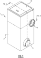
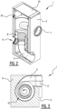
- FIGS. 2 and 3 present cross-sectional views along the arrows indicated in FIG. 1 .
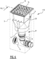
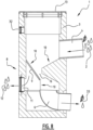
- the filter unit 8 and/or the filter element 9 of the well 1 of FIG. 6 may correspond to those of the well 1 of FIG. 4A-4B .
- At least part of the infiltration reservoir 27 has an open structure 28 from which water can infiltrate surrounding soil 29.
- the infiltration reservoir 27 can be lined with a porous material 30, such as geotextile.
- the system 26 shown in FIG. 9 provides infiltration in the vicinity of paved surface 5.
- Surface water 2 is drained from the paved surface 5 into storm drains 15, which lead to the surface water inlet 4 of a pavement drainage well 1.
- the surface water 2 is filtered in the pavement drainage well 1 as it is guided through the filter unit 8, in particular through the filter element 9 which separates the incoming surface water 2 into filtrate 12 and wastewater 33.
- the filtrate 12 is guided to the infiltration reservoir 27 via the filtrate outlet 11, while the wastewater 33 is guided to a sewer 7 via the wastewater outlet 6.
Landscapes
- Health & Medical Sciences (AREA)
- Life Sciences & Earth Sciences (AREA)
- Engineering & Computer Science (AREA)
- Hydrology & Water Resources (AREA)
- Public Health (AREA)
- Water Supply & Treatment (AREA)
- Chemical & Material Sciences (AREA)
- Chemical Kinetics & Catalysis (AREA)
- Sewage (AREA)
Claims (14)
- Puits de drainage de chaussée (1) destiné à drainer de l'eau de surface, comprenant :un corps de puits (3) comprenant une entrée d'eau de surface (4) conçue pour recevoir de l'eau de surface depuis une surface pavée (5), et une sortie d'eau usée (6) conçue pour être raccordée à un égout (7) ;une unité de filtre (8) placée au sein du corps de puits (3) entre l'entrée d'eau de surface (4) et la sortie d'eau usée (6), l'unité de filtre (8) comprenant un élément de filtre (9) formant un canal (16) qui fait au moins partie d'une surface d'écoulement continue (10) le long de laquelle l'eau de surface est conçue pour s'écouler depuis l'entrée d'eau de surface (4) pour passer le long et au-dessus de l'élément de filtre (9) vers la sortie d'eau usée (6), dans lequel la surface d'écoulement (10) définit un canal de drainage continu raccordant l'entrée d'eau de surface (4) à la sortie d'eau usée (6) ; etune sortie de filtrat (11) conçue pour drainer le filtrat collecté par l'unité de filtre (8) depuis le puits de drainage de chaussée (1),dans lequel l'élément de filtre (9) et/ou le canal (16) formé par l'élément de filtre (9) définit une interface entre le canal de drainage continu et la sortie de filtrat (11), et l'entrée d'eau de surface (4) est orientée par rapport au canal (16) formé par l'élément de filtre (9) de telle sorte qu'au moins une partie de l'eau de surface suit une trajectoire sensiblement hélicoïdale (17) à travers le canal (16).
- Puits de drainage de chaussée (1) selon la revendication 1, dans lequel le canal (16) s'étend depuis l'entrée d'eau de surface (4) jusqu'à la sortie d'eau usée (6).
- Puits de drainage de chaussée (1) selon la revendication 1 ou 2, dans lequel le canal (16) a une section transversale cylindrique et/ou se rétrécit vers la sortie d'eau usée (6).
- Puits de drainage de chaussée (1) selon l'une quelconque des revendications précédentes, dans lequel l'élément de filtre (9) comprend une plaque de filtre (18) avec une maille de filtre (19), de préférence dans lequel la plaque de filtre (18) est constituée d'acier inoxydable.
- Puits de drainage de chaussée (1) selon la revendication 4, dans lequel l'élément de filtre (9) comprend une plaque d'adhérence (20) fournie derrière la plaque de filtre (18).
- Puits de drainage de chaussée (1) selon la revendication 5, dans lequel une distance entre la plaque de filtre (18) et la plaque d'adhérence (20) diminue vers l'entrée d'eau de surface (4) et/ou dans lequel la plaque d'adhérence (20) est perforée.
- Puits de drainage de chaussée (1) selon l'une quelconque des revendications précédentes, dans lequel le corps de puits (3) est au moins partiellement constitué de béton, de préférence dans lequel l'unité de filtre (8) est montée sur le béton du corps de puits (3), de préférence par coulage partiel de l'unité de filtre (8) dans le béton.
- Puits de drainage de chaussée (1) selon l'une quelconque des revendications précédentes, comprenant en outre un réservoir de trop-plein (23) placé entre l'entrée d'eau de surface (4) et l'unité de filtre (8), dans lequel une sortie de trop-plein (25) du réservoir de trop-plein (23) fournit l'eau de surface à l'unité de filtre (8).
- Puits de drainage de chaussée (1) selon l'une quelconque des revendications précédentes, dans lequel l'entrée d'eau de surface (4) est pourvue d'un couvercle d'entrée (13), de préférence constitué de métal.
- Puits de drainage de chaussée (1) selon l'une quelconque des revendications précédentes, comprenant en outre un préfiltre (24) placé entre l'entrée d'eau de surface (4) et l'unité de filtre (8).
- Système d'infiltration d'eau de surface de chaussée (26), comprenant :un puits de drainage de chaussée (1) selon l'une quelconque des revendications précédentes ; etun réservoir d'infiltration (27) raccordé à la sortie de filtrat (11) pour la réception du filtrat depuis l'unité de filtre (8).
- Système d'infiltration d'eau de surface de chaussée (26) selon la revendication 11, dans lequel au moins une partie du réservoir d'infiltration (27) a une structure ouverte (28), de préférence dans lequel le réservoir d'infiltration (27) est revêtu d'un matériau poreux (30), tel qu'un géotextile.
- Système d'infiltration d'eau de surface de chaussée (26) selon la revendication 11 ou 12, comprenant en outre un conduit d'aération (31) raccordé avec le réservoir d'infiltration (27) et le corps de puits (3), dans lequel une sortie (32) du conduit d'aération (31) au niveau du corps de puits (3) est placée au-dessus de l'entrée d'eau de surface (4).
- Procédé destiné à fournir une infiltration à proximité d'une surface pavée (5), comprenant les étapes consistant à :fournir un système d'infiltration d'eau de surface de chaussée (26) selon l'une quelconque des revendications 11 à 13 ;enterrer le réservoir d'infiltration (27) à un emplacement nécessitant une augmentation d'infiltration à proximité de la surface pavée (5) ;enterrer le puits de drainage de chaussée (1) à proximité de la surface pavée (5) ;raccorder l'entrée d'eau de surface (4) du puits de drainage de chaussée (1) à la surface pavée (5) ; etraccorder le réservoir d'infiltration (27) à la sortie de filtrat (11) du puits de drainage de chaussée (1).
Priority Applications (3)
| Application Number | Priority Date | Filing Date | Title |
|---|---|---|---|
| EP23152040.4A EP4403714B1 (fr) | 2023-01-17 | 2023-01-17 | Puits de drainage de chaussée et système d'infiltration |
| PCT/EP2023/087622 WO2024141473A1 (fr) | 2022-12-30 | 2023-12-22 | Agencement de filtre d'eau de pluie et arbre de drainage de route |
| EP23840690.4A EP4441302A1 (fr) | 2022-12-30 | 2023-12-22 | Agencement de filtre d'eau de pluie et arbre de drainage de route |
Applications Claiming Priority (1)
| Application Number | Priority Date | Filing Date | Title |
|---|---|---|---|
| EP23152040.4A EP4403714B1 (fr) | 2023-01-17 | 2023-01-17 | Puits de drainage de chaussée et système d'infiltration |
Publications (3)
| Publication Number | Publication Date |
|---|---|
| EP4403714A1 EP4403714A1 (fr) | 2024-07-24 |
| EP4403714C0 EP4403714C0 (fr) | 2024-11-27 |
| EP4403714B1 true EP4403714B1 (fr) | 2024-11-27 |
Family
ID=84982159
Family Applications (1)
| Application Number | Title | Priority Date | Filing Date |
|---|---|---|---|
| EP23152040.4A Active EP4403714B1 (fr) | 2022-12-30 | 2023-01-17 | Puits de drainage de chaussée et système d'infiltration |
Country Status (1)
| Country | Link |
|---|---|
| EP (1) | EP4403714B1 (fr) |
Family Cites Families (3)
| Publication number | Priority date | Publication date | Assignee | Title |
|---|---|---|---|---|
| DE29502895U1 (de) * | 1995-02-24 | 1995-04-20 | Otto Graf GmbH Kunststofferzeugnisse, 79331 Teningen | Regenwasserfiltereinrichtung |
| BRPI1004676B1 (pt) * | 2010-11-04 | 2019-10-22 | Antonio Garios Wadih | sistema captador, classificador e separador de água pluvial |
| KR101936331B1 (ko) * | 2017-08-24 | 2019-01-08 | 알에스티이엔씨 주식회사 | 와류형 우수처리장치 |
-
2023
- 2023-01-17 EP EP23152040.4A patent/EP4403714B1/fr active Active
Also Published As
| Publication number | Publication date |
|---|---|
| EP4403714C0 (fr) | 2024-11-27 |
| EP4403714A1 (fr) | 2024-07-24 |
Similar Documents
| Publication | Publication Date | Title |
|---|---|---|
| US6093314A (en) | Drain insert for storm water sewer systems, and method of manufacture | |
| US8858804B2 (en) | Storm water pretreatment chamber | |
| KR101749656B1 (ko) | 친환경 여과 집수조 및 그것을 이용한 우수 재순환 시스템 | |
| KR101275666B1 (ko) | 도로의 우수받이 | |
| KR101582931B1 (ko) | 비점오염 저감 장치 | |
| KR101136508B1 (ko) | 안전을 고려한 하수도 빗물받이 | |
| KR100976853B1 (ko) | 집수정 | |
| JP4445168B2 (ja) | 雨水浸透システム | |
| EP4403714B1 (fr) | Puits de drainage de chaussée et système d'infiltration | |
| KR20090017869A (ko) | 수문이 부착된 경계블럭 | |
| KR101770105B1 (ko) | 협잡물 제거가 용이한 탈착식 거름망 시스템 | |
| CA3058918C (fr) | Filtre et piege precoules pour entree d'eau de ruissellement | |
| JP3728635B2 (ja) | 排水性舗装用排水路 | |
| KR200416889Y1 (ko) | 맨홀 구조. | |
| JP4153470B2 (ja) | 路面排水処理槽 | |
| US11298635B2 (en) | Storm water pretreatment chamber | |
| KR200311993Y1 (ko) | 우,오수 받이 연결뚜껑 | |
| KR100925648B1 (ko) | 안전을 고려한 하수도 빗물받이 | |
| KR101293048B1 (ko) | 하수의 악취 방지시스템 | |
| KR102789466B1 (ko) | 도로용 배수시스템 | |
| KR100750645B1 (ko) | 다기능 우수받이 | |
| KR102822205B1 (ko) | 보도형 침투 저류 시설과 보도형 침투 저류조 및 이의 시공 방법 | |
| KR100762979B1 (ko) | 도로의 오물 차단구조 | |
| JP2692951B2 (ja) | 浸透雨水桝 | |
| KR102638787B1 (ko) | 비점 오염 빗물 분리 정화 장치 및 그 시공 방법 |
Legal Events
| Date | Code | Title | Description |
|---|---|---|---|
| STAA | Information on the status of an ep patent application or granted ep patent |
Free format text: STATUS: EXAMINATION IS IN PROGRESS |
|
| PUAI | Public reference made under article 153(3) epc to a published international application that has entered the european phase |
Free format text: ORIGINAL CODE: 0009012 |
|
| 17P | Request for examination filed |
Effective date: 20231115 |
|
| AK | Designated contracting states |
Kind code of ref document: A1 Designated state(s): AL AT BE BG CH CY CZ DE DK EE ES FI FR GB GR HR HU IE IS IT LI LT LU LV MC ME MK MT NL NO PL PT RO RS SE SI SK SM TR |
|
| GRAP | Despatch of communication of intention to grant a patent |
Free format text: ORIGINAL CODE: EPIDOSNIGR1 |
|
| STAA | Information on the status of an ep patent application or granted ep patent |
Free format text: STATUS: GRANT OF PATENT IS INTENDED |
|
| INTG | Intention to grant announced |
Effective date: 20240801 |
|
| GRAS | Grant fee paid |
Free format text: ORIGINAL CODE: EPIDOSNIGR3 |
|
| GRAA | (expected) grant |
Free format text: ORIGINAL CODE: 0009210 |
|
| STAA | Information on the status of an ep patent application or granted ep patent |
Free format text: STATUS: THE PATENT HAS BEEN GRANTED |
|
| AK | Designated contracting states |
Kind code of ref document: B1 Designated state(s): AL AT BE BG CH CY CZ DE DK EE ES FI FR GB GR HR HU IE IS IT LI LT LU LV MC ME MK MT NL NO PL PT RO RS SE SI SK SM TR |
|
| REG | Reference to a national code |
Ref country code: GB Ref legal event code: FG4D |
|
| REG | Reference to a national code |
Ref country code: CH Ref legal event code: EP |
|
| REG | Reference to a national code |
Ref country code: IE Ref legal event code: FG4D |
|
| REG | Reference to a national code |
Ref country code: DE Ref legal event code: R096 Ref document number: 602023001118 Country of ref document: DE |
|
| U01 | Request for unitary effect filed |
Effective date: 20241219 |
|
| U07 | Unitary effect registered |
Designated state(s): AT BE BG DE DK EE FI FR IT LT LU LV MT NL PT RO SE SI Effective date: 20250113 |
|
| U20 | Renewal fee for the european patent with unitary effect paid |
Year of fee payment: 3 Effective date: 20250127 |
|
| PG25 | Lapsed in a contracting state [announced via postgrant information from national office to epo] |
Ref country code: IS Free format text: LAPSE BECAUSE OF FAILURE TO SUBMIT A TRANSLATION OF THE DESCRIPTION OR TO PAY THE FEE WITHIN THE PRESCRIBED TIME-LIMIT Effective date: 20250327 Ref country code: HR Free format text: LAPSE BECAUSE OF FAILURE TO SUBMIT A TRANSLATION OF THE DESCRIPTION OR TO PAY THE FEE WITHIN THE PRESCRIBED TIME-LIMIT Effective date: 20241127 |
|
| PG25 | Lapsed in a contracting state [announced via postgrant information from national office to epo] |
Ref country code: ES Free format text: LAPSE BECAUSE OF FAILURE TO SUBMIT A TRANSLATION OF THE DESCRIPTION OR TO PAY THE FEE WITHIN THE PRESCRIBED TIME-LIMIT Effective date: 20241127 |
|
| PG25 | Lapsed in a contracting state [announced via postgrant information from national office to epo] |
Ref country code: NO Free format text: LAPSE BECAUSE OF FAILURE TO SUBMIT A TRANSLATION OF THE DESCRIPTION OR TO PAY THE FEE WITHIN THE PRESCRIBED TIME-LIMIT Effective date: 20250227 |
|
| PG25 | Lapsed in a contracting state [announced via postgrant information from national office to epo] |
Ref country code: GR Free format text: LAPSE BECAUSE OF FAILURE TO SUBMIT A TRANSLATION OF THE DESCRIPTION OR TO PAY THE FEE WITHIN THE PRESCRIBED TIME-LIMIT Effective date: 20250228 |
|
| PG25 | Lapsed in a contracting state [announced via postgrant information from national office to epo] |
Ref country code: PL Free format text: LAPSE BECAUSE OF FAILURE TO SUBMIT A TRANSLATION OF THE DESCRIPTION OR TO PAY THE FEE WITHIN THE PRESCRIBED TIME-LIMIT Effective date: 20241127 |
|
| PG25 | Lapsed in a contracting state [announced via postgrant information from national office to epo] |
Ref country code: RS Free format text: LAPSE BECAUSE OF FAILURE TO SUBMIT A TRANSLATION OF THE DESCRIPTION OR TO PAY THE FEE WITHIN THE PRESCRIBED TIME-LIMIT Effective date: 20250227 |
|
| PG25 | Lapsed in a contracting state [announced via postgrant information from national office to epo] |
Ref country code: SM Free format text: LAPSE BECAUSE OF FAILURE TO SUBMIT A TRANSLATION OF THE DESCRIPTION OR TO PAY THE FEE WITHIN THE PRESCRIBED TIME-LIMIT Effective date: 20241127 |
|
| PG25 | Lapsed in a contracting state [announced via postgrant information from national office to epo] |
Ref country code: SK Free format text: LAPSE BECAUSE OF FAILURE TO SUBMIT A TRANSLATION OF THE DESCRIPTION OR TO PAY THE FEE WITHIN THE PRESCRIBED TIME-LIMIT Effective date: 20241127 |
|
| PG25 | Lapsed in a contracting state [announced via postgrant information from national office to epo] |
Ref country code: CZ Free format text: LAPSE BECAUSE OF FAILURE TO SUBMIT A TRANSLATION OF THE DESCRIPTION OR TO PAY THE FEE WITHIN THE PRESCRIBED TIME-LIMIT Effective date: 20241127 |
|
| PG25 | Lapsed in a contracting state [announced via postgrant information from national office to epo] |
Ref country code: MC Free format text: LAPSE BECAUSE OF FAILURE TO SUBMIT A TRANSLATION OF THE DESCRIPTION OR TO PAY THE FEE WITHIN THE PRESCRIBED TIME-LIMIT Effective date: 20241127 |
|
| PLBE | No opposition filed within time limit |
Free format text: ORIGINAL CODE: 0009261 |
|
| STAA | Information on the status of an ep patent application or granted ep patent |
Free format text: STATUS: NO OPPOSITION FILED WITHIN TIME LIMIT |
|
| 26N | No opposition filed |
Effective date: 20250828 |