EP4403714A1 - Strassenentwässerungsschacht und infiltrationssystem - Google Patents
Strassenentwässerungsschacht und infiltrationssystem Download PDFInfo
- Publication number
- EP4403714A1 EP4403714A1 EP23152040.4A EP23152040A EP4403714A1 EP 4403714 A1 EP4403714 A1 EP 4403714A1 EP 23152040 A EP23152040 A EP 23152040A EP 4403714 A1 EP4403714 A1 EP 4403714A1
- Authority
- EP
- European Patent Office
- Prior art keywords
- surface water
- well
- water inlet
- filter
- filter unit
- Prior art date
- Legal status (The legal status is an assumption and is not a legal conclusion. Google has not performed a legal analysis and makes no representation as to the accuracy of the status listed.)
- Granted
Links
Images


Classifications
-
- B—PERFORMING OPERATIONS; TRANSPORTING
- B01—PHYSICAL OR CHEMICAL PROCESSES OR APPARATUS IN GENERAL
- B01D—SEPARATION
- B01D29/00—Filters with filtering elements stationary during filtration, e.g. pressure or suction filters, not covered by groups B01D24/00 - B01D27/00; Filtering elements therefor
- B01D29/88—Filters with filtering elements stationary during filtration, e.g. pressure or suction filters, not covered by groups B01D24/00 - B01D27/00; Filtering elements therefor having feed or discharge devices
- B01D29/90—Filters with filtering elements stationary during filtration, e.g. pressure or suction filters, not covered by groups B01D24/00 - B01D27/00; Filtering elements therefor having feed or discharge devices for feeding
- B01D29/908—Filters with filtering elements stationary during filtration, e.g. pressure or suction filters, not covered by groups B01D24/00 - B01D27/00; Filtering elements therefor having feed or discharge devices for feeding provoking a tangential stream
-
- B—PERFORMING OPERATIONS; TRANSPORTING
- B01—PHYSICAL OR CHEMICAL PROCESSES OR APPARATUS IN GENERAL
- B01D—SEPARATION
- B01D29/00—Filters with filtering elements stationary during filtration, e.g. pressure or suction filters, not covered by groups B01D24/00 - B01D27/00; Filtering elements therefor
- B01D29/11—Filters with filtering elements stationary during filtration, e.g. pressure or suction filters, not covered by groups B01D24/00 - B01D27/00; Filtering elements therefor with bag, cage, hose, tube, sleeve or like filtering elements
- B01D29/31—Self-supporting filtering elements
- B01D29/35—Self-supporting filtering elements arranged for outward flow filtration
- B01D29/356—Self-supporting filtering elements arranged for outward flow filtration open-ended, the arrival of the mixture to be filtered and the discharge of the concentrated mixture are situated on both opposite sides of the filtering element
-
- E—FIXED CONSTRUCTIONS
- E03—WATER SUPPLY; SEWERAGE
- E03F—SEWERS; CESSPOOLS
- E03F1/00—Methods, systems, or installations for draining-off sewage or storm water
- E03F1/002—Methods, systems, or installations for draining-off sewage or storm water with disposal into the ground, e.g. via dry wells
-
- E—FIXED CONSTRUCTIONS
- E03—WATER SUPPLY; SEWERAGE
- E03F—SEWERS; CESSPOOLS
- E03F5/00—Sewerage structures
- E03F5/04—Gullies inlets, road sinks, floor drains with or without odour seals or sediment traps
- E03F5/0401—Gullies for use in roads or pavements
- E03F5/0404—Gullies for use in roads or pavements with a permanent or temporary filtering device; Filtering devices specially adapted therefor
Definitions
- the present disclosure relates to a pavement drainage well for draining surface water from a paved surface, and pavement surface water infiltration system employing such drainage well.
- Pavements which are also referred to as road surfaces, are paved surfaces that are intended for vehicular and foot traffic. Pavements include, for instance, roads, sidewalks, walkways, bridges, bicycle lanes, squares, plazas, parking lots, et cetera. These are generally provided on the ground, which provides the base on which such pavements are placed. Paved surfaces can for instance be surfaces that are provided with asphalt, stone tiles, concrete, rubber, or other hardened and/or durable surface materials. Generally, such materials provide a suitable, solid and durable base for transportation (e.g., walking or driving), but are less suitable for draining water (e.g., from precipitation such as rain or snow) and other waste products (e.g., dust, leaf litter, debris, et cetera).
- water e.g., from precipitation such as rain or snow
- other waste products e.g., dust, leaf litter, debris, et cetera
- pavements are generally provided with drainage systems, which may include storm drains and/or drainage wells that are connected to bodies of water (such as lakes or rivers), reservoirs, and/or a sewage system.
- drainage systems can prevent flooding of pavements, and can assist in clearing the pavements of waste products. Drainage systems have to be maintained periodically to clear debris from their internal (overflow) reservoirs and to clear inlet grates and such.
- water table e.g., ground water
- the present disclosure provides a pavement drainage well for draining surface water, comprising a well housing with a surface water inlet configured to receive surface water from a paved surface, and a wastewater outlet configured to be connected to a sewer or other water body or reservoir, a filter unit located within the well housing between the surface water inlet and the wastewater outlet, the filter unit comprising a filter element forming at least part of a flow surface along which the surface water flows from the surface water inlet to the wastewater outlet, and a filtrate outlet configured to drain the filtrate collected by the filter unit from the drainage well.
- filtered water can be collected (i.e., the filtrate collected by the filter unit) which can subsequently be provided to the water table of the surrounding area, for instance via an infiltration reservoir or the like, or can be provided to agricultural processes or the like.
- the present drainage well has a low maintenance requirement because it is (a part of) the flow surface along which the surface water flows from the surface water inlet to the wastewater outlet of the well. A part of the surface water thereby cleans the exterior surface of the filter element, which makes the filter unit essentially self-cleaning.
- the present drainage well provides a significant amount of useful filtered water.
- the present drainage well has a positive effect on the environment by providing filtered water, and requires less maintenance as compared to drainage systems and/or associated filters according to the state of the art.
- the flow surface may be configured to guide the surface water from the surface water inlet to pass along and over the filter element towards the wastewater outlet.
- the flow surface may be continuous from the surface water inlet to the wastewater outlet.
- the filter element may form at least part of such continuous flow surface over which the surface water flows from the surface water inlet to the wastewater outlet.
- the flow surface may define a continuous drainage channel from the surface water inlet to the wastewater outlet, the filter element forming at least a part of this continuous drainage channel while leaving free the continuous channel.
- the filter element may form a wall section of such continuous drainage channel.
- the well housing may be an elongate housing, preferably rectangular, that is provided underground at a level below the paved surface.
- the housing is generally made of concrete, preferably reinforced concrete.
- the surface water inlet is provided at a location higher than the wastewater outlet, such that the transport of the surface water past the filter and to the outlet is provided by gravity.
- One or more storm drains can be connected to the drainage well, and/or a storm drain can be integrated with the drainage well.
- the filter unit and/or the filter element are removably mounted in the well, so as to be replaceable.
- An access hatch, or the like, of the well housing is preferably sized to accommodate the removal of the filter unit and/or filter element.
- the filter element forms a channel arranged between the surface water inlet to the wastewater outlet.
- the channel may be extend from the surface water inlet to the wastewater outlet.
- the channel may have a (partially or fully) cylindrical cross-section.
- the channel narrows towards the wastewater outlet.
- the channel may have a frustoconical shape or a funnel shape.
- the channel has an inlet side and an outlet side, wherein the inlet side is closer to the surface water inlet than the wastewater outlet, and the outlet side is closer to the wastewater outlet than the surface water inlet.
- the inlet side may be flush with (part of) an interior wall of the well housing.
- the outlet side may be flush with (part of) the wastewater outlet.
- the surface water inlet is oriented relative to the channel such that at least part of the surface water is guided to follow a substantially helical path through the channel.
- the inlet may for instance direct the surface water perpendicularly to a central axis of the channel, and at a distance therefrom (i.e., in a tangential direction relative to the central axis), so as to provide the water with a swirl or rotation with respect to the channel.
- the filter element of the filter unit can function as a cyclone filter, wherein the centrifugal force acting upon the water aids in the water passing through the filter.
- the rotating path of the water along the filter element also increases the effective filter surface of the filter element, as the water tends to pass a large portion of the filter element.
- the filter element comprises a filter plate with a filter mesh, preferably wherein the filter plate is made of stainless steel.
- the filter mesh has a mesh size (i.e., pore size) of approximately between 50 ⁇ m to 500 ⁇ m.
- a more preferable mesh size is in the range of 100 ⁇ m to 300 ⁇ m, most preferably 100 ⁇ m to 280 ⁇ m.
- the mesh size may vary over the surface of the filter mesh, such that at one location on the filter mesh the mesh size differs from the mesh size at another location on the filter mesh.
- the filter element comprises an adhesion plate provided behind the filter plate.
- a distance between the filter plate and the adhesion plate may decreases towards the surface water inlet.
- the adhesion plate may be perforated.
- the filter plate and the adhesion plate define an angle with respect to each other.
- the adhesion plate is preferably located closer to the filter plate at the inlet side of the filter element than at the outlet side of the filter element.
- the well housing is at least partially made of concrete.
- the concrete may be reinforced concrete.
- the filter unit may be mounted to the concrete material of the well housing, preferably by partially casting the filter unit, or particularly mounting brackets thereof, into the concrete material. Accordingly, a flush transition can be made between the inner wall of the well housing and the outer surface (i.e., filter surface) of the filter element of the filter unit.
- the filter unit may be cast into concrete to form the well housing around a prefabricated filter unit.
- the drainage well further comprises an overflow reservoir located between the surface water inlet and the filter unit, wherein an overflow outlet of the overflow reservoir provides the surface water to the filter unit.
- the overflow reservoir may be formed by a storm drain or the like, or a perforated basket placed under the inlet of the drainage well.
- the surface water inlet is provided with an inlet cover, preferably made of metal.
- the inlet cover may for instance be an inlet grate or a manhole cover. The inlet cover prevents large items, persons and animals from entering the drainage well unintentionally.
- the drainage well further comprises a prefilter located between the surface water inlet and the filter unit.
- the prefilter may for instance be a filter grate through which the surface water passes, or a perforated basket or the like.
- the prefilter may be removable, for instance through an access hatch (e.g., manhole cover) to be periodically cleaned.
- the present disclosure also relates to a filter unit according to the above, which is sized to be installed in existing drainage wells. Accordingly, the present disclosure provides a filter unit configured to be installed within a well housing of a drainage well, between a surface water inlet and a wastewater outlet of the well, wherein the filter unit comprises a filter element configured to form at least part of a flow surface along which surface water (taken in by the well) flows from the surface water inlet to the wastewater outlet, and wherein the filter unit is configured to be connected to a filtrate outlet that is configured to drain the filtrate collected by the filter unit from the drainage well.
- a pavement surface water infiltration system comprising a pavement drainage well according to any of the preceding embodiments, and an infiltration reservoir connected to the filtrate outlet for receiving the filtrate from the filter unit.
- a balanced water table e.g., ground water level
- At least part of the infiltration reservoir may have an open structure.
- the infiltration reservoir is lined with a porous material, such as geotextile or a mesh material or the like.
- the filtered water i.e., the filtrate collected by the filter unit
- the filtered water can be provided to the surrounding soil at a controlled rate.
- the use of filtrate instead of direct surface runoff prevents blockage of the reservoir, such that the effective lifetime of the reservoir is significantly prolonged.
- the system further comprises a venting duct connected with the infiltration reservoir and the well housing, wherein an outlet of the venting duct at the well housing is located above the surface water inlet, such that surface water does not directly enter the venting duct.
- a method for providing infiltration in the vicinity of a paved surface comprising the steps of:
- the system comprises the venting duct
- the method further comprises a step of connecting the venting duct to the infiltration reservoir and the well.
- the step of connecting the surface water inlet of the well to the paved surface comprises connecting the water inlet of the well to an existing storm drain of the paved surface.
- the paved surface is a pavement, such as a road, for pedestrian or vehicle traffic.
- the step of burying the pavement drainage well may comprise burying the well under or adjacent to the paved surface.
- the step of burying the infiltration reservoir comprising burying the reservoir at a level lower than the filtrate outlet of the well.
- the above method according to the third aspect, and the preferred embodiments thereof, are able to provide infiltration in environments that are in need of increased infiltration, such as urban environments and other built-up environments wherein precipitation may be prevented from sufficiently reaching the water table (e.g., seeping into the ground).
- barriers may exist that prevent the precipitation from reaching the soil beneath.
- These barriers are generally paved surfaces (e.g., roads, parking areas, footpaths, bicycle lanes, et cetera), or other structures (e.g., bridges, foundations, buildings, walls, et cetera).
- the present method thus benefits infiltration in such areas, thereby preventing damage to vegetation and buildings, and possibly the paved surface itself, due to lack of infiltration which may for instance cause subsidence or soil erosion.
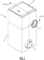
- a pavement drainage well 1 for draining surface water 2 is illustrated.
- the pavement drainage well 1 comprises a well housing 3 with a surface water inlet 4 that is configured to receive surface water 2 from a paved surface 5, and with a wastewater outlet 6 that is configured to be connected to a sewer 7.
- a filter unit 8 is located within the well housing 3 between the surface water inlet 4 and the wastewater outlet 6.
- the filter unit 8 comprises a filter element 9 forming at least part of a flow surface 10 along which the surface water 2 flows from the surface water inlet 4 to the wastewater outlet 6.
- the pavement drainage well 1 further comprises a filtrate outlet 11 configured to drain the filtrate 12 collected by the filter unit 8 from the well 1.
- An access hatch 13 is provided at a top surface of the well 1.
- the access hatch 13 may be provided with openings 14 (illustrated as a grating in FIGS. 6-7 ), in particular when the well 1 is implemented as a storm drain 15.
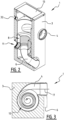
- FIGS. 2 and 3 present cross-sectional views along the arrows indicated in FIG. 1 .
- the filter element 9 forms a channel 16 from the surface water inlet 4 to the wastewater outlet 6.
- Surface water 2 introduced through the surface water inlet 4 flows over the channel 16 formed by the filter element 9 to, on the one hand, the wastewater outlet 6 and, on the other hand, to filtrate outlet 11.
- the filter element 9 ensures separation of coarse and particulate matter (illustrated as a leaf), including contaminating substances that stick to such particulate matter, from most of the water which forms the filtrate 12.
- the channel 16 is illustrated with a cylindrical cross-section, though the channel 16 may have various geometric shapes connecting the surface water inlet 4 to the wastewater outlet 6.
- the filter element 9 is shown as having a flat shape.
- Various constructions of the well 1 are envisioned, as long as the incoming surface water 2 is (at least partially) guided along (i.e., over) the surface of the filter element 9 towards the wastewater outlet 6.
- the filter element 9 and/or the channel 16 it forms, defines an interface between a continuous drainage channel connecting the surface water inlet 4 to the wastewater outlet 6 and the filtrate outlet 11.
- the filter element 9 of the pavement drainage well 1 of FIG. 8 may also comprise the filter plate 18 having the filter mesh 19 and may further comprise the adhesion plate 20 with or without perforations 22.
- FIG. 4B it can be seen that the channel 16 narrows towards the wastewater outlet 6.
- the surface water inlet 4 is oriented relative to the channel 16 such that at least part of the surface water 2 follows a substantially helical path 17 through the channel 16.
- a helical path 17 is also illustrated in the well 1 of FIG. 7 .
- the helical path 17 may be initiated by the form of the surface water inlet 4.
- the surface water inlet 4 may be configured to direct incoming surface water 2 along a tangential path, e.g. relative to a vertical direction of the channel 16 in the well 1.
- the filter element 9 comprises a filter plate 18 with a filter mesh 19.
- the filter plate is 18 can be made of stainless steel.
- the filter element 9 also comprises an adhesion plate 20 provided behind the filter plate 18.
- the adhesion plate 20 is arranged behind the filter plate 18 as seen relative to the flow direction of filtrate originating from the surface water 2 through the filter element 9.
- a distance 21 between the filter plate 18 and the adhesion plate 20 decreases towards the surface water inlet 4.
- the adhesion plate 20 is illustrated with perforations 22 which serve to increase filtrate 12 throughput.
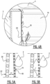
- FIG. 5A and 5B illustrate the working principle of the filter element 9 comprising the filter plate 18 with its filter mesh 19 and an adhesion plate 20. Due to forces of adhesion (related to wetting), water is attracted to the surface of the filter mesh 19 and thereby passes through the filter mesh 19 and may reach the adhesion plate 20 arranged behind the filter mesh 19. Due to forces of cohesion (related to surface tension), more water is drawn towards the adhesion plate 20. As the water falls down to due gravity, an increased separation distance 21 between the filter plate 18 and the adhesion plate 20 can accommodate increasing amounts of filtrate 12. The perforations 22 in the adhesion plate 20 may further increase the capacity of the filter element 9 to withdraw filtrate or water 12 from the surface water 2 passing along the filter element 9.
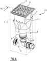
- FIGS. 6 and 7 illustrate a pavement drainage well 1 with integrated storm drain 15.
- a storm drain 15 generally comprises an overflow reservoir 23, which allows particular matter or other debris to settle.
- the overflow reservoir 23 may thus perform the function of a prefilter 24.
- the illustrated well 1 comprises an overflow reservoir 23 arranged between the surface water inlet 4 and the filter unit 8.
- An overflow outlet 25 of the overflow reservoir 23 provides the surface water 2 to the filter unit 8.
- the overflow reservoir 23 is illustrated as a bucket with openings forming overflow outlets 25.
- the bucket or overflow reservoir 23 can be made of a perforated sheet material, such as stainless steel, to perform a prefilter function.
- the overflow reservoir or bucket 23 is provided with a handle 34 for easy removal from the well 1 for emptying of the overflow reservoir 23 and other maintenance.
- the storm drain of FIG. 6 is provided with an inlet cover 13 in form of hatched inlet grate.
- Inlet covers or access hatches 13 are preferably made metal such as cast iron.
- the inlet cover or hatch 13 is opened, settled debris can be cleared from the overflow reservoir 23.
- the overflow reservoir 23 may be removable arranged onto the filter unit 8, for example as illustrated.
- the filter unit 8 and/or the filter element 9 of the well 1 of FIG. 6 may correspond to those of the well 1 of FIG. 4A-4B .
- the well housing 3 is at least partially made of concrete.
- the filter unit 8 is mounted to the concrete of the well housing 3, preferably by partially casting the filter unit 8 into the concrete.
- the filter unit 8 may be arranged or cast into the concrete well housing 3, with an access hatch or inlet cover 13 arranged at the top. Prior to casting, the filter unit 8 may be modularly assembled.
- the filter element 9 may be removably arranged in the well 1. For example by being supported onto the surface water inlet 4 and/or the wastewater outlet 6. When the hatch 13 is opened, the filter element 9 can be removed, serviced, or replaced.
- FIG. 9 illustrates how the pavement drainage well 1 can be employed in a pavement surface water infiltration system 26.
- the pavement surface water infiltration system 26 comprises the pavement drainage well 1 according to the present disclosure as well as an infiltration reservoir 27 connected to the filtrate outlet 11 for receiving the filtrate 12 from the filter unit 8 of the well 1.
- At least part of the infiltration reservoir 27 has an open structure 28 from which water can infiltrate surrounding soil 29.
- the infiltration reservoir 27 can be lined with a porous material 30, such as geotextile.
- the system 26 further comprises a venting duct 31 connected with the infiltration reservoir 27, for example with a top surface thereof, and the well housing 3.
- An outlet 31 of the venting duct at the well housing 3 is located above the surface water inlet 4.
- the system 26 shown in FIG. 9 provides infiltration in the vicinity of paved surface 5.
- Surface water 2 is drained from the paved surface 5 into storm drains 15, which lead to the surface water inlet 4 of a pavement drainage well 1.
- the surface water 2 is filtered in the pavement drainage well 1 as it is guided through the filter unit 8, in particular through the filter element 9 which separates the incoming surface water 2 into filtrate 12 and wastewater 33.
- the filtrate 12 is guided to the infiltration reservoir 27 via the filtrate outlet 11, while the wastewater 33 is guided to a sewer 7 via the wastewater outlet 6.
Landscapes
- Health & Medical Sciences (AREA)
- Life Sciences & Earth Sciences (AREA)
- Engineering & Computer Science (AREA)
- Hydrology & Water Resources (AREA)
- Public Health (AREA)
- Water Supply & Treatment (AREA)
- Chemical & Material Sciences (AREA)
- Chemical Kinetics & Catalysis (AREA)
- Sewage (AREA)
Priority Applications (3)
| Application Number | Priority Date | Filing Date | Title |
|---|---|---|---|
| EP23152040.4A EP4403714B1 (de) | 2023-01-17 | 2023-01-17 | Strassenentwässerungsschacht und infiltrationssystem |
| PCT/EP2023/087622 WO2024141473A1 (de) | 2022-12-30 | 2023-12-22 | REGENWASSERFILTERANORDNUNG UND STRAßENENTWÄSSERUNGSSCHACHT |
| EP23840690.4A EP4441302A1 (de) | 2022-12-30 | 2023-12-22 | REGENWASSERFILTERANORDNUNG UND STRAßENENTWÄSSERUNGSSCHACHT |
Applications Claiming Priority (1)
| Application Number | Priority Date | Filing Date | Title |
|---|---|---|---|
| EP23152040.4A EP4403714B1 (de) | 2023-01-17 | 2023-01-17 | Strassenentwässerungsschacht und infiltrationssystem |
Publications (3)
| Publication Number | Publication Date |
|---|---|
| EP4403714A1 true EP4403714A1 (de) | 2024-07-24 |
| EP4403714C0 EP4403714C0 (de) | 2024-11-27 |
| EP4403714B1 EP4403714B1 (de) | 2024-11-27 |
Family
ID=84982159
Family Applications (1)
| Application Number | Title | Priority Date | Filing Date |
|---|---|---|---|
| EP23152040.4A Active EP4403714B1 (de) | 2022-12-30 | 2023-01-17 | Strassenentwässerungsschacht und infiltrationssystem |
Country Status (1)
| Country | Link |
|---|---|
| EP (1) | EP4403714B1 (de) |
Citations (3)
| Publication number | Priority date | Publication date | Assignee | Title |
|---|---|---|---|---|
| DE29502895U1 (de) * | 1995-02-24 | 1995-04-20 | Otto Graf GmbH Kunststofferzeugnisse, 79331 Teningen | Regenwasserfiltereinrichtung |
| US20170088437A1 (en) * | 2010-11-04 | 2017-03-30 | Wadih Antonio Garios | Apparatus to classify and separate turbid water and clean water |
| KR101936331B1 (ko) * | 2017-08-24 | 2019-01-08 | 알에스티이엔씨 주식회사 | 와류형 우수처리장치 |
-
2023
- 2023-01-17 EP EP23152040.4A patent/EP4403714B1/de active Active
Patent Citations (3)
| Publication number | Priority date | Publication date | Assignee | Title |
|---|---|---|---|---|
| DE29502895U1 (de) * | 1995-02-24 | 1995-04-20 | Otto Graf GmbH Kunststofferzeugnisse, 79331 Teningen | Regenwasserfiltereinrichtung |
| US20170088437A1 (en) * | 2010-11-04 | 2017-03-30 | Wadih Antonio Garios | Apparatus to classify and separate turbid water and clean water |
| KR101936331B1 (ko) * | 2017-08-24 | 2019-01-08 | 알에스티이엔씨 주식회사 | 와류형 우수처리장치 |
Also Published As
| Publication number | Publication date |
|---|---|
| EP4403714C0 (de) | 2024-11-27 |
| EP4403714B1 (de) | 2024-11-27 |
Similar Documents
| Publication | Publication Date | Title |
|---|---|---|
| US6093314A (en) | Drain insert for storm water sewer systems, and method of manufacture | |
| US8501016B2 (en) | Storm water pretreatment chamber | |
| KR101749656B1 (ko) | 친환경 여과 집수조 및 그것을 이용한 우수 재순환 시스템 | |
| KR101963429B1 (ko) | 측구 구조체 | |
| KR101582931B1 (ko) | 비점오염 저감 장치 | |
| KR101136508B1 (ko) | 안전을 고려한 하수도 빗물받이 | |
| KR100976853B1 (ko) | 집수정 | |
| KR100941693B1 (ko) | 집수정 | |
| JP4445168B2 (ja) | 雨水浸透システム | |
| EP4403714A1 (de) | Strassenentwässerungsschacht und infiltrationssystem | |
| KR20090014529A (ko) | 배수관에서 배수 유도장치 | |
| KR20090017869A (ko) | 수문이 부착된 경계블럭 | |
| KR101770105B1 (ko) | 협잡물 제거가 용이한 탈착식 거름망 시스템 | |
| CA3058918C (en) | Precast stormwater inlet filter and trap | |
| JP3728635B2 (ja) | 排水性舗装用排水路 | |
| KR200416889Y1 (ko) | 맨홀 구조. | |
| KR200311993Y1 (ko) | 우,오수 받이 연결뚜껑 | |
| JP4153470B2 (ja) | 路面排水処理槽 | |
| KR102822205B1 (ko) | 보도형 침투 저류 시설과 보도형 침투 저류조 및 이의 시공 방법 | |
| KR101293048B1 (ko) | 하수의 악취 방지시스템 | |
| KR100925648B1 (ko) | 안전을 고려한 하수도 빗물받이 | |
| KR100762979B1 (ko) | 도로의 오물 차단구조 | |
| EP4538472A1 (de) | Ablauf | |
| KR102638787B1 (ko) | 비점 오염 빗물 분리 정화 장치 및 그 시공 방법 | |
| KR102789466B1 (ko) | 도로용 배수시스템 |
Legal Events
| Date | Code | Title | Description |
|---|---|---|---|
| STAA | Information on the status of an ep patent application or granted ep patent |
Free format text: STATUS: EXAMINATION IS IN PROGRESS |
|
| PUAI | Public reference made under article 153(3) epc to a published international application that has entered the european phase |
Free format text: ORIGINAL CODE: 0009012 |
|
| 17P | Request for examination filed |
Effective date: 20231115 |
|
| AK | Designated contracting states |
Kind code of ref document: A1 Designated state(s): AL AT BE BG CH CY CZ DE DK EE ES FI FR GB GR HR HU IE IS IT LI LT LU LV MC ME MK MT NL NO PL PT RO RS SE SI SK SM TR |
|
| GRAP | Despatch of communication of intention to grant a patent |
Free format text: ORIGINAL CODE: EPIDOSNIGR1 |
|
| STAA | Information on the status of an ep patent application or granted ep patent |
Free format text: STATUS: GRANT OF PATENT IS INTENDED |
|
| INTG | Intention to grant announced |
Effective date: 20240801 |
|
| GRAS | Grant fee paid |
Free format text: ORIGINAL CODE: EPIDOSNIGR3 |
|
| GRAA | (expected) grant |
Free format text: ORIGINAL CODE: 0009210 |
|
| STAA | Information on the status of an ep patent application or granted ep patent |
Free format text: STATUS: THE PATENT HAS BEEN GRANTED |
|
| AK | Designated contracting states |
Kind code of ref document: B1 Designated state(s): AL AT BE BG CH CY CZ DE DK EE ES FI FR GB GR HR HU IE IS IT LI LT LU LV MC ME MK MT NL NO PL PT RO RS SE SI SK SM TR |
|
| REG | Reference to a national code |
Ref country code: GB Ref legal event code: FG4D |
|
| REG | Reference to a national code |
Ref country code: CH Ref legal event code: EP |
|
| REG | Reference to a national code |
Ref country code: IE Ref legal event code: FG4D |
|
| REG | Reference to a national code |
Ref country code: DE Ref legal event code: R096 Ref document number: 602023001118 Country of ref document: DE |
|
| U01 | Request for unitary effect filed |
Effective date: 20241219 |
|
| U07 | Unitary effect registered |
Designated state(s): AT BE BG DE DK EE FI FR IT LT LU LV MT NL PT RO SE SI Effective date: 20250113 |
|
| U20 | Renewal fee for the european patent with unitary effect paid |
Year of fee payment: 3 Effective date: 20250127 |
|
| PG25 | Lapsed in a contracting state [announced via postgrant information from national office to epo] |
Ref country code: IS Free format text: LAPSE BECAUSE OF FAILURE TO SUBMIT A TRANSLATION OF THE DESCRIPTION OR TO PAY THE FEE WITHIN THE PRESCRIBED TIME-LIMIT Effective date: 20250327 Ref country code: HR Free format text: LAPSE BECAUSE OF FAILURE TO SUBMIT A TRANSLATION OF THE DESCRIPTION OR TO PAY THE FEE WITHIN THE PRESCRIBED TIME-LIMIT Effective date: 20241127 |
|
| PG25 | Lapsed in a contracting state [announced via postgrant information from national office to epo] |
Ref country code: ES Free format text: LAPSE BECAUSE OF FAILURE TO SUBMIT A TRANSLATION OF THE DESCRIPTION OR TO PAY THE FEE WITHIN THE PRESCRIBED TIME-LIMIT Effective date: 20241127 |
|
| PG25 | Lapsed in a contracting state [announced via postgrant information from national office to epo] |
Ref country code: NO Free format text: LAPSE BECAUSE OF FAILURE TO SUBMIT A TRANSLATION OF THE DESCRIPTION OR TO PAY THE FEE WITHIN THE PRESCRIBED TIME-LIMIT Effective date: 20250227 |
|
| PG25 | Lapsed in a contracting state [announced via postgrant information from national office to epo] |
Ref country code: GR Free format text: LAPSE BECAUSE OF FAILURE TO SUBMIT A TRANSLATION OF THE DESCRIPTION OR TO PAY THE FEE WITHIN THE PRESCRIBED TIME-LIMIT Effective date: 20250228 |
|
| PG25 | Lapsed in a contracting state [announced via postgrant information from national office to epo] |
Ref country code: PL Free format text: LAPSE BECAUSE OF FAILURE TO SUBMIT A TRANSLATION OF THE DESCRIPTION OR TO PAY THE FEE WITHIN THE PRESCRIBED TIME-LIMIT Effective date: 20241127 |
|
| PG25 | Lapsed in a contracting state [announced via postgrant information from national office to epo] |
Ref country code: RS Free format text: LAPSE BECAUSE OF FAILURE TO SUBMIT A TRANSLATION OF THE DESCRIPTION OR TO PAY THE FEE WITHIN THE PRESCRIBED TIME-LIMIT Effective date: 20250227 |
|
| PG25 | Lapsed in a contracting state [announced via postgrant information from national office to epo] |
Ref country code: SM Free format text: LAPSE BECAUSE OF FAILURE TO SUBMIT A TRANSLATION OF THE DESCRIPTION OR TO PAY THE FEE WITHIN THE PRESCRIBED TIME-LIMIT Effective date: 20241127 |
|
| PG25 | Lapsed in a contracting state [announced via postgrant information from national office to epo] |
Ref country code: SK Free format text: LAPSE BECAUSE OF FAILURE TO SUBMIT A TRANSLATION OF THE DESCRIPTION OR TO PAY THE FEE WITHIN THE PRESCRIBED TIME-LIMIT Effective date: 20241127 |
|
| PG25 | Lapsed in a contracting state [announced via postgrant information from national office to epo] |
Ref country code: CZ Free format text: LAPSE BECAUSE OF FAILURE TO SUBMIT A TRANSLATION OF THE DESCRIPTION OR TO PAY THE FEE WITHIN THE PRESCRIBED TIME-LIMIT Effective date: 20241127 |
|
| PG25 | Lapsed in a contracting state [announced via postgrant information from national office to epo] |
Ref country code: MC Free format text: LAPSE BECAUSE OF FAILURE TO SUBMIT A TRANSLATION OF THE DESCRIPTION OR TO PAY THE FEE WITHIN THE PRESCRIBED TIME-LIMIT Effective date: 20241127 |
|
| PLBE | No opposition filed within time limit |
Free format text: ORIGINAL CODE: 0009261 |
|
| STAA | Information on the status of an ep patent application or granted ep patent |
Free format text: STATUS: NO OPPOSITION FILED WITHIN TIME LIMIT |
|
| 26N | No opposition filed |
Effective date: 20250828 |