EP4403701A1 - Unité de bourrage et procédé de bourrage d'un groupe de traverses adjacentes d'une voie ferrée - Google Patents
Unité de bourrage et procédé de bourrage d'un groupe de traverses adjacentes d'une voie ferrée Download PDFInfo
- Publication number
- EP4403701A1 EP4403701A1 EP23220307.5A EP23220307A EP4403701A1 EP 4403701 A1 EP4403701 A1 EP 4403701A1 EP 23220307 A EP23220307 A EP 23220307A EP 4403701 A1 EP4403701 A1 EP 4403701A1
- Authority
- EP
- European Patent Office
- Prior art keywords
- tamping
- tools
- tool
- unit
- tamping tools
- Prior art date
- Legal status (The legal status is an assumption and is not a legal conclusion. Google has not performed a legal analysis and makes no representation as to the accuracy of the status listed.)
- Granted
Links
Images


Classifications
-
- E—FIXED CONSTRUCTIONS
- E01—CONSTRUCTION OF ROADS, RAILWAYS, OR BRIDGES
- E01B—PERMANENT WAY; PERMANENT-WAY TOOLS; MACHINES FOR MAKING RAILWAYS OF ALL KINDS
- E01B27/00—Placing, renewing, working, cleaning, or taking-up the ballast, with or without concurrent work on the track; Devices therefor; Packing sleepers
- E01B27/12—Packing sleepers, with or without concurrent work on the track; Compacting track-carrying ballast
- E01B27/13—Packing sleepers, with or without concurrent work on the track
- E01B27/16—Sleeper-tamping machines
-
- E—FIXED CONSTRUCTIONS
- E01—CONSTRUCTION OF ROADS, RAILWAYS, OR BRIDGES
- E01B—PERMANENT WAY; PERMANENT-WAY TOOLS; MACHINES FOR MAKING RAILWAYS OF ALL KINDS
- E01B27/00—Placing, renewing, working, cleaning, or taking-up the ballast, with or without concurrent work on the track; Devices therefor; Packing sleepers
- E01B27/12—Packing sleepers, with or without concurrent work on the track; Compacting track-carrying ballast
- E01B27/13—Packing sleepers, with or without concurrent work on the track
- E01B27/16—Sleeper-tamping machines
- E01B27/17—Sleeper-tamping machines combined with means for lifting, levelling or slewing the track
-
- E—FIXED CONSTRUCTIONS
- E01—CONSTRUCTION OF ROADS, RAILWAYS, OR BRIDGES
- E01B—PERMANENT WAY; PERMANENT-WAY TOOLS; MACHINES FOR MAKING RAILWAYS OF ALL KINDS
- E01B2203/00—Devices for working the railway-superstructure
- E01B2203/12—Tamping devices
-
- E—FIXED CONSTRUCTIONS
- E01—CONSTRUCTION OF ROADS, RAILWAYS, OR BRIDGES
- E01B—PERMANENT WAY; PERMANENT-WAY TOOLS; MACHINES FOR MAKING RAILWAYS OF ALL KINDS
- E01B2203/00—Devices for working the railway-superstructure
- E01B2203/12—Tamping devices
- E01B2203/122—Tamping devices for straight track
Definitions
- the invention relates to a tamping unit for tamping a group of adjacent sleepers of a track, with tamping tools arranged one behind the other in a working direction, wherein the respective tamping tool is mounted on a height-adjustable tool carrier so as to be pivotable about an associated pivot axis and wherein adjusting drives of individual tamping tools are designed for a first adjusting movement and for an opposite second adjusting movement.
- the invention also relates to a method for operating the tamping unit.
- tracks with ballast bedding are regularly worked on using a tamping machine.
- the tamping machine travels along the track and raises the track grid made up of sleepers and rails to a desired level using a lifting/straightening unit.
- the new track position is fixed by tamping the sleepers using a tamping unit.
- the tamping unit comprises tamping tools with tamping picks that are subjected to vibration during a tamping process and plunge into the ballast bed and are moved towards each other using adjusting drives. Ballast is pushed under the respective sleeper and compacted.
- Line tamping machines in particular use tamping units to tamper a group of adjacent sleepers at the same time. The high processing speed achieved in this way enables a track to be worked through in short closure breaks.
- a generic tamping unit is from the EP 0 775 779 A1 Several tamping tools are mounted one behind the other on separately height-adjustable tool carriers. The tamping tools on One of these tool carriers is assigned to positioning cylinders which are designed for a first positioning movement and for an opposite second positioning movement.
- Each tamping cycle consists of two successive sub-processes during which tamping tools are immersed in the sleeper compartments of the track, are positioned next to each other and then raised.
- tamping tools are immersed directly next to each other in the same sleeper compartment and the first positioning movement takes place.
- the second sub-process tamping tools are immersed again in two sleeper compartments and the opposite second positioning movement takes place. In this way, all sleepers in the group currently being processed are tamped.
- the invention is based on the object of improving a tamping unit of the type mentioned at the beginning so that it works efficiently.
- the ballast in the sleeper compartments and the tamping unit itself should be protected during a tamping process. It is also an object of the invention to specify a corresponding method.
- Each tamping tool arranged between a front tamping tool and a rear tamping tool is assigned an auxiliary drive designed for two tamping movements in opposite directions.
- several tamping tools are arranged next to each other in a row.
- each of the tamping tools arranged one behind the other is arranged in a row with tamping tools arranged next to it for sole immersion in an intermediate sleeper compartment.
- four tamping tools with two tamping picks each are arranged next to each other in each row.
- two Tamping tools are inserted into a sleeper compartment on both sides of a respective rail of the track in order to tamp a sleeper adjacent to the respective sleeper compartment.
- the increased formation of fine particles in the ballast bed has a negative effect on the elasticity of the track, the bedding modulus and the shear strength of the ballast.
- the track stability deteriorates due to the increasing inhomogeneity and the reduced drainage of the ballast. The result is an additional load on the superstructure and the rail vehicles traveling on the track.
- the fine particles harden the ballast bed, which makes it more difficult for the tamping tools to penetrate during subsequent tamping work and increases the load on the tamping unit.
- the tamping tools arranged next to each other in a row are subjected to vibration and plunge into the same sleeper space, but these tamping tools are spaced far enough apart that the forces exerted by these tamping tools on the ballast grains do not cause destructive stress on the ballast.
- far fewer ballast fines are formed, which results in a permanent track position with a high transverse displacement resistance.
- the bedding mode and the gravity strength of the ballast bed are maintained.
- the protection of the Ballast and improved drainage of the ballast bed result in longer ballast cleaning and ballast replacement intervals.
- the penetration resistance is lower because in the respective intermediate compartment only the ballast has to be displaced in front of one row of tamping tines. This reduces the mechanical stress on the tamping unit and the wear on the tamping tines, which results in longer service and maintenance intervals.
- the lower penetration resistance allows for gentler penetration into the ballast bed with a lower lowering speed of the tamping tools. This reduces the plunge impact that occurs when the tamping tine tips hit the ballast surface and can lead to the splitting of ballast grains.
- ballast grains are thrown up when the tamping tools are pulled out of the ballast bed, meaning that no so-called tamping holes are left behind.
- the ballast tools have to do less work to fill the cavities that arise under the sleepers when the track is lifted.
- all tamping tools arranged one behind the other are arranged on a common tool carrier, so that only one height adjustment drive is required to lower and raise the tamping tools together.
- the number of moving components is reduced, which results in reduced component wear.
- all adjacent pivot axes of the tamping tools arranged one behind the other are spaced apart from one another by a distance that is close to a sleeper pitch of the track to be tamped. If the tamping unit is intended for tamping tracks with different sleeper pitches, an average value of these sleeper pitches is selected to determine the distance between the adjacent pivot axes. Adjustments to larger or smaller Sleeper pitches are achieved by slightly pivoting the respective tamping tool before a penetration process. The uniform positioning movements of all tamping tools resulting from this arrangement lead to optimal filling of hollow spaces under the sleepers to be tamped. In addition, tracks with a small sleeper pitch or with particularly wide sleepers are easy to work with. Even with a small sleeper gap width, an optimal tamping process is carried out because more than half the gap width is available for the positioning path and only one row of picks penetrates into the respective sleeper gap.
- the respective auxiliary drive is a hydraulic cylinder for simultaneously generating a vibration and an auxiliary movement.
- a pulsating pressurization of the respective hydraulic cylinder with a frequency between 30 Hz and 45 Hz requires a hydraulic system with servo or proportional valves and a continuous path measurement of the respective piston rod. If necessary, an oil cooling system must be adapted to dissipate the heat generated by the pulsating pressurization.
- the respective auxiliary drive is coupled on the one hand to the associated tamping tool and on the other hand is mounted on an eccentric shaft for generating vibration.
- This generation of vibration by means of a rotating eccentric shaft leads to a high level of process reliability because the vibration amplitude is maintained even with larger reaction forces of the ballast bed.
- An improvement to this variant is achieved by an arrangement in which all auxiliary drives of the tamping tools arranged one behind the other are mounted on a common eccentric shaft. This is particularly useful in a version with a common tool carrier. Due to the lower complexity of only one vibration drive, component wear and the risk of malfunction are reduced.
- the respective auxiliary drive is mounted on the eccentric shaft with an adjustable eccentricity, so that the vibration amplitude can be adjusted while the rotary drive of the eccentric shaft is running.
- the respective Eccentricity can be reduced to zero to eliminate vibration completely.
- a corresponding adjustability of the eccentricity is provided in the AT 517999 A1 described.
- the auxiliary cylinders mounted on the eccentric shaft are depressurized in order to eliminate the vibration of the associated tamping tools. The tamping tools immersed in the ballast bed are held in position by the adjacent ballast.
- tamping tools are arranged one behind the other, with all tamping tools in particular being arranged symmetrically with respect to a plane of symmetry running perpendicular to the working direction.
- the tamping tools in the middle with respect to the working direction are each coupled to an auxiliary cylinder for two opposing auxiliary cylinders.
- the tamping picks of these middle tamping tools have pick plates with two working surfaces facing away from each other. With such a tamping unit, three adjacent sleepers can be tamped in one tamping cycle.
- the new tamping unit has fewer auxiliary drives than a conventional tamping unit for tamping three sleepers at the same time, which reduces wear and the risk of malfunctions.
- three tamping tools are arranged one behind the other, with the front and rear tamping tools in particular being arranged symmetrically with respect to a plane of symmetry running perpendicular to the working direction.
- the middle tamping tool has a coupling with the auxiliary cylinder for two opposing auxiliary movements and a pick plate with two working surfaces facing away from each other.
- an upper lever arm of the middle tamping tool is inclined forwards or backwards and coupled with the inclined auxiliary cylinder.
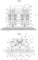
- the track construction machine 1 shown is designed as a track tamping machine for tamping sleepers 4 stored in a ballast bed 2 of a track 3.
- the track construction machine 1 comprises a machine frame 6 supported on rail carriages 5, on which a tamping unit 7 is arranged. By means of this tamping unit 7, a group of several adjacent sleepers 4 can be tamped during a tamping process.
- the track construction machine 1 comprises a lifting and straightening unit 8 for lifting and straightening the track grid formed from sleepers 4 and rails 9. A current rail position is recorded using a measuring system 10.
- the tamping unit 7 is attached to the machine frame 6 by means of an adjusting device 11. It comprises an unit frame 12 with guides 13. A tool carrier 14 is mounted on the guides 13 so that its height can be adjusted by means of a height adjustment drive 15. Several tamping tools 17 are mounted on the tool carrier 14 one behind the other with respect to a working direction 16 about a respective pivot axis 18. The adjacent pivot axes 18 are spaced apart from one another by a distance a that approximates a sleeper pitch t of the track 3 to be tamped.
- Each tamping tool 17 comprises a pivot lever 19 with an upper and a lower lever arm with respect to the associated pivot axis 17. At least one tamping pick 20 is arranged on the lower lever arm. Preferably, two tamping picks 20 are fastened next to one another in a tamping pick holder 21 of the respective tamping tool 17.
- the upper lever arm is connected in an articulated manner to a first end of an auxiliary drive 22.
- a second end of the auxiliary drive 22 is mounted on an eccentric shaft 23 of a vibration drive 24.
- the respective auxiliary drive 22 is preferably a hydraulic cylinder which is connected to a hydraulic system of the track construction machine 1.
- auxiliary drives 22 of the tamping tools 17 arranged one behind the other are mounted on the same eccentric shaft 23.
- each auxiliary drive 22 is mounted on an associated eccentric shaft section with its own eccentricity.
- An adjustable sleeve is mounted on each of these eccentric shaft sections in order to adjust the respective eccentricity.
- a corresponding mechanism is shown in the AT 517999 A1 described.
- the respective adjustment drive 22 is attached directly to the tool carrier 14 and is designed to simultaneously generate a vibration and an adjustment movement 25.
- the vibration can be switched on and off at any time.
- Another possibility is to suspend the vibration transmission of the eccentric shaft 23 by depressurizing the respective auxiliary drive 22. The associated tamping tool 17 immersed in the ballast bed 2 is then held in position by the adjacent ballast.
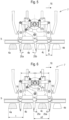
- Fig.2 shows the tamping unit 7 in a form with four tamping tools 17h, 17m1, 17m2, 17v arranged one behind the other.
- two middle tamping tools 17m1, 17m2 are arranged between the rearmost tamping tool 17h and the frontmost tamping tool 17v.
- the arrangement of the four tamping tools 17h, 17m1, 17m2, 17v is symmetrical with respect to a plane of symmetry 26 running perpendicular to the working direction 16.
- the respective auxiliary drive 22a of the frontmost 17v and the rearmost tamping tool 17h is only designed for one auxiliary movement 25a.
- the corresponding auxiliary drive 22a is extended so that the associated tamping picks 20 are auxiliary in the direction of the middle tamping tools 17m1, 17m2.
- the respective auxiliary drive 22b of the middle tamping tools 17m1, 17m2 is designed for a first tamping movement 25b and for an opposite second tamping movement 25c. Both the extension and the retraction of the respective auxiliary drive 22b causes a corresponding tamping movement 25b, 25c.
- the associated tamping picks 20 have pick plates with two working surfaces 27 facing away from each other, by means of which the ballast can be mobilized in both directions. In this way, the middle tamping tools 17m1, 17m2 can be used to tamper both the sleeper 4 positioned in front of and behind it.
- each of these four rows of tamping tools is solely designed for immersion in a currently assigned sleeper intermediate compartment 28.
- the respective drives 15, 22, 24 are coupled to a control device 29. This allows, for example, the vibration of a respective tamping tool 17 to be switched on and off.
- FIG.4 A variant of the tamping unit 7 with three tamping tools 17h, 17m, 17v arranged one behind the other is shown in Fig.4 shown.
- only one middle tamping tool 17m is designed between the frontmost 17v and the rearmost tamping tool 17h for two positioning movements 25b, 25c in opposite directions.
- the frontmost 17v and the rearmost tamping tool 17h are arranged symmetrically with respect to the plane of symmetry 26 running perpendicular to the working direction 16.
- the upper lever arm of the middle tamping tool 17m is bent backwards relative to the lower lever arm, so that extending and retracting the associated positioning drive 22b causes a pivoting movement about the associated pivot axis 18.
- tamping tools 17h, 17m, 17v are subjected to vibration.
- Fig.4 shows the tamping tools 17h, 17m, 17v immediately after immersion in the ballast bed 2 for tamping the second 4b and the third sleeper 4c of the four sleepers 4a-4d shown.
- the first sleeper 4a was already tamped during the previous tamping cycle. This tamping is marked by hatching.
- the tamping pick tips of the rearmost 17h and the middle tamping tool 17m are set to a first opening width o1, which is larger than the sleeper pitch t.
- the middle tamping tool 17m thus immerses itself in the ballast bed 2 in the area between an intermediate compartment center 30 and the adjacent sleeper 4c. In this way, it is ensured that with both subsequent positioning movements 25b, 25c approximately the same amount of ballast is pushed under the respective sleeper 4. Accordingly, evenly compacted ballast cushions form under all tamped sleepers 4.
- the opening width o1 corresponds to the threshold pitch t plus an expected adjustment path.
- the rearmost 17h and the middle tamping tool 17m form a first group, which are provided first.
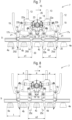
- the corresponding process for tamping the second sleeper 4b shown is shown in Fig.5 shown.
- the positioning drive 22a of the rear tamping tool 17h is extended and the positioning drive 22b of the middle tamping tool 17m is retracted.
- This is preferably done with the same system pressure, with the piston surfaces being coordinated with one another so that both tamping tools 17h, 17m exert the same positioning force on the ballast.
- the corresponding tamping tools 17h, 17m are subjected to vibration in order to further compact the ballast pushed under the sleeper 4b.
- the vibration is preferably switched off during this time.
- the middle tamping tool 17m uses almost the entire width b of the sleeper intermediate compartment 28.
- the tamping pick tips of the middle 17m and the front tamping tool 17v have a second opening width o2, which essentially corresponds to the first opening width o1 ( Fig.6 ).
- the third sleeper 4c shown is tamped by the second tamping process, for which the middle 17m and the front tamping tool 17v form a second group.
- the front tamping tool 17v is moved with the intended tamping movement 17a in the direction of the middle tamping tool 17m.
- the tamping drive 22b of the middle tamping tool 17m is extended, resulting in the second tamping movement 25c in the direction of the front tamping tool 17v.
- a second system pressure is applied in order to take into account the surface difference between the piston surface and the ring surface of the hydraulic cylinder.
- the system pressures and the piston and ring surfaces are coordinated so that all tamping tools 17h, 17m, 17v exert the same tamping force on the ballast.
- both the frontmost 17v and the middle tamping tool 17m are subjected to vibration.
- the rearmost tamping tool 17h remains in a reset position without vibration in order not to affect the sleeper support of the already tamped sleeper 4b.
- all tamping tools 17h, 17m, 17v are pulled out of the ballast bed 2 together, with the middle 17m and the frontmost tamping tool 17v being returned to the starting position with the first opening width o1.
- the tamping unit 7 then moves forward in the working direction 16 to the next two sleepers 4 to be tamped.
- the Figures 7 and 8 show a corresponding sequence with four tamping tools 17h, 17m1, 17m2, 17v arranged one behind the other.
- three of the five sleepers 4b-4e shown are tamped.
- the first sleeper 4a shown was already tamped beforehand.
- All four tamping tools 17h, 17m1, 17m2, 17v are subjected to vibration during an immersion process and form the first group for the first positioning process. Starting from an immersion position with a first opening width o1, the rearmost 17h and the first middle tamping tool 17m1 as well as the frontmost 17v and the second middle tamping tool 17m2 are placed next to each other.
- All tamping tools 17h, 17m1, 17m2, 17v are subjected to vibration.
- the auxiliary drives 22a are extended on the rearmost 17h and the frontmost tamping tool 17v.
- the auxiliary drives 22b of the middle tamping tools 17m1, 17m2 are retracted.
- the auxiliary hydraulic cylinders are subjected to a first system pressure.
- the second 4b and the fourth sleeper 4d are completely stuffed and the two middle stuffing tools 17m1, 17m2 have a second opening width o2 that is slightly larger than the first opening width o1. This means that almost the entire width of the intermediate compartment b can be used for the second positioning movement.
- the second positioning process takes place with the second tamping movement 25c of the middle tamping tools 17m1, 17m2 in the opposite direction. Only the middle tamping tools 17m1, 17m2 are subjected to vibration so that the sleeper supports of the already tamped sleepers 4b, 4d are not affected.
- the associated tamping drives 22b are extended, and in the case of tamping hydraulic cylinders, a second system pressure is applied.
- the first and second system pressures are coordinated in such a way that all tamping tools 17h, 17m1, 17m2, 17v exert the same tamping force on the ballast during the respective tamping process.
- the result of the second tamping process is the tamping of the third sleeper 4c. All tamping tools 17h, 17m1, 17m2, 17v are then raised and reset. After a forward movement of the tamping unit 7 in the working direction 16 by three times the sleeper pitch 3 t, the next tamping cycle begins.
- Fig.9 shows an alternative working method of the tamping unit 7 with four tamping tools 17h, 17m1, 17m2, 17v arranged one behind the other.
- the tamping unit 7 is moved forwards alternately by the sleeper pitch t and by three times the sleeper pitch 3 ⁇ t in the working direction 16. In this way, two sleepers 4 are tamped during each tamping process, with a sleeper 4 being located between these sleepers 4.
- This alternative working method is particularly gentle on the ballast and on the tamping unit 7. It is best used at track sections with difficult conditions.
- One advantage of the tamping unit 7 with four tamping tools 17h, 17m1, 17m2, 17v arranged one behind the other is the ability to carry out both this alternative working method and the previously described working method for tamping all three sleepers during one tamping process.
Landscapes
- Engineering & Computer Science (AREA)
- Architecture (AREA)
- Civil Engineering (AREA)
- Structural Engineering (AREA)
- Machines For Laying And Maintaining Railways (AREA)
Applications Claiming Priority (1)
| Application Number | Priority Date | Filing Date | Title |
|---|---|---|---|
| AT510092022 | 2022-12-30 |
Publications (3)
| Publication Number | Publication Date |
|---|---|
| EP4403701A1 true EP4403701A1 (fr) | 2024-07-24 |
| EP4403701B1 EP4403701B1 (fr) | 2025-08-13 |
| EP4403701C0 EP4403701C0 (fr) | 2025-08-13 |
Family
ID=89386252
Family Applications (1)
| Application Number | Title | Priority Date | Filing Date |
|---|---|---|---|
| EP23220307.5A Active EP4403701B1 (fr) | 2022-12-30 | 2023-12-27 | Unité de bourrage et procédé de bourrage d'un groupe de traverses adjacentes d'une voie ferrée |
Country Status (2)
| Country | Link |
|---|---|
| EP (1) | EP4403701B1 (fr) |
| AT (1) | AT18243U1 (fr) |
Families Citing this family (1)
| Publication number | Priority date | Publication date | Assignee | Title |
|---|---|---|---|---|
| AT523825B1 (de) * | 2020-07-03 | 2021-12-15 | Plasser & Theurer Export Von Bahnbaumaschinen Gmbh | Maschine und Verfahren mit einem Stopfaggregat |
Citations (6)
| Publication number | Priority date | Publication date | Assignee | Title |
|---|---|---|---|---|
| US3589297A (en) * | 1968-04-29 | 1971-06-29 | Plasser Bahnbaumasch Franz | Track-tamping assembly |
| EP0775779A1 (fr) | 1995-11-22 | 1997-05-28 | Franz Plasser Bahnbaumaschinen-Industriegesellschaft m.b.H. | Unité de bourrage |
| AT517999A1 (de) | 2015-11-20 | 2017-06-15 | Plasser & Theurer Export Von Bahnbaumaschinen Gmbh | Stopfaggregat und Verfahren zum Stopfen eines Gleises |
| EP3207179B1 (fr) * | 2014-10-17 | 2019-02-20 | Plasser & Theurer Export von Bahnbaumaschinen Gesellschaft m.b.H. | Machine de bourrage pour bourrer des traverses d'une voie ferrée |
| EP3237681B1 (fr) * | 2014-12-22 | 2019-07-24 | HP3 Real GmbH | Unité de bourrage destinée à une bourreuse de traverses |
| EP3545134B1 (fr) * | 2016-11-25 | 2020-09-16 | Plasser & Theurer Export Von Bahnbaumaschinen Gesellschaft m.b.H. | Groupe de bourrage pour bourrage des traverses d'une voie ferrée |
Family Cites Families (3)
| Publication number | Priority date | Publication date | Assignee | Title |
|---|---|---|---|---|
| RU2194108C2 (ru) * | 2000-05-31 | 2002-12-10 | Центральное Конструкторское Бюро Тяжелых Путевых Машин | Шпалоподбивочная машина |
| AT500972B1 (de) * | 2004-10-29 | 2006-05-15 | Plasser Bahnbaumasch Franz | Verfahren zum unterstopfen von schwellen |
| AT524276B1 (de) * | 2020-09-16 | 2025-04-15 | Plasser & Theurer Export Von Bahnbaumaschinen Gmbh | Verfahren und Gleisstopfmaschine zum Unterstopfen eines Gleises |
-
2022
- 2022-12-30 AT ATGM8045/2023U patent/AT18243U1/de unknown
-
2023
- 2023-12-27 EP EP23220307.5A patent/EP4403701B1/fr active Active
Patent Citations (6)
| Publication number | Priority date | Publication date | Assignee | Title |
|---|---|---|---|---|
| US3589297A (en) * | 1968-04-29 | 1971-06-29 | Plasser Bahnbaumasch Franz | Track-tamping assembly |
| EP0775779A1 (fr) | 1995-11-22 | 1997-05-28 | Franz Plasser Bahnbaumaschinen-Industriegesellschaft m.b.H. | Unité de bourrage |
| EP3207179B1 (fr) * | 2014-10-17 | 2019-02-20 | Plasser & Theurer Export von Bahnbaumaschinen Gesellschaft m.b.H. | Machine de bourrage pour bourrer des traverses d'une voie ferrée |
| EP3237681B1 (fr) * | 2014-12-22 | 2019-07-24 | HP3 Real GmbH | Unité de bourrage destinée à une bourreuse de traverses |
| AT517999A1 (de) | 2015-11-20 | 2017-06-15 | Plasser & Theurer Export Von Bahnbaumaschinen Gmbh | Stopfaggregat und Verfahren zum Stopfen eines Gleises |
| EP3545134B1 (fr) * | 2016-11-25 | 2020-09-16 | Plasser & Theurer Export Von Bahnbaumaschinen Gesellschaft m.b.H. | Groupe de bourrage pour bourrage des traverses d'une voie ferrée |
Also Published As
| Publication number | Publication date |
|---|---|
| EP4403701B1 (fr) | 2025-08-13 |
| AT18243U1 (de) | 2024-06-15 |
| EP4403701C0 (fr) | 2025-08-13 |
Similar Documents
| Publication | Publication Date | Title |
|---|---|---|
| AT500972B1 (de) | Verfahren zum unterstopfen von schwellen | |
| EP0726360B1 (fr) | Procédé et machine pour le bourrage et l'assainissement d'une voie ferrée | |
| EP0518845B1 (fr) | Méthode et machine de compactage de ballast pour voies ferrées | |
| DE3819717C2 (de) | Kontinuierlich verfahrbare Gleisbaumaschine | |
| DD292492A5 (de) | Fahrbare gleisstopf-, nivellier- und richtmaschine | |
| EP2912226B1 (fr) | Procédé pour bourrer une voie ferrée par des dispositifs de bourrage commandés d'une façon asynchrone | |
| AT391904B (de) | Gleisbaumaschine mit gleis-stabilisator | |
| EP0633355A2 (fr) | Machine de balayage d'une voie ferrée | |
| AT522456B1 (de) | Stopfaggregat zum Unterstopfen von Schwellen eines Gleises | |
| DE2605969A1 (de) | Fahrbare maschine zum verdichten und korrigieren des gleises | |
| EP4403701B1 (fr) | Unité de bourrage et procédé de bourrage d'un groupe de traverses adjacentes d'une voie ferrée | |
| EP4214363A1 (fr) | Procédé et machine de bourrage de voie pour le bourrage d'une voie | |
| DE2348014A1 (de) | Verfahren und vorrichtung zum richten und nivellieren von eisenbahngleisen | |
| EP4323587B1 (fr) | Procédé et machine de bourrage d'une voie | |
| DE2602161A1 (de) | Gleisstopfmaschine | |
| EP4176132A1 (fr) | Procédé et machine comprenant un ensemble de tassement | |
| DE69708467T2 (de) | Selbstfahrende Maschine für die Verdichtung und Schlag-Stabilisierung von Gleisanlagen auf Schotter | |
| EP3938578B1 (fr) | Procédé pour compacter un lit de ballast d'une voie ferrée | |
| DE2550382A1 (de) | Verfahren und vorrichtung zum gleisrichten und bettungsschulterverdichten | |
| EP4176133B1 (fr) | Procédé et machine de bourrage d'une voie | |
| DE3132870C2 (de) | Gleisstopf-,Nivellier- und Richtmaschine mit Gleis-Stabilisationsaggregat | |
| EP1069240B1 (fr) | Procédé de bourrage | |
| DD285391A5 (de) | Gleisstopfmaschine | |
| DE2602160A1 (de) | Gleisstopfmaschine mit vorkopfverdichter | |
| DE2608372C2 (de) | Fahrbare Gleisbaumaschine zum Verdichten des Schotters unterhalb der Schwellen eines Gleises |
Legal Events
| Date | Code | Title | Description |
|---|---|---|---|
| PUAI | Public reference made under article 153(3) epc to a published international application that has entered the european phase |
Free format text: ORIGINAL CODE: 0009012 |
|
| STAA | Information on the status of an ep patent application or granted ep patent |
Free format text: STATUS: THE APPLICATION HAS BEEN PUBLISHED |
|
| AK | Designated contracting states |
Kind code of ref document: A1 Designated state(s): AL AT BE BG CH CY CZ DE DK EE ES FI FR GB GR HR HU IE IS IT LI LT LU LV MC ME MK MT NL NO PL PT RO RS SE SI SK SM TR |
|
| STAA | Information on the status of an ep patent application or granted ep patent |
Free format text: STATUS: REQUEST FOR EXAMINATION WAS MADE |
|
| 17P | Request for examination filed |
Effective date: 20250124 |
|
| GRAP | Despatch of communication of intention to grant a patent |
Free format text: ORIGINAL CODE: EPIDOSNIGR1 |
|
| STAA | Information on the status of an ep patent application or granted ep patent |
Free format text: STATUS: GRANT OF PATENT IS INTENDED |
|
| INTG | Intention to grant announced |
Effective date: 20250320 |
|
| GRAS | Grant fee paid |
Free format text: ORIGINAL CODE: EPIDOSNIGR3 |
|
| GRAA | (expected) grant |
Free format text: ORIGINAL CODE: 0009210 |
|
| STAA | Information on the status of an ep patent application or granted ep patent |
Free format text: STATUS: THE PATENT HAS BEEN GRANTED |
|
| AK | Designated contracting states |
Kind code of ref document: B1 Designated state(s): AL AT BE BG CH CY CZ DE DK EE ES FI FR GB GR HR HU IE IS IT LI LT LU LV MC ME MK MT NL NO PL PT RO RS SE SI SK SM TR |
|
| REG | Reference to a national code |
Ref country code: GB Ref legal event code: FG4D Free format text: NOT ENGLISH |
|
| REG | Reference to a national code |
Ref country code: CH Ref legal event code: EP |
|
| REG | Reference to a national code |
Ref country code: DE Ref legal event code: R096 Ref document number: 502023001581 Country of ref document: DE |
|
| REG | Reference to a national code |
Ref country code: IE Ref legal event code: FG4D Free format text: LANGUAGE OF EP DOCUMENT: GERMAN |
|
| U01 | Request for unitary effect filed |
Effective date: 20250820 |
|
| U07 | Unitary effect registered |
Designated state(s): AT BE BG DE DK EE FI FR IT LT LU LV MT NL PT RO SE SI Effective date: 20250828 |