EP4402324B1 - Vorgefertigte gebäudestruktur - Google Patents
Vorgefertigte gebäudestruktur Download PDFInfo
- Publication number
- EP4402324B1 EP4402324B1 EP22754958.1A EP22754958A EP4402324B1 EP 4402324 B1 EP4402324 B1 EP 4402324B1 EP 22754958 A EP22754958 A EP 22754958A EP 4402324 B1 EP4402324 B1 EP 4402324B1
- Authority
- EP
- European Patent Office
- Prior art keywords
- pillar
- protrusion
- support
- structure according
- slot
- Prior art date
- Legal status (The legal status is an assumption and is not a legal conclusion. Google has not performed a legal analysis and makes no representation as to the accuracy of the status listed.)
- Active
Links
Images


Classifications
-
- E—FIXED CONSTRUCTIONS
- E04—BUILDING
- E04B—GENERAL BUILDING CONSTRUCTIONS; WALLS, e.g. PARTITIONS; ROOFS; FLOORS; CEILINGS; INSULATION OR OTHER PROTECTION OF BUILDINGS
- E04B1/00—Constructions in general; Structures which are not restricted either to walls, e.g. partitions, or floors or ceilings or roofs
- E04B1/18—Structures comprising elongated load-supporting parts, e.g. columns, girders, skeletons
- E04B1/20—Structures comprising elongated load-supporting parts, e.g. columns, girders, skeletons the supporting parts consisting of concrete, e.g. reinforced concrete, or other stonelike material
- E04B1/21—Connections specially adapted therefor
- E04B1/215—Connections specially adapted therefor comprising metallic plates or parts
Definitions
- the present invention relates to a prefabricated building structure.
- the technical task underpinning the present invention is to provide a prefabricated building structure which obviates the drawbacks of the prior art as described above.
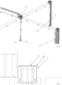
- reference number 1 indicates a prefabricated building structure.
- it is a prefabricated building structure in concrete.
- Such a building structure therefore defines a building. It is of the prefabricated type and therefore the assembly of previously-made structural elements occurs on site.
- Such a building structure 1 comprises a first and a second pillar 21, 22.
- the first and the second pillar 21, 22 are reciprocally stacked. They have a preponderant longitudinal extension direction.
- the first and the second pillar 21, 22 extend preponderantly vertically. They are also stacked vertically.
- An upper end 211 of the first pillar 21 is located at a lower end 221 of the second pillar 22.
- the upper end 211 and the lower end 221 are facing each other.
- the upper end 211 of the first pillar 21 and the lower end 221 of the second pillar 22 are in reciprocal contact.
- the first pillar 21 is below the second pillar 22.
- the structure 1 comprises a beam 3 extending substantially horizontally and has a first end 31 located at said upper end 211 and said lower end 221.
- the first pillar 21 and/or the second pillar 22 and/or the beam 3 is/are made of concrete.
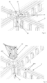
- the structure 1 comprises reciprocal fixing means 9 for reciprocally fixing the first pillar 21, the second pillar 22 and the beam 3 (see for example figures 9 and 10 ).
- the reciprocal fixing means 9 can be at least partly incorporated in the first pillar 21, in the second pillar 22, in the beam 3.
- the first pillar 21, the second pillar 22 and the beam 3 define a junction area defining a node.
- several beams can lie on the same node (such beams are typically transverse, in particular orthogonal to one another; suitably they lie on the same horizontal plane).
- the first and the second pillar 21, 22 can therefore be in common between several incident vertical walls.
- the node is therefore a three-dimensional node.
- the node defines a hyperstatic joint.
- the reciprocal fixing means 9 comprises projecting means 91 and corresponding housing means 92 in which the projecting means 91 fits defining a joint (see for example figures 9 and 10 ).
- the projecting means 91 and the housing means 92 are suitably counter-shaped. There can be a minimum clearance (for example a few millimetres) to facilitate insertion.
- the projecting means 91 and the housing means 92 define male-female connections both between the first pillar 21 and the beam 3 and between the second pillar 22 and the beam 3.
- the projecting means 91 is obtained on both the first pillar 21 and on the second pillar 22. It fits in corresponding housing means 92 obtained on the beam 3.
- the projecting means 91 (solution not shown) is obtained on the beam 3 while the housing means 92 is obtained on both the first and on the second pillar 21, 22.
- the projecting means 91 is obtained partly on the beam 3 and partly on the first pillar 21 while the housing means 92 is obtained partly on the beam 3 and partly on the second pillar 22.
- the projecting means 91 is obtained partly on the beam 3 and partly on the second pillar 22 while the housing means 92 is obtained partly on the beam 3 and partly on the first pillar 21.
- the projecting means 91 comprises:
- the first and the second protrusion 213, 223 project transversally with respect to the preponderant longitudinal extension direction 20.
- the first and the second protrusion 213, 223 project horizontally. They can define flaps.
- the housing means 92 comprises at a first end 31 of the beam 3 a slot 30.
- the first and the second protrusion 213, 223 at least partially fit in the slot 30 at the first end 31.
- first and the second protrusion 213, 223 could fit in different slots of the beam 3.
- the first pillar 21 comprises:
- the first element 215 is an angle profile comprising:
- first and the second element 215, 225 are not reciprocally in contact in the slot 30. They contact at least opposite surfaces of the slot 30.
- first and the second element 215, 225 there are interposed end plates 218 of the first and the second pillar 21, 22 which extend transversally to the preponderant extension direction 20.
- the first protrusion 213 protrudes with respect to the first support 214 along a direction transverse (preferably orthogonal) to the direction 20 of greater extension of the first pillar 21.
- the structure 1 also comprises threaded connecting means 4 which connects the first element 215 (or in any case the first protrusion 213) and the first support 214.
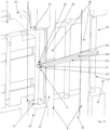
- the solution of figures 1-9 are schematically represented in figure 7 .
- the means 4 is not displayed as it is hidden, but it is vertical screws which connect the first plate element 215 with the first pillar 21.
- the first support 214 advantageously comprises at least one threaded housing forming part of the means 4; the first element 215 suitably comprises a through hole.
- the threaded connecting means 4 comprises at least a first screw 41 (advantageously a plurality of screws) which connects the first element 215 (and thus the first protrusion 213) to the first support 214.
- the first screw 41 transits in said through hole and comprises a threaded body which fits in said threaded housing.
- the threaded connecting means 4 comprises a plurality of screws which transit in corresponding through holes of the first element 215 and fit in corresponding threaded housings of the first support 214.
- the second pillar 22 comprises:
- the second element 225 is a head plate of the second support 224 (thus of the second pillar 22). Such a plate is horizontal.
- the second protrusion 223 is an edge of the plate.
- the head plate (corresponding to the first element 215) of the first support 214 and the head plate (corresponding to the second element 225) of the second support 224 fit in both the slot 30 of the beam 3, but also in at least one other slot obtained on another of said incident beams (suitably each incident beam has its own slot in which the aforementioned head plates fit).
- Different peripheral edges of said head plates fit in the different slots.
- such plates could be quadrilateral/polygonal and a first side of the quadrilateral fits in the slot 30 and a second side fits in a slot of another beam.
- the second element 225 is an angle profile comprising:
- the slot 30 has a preponderant extension direction.
- the slot 30 extends horizontally.
- the slot 30 extends in width orthogonally to said preponderant longitudinal direction.
- the first and the second protrusion 213, 223 are superposed one on the other and are joined in the width of the slot 30.
- the thickness of the first protrusion 213 added to the thickness of the second protrusion 223 is equal to the width of the slot 30.
- the slot 30 accommodates only a peripheral flap of both the first and the second protrusion 213, 223.
- the beam 3 comprises an end plate 35 in which the slot 30 is obtained.
- the plate 35 is located in the first end 31.
- the beam 3 (in particular the plate 35) comprises a plurality of holes 34; the structure 1 advantageously comprises threaded joining means 5 which crosses said holes 34 and inserts in threaded counter-shapings made in the first and the second pillar 21, 22.
- the joining means 5 comprises a plurality of threaded elements which insert in the corresponding holes 34 and in the corresponding threaded counter-shapings.
- the threaded joining means 5 is stressed by pure traction. There are thus no shear loads.
- the means 4 and the means 5 coincide. In the solution of figure 10 , they are instead distinct.
- the structure 1 comprises enveloping means 8 which compresses said first pillar 21. It suitably exerts a post compression by winding. Thereby, the post-compression load can also be applied to the reciprocal fixing means 9.
- the enveloping means 8 compresses the first pillar 21 along the longitudinal extension direction.
- the enveloping means 8 overlaps two opposite ends of the first pillar 21.
- the enveloping means 8 can comprise a first enveloping 81 which transits in two bases and two opposite lateral flanks of the first pillar 21.
- the enveloping means 8 can comprise a second enveloping which affects the two bases and two further lateral flanks (distinct from the two mentioned just above) of the first pillar 21.
- the enveloping means 8 can pass between the plate of the first element 215 and the first support 214.
- the enveloping means 8 advantageously comprises a fibre-resin structure.
- it is a band.
- the fibre is a glass fibre or a carbon fibre or a basalt fibre.
- it is inert to corrosion and chemical attacks so that the durability of the elements is greatly increased.
- the resin for example, can be a polyester, vinyl ester, epoxy, polyurethane resin.
- the structure 1 can comprise enveloping means 80 which compresses the second pillar 22 (preferably along a preponderant extension direction).
- the structure 1 can comprise enveloping means 800 which compresses the beam 3 (preferably along a preponderant extension of the beam 3).
- the first pillar 21, the second pillar 22 and the horizontal beam 3 are dry-connected without welds on site. They are also connected without having to make use of welds on site.
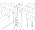
- the structure 1 comprises a wall 6 which lies in the plane identified by the first pillar 21 and by the beam 3.
- a wall 6 is suitably vertical.
- it is made of concrete.
- the wall 6 advantageously occludes (at least in part, preferably all) the space interposed between the first pillar 21 and the beam 3.
- the first pillar 21 has a lateral flank comprising parallel lateral flanks 62 which extend longitudinally along the preponderant direction 20 to house a portion of the wall 6.
- the first pillar 21 has a quadrilateral shape and at each vertex of the quadrilateral it has longitudinal sides 62 which define four channels 63, one per flank.
- the four channels 63 are intended to house at least one portion of a corresponding wall.
- the building structure 1 is modular. In particular, it comprises a plurality of pillars, beams, walls assembled together.
- the first pillar 21 can advantageously also be repeated for the second pillar 22.
- the first pillar 21 is identical to the second pillar 22.
- the building structure 1 can be completed in the desired geometry, exploiting the modularity of the elements.
- the method comprises the step of inserting the first and the second protrusion 213, 223 in the slot 30, introducing two corresponding angle profiles comprising respectively the first and the second protrusion 213, 223 in cavities 64 which are between the first and the second pillar 21, 22 and the beam 3 already in position.
- the present invention achieves important advantages.
- the nodes thus defined allow the transfer of very high specific moments without having to resort to connection casts or welds on site.
- prefabricated elements pillars, beams
- the vertical loads supported by the horizontal beams can be transferred as compression and shear on the pillars. There are no shear loads on the screws.
- the structure 1 can be incorporated with the post-compression and thereby the post-compression load is also applied to the fixing elements.
Landscapes
- Engineering & Computer Science (AREA)
- Architecture (AREA)
- Physics & Mathematics (AREA)
- Electromagnetism (AREA)
- Civil Engineering (AREA)
- Structural Engineering (AREA)
- Joining Of Building Structures In Genera (AREA)
- Load-Bearing And Curtain Walls (AREA)
Claims (9)
- Vorgefertigte Gebäudestruktur, umfassend:- einen ersten und einen zweiten Stützpfeiler (21, 22), die aufeinander gestapelt sind und eine vorwiegende Längsausdehnungsrichtung (20) aufweisen,wobei ein oberes Ende (211) des ersten Stützpfeilers (21) an einem unteren Ende (221) des zweiten Stützpfeilers (22) befindlich ist;- einen Träger (3), der sich im Wesentlichen horizontal erstreckt und ein erstes Ende (31) aufweist, das am oberen Ende (211) und am unteren Ende (221) befindlich ist;- gegenseitige Fixiermittel (9) zum gegenseitigen Fixieren des ersten Stützpfeilers (21), des zweiten Stützpfeilers (22) und des Trägers (3), wobei die gegenseitigen Fixiermittel (9) mindestens teilweise in den ersten Stützpfeiler (21), in den zweiten Stützpfeiler (22), in den Träger (3) integriert werden können,wobei die gegenseitigen Fixiermittel (9) auskragende Mittel (91) und entsprechende Aufnahmemittel (92) umfassen, in die die auskragenden Mittel (91) eingepasst sind und einen Anschluss definieren,wobei die auskragenden Mittel (91) und die Aufnahmemittel (92) Nut-Feder-Verbindungen sowohl zwischen dem ersten Stützpfeiler (21) und dem Träger (3) als auch zwischen dem zweiten Stützpfeiler (22) und dem Träger (3) definieren,dadurch gekennzeichnet, dass- die Struktur Umfassungsmittel (8) umfasst, die den ersten Stützpfeiler (21) entlang der vorwiegenden Längsausdehnungsrichtung (20) komprimieren, wobei die Umfassungsmittel (8) eine Nachkomprimierung durch Umspannen ausüben, wobei die Umfassungsmittel (8) eine Faser-Harz-Struktur umfassen;- der erste Stützpfeiler (21), der zweite Stützpfeiler (22) und der horizontale Träger (3) in Trockenbauweise ohne Schweißen und ohne Verbindungsgüsse verbunden sind.
- Struktur nach Anspruch 1, dadurch gekennzeichnet, dass die auskragenden Mittel (91) Folgendes umfassen:- eine erste Auskragung (213), die am oberen Ende (211) befindlich und mit dem ersten Stützpfeiler (21) assoziiert ist;- eine zweite Auskragung (223), die am unteren Ende (221) befindlich und mit dem zweiten Stützpfeiler (22) assoziiert ist,wobei die erste und die zweite Auskragung (213, 223) quer in Bezug auf die vorwiegende Längsausdehnungsrichtung (20) auskragen,wobei die Aufnahmemittel (92) am ersten Ende (31) des Trägers (3) einen Schlitz (30) umfassen,wobei die erste und die zweite Auskragung (213, 223) mindestens teilweise in den Schlitz (30) am ersten Ende (31) eingepasst sind.
- Struktur nach Anspruch 2, dadurch gekennzeichnet, dass der erste Stützpfeiler (21) Folgendes umfasst:- ein erstes Element (215), umfassend die erste Auskragung (213);- eine erste Stütze (214), mit der das erste Element (215) entfernbar verbunden ist,wobei der zweite Stützpfeiler (22) Folgendes umfasst:i) ein zweites Element (225), das die zweite Auskragung (223) umfasst;ii) eine zweite Stütze (224), mit der das zweite Element (225) entfernbar verbunden ist.
- Struktur nach Anspruch 3, dadurch gekennzeichnet, dass das erste Element (215) eine stirnseitige Platte der ersten Stütze (214) ist und das zweite Element (225) eine stirnseitige Platte der zweiten Stütze (224) ist.
- Struktur nach Anspruch 4, dadurch gekennzeichnet, dass die Umfassungsmittel (8) zwischen der Platte des ersten Elements (215) und der ersten Stütze (214) hindurchführen.
- Struktur nach Anspruch 3, dadurch gekennzeichnet, dass das erste Element (215) ein Winkelprofil ist, umfassend:- einen ersten Arm (216), der mit der ersten Stütze (214) entlang einer seitlichen Flanke (219) der ersten Stütze (214) verbunden ist;- einen zweiten Arm (217), der wegführend von der ersten Stütze (214) auskragt und in dem die erste Auskragung (213) ausgebildet ist,wobei das zweite Element (225) ein Winkelprofil ist, umfassend:i) einen ersten Abschnitt (226), der seitlich mit der zweiten Stütze (224) verbunden ist;ii) einen zweiten Abschnitt (227), der wegführend von der zweiten Stütze (224) auskragt und in dem die zweite Auskragung (223) ausgebildet ist.
- Struktur nach einem der Ansprüche 2-6, dadurch gekennzeichnet, dass der Schlitz (30) eine vorwiegende Längsrichtung aufweist und sich in der Breite rechtwinkelig zur vorwiegenden Ausdehnungsrichtung erstreckt, wobei die erste und die zweite Auskragung (213, 223) einander überlagern und in der Breite des Schlitzes (30) zusammengefügt sind.
- Struktur nach einem der vorhergehenden Ansprüche, dadurch gekennzeichnet, dass der Träger (3) eine Vielzahl von Löchern (34) umfasst, wobei die Struktur Gewindezusammenfügungsmittel (5) umfasst, die die Löcher (34) kreuzen und die in gegenständige Gewindeausformungen eingefügt sind, die im ersten und im zweiten Stützpfeiler (21, 22) ausgebildet sind, wobei die Gewindezusammenfügungsmittel (5) durch reinen Zug beansprucht werden.
- Struktur nach einem der vorhergehenden Ansprüche, dadurch gekennzeichnet, dass sie eine vertikale Betonwand (6) umfasst, die in der durch den ersten Stützpfeiler (21) und den Träger (3) identifizierten Ebene liegt und die den zwischen dem ersten Stützpfeiler (21) und dem Träger (3) eingefügten Raum verschließt.
Applications Claiming Priority (2)
| Application Number | Priority Date | Filing Date | Title |
|---|---|---|---|
| IT202100023723 | 2021-09-15 | ||
| PCT/IB2022/057311 WO2023042003A1 (en) | 2021-09-15 | 2022-08-05 | Prefabricated building structure |
Publications (3)
| Publication Number | Publication Date |
|---|---|
| EP4402324A1 EP4402324A1 (de) | 2024-07-24 |
| EP4402324B1 true EP4402324B1 (de) | 2025-04-02 |
| EP4402324C0 EP4402324C0 (de) | 2025-04-02 |
Family
ID=78770996
Family Applications (1)
| Application Number | Title | Priority Date | Filing Date |
|---|---|---|---|
| EP22754958.1A Active EP4402324B1 (de) | 2021-09-15 | 2022-08-05 | Vorgefertigte gebäudestruktur |
Country Status (6)
| Country | Link |
|---|---|
| US (1) | US12378760B2 (de) |
| EP (1) | EP4402324B1 (de) |
| AU (1) | AU2022346238A1 (de) |
| CA (1) | CA3230070A1 (de) |
| MX (1) | MX2024003281A (de) |
| WO (1) | WO2023042003A1 (de) |
Family Cites Families (104)
| Publication number | Priority date | Publication date | Assignee | Title |
|---|---|---|---|---|
| US2100451A (en) * | 1935-04-10 | 1937-11-30 | Nat Parkhurst Systems Inc | Building construction |
| NL296773A (de) * | 1962-08-17 | |||
| GB1150871A (en) * | 1965-02-16 | 1969-05-07 | Componoform Inc | Improvement in and relating to Building Construction and Pre-Fabricated Components Therefor |
| GB1163537A (en) * | 1966-02-26 | 1969-09-10 | Trent Concrete Ltd | Improvements in and relating to precast reinforced, concrete structural members |
| US3429092A (en) * | 1966-05-26 | 1969-02-25 | Dyna Structures | Structural frames and methods and means therefor |
| IE31993B1 (en) * | 1968-03-22 | 1973-03-07 | Clyne Hugh Mary | Improvements in reinforced concrete building frame construction |
| US3594971A (en) * | 1969-06-26 | 1971-07-27 | John K Hughes | Building construction and components thereof |
| US3702523A (en) * | 1971-04-26 | 1972-11-14 | Schokbeton Products Corp | Column connector |
| US3780480A (en) * | 1971-10-07 | 1973-12-25 | Tac House Inc | Building construction and method of same |
| US3760736A (en) * | 1971-10-18 | 1973-09-25 | Us Army | Non-metallic rotary bands |
| US3999735A (en) * | 1973-09-06 | 1976-12-28 | Brownlee Robert O | Concrete pouring forms for uniting building units |
| US4005233A (en) * | 1975-10-30 | 1977-01-25 | The United States Of America As Represented By The United States Energy Research And Development Administration | Filament wound structure and method |
| FR2387325A1 (fr) * | 1977-04-13 | 1978-11-10 | Gen Batiment | Systeme de construction d'une ossature en beton arme a l'aide d'elements prefabriques |
| GB1595358A (en) * | 1977-05-17 | 1981-08-12 | Commw Scient Ind Res Org | Impact-resisting composites |
| DE2966979D1 (en) * | 1978-04-20 | 1984-06-20 | Copreal Sa | Construction frame |
| FR2558506B1 (fr) * | 1984-01-25 | 1986-06-20 | Bouygues Sa | Dispositif pour fixer a des lisses verticales un voile mince realise in situ par projection de mortier et bardage ainsi obtenu |
| FR2570421A1 (fr) * | 1984-09-14 | 1986-03-21 | Navarro Lorenzo Fernandez | Dispositif et procede de construction pour la realisation d'edifices ou autres devant avoir de bonnes caracteristiques de ductilite |
| FI83558C (fi) * | 1987-06-18 | 1992-04-22 | Parma Oy | Betongstomsystem foer byggnad. |
| US4819394A (en) * | 1987-11-02 | 1989-04-11 | M & J Operations Corporation | Quick-connect lateral force coupling |
| FR2678971B1 (fr) * | 1991-07-08 | 1998-04-10 | Andre Giraud | Elements de structure composite transparents et leurs procedes de fabrication. |
| US5392580A (en) * | 1992-05-06 | 1995-02-28 | Baumann; Hanns U. | Modular reinforcement cages for ductile concrete frame members and method of fabricating and erecting the same |
| US5688069A (en) * | 1996-07-05 | 1997-11-18 | Hoshino; Juichi | Joint structure of structural members |
| AU4550397A (en) * | 1997-10-09 | 1999-05-03 | Strangaard, Christian | Method of manufacturing a sandwich board and a board and structure manufactured by the method |
| DE19839457A1 (de) * | 1998-08-29 | 2000-03-09 | Heraeus Noblelight Gmbh | Spiralförmiges Heizelement, Verfahren und Vorrichtung zur Herstellung desselben sowie unter Verwendung eines spiralförmigen Heizelementes hergestellter Infrarotstrahler |
| EP1132534A3 (de) * | 2000-03-09 | 2001-10-24 | Yapi Merkezi Prefabrikasyon A.S. | Träger-Stützenverbindung mit Momentwiderstand |
| US6370836B1 (en) * | 2000-08-24 | 2002-04-16 | Dalen Eugene Gunn | Floor board compression apparatus |
| US6578342B2 (en) * | 2001-06-19 | 2003-06-17 | Paul Milan Faynor | Barrier cable end bracket assembly |
| US6837016B2 (en) * | 2001-08-30 | 2005-01-04 | Simmons Robert J | Moment-resistant building frame structure componentry and method |
| US6679017B2 (en) * | 2002-01-15 | 2004-01-20 | Woodruff, Iii James F. | Preformed bolt-on haunch system |
| ITMI20022119A1 (it) * | 2002-10-04 | 2004-04-05 | Benito Zambelli | Dispositivo per il collegamento di una trave a pilastri, |
| US20100012004A1 (en) * | 2005-06-01 | 2010-01-21 | U.S. Wind Farming Inc. | Basalt particle-containing compositions and articles for protective coatings and ballistic shield mats/tiles/protective building components |
| WO2007134517A1 (fr) * | 2006-05-18 | 2007-11-29 | Xinfu Chen | Mur de béton composite travaillant en cisaillement pour isolation thermique |
| FR2902814A1 (fr) * | 2006-06-22 | 2007-12-28 | Jean Louis Desbordes | Noeud de portique parasismique a joints amortisseurs armes par cables en forme de ceinture ductilisable et reparable |
| GB2440531B (en) * | 2006-08-01 | 2008-07-02 | Pyramid Builders Ltd | Reinforced Masonry Panel Structure |
| US7975519B1 (en) * | 2007-01-30 | 2011-07-12 | Tooman Norman L | Wind turbine installation comprising an apparatus for protection of anchor bolts and method |
| KR20100015355A (ko) * | 2007-03-02 | 2010-02-12 | 에너씨 트랜스포트 엘엘씨 | 압축 유체를 격납고에 유입 및 유출시키기 위한 장치 및 방법 |
| US8661755B2 (en) * | 2008-01-24 | 2014-03-04 | Nucor Corporation | Composite wall system |
| KR100864604B1 (ko) * | 2008-05-19 | 2008-10-22 | (주)크로스구조연구소기술사사무소 | 철근콘크리트 빔 단부연결용 보강재 및 이를 이용한 구조물시공방법 |
| KR101020865B1 (ko) * | 2008-06-03 | 2011-03-09 | 동국대학교 산학협력단 | 증가된 시공 허용오차 범위 내에서 프리캐스트 콘크리트기둥과 보의 건식 접합구조 및 그 시공방법 |
| US9376782B1 (en) * | 2008-09-19 | 2016-06-28 | Mohammad R. Ehsani | Repair and strengthening of piles and pipes with FRP laminates |
| IT1391215B1 (it) * | 2008-09-30 | 2011-11-18 | Avanzini Prefabbricati S P A | Dispositivo di collegamento tra pilastri e travi prefabbricate |
| US8132388B2 (en) * | 2008-12-31 | 2012-03-13 | The Spancrete Group, Inc. | Modular concrete building |
| US10968631B2 (en) * | 2013-04-09 | 2021-04-06 | Mohammad R. Ehsani | Structure reinforcement partial shell |
| US8650831B2 (en) * | 2011-07-14 | 2014-02-18 | Mohammad R. Ehsani | Reconstruction methods for structural elements |
| US8511038B2 (en) * | 2011-02-15 | 2013-08-20 | Randel Brandstrom | Concrete panel with fiber reinforced rebar |
| US8640419B2 (en) * | 2011-02-18 | 2014-02-04 | Senvex Co., Ltd. | Method of constructing prefabricated steel reinforced concrete (PSRC) column using angle steels and PSRC column using angle steels |
| GB2494135B (en) * | 2011-08-30 | 2017-06-14 | Magmatech Ltd | Wall tie |
| CA2849628C (en) * | 2011-09-21 | 2018-03-06 | Lehigh University | Ductile chord connectors for use in connecting rods in structures |
| US9068340B2 (en) * | 2011-11-18 | 2015-06-30 | Pre-Form Systems LLC | Non-bearing modular construction system |
| US20130213562A1 (en) * | 2012-02-16 | 2013-08-22 | Mohammad R. Ehsani | Continuous onsite-manufactured pipe |
| CN103074941B (zh) * | 2012-12-24 | 2015-11-04 | 北京工业大学 | 一种端部含有钢筋桁架梁的装配式再生混凝土节点及作法 |
| KR101269639B1 (ko) * | 2013-02-27 | 2013-05-30 | 삼표건설 주식회사 | 피씨 구조물의 단부 철근 이음용 코어식 슬리브 |
| US8844227B1 (en) * | 2013-03-15 | 2014-09-30 | Romeo Ilarian Ciuperca | High performance, reinforced insulated precast concrete and tilt-up concrete structures and methods of making same |
| MX369926B (es) * | 2013-04-05 | 2019-11-25 | S Garcia Rolando | Una tarima cableada para tubería. |
| EP2998451B1 (de) * | 2013-05-14 | 2020-10-14 | Industrias Metálicas Anro S.L. | Verbindungspunkt für metallstrukturen |
| WO2015011300A1 (es) * | 2013-07-24 | 2015-01-29 | Alberto Corral Arquitecto S.L. | Proceso constructivo para realizar edificaciones con estructura prefabricada |
| US20150059926A1 (en) * | 2013-09-04 | 2015-03-05 | Mohammad R. Ehsani | Wood column repair, reinforcement, and extension |
| KR101518586B1 (ko) * | 2013-09-24 | 2015-05-07 | 조서구 | 현장제작 프리캐스트 콘크리트 틸트 업 프레임을 이용한 프리캐스트 콘크리트 골조 건물의 시공방법 |
| CA2928252C (en) * | 2013-10-30 | 2019-01-08 | Socpra Sciences Et Genie S.E.C. | Composite structural member, method for manufacturing same, and connecting assemblies for composite structural members |
| US9499984B2 (en) * | 2014-05-07 | 2016-11-22 | Strong Built Structures, Inc. | Method for fabricating six-sided concrete modules |
| ES2623461T3 (es) * | 2014-07-07 | 2017-07-11 | Fundación Tecnalia Research & Innovation | Dispositivo de unión con junta seca entre vigas y pilares prefabricados de hormigón armado |
| MX2017004217A (es) * | 2014-09-30 | 2017-11-30 | Glen Miller Philip | Sistema prefabricado de marco resistente a momento, bidireccional, autoreforzado, para una estructura de soporte industrial y metodo de utilizacion del mismo. |
| JP6473593B2 (ja) * | 2014-09-30 | 2019-02-20 | センクシア株式会社 | 柱接合用部材、柱の接合構造 |
| US9267283B1 (en) * | 2014-12-11 | 2016-02-23 | Thomas Kentz | Kit for precast panels and method of assembling panels |
| KR101520002B1 (ko) * | 2015-01-05 | 2015-05-14 | (주)세종알앤디 | 조립식 플레이트와 정착 채널을 구비한 프리캐스트 콘크리트 부재 |
| CN105625570B (zh) * | 2016-02-04 | 2018-01-05 | 北京建筑大学 | 一种预制梁柱连接装置及其制作方法 |
| US10094110B2 (en) * | 2016-02-26 | 2018-10-09 | Board Of Regents, The University Of Texas System | Masonry wall assembly |
| CN105888080B (zh) * | 2016-04-11 | 2018-01-19 | 青岛理工大学 | 装配式钢管套管钢筋混凝土组合节点及安装方法 |
| CN106368319B (zh) * | 2016-10-17 | 2019-05-17 | 东南大学 | 一种适用于装配式结构的节点连接装置 |
| US10106972B1 (en) * | 2017-03-30 | 2018-10-23 | Nandy Sarda | Precast concrete building elements and assemblies thereof, and related methods |
| US11105084B1 (en) * | 2017-07-24 | 2021-08-31 | Bing Cui | Dry connection prefabricated assembly steel-concrete composite beam |
| CN107366354A (zh) * | 2017-07-26 | 2017-11-21 | 西安建筑科技大学 | 装配式预应力梁柱干法连接节点 |
| KR101848699B1 (ko) * | 2017-09-22 | 2018-04-16 | (주)피에스테크 | 용접 없이 기둥과 보의 접합이 가능한 접합부 코어 및 이를 이용한 기둥과 보의 접합 방법 |
| KR101904204B1 (ko) * | 2017-09-26 | 2018-10-04 | 김양중 | 바잘트섬유시트 및 금속보강구를 이용한 조적조 구조물의 내진 또는 구조보강 방법 |
| CN107916726B (zh) | 2017-12-21 | 2018-12-04 | 青岛理工大学 | 装配式自恢复圆形钢管混凝土组合节点 |
| EP4325003A3 (de) * | 2018-02-09 | 2024-07-24 | Conxtech, Inc. | Vollmoment-verbindungskragensysteme |
| CN108560753B (zh) * | 2018-04-20 | 2019-11-01 | 青岛理工大学 | 带有颗粒阻尼仓耗能的装配式智能节点及安装方法 |
| CN108571070B (zh) * | 2018-05-24 | 2023-10-03 | 福建工程学院 | 一种预制钢管混凝土环梁连接结构及施工方法 |
| CN109024888B (zh) * | 2018-08-07 | 2020-06-05 | 安徽工业大学 | 装配式pvc-frp管混凝土柱-钢筋混凝土梁自复位环梁节点 |
| GB201813794D0 (en) * | 2018-08-23 | 2018-10-10 | Laing Orourke Plc | Precast building construction system |
| CN109296073B (zh) * | 2018-11-24 | 2024-10-18 | 张延年 | 装配式梁柱连接节点 |
| CN109386054B (zh) * | 2018-12-16 | 2020-10-16 | 北京工业大学 | 无粘结预制装配式梁柱t形节点 |
| CN109797909B (zh) * | 2019-02-22 | 2021-05-04 | 南京工程学院 | 一种装配式frp管混凝土-frp螺旋线圈混凝土组合柱 |
| CN109853739B (zh) * | 2019-02-27 | 2020-06-23 | 青岛理工大学 | 装配式钢木组合节点 |
| CN110616808B (zh) * | 2019-09-04 | 2020-07-14 | 青岛理工大学 | 拼装楼板式钢木组合节点及其组装方法 |
| CN110644619B (zh) * | 2019-09-21 | 2020-10-09 | 青岛理工大学 | 装配式限位增强钢木磨砂套筒组合节点 |
| CN110670722A (zh) * | 2019-10-15 | 2020-01-10 | 广州瀚阳工程咨询有限公司 | 一种装配式建筑梁柱连接节点的实施方法 |
| CN111021529A (zh) * | 2019-12-11 | 2020-04-17 | 沈阳建筑大学 | 一种柱端约束转动装配式摇摆柱体系 |
| CN111173341B (zh) * | 2020-01-14 | 2021-02-19 | 西南交通大学 | 一种基于牛腿的干法连接耗能型梁柱节点 |
| CN111075015A (zh) * | 2020-03-02 | 2020-04-28 | 扬州大学 | 套接式预制钢-混凝土节点 |
| WO2021195790A1 (en) * | 2020-04-01 | 2021-10-07 | Nexii Building Solutions Inc. | Systems and methods for coupling prefabricated panels together and reinforcing frame structure |
| CN111576623B (zh) * | 2020-06-22 | 2024-04-05 | 湖南科技大学 | 一种装配式框架混凝土建筑连接节点结构 |
| CN111733986B (zh) * | 2020-07-13 | 2021-04-20 | 青岛理工大学 | 内置frp筋连接装置的双钢管混凝土梁柱节点及安装方法 |
| CN111877548B (zh) * | 2020-08-07 | 2021-09-14 | 青岛理工大学 | 一种支撑型阻尼器与既有rc框架结构的非约束连接节点 |
| CN111877642A (zh) * | 2020-08-20 | 2020-11-03 | 宝鸡建安集团股份有限公司 | 一种新型装配式预制柱、柱节点连接装置及节点连接方法 |
| CN112031162B (zh) * | 2020-08-31 | 2021-08-24 | 广东中博建设工程有限公司 | 一种预制混凝土空心柱节点连接结构及其施工方法 |
| CN112031158B (zh) * | 2020-09-03 | 2021-09-21 | 黄淮学院 | 具有减震特性的预制混凝土建筑结构 |
| CN112359966B (zh) * | 2020-10-27 | 2022-04-29 | 广州地铁设计研究院股份有限公司 | 一种叠合梁与混凝土柱的连接节点及其施工方法 |
| CN112609817A (zh) * | 2020-12-17 | 2021-04-06 | 广东城市资源开发利用有限公司 | 一种干式连接的装配式楼层架构 |
| CN112523429A (zh) * | 2020-12-17 | 2021-03-19 | 张延东 | 一种插接榫式预制混凝土柱 |
| US20220205233A1 (en) * | 2020-12-30 | 2022-06-30 | Isotruss Industries Llc | Iso-truss structure and coupling mechanism for iso-truss structure |
| CN112627332A (zh) * | 2021-01-19 | 2021-04-09 | 南京林业大学 | 一种干式连接装配式自复位钢筋混凝土框架结构 |
| CN112922232A (zh) * | 2021-01-27 | 2021-06-08 | 海南大学 | 一种混凝土预制柱的梁柱节点及其施工方法 |
| CN112900619B (zh) * | 2021-01-27 | 2021-12-03 | 海南大学 | 一种装配式混凝土梁柱节点及其施工方法 |
-
2022
- 2022-08-05 MX MX2024003281A patent/MX2024003281A/es unknown
- 2022-08-05 EP EP22754958.1A patent/EP4402324B1/de active Active
- 2022-08-05 US US18/685,020 patent/US12378760B2/en active Active
- 2022-08-05 AU AU2022346238A patent/AU2022346238A1/en active Pending
- 2022-08-05 WO PCT/IB2022/057311 patent/WO2023042003A1/en not_active Ceased
- 2022-08-05 CA CA3230070A patent/CA3230070A1/en active Pending
Also Published As
| Publication number | Publication date |
|---|---|
| WO2023042003A1 (en) | 2023-03-23 |
| US12378760B2 (en) | 2025-08-05 |
| CA3230070A1 (en) | 2023-03-23 |
| MX2024003281A (es) | 2024-04-04 |
| EP4402324A1 (de) | 2024-07-24 |
| AU2022346238A1 (en) | 2024-02-15 |
| US20240263436A1 (en) | 2024-08-08 |
| EP4402324C0 (de) | 2025-04-02 |
Similar Documents
| Publication | Publication Date | Title |
|---|---|---|
| CN109642424B (zh) | 用于预制的体积建筑模块的连接系统和方法 | |
| KR102526136B1 (ko) | 모듈 빌딩 유닛과, 상기 모듈 빌딩 유닛을 구성하고 수송하는 방법 | |
| CN111677115A (zh) | H型钢梁与h型钢柱强轴装配式节点及施工方法 | |
| KR102224796B1 (ko) | 프리캐스트 콘크리트 모듈러 구조물 | |
| US5291716A (en) | Method for erecting buildings, and structural assembly for carrying out the method | |
| EP4402324B1 (de) | Vorgefertigte gebäudestruktur | |
| CN106555433B (zh) | 房屋框架 | |
| CN116497979A (zh) | 一种装配式钢筋卡槽式混凝土剪力墙及其拼接方法 | |
| CN222456361U (zh) | 适用不同截面高度钢梁的钢梁柱节点结构 | |
| CN220768728U (zh) | 预制装配式模块化后加装电梯井道 | |
| CN117488960A (zh) | 一种转动式钢结构模块化建筑连接节点及其施工方法 | |
| CN107558608B (zh) | 一种格构钢架连接节点及施工方法 | |
| CN116290384A (zh) | 快速装配式钢结构建筑系统 | |
| CN221073120U (zh) | 一种装配式墙体洞口用立柱及组件 | |
| CN212376015U (zh) | 装配式剪力墙 | |
| CN219175693U (zh) | 一种便于安装台阶的梯板 | |
| CN221828827U (zh) | 一种光伏组件支架及光伏系统 | |
| CN220267027U (zh) | 一种组装式集成钢筋免模体系中拼装连接件用的直角固定件 | |
| CN223305212U (zh) | 预制成型装配式混凝土结构 | |
| CN214696106U (zh) | 一种预制模块与预制墙板的连接结构 | |
| CN223785236U (zh) | 电池包及用电设备 | |
| CN222557859U (zh) | 一种梁柱连接组件 | |
| KR20240049917A (ko) | 소형모듈원전용 강판콘크리트 구조물 제작 시스템 및 방법 | |
| HK40007278B (en) | Connection system and method for prefabricated volumetric construction modules | |
| HK40007278A (en) | Connection system and method for prefabricated volumetric construction modules |
Legal Events
| Date | Code | Title | Description |
|---|---|---|---|
| STAA | Information on the status of an ep patent application or granted ep patent |
Free format text: STATUS: UNKNOWN |
|
| STAA | Information on the status of an ep patent application or granted ep patent |
Free format text: STATUS: THE INTERNATIONAL PUBLICATION HAS BEEN MADE |
|
| PUAI | Public reference made under article 153(3) epc to a published international application that has entered the european phase |
Free format text: ORIGINAL CODE: 0009012 |
|
| STAA | Information on the status of an ep patent application or granted ep patent |
Free format text: STATUS: REQUEST FOR EXAMINATION WAS MADE |
|
| 17P | Request for examination filed |
Effective date: 20240206 |
|
| AK | Designated contracting states |
Kind code of ref document: A1 Designated state(s): AL AT BE BG CH CY CZ DE DK EE ES FI FR GB GR HR HU IE IS IT LI LT LU LV MC MK MT NL NO PL PT RO RS SE SI SK SM TR |
|
| DAX | Request for extension of the european patent (deleted) | ||
| RAV | Requested validation state of the european patent: fee paid |
Extension state: MA Effective date: 20240206 |
|
| GRAP | Despatch of communication of intention to grant a patent |
Free format text: ORIGINAL CODE: EPIDOSNIGR1 |
|
| STAA | Information on the status of an ep patent application or granted ep patent |
Free format text: STATUS: GRANT OF PATENT IS INTENDED |
|
| INTG | Intention to grant announced |
Effective date: 20241212 |
|
| GRAS | Grant fee paid |
Free format text: ORIGINAL CODE: EPIDOSNIGR3 |
|
| GRAA | (expected) grant |
Free format text: ORIGINAL CODE: 0009210 |
|
| STAA | Information on the status of an ep patent application or granted ep patent |
Free format text: STATUS: THE PATENT HAS BEEN GRANTED |
|
| RAP3 | Party data changed (applicant data changed or rights of an application transferred) |
Owner name: CSCON S.R.L. |
|
| AK | Designated contracting states |
Kind code of ref document: B1 Designated state(s): AL AT BE BG CH CY CZ DE DK EE ES FI FR GB GR HR HU IE IS IT LI LT LU LV MC MK MT NL NO PL PT RO RS SE SI SK SM TR |
|
| REG | Reference to a national code |
Ref country code: GB Ref legal event code: FG4D |
|
| REG | Reference to a national code |
Ref country code: CH Ref legal event code: EP |
|
| REG | Reference to a national code |
Ref country code: DE Ref legal event code: R096 Ref document number: 602022012667 Country of ref document: DE |
|
| REG | Reference to a national code |
Ref country code: IE Ref legal event code: FG4D |
|
| U01 | Request for unitary effect filed |
Effective date: 20250404 |
|
| U07 | Unitary effect registered |
Designated state(s): AT BE BG DE DK EE FI FR IT LT LU LV MT NL PT RO SE SI Effective date: 20250411 |
|
| U20 | Renewal fee for the european patent with unitary effect paid |
Year of fee payment: 4 Effective date: 20250806 |
|
| PG25 | Lapsed in a contracting state [announced via postgrant information from national office to epo] |
Ref country code: ES Free format text: LAPSE BECAUSE OF FAILURE TO SUBMIT A TRANSLATION OF THE DESCRIPTION OR TO PAY THE FEE WITHIN THE PRESCRIBED TIME-LIMIT Effective date: 20250402 |
|
| PG25 | Lapsed in a contracting state [announced via postgrant information from national office to epo] |
Ref country code: GR Free format text: LAPSE BECAUSE OF FAILURE TO SUBMIT A TRANSLATION OF THE DESCRIPTION OR TO PAY THE FEE WITHIN THE PRESCRIBED TIME-LIMIT Effective date: 20250703 Ref country code: NO Free format text: LAPSE BECAUSE OF FAILURE TO SUBMIT A TRANSLATION OF THE DESCRIPTION OR TO PAY THE FEE WITHIN THE PRESCRIBED TIME-LIMIT Effective date: 20250702 |
|
| PG25 | Lapsed in a contracting state [announced via postgrant information from national office to epo] |
Ref country code: PL Free format text: LAPSE BECAUSE OF FAILURE TO SUBMIT A TRANSLATION OF THE DESCRIPTION OR TO PAY THE FEE WITHIN THE PRESCRIBED TIME-LIMIT Effective date: 20250402 |
|
| PG25 | Lapsed in a contracting state [announced via postgrant information from national office to epo] |
Ref country code: HR Free format text: LAPSE BECAUSE OF FAILURE TO SUBMIT A TRANSLATION OF THE DESCRIPTION OR TO PAY THE FEE WITHIN THE PRESCRIBED TIME-LIMIT Effective date: 20250402 |
|
| PG25 | Lapsed in a contracting state [announced via postgrant information from national office to epo] |
Ref country code: RS Free format text: LAPSE BECAUSE OF FAILURE TO SUBMIT A TRANSLATION OF THE DESCRIPTION OR TO PAY THE FEE WITHIN THE PRESCRIBED TIME-LIMIT Effective date: 20250702 |
|
| PG25 | Lapsed in a contracting state [announced via postgrant information from national office to epo] |
Ref country code: IS Free format text: LAPSE BECAUSE OF FAILURE TO SUBMIT A TRANSLATION OF THE DESCRIPTION OR TO PAY THE FEE WITHIN THE PRESCRIBED TIME-LIMIT Effective date: 20250802 |
|
| PG25 | Lapsed in a contracting state [announced via postgrant information from national office to epo] |
Ref country code: SM Free format text: LAPSE BECAUSE OF FAILURE TO SUBMIT A TRANSLATION OF THE DESCRIPTION OR TO PAY THE FEE WITHIN THE PRESCRIBED TIME-LIMIT Effective date: 20250402 |
|
| PG25 | Lapsed in a contracting state [announced via postgrant information from national office to epo] |
Ref country code: CZ Free format text: LAPSE BECAUSE OF FAILURE TO SUBMIT A TRANSLATION OF THE DESCRIPTION OR TO PAY THE FEE WITHIN THE PRESCRIBED TIME-LIMIT Effective date: 20250402 |
|
| PG25 | Lapsed in a contracting state [announced via postgrant information from national office to epo] |
Ref country code: SK Free format text: LAPSE BECAUSE OF FAILURE TO SUBMIT A TRANSLATION OF THE DESCRIPTION OR TO PAY THE FEE WITHIN THE PRESCRIBED TIME-LIMIT Effective date: 20250402 |
|
| PLBE | No opposition filed within time limit |
Free format text: ORIGINAL CODE: 0009261 |
|
| STAA | Information on the status of an ep patent application or granted ep patent |
Free format text: STATUS: NO OPPOSITION FILED WITHIN TIME LIMIT |