EP4397255A2 - Verriegelungsvorrichtung - Google Patents
Verriegelungsvorrichtung Download PDFInfo
- Publication number
- EP4397255A2 EP4397255A2 EP24178267.1A EP24178267A EP4397255A2 EP 4397255 A2 EP4397255 A2 EP 4397255A2 EP 24178267 A EP24178267 A EP 24178267A EP 4397255 A2 EP4397255 A2 EP 4397255A2
- Authority
- EP
- European Patent Office
- Prior art keywords
- body part
- locking
- unlocking
- respect
- manipulation
- Prior art date
- Legal status (The legal status is an assumption and is not a legal conclusion. Google has not performed a legal analysis and makes no representation as to the accuracy of the status listed.)
- Granted
Links
Images


Classifications
-
- A—HUMAN NECESSITIES
- A61—MEDICAL OR VETERINARY SCIENCE; HYGIENE
- A61B—DIAGNOSIS; SURGERY; IDENTIFICATION
- A61B17/00—Surgical instruments, devices or methods
- A61B17/00234—Surgical instruments, devices or methods for minimally invasive surgery
-
- A—HUMAN NECESSITIES
- A61—MEDICAL OR VETERINARY SCIENCE; HYGIENE
- A61B—DIAGNOSIS; SURGERY; IDENTIFICATION
- A61B17/00—Surgical instruments, devices or methods
- A61B17/28—Surgical forceps
- A61B17/2812—Surgical forceps with a single pivotal connection
- A61B17/2833—Locking means
-
- A—HUMAN NECESSITIES
- A61—MEDICAL OR VETERINARY SCIENCE; HYGIENE
- A61B—DIAGNOSIS; SURGERY; IDENTIFICATION
- A61B17/00—Surgical instruments, devices or methods
- A61B17/28—Surgical forceps
- A61B17/29—Forceps for use in minimally invasive surgery
- A61B17/2909—Handles
-
- A—HUMAN NECESSITIES
- A61—MEDICAL OR VETERINARY SCIENCE; HYGIENE
- A61B—DIAGNOSIS; SURGERY; IDENTIFICATION
- A61B34/00—Computer-aided surgery; Manipulators or robots specially adapted for use in surgery
- A61B34/70—Manipulators specially adapted for use in surgery
-
- A—HUMAN NECESSITIES
- A61—MEDICAL OR VETERINARY SCIENCE; HYGIENE
- A61B—DIAGNOSIS; SURGERY; IDENTIFICATION
- A61B17/00—Surgical instruments, devices or methods
- A61B2017/00367—Details of actuation of instruments, e.g. relations between pushing buttons, or the like, and activation of the tool, working tip, or the like
-
- A—HUMAN NECESSITIES
- A61—MEDICAL OR VETERINARY SCIENCE; HYGIENE
- A61B—DIAGNOSIS; SURGERY; IDENTIFICATION
- A61B17/00—Surgical instruments, devices or methods
- A61B2017/0042—Surgical instruments, devices or methods with special provisions for gripping
-
- A—HUMAN NECESSITIES
- A61—MEDICAL OR VETERINARY SCIENCE; HYGIENE
- A61B—DIAGNOSIS; SURGERY; IDENTIFICATION
- A61B17/00—Surgical instruments, devices or methods
- A61B17/28—Surgical forceps
- A61B17/29—Forceps for use in minimally invasive surgery
- A61B17/2909—Handles
- A61B2017/291—Handles the position of the handle being adjustable with respect to the shaft
-
- A—HUMAN NECESSITIES
- A61—MEDICAL OR VETERINARY SCIENCE; HYGIENE
- A61B—DIAGNOSIS; SURGERY; IDENTIFICATION
- A61B17/00—Surgical instruments, devices or methods
- A61B17/28—Surgical forceps
- A61B17/29—Forceps for use in minimally invasive surgery
- A61B17/2909—Handles
- A61B2017/2925—Pistol grips
-
- A—HUMAN NECESSITIES
- A61—MEDICAL OR VETERINARY SCIENCE; HYGIENE
- A61B—DIAGNOSIS; SURGERY; IDENTIFICATION
- A61B17/00—Surgical instruments, devices or methods
- A61B17/28—Surgical forceps
- A61B17/29—Forceps for use in minimally invasive surgery
- A61B2017/2926—Details of heads or jaws
- A61B2017/2927—Details of heads or jaws the angular position of the head being adjustable with respect to the shaft
- A61B2017/2929—Details of heads or jaws the angular position of the head being adjustable with respect to the shaft with a head rotatable about the longitudinal axis of the shaft
-
- A—HUMAN NECESSITIES
- A61—MEDICAL OR VETERINARY SCIENCE; HYGIENE
- A61B—DIAGNOSIS; SURGERY; IDENTIFICATION
- A61B17/00—Surgical instruments, devices or methods
- A61B17/28—Surgical forceps
- A61B17/29—Forceps for use in minimally invasive surgery
- A61B2017/2946—Locking means
-
- F—MECHANICAL ENGINEERING; LIGHTING; HEATING; WEAPONS; BLASTING
- F16—ENGINEERING ELEMENTS AND UNITS; GENERAL MEASURES FOR PRODUCING AND MAINTAINING EFFECTIVE FUNCTIONING OF MACHINES OR INSTALLATIONS; THERMAL INSULATION IN GENERAL
- F16B—DEVICES FOR FASTENING OR SECURING CONSTRUCTIONAL ELEMENTS OR MACHINE PARTS TOGETHER, e.g. NAILS, BOLTS, CIRCLIPS, CLAMPS, CLIPS OR WEDGES; JOINTS OR JOINTING
- F16B2/00—Friction-grip releasable fastenings
- F16B2/02—Clamps, i.e. with gripping action effected by positive means other than the inherent resistance to deformation of the material of the fastening
- F16B2/16—Clamps, i.e. with gripping action effected by positive means other than the inherent resistance to deformation of the material of the fastening using rollers or balls
Definitions
- connection member for connecting the different members may be coupled to each member to fix the location of the member, or a magnet installed in each member is used to prevent a relative movement between the members via a magnetic force.
- a connection member for connecting the different members may be coupled to each member to fix the location of the member, or a magnet installed in each member is used to prevent a relative movement between the members via a magnetic force.
- Korean Patent No. 10-1223469 (registered on January 11, 2013 , and entitled “Locking Apparatus”) discloses the background technology of the disclosure.
- the objective of the disclosure is to facilitate switching to a locking state to prevent a movement at any position in a certain section, not at a certain fixed position, and to reduce free play in the locking state.
- the objective is to improve the locking performance by preventing a relative movement of a first body part and a second body part by a frictional force generated by a locking unit stuck therebetween, and to release the locking state via an unlocking unit that pushes the locking unit.
- a locking apparatus includes a first body part, a second body part capable of a relative movement with respect to the first body part, a locking unit capable of moving within an interval between the first body part and the second body part and simultaneously contacting the first body part and the second body part, and an unlocking unit disposed on a movement path of the locking unit and capable of pushing the locking unit in a direction away from the first body part or the second body part, wherein, when the locking unit simultaneously contacts the first body part and the second body part, a movement of the second body part with respect to the first body part in at least one direction is prevented.
- the interval between the first body part and the second body part may decrease in any one direction in a certain section where the first body part and the second body part face each other, and when the locking unit simultaneously contacts the first body part and the second body part in the section, the second body part may be prevented from moving in a direction in which the interval with the first body part decreases.
- the contact part may have a ball shape or a cylindrical shape.
- the second body part may be disposed inside the first body part, and an interval between inner circumferential surfaces of the first body part, which faces the second body part, may decrease in one direction.
- the second body part may be flat, and the first body part may be symmetrically formed with respect to a movement axis of the second body part as an axis of symmetry.
- the locking unit and the unlocking unit may respectively include a plurality of locking units and a plurality of unlocking units, which are disposed at both sides with respect to a movement axis of the second body part as an axis of symmetry.
- the second body part may be rotatable clockwise or counterclockwise.
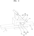
- the support parts 151A and 151B are fixedly coupled to the first body part 110 by using a fastening member such as a bolt in the disclosure.
- a fastening member such as a bolt
- the disclosure is not limited thereto, and the support parts 151A and 151B may be integrally formed with the first body part 110.
- the support parts 151A and 151B are provided at the center portion of the first body part 110, and the locking main body parts 153A and 153B that are described later are respectively coupled to both sides of the support parts 151A and 151B.
- the support parts 151A and 151B each may be provided as a plurality of support parts to correspond to the locking main body parts 153A and 153B that are plurally provided, or as a single member to be coupled to each of the locking main body parts 153A and 153B at both sides.
- the support parts 151A and 151B are coupled to the locking main body parts 153A and 153B arranged at the left and right sides with respect to the center portion of the first body part 110.
- the contact parts 153Aa and 153Ba are disposed between the first body part 110 and the second body part 130 to be capable of moving between the first body part 110 and the second body part 130.
- the contact parts 153Aa and 153Ba contact the elastic members 153Ab and 153Bb that are described later, and may be moved between the first body part 110 and the second body part 130 due to the elastic resilience of the elastic members 153Ab and 153Bb.
- the elastic members 153Ab and 153Bb may be provided at both sides of the support parts 151A and 151B disposed at the center portion of the first body part 110.
- the elastic members 153Ab and 153Bb respectively contact the contact parts 153Aa and 153Ba disposed at both sides with respect to the center portion of the first body part 110, or are integrally formed with the support parts 151A and 151B to respectively penetrate the support parts 151A and 151B and contact the contact parts 153Aa and 153Ba.
- an elastic member 153Ab may have elastic resilience in a direction from the right to the left.
- the elastic members 153Ab and 153Bb may be compression springs that resist compression.
- the unlocking units 160A and 160B may push the contact parts 153Aa and 153Ba outward from the center portion of the first body part 110.
- the unlocking units 160A and 160B may be coupled to the first body part 110 to be capable of rotating clockwise or counterclockwise.
- the unlocking units 160A and 160B may include unlocking main bodies 161A and 161B and an unlocking pin portion 165.
- Bent portions 163A and 163B may protrude toward the locking unit 150 respectively from one end portions of the unlocking units 160A and 160B, particularly the unlocking main bodies 161A and 161B, facing the locking unit 150, particularly the contact parts 153Aa and 153Ba.
- the bent parts 163A and 163B protrude, when the unlocking units 160A and 160B push the contact parts 153Aa and 153Ba, the bent parts 163A and 163B formed on the unlocking main bodies 161A and 161B and the contact parts 153Aa and 153Ba contact each other at one or more points. Accordingly, when the bent parts 163A and 163B push the contact parts 153Aa and 153Ba in a direction in which the interval between one surface of the first body part 110 and one surface of the second body part 130, which face each other, increases, movement stability of the contact parts 153Aa and 153Ba may be improved.
- the unlocking units 160A and 160B may respectively push the locking units 150A and 150B, particularly the contact parts 153Aa and 153Ba, disposed at both sides with respect to the center portion of the first body part 110.
- the unlocking units 160A and 160B separate the contact parts 153Aa and 153Ba, which are disposed at both sides with respect to the center portion of the first body part 110, from the first body part 110 and the second body part 130, the locking state of the locking apparatus 100 may be released.
- the second body part 230 is disposed on the movement path formed in the first body part 210 and moves in the horizontal direction (based on FIG. 6 ) along the movement axis X 1 .
- an interval between an upper inner surface of the first body part 210 and the upper surface of the second body part 230, which face each other, and an interval between a lower inner surface of the first body part 210 and the lower surface of the second body part 230, which face each other, may each decrease in one direction with respect to the center portion of the first body part 210.
- FIGS. 7 and 8 are side views of a locking apparatus according to another embodiment.
- FIGS. 9A and 9B are perspective views of a surgical instrument provided with the locking apparatus according to another embodiment.
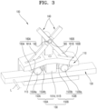
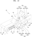
- a locking apparatus 300 may include a first body part 310, a second body part 330, a locking unit 350, an unlocking unit 360, a pushing plate part 370, a base part 380, a guide member 390, and a locking apparatus rotation axis part 395.
- the locking unit 350 denotes locking main body parts 353A and 353B. Referring to FIGS. 7 and 8 , in the locking apparatus 300 according to another embodiment, the locking unit 350 may include two locking units.
- three locking units 350A, 350B, and 350C that is, three locking main body parts 353A, 353B, and 353C, are disposed along a rotational direction of the second body part 330, or n-number of locking units, where n is an integer exceeding 3, may be formed as the locking units 350.
- the locking main body parts 353A, 353B, and 353C particularly contact parts 353Aa, 353Ba, and 353Ca, move in a direction in which an interval between the first body part 310 and the second body part 330 decreases, so as to be stuck by respectively contacting the respective surfaces of the first body part 310 and the second body part 330, which face each other. Accordingly, as a frictional force increases, the locking performance may be improved.
- a movement path, along which the second body part 330 is movable, may be formed in the first body part 310 according to another embodiment.
- the movement path may be formed outside the first body part 310, and the locking main body parts 353A and 353B is movable along one surface forming the outside of the first body part 310.
- the second body part 330 according to another embodiment has a hollow space therein, and the first body part 310 may be disposed inside the second body part 330.
- the second body part 330 is coaxially with the first body part 310, and may be disposed to be rotatable outside the first body part 310. In other words, the second body part 330 may be disposed to be rotatable around the same rotation axis with the first body part 310.
- the second body part 330 according to another embodiment has a cylindrical shape having a constant radius, a constant radius of curvature, and a hollow space therein.
- the second body part 330 may be connected to a movable portion, for example, the connection member L such as a wire, in a separate apparatus, such as the surgical instruments 1 and 2, where the locking apparatus 300 is installed.
- the connection member L such as a wire
- the first body part 310, the unlocking unit 360, and the locking main body parts 353A and 353B may be disposed inside the second body part 330 according to another embodiment. Accordingly, when the second body part 330 rotates outside the first body part 310, a certain apparatus connected to the second body part 330 is capable of rotational motion or linear motion with the second body part 330.
- an interval between one surface of the first body part 310 and one surface of the second body part 330, which face each other, may decrease in a clockwise or counterclockwise direction around the locking apparatus rotation axis part 395 that is the rotation center of the first body part 310, as a rotation center.
- the second body part 330 may be prevented from moving in any one direction relative to the first body part 310.
- the interval between one surface of the first body part 310 and one surface of the second body part 330 may decrease in a clockwise with respect to the center of the first body part 310.
- a locking state may be established, in which the clockwise (based on FIG. 7 ) movement of the second body part 330, that is, the movement of the second body part 330 relative to the first body part 310 in one direction (clockwise) may be prevented.
- the disclosure is not limited thereto, and a modification of an embodiment may be possible such that the interval between one surface of the first body part 310 and one surface of the second body part 330 decreases in the counterclockwise direction with respect to the center of the first body part 310.
- the locking main body parts 353A and 353B move in the counterclockwise direction to simultaneously contact the first body part 310 and the second body part 330 therebetween, the movement of the second body part 330 in the counterclockwise direction, that is, a locking state may be established, in which the second body part 330 is prevented from moving in one direction (counterclockwise direction) relative to the first body part 310.
- first body parts 410A, 410B, 510A, and 510B With respect to the centers of first body parts 410A, 410B, 510A, and 510B, relative movements of the second body parts 430A, 430B, 530A, and 530B and a certain member connected to each of the second body parts 430A, 430B, 530A, and 530B to the first body parts 410A, 410B, 510A, and 510B in the clockwise and counterclockwise directions may be prevented.
- the locking apparatuses 400A and 400B in which the interval between one surface of each of the first body parts 410A and 410B and one surface of each of the second body parts 430A and 430B decreases in the clockwise direction, are provided on the same pitch axis forming a surface symmetry with respect to a plane (based on a Y-Z plane of FIG. 9A ) that is perpendicular to the pitch axis.
- the locking apparatuses 500A and 500B in which an interval between one surface of each of the first body parts 510A and 510B and one surface of each of the second body parts 530A and 530B decrease in the clockwise direction, are provided on the same yaw axis forming a surface symmetry with respect to a plane (based on a X-Y plane of FIG. 9A ) that is perpendicular to the yaw axis.
- a relative movement of a portion (based on a bent part 35 of FIG. 9A ) that is simultaneously connected to each of the second body parts 430A and 430B to a portion (based on a pitch manipulation part 31 of FIG. 9A ) that is simultaneously connected to each of the first body parts 410A and 410B, in the clockwise and counterclockwise directions, may be prevented.
- a relative movement of a portion (based on FIG. 9A , the pitch manipulation part 31) that is simultaneously connected to each of the second body parts 530A and 530B to a portion (based on a yaw manipulation part 32 of FIG. 9A ) that is simultaneously connected to each of the first body parts 510A and 510B, in the clockwise and counterclockwise directions, may be prevented.
- the locking main body parts 353A and 353B are placed in a portion where the outer surface of the first body part 310 disposed inside the second body part 330 is formed as an inclined surface, and thus the locking main body parts 353A and 353B stably contact the first body part 310 and the second body part 330, thereby generating a frictional force.
- the locking main body parts 353A and 353B are disposed to be capable of moving between the first body part 310 and the second body part 330, particularly between the outer circumferential surface the first body part 310 and the inner circumferential surface of the second body part 330.
- the locking main body parts 353A and 353B are connected to the first body part 310 and moving between the first body part 310 and the second body part 330 and may include the contact parts 353Aa and 353Ba and elastic members 353Ab and 353Bb.
- the contact parts 353Aa and 353Ba are disposed between the first body part 310 and the second body part 330 and have a cylindrical shape like the contact parts 153Aa, 153Ba, 253Aa, 253Ba, 253Ca, and 253Da according to the embodiments.
- the disclosure is not limited thereto, and the contact parts 353Aa and 353Ba may have a ball shape.
- the elastic members 353Ab and 353Bb are disposed between the contact parts 353Aa and 353Ba and the first body part 310, have elastic resilience in a direction in which the interval between the first body part 310 and the second body part 330, which face each other, decreases, and may be formed as a spring having a coil shape like the elastic members 153Ab, 153Bb, 253Ab, 253Bb, 253Cb, and 253Db according to the embodiments.
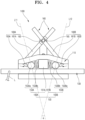
- the locking support part 317 may include a plurality of locking support parts forming a symmetry in the upper and lower sides (based on FIG. 8 ) with respect to a movement axis X 2 of the pushing plate part 370, particularly a pushing plate main body 371 that is described later.
- the second locking main body part 353B may be disposed in the lower side (based on FIG. 8 ) with respect to the movement axis X 2 of the pushing plate part 370, particularly connected to the locking support part 317 disposed in the lower side with respect to the movement axis X 2 of the pushing plate part 370.
- the second locking main body part 353B may include a contact part 353Ba and an elastic member 353Bb.
- the elastic member 353Bb connected to the contact part 353Ba has elastic resilience in the outward direction of the contact part 353Ba, that is, in a direction away from the locking support part 317, and due to the elastic resilience of the elastic member 353Bb, the contact part 353Ba may be pushed toward the inclined surface formed in the first body part 310.
- the unlocking unit 360 is connected to the first body part 310, disposed on the movement path of the locking main body parts 353A and 353B, and may push the locking main body parts 353A and 353B in a direction (based on the counterclockwise direction in FIGS. 7 and 8 ) in which the interval between the respective surfaces of the first body part 310 and the second body part 330, which face each other, increases.
- the unlocking unit 360 may include an unlocking main body and a bent part 363.
- a hole portion may be formed at the center of the unlocking main body, and a protruding portion (corresponding to a protruding portion 631 of FIG. 11 ) protruding toward the unlocking unit 360 may be formed in the second body part 330 to be inserted in the hole portion.
- a rotation path of the unlocking unit 360 may be provided, and the unlocking unit 360 may rotated clockwise or counterclockwise while maintaining the rotation center.
- the bent part 363 is provided in the unlocking main body and may be extend in the length direction of the rotation center axis of the unlocking main body from an end portion of the unlocking main body (361).
- the bent part 363 is disposed on the movement path of the locking main body parts 353A and 353B, particularly the contact parts 353Aa and 353Ba, and may push the contact parts 353Aa and 353Ba in a direction in which the interval between the respective surfaces of the first body part 310 and the second body part 330, which face each other, increases as the unlocking unit 360 is rotated.
- the contact part 353Aa disposed in the upper side with respect to the movement axis X 2 of the pushing plate part 370 and the contact part 353Ba disposed in the lower side with respect to the movement axis X 2 of the pushing plate part 370 may simultaneously pushed.
- the pushing plate part 370 is disposed to be capable of moving on the first body part 310 and may move in contact with or not in contact with the first body part 310.
- the structure of the base part 380 according to another embodiment is the same as that of a base part 680 according to another embodiment, a detailed description thereof is presented later.
- a head part (not referenced) formed in the guide member 390 may be formed greater than the width of the pushing plate guide part 372, and thus the pushing plate main body 371 may be prevented from escaping from the first body part 310, and as the pushing plate main body 371 is disposed between the first body part 310 and the head part, the pushing plate main body 371 may push the unlocking unit 360 that the pushing plate main body 371 faces.
- head part As the head part according to another embodiment is the same as a head part 691 according to another embodiment, a detailed description thereof is presented later.
- the contact parts 353Aa and 353Ba are stuck between the locking main body parts 353A and 353B, particularly one surface of the first body part 310 and one surface of the second body part 330, which face each other, and the rotation of the second body part 330 in the clockwise direction (based on FIG. 7 ) is prevented due to a frictional force generated due to the being stuck therebetween, but the rotation in the opposite direction that is the in the counterclockwise direction (based on FIG. 7 ) is not prevented.
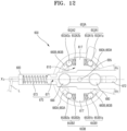
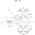
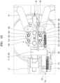
- the locking main body parts 653A1, 653A2, 653B1, and 653B2 are disposed to be movable between the first body part 610 and the second body part 630, particularly between an outer circumferential surface of the first body part 610 and an inner circumferential surface of the second body part 630.
- the locking main body parts 653A1, 653A2, 653B1, and 653B2 may include the first locking main body parts 653A1 and 653A2 and the second locking main body parts 653B1 and 653B2.
- the first locking main body parts 653A1 and 653A2 are coupled to one side of the first body part 610, particularly in the upper side (based on FIG. 12 ) with respect to the movement axis X 2 of the pushing plate part 670 that is described later.
- the second locking main body parts 653B1 and 653B2 may be formed at positions symmetric with respect to the positions of the first locking main body parts 653A1 and 653A2, and may be coupled to the other side (based on the lower side in FIG. 12 ) that is symmetric with respect to one side of the first body part 610 (based on the upper side in FIG. 12 ) to which the first locking main body parts 653A1 and 653A2 are coupled.
- the second locking main body parts 653B1 and 653B2 may be disposed in the lower side (based on FIG. 12 ) with respect to the movement axis X 2 of the pushing plate part 670, particularly with respect to the movement axis X 2 of the pushing plate part 670, and connected to the locking support part 617 disposed in the lower side of the first body part 610, and may include a plurality of second locking main body parts.
- the second locking main body parts 653B1 and 653B2 may be disposed to be symmetric with respect to the locking support part 617as a center portion.
- the second locking main body parts 653B1 and 653B2 may include the contact parts 653B1a and 653B2a and the elastic members 653B1b and 653B2b, and the elastic members 653B1b and 653B2b respectively connected to the contact parts 653B1a and 653B2a may have elastic resilience to push the contact parts 653B1a and 653B2a outward from the locking support part 617. Due to the elastic resilience of the elastic members 653B1b and 653B2b, the contact parts 653B1a and 653B2a may be pushed toward the inclined surface formed in the first body part 610.
- the locking main body parts 653A1, 653A2, 653B1, and 653B2 are coupled to both sides of the locking support part 617 formed in the first body part 610.
- a total of four locking main body parts 653A1, 653A2, 653B1, and 653B2 including the first locking main body parts 653A1 and 653A2 and the second locking main body parts 653B1 and 653B2.
- the disclosure is not limited thereto, and various modifications of the embodiments are possible such that over four locking main body parts may be disposed along the circumference of the first body part 610 commonly having the rotation center of the second body part 630.
- the unlocking units 660A and 660B may include the unlocking main bodies 661A and 661B and the bent parts 663A and 663B.
- the bent parts 663A and 663B are provided on the unlocking main bodies 661A and 661B and may extend from end portions of the unlocking main bodies 661A and 661B in a rotation center axis direction of the unlocking main bodies 661A and 661B.
- the bent parts 663A and 663B are disposed on the locking unit 650, particularly on a movement path of the contact parts 653A1a, 653A2a, 653B1a, and 653B2a, and as the unlocking units 660A and 660B rotate, may push the contact parts 653A1a, 653A2a, 653B1a, and 653B2a in a direction in which the interval between the respective surfaces of the first body part 610 and the second body part 630, which face each other, increases.
- the unlocking units 660A and 660B may include a plurality of unlocking units, and the unlocking units 660A and 660B may receive power, particularly rotational power, from the pushing plate part 670 that is described later.
- the unlocking units 660A and 660B may rotate in different directions.
- the unlocking units 660A and 660B may be disposed to be origin symmetric with respect to the rotation center of the second body part 630.
- the locking main body part 653A1, particularly the contact part 653A1a, disposed in the upper right side (based on FIG. 12 ) with respect to the center of the first body part 610, and the locking main body part 653B1, particularly the contact part 653B1a, disposed in the lower left side (based on FIG. 12 ) with respect to the center of the first body part 610, may be simultaneously pushed.
- the locking main body parts 653A1 and 653B1 are pushed toward the center portion of the first body part 610, and thus the locking main body parts 653A1 and 653B1, particularly the contact parts 653A1a and 653B1a, are moved in a direction in which the interval between the first body part 610 and the second body part 630, which face each other, increases. Accordingly, locking may be released so that the rotation of the second body part 630 in the clockwise direction (based on FIG. 12 ) is possible.
- the locking main body part 653A2 particularly the contact part 653A2a, disposed in the upper left side (based on FIG. 12 ) with respect to the center of the first body part 610, and the locking main body part 653B2 disposed in the lower right side (based on FIG. 12 ) with respect to the center of the first body part 610, may be simultaneously pushed.
- the locking main body parts 653A2 and 653B2 are pushed toward the center portion of the first body part 610, the locking main body parts 653A2 and 653B2, particularly the contact parts 653A2a and 653B2a, are moved in a direction in which the interval between the first body part 610 and the second body part 630, which face each other, increases. Accordingly, the locking may be released so that the rotation in the in the counterclockwise direction (based on FIG. 12 ) of the second body part 630 to the first body part 610 is possible.
- the unlocking units 660A and 660B may include a plurality of unlocking units, and the unlocking units 660A and 660B may be respectively disposed to be origin symmetric with respect to the center of the second body part 630, that is, the center of the locking apparatus rotation axis part 695.
- bent parts 663A and 663B provided in the unlocking units 660A and 660B disposed on the movement path of the contact parts 653A1a, 653A2a, 653B1a, and 653B2a may be disposed to be original symmetric with respect to the center of the second body part 630, that is, the locking apparatus rotation axis part 695.
- the unlocking units 660A and 660B that are plural, not singular, rotate in different directions of the clockwise and counterclockwise directions
- the unlocking units 660A and 660B push the contact parts 653A1a, 653A2a, 653B1a, and 653B2a to move the contact parts 653A1a, 653A2a, 653B1a, and 653B2a in a direction in which the interval between one surface of the first body part 610 and one surface of the second body part 630, which face each other, increases.
- the locking main body parts 653A1 and 653A2 are disposed in the upper side at both sides of the center portion of the first body part 610 with respect to the movement axis X 2 of the pushing plate part 670, and the locking main body parts 653B1 and 653B2 may be disposed in the lower side at both sides of the first body part 610 corresponding thereto.
- the contact parts 653A1a, 653A2a, 653B1a, and 653B2a are moved due to the elastic resilience of the elastic members 653A1b, 653A2b, 653B1b, and 653B2b in a direction away from the center portion of the first body part 610, that is, in a direction in which the interval between one surface of the first body part 610 and one surface of the second body part 630, which face each other, decreases.
- the contact part 653A1a disposed in the upper right side (based on FIG. 12 ) with respect to the movement axis X 2 of the pushing plate part 670, and the contact part 653B1a disposed in the lower left side (based on FIG. 12 ) with respect to the movement axis X 2 of the pushing plate part 670, are stuck between the first body part 610 and the second body part 630, and a locking state may be established in which the movement of the first body part 610 to the second body part 630 in the clockwise direction (based on FIG. 12 ) is prevented due to the frictional force.
- the contact part 653A2a disposed in the upper left side (based on FIG. 12 ) with respect to the movement axis X 2 of the pushing plate part 670, and the contact part 653B2a disposed in the lower right side (based on FIG. 12 ) with respect to the movement axis X 2 of the pushing plate part 670, are struck between the first body part 610 and the second body part 630, and a locking state may be established in which the movement of the first body part 610 to the second body part 630 in the in the counterclockwise direction (based on FIG. 12 ) is prevented due to the frictional force.
- the locking main body parts 653A1, 653A2, 653B1, and 653B2 comprise a plurality of locking main body parts and are disposed at both sides with respect to the center portion of the first body part 610, and thus the movement of the first body part 610 to the second body part 630 in both directions may be prevented.
- the pushing plate part 670 that is singular and described later pushes the unlocking units 660A and 660B
- the unlocking units 660A and 660B push the locking main body parts 653A1, 653A2, 653B1, and 653B2 to move toward the center portion of the first body part 610, and thus the movement of the first body part 610 to the second body part 630 in both directions may be possible.
- the pushing plate part 670 is disposed to be movable on the first body part 610 and may transmit power to the unlocking units 660A and 660B.
- the pushing plate part 670 pushes the unlocking units 660A and 660B to transmit rotational power to the unlocking units 660A and 660B.
- the unlocking units 660A and 660B rotates counterclockwise or clockwise.
- the unlocking units 660A and 660B push the locking main body parts 653A1, 653A2, 653B1, and 653B2, particularly the contact parts 653A1a, 653A2a, 653B1a, and 653B2a
- the contact parts 653A1a, 653A2a, 653B1a, and 653B2a may be moved in a direction in which the interval between one surface of the first body part 610 and one surface of the second body part 630, which face each other, increases. Accordingly, the movement of the second body part 630 to the first body part 610 may be possible.
- the pushing plate part 670 may include the pushing plate main body 671 and a pushing plate elastic part 673.
- the pushing plate main body 671 moves on the first body part 610 may move in contact with or not in contact with the first body part 610.
- a pushing plate guide part 672 is formed in the pushing plate main body 671 in a movement direction of the pushing plate main body 671 (based on the X 2 axial direction in FIG. 12 ).
- the pushing plate guide part 672 has a hole portion shape through which the pushing plate main body 671 that is described later passes, and the guide member 690 may be coupled to the first body part 610 by passing through the pushing plate guide part 672 formed in the pushing plate main body 671.
- the guide member 690 may include a plurality of guide members and may be separately disposed on the first body part 610 with a certain interval in the movement direction of the pushing plate main body 671. Accordingly, the pushing plate main body 671 may be provided with a movement path and may stably move in a set path (based on the X 2 axial direction in FIG. 12 ).
- the pushing plate elastic part 673 is disposed between the base part 680 that is described later and the pushing plate main body 671 and has elastic resilience.
- the pushing plate elastic part 673 may be formed as a spring having a coil shape.
- the pushing plate elastic part 673 is disposed between a second base 683 that is described later and the pushing plate main body 671, and may push the pushing plate elastic part 673 when the pushing plate main body 671 moves by passing through the second base 683.
- the pushing plate elastic part 673 is compressed by the pushing plate main body 671 and may have elastic resilience in a direction in which the pushing plate elastic part 673 is away from the second base 683.
- the pushing plate elastic part 673 may push the pushing plate part 670 so that the locking apparatus 600 enters a locking state.
- the pushing plate elastic part 673 has elastic resilience in a direction in which the pushing plate main body 671 is away from the second base 683 (based on the direction from the right to the left in FIG. 12 ), but various modifications of the embodiments are possible such that, considering design factors, for example, the installation position of the second base 683 in equipment such as the surgical instrument 1 where the locking apparatus 600 is installed, the pushing plate elastic part 673 may have elastic resilience in a direction toward the second base 683 (based on the direction from the right to the left in FIG. 12 ).
- one surface facing the unlocking units 660A and 660B may be formed as the inclined surface S1 having the certain angle ⁇ 2 with respect to the movement axis X 2 of the pushing plate main body 671.
- the pushing plate main body 671 may be formed to be symmetric with respect to the movement axis X 2 .
- the pushing plate main body 671 pushes the unlocking unit 660A, particularly the bent part 663A, disposed in the upper right side (based on FIG. 12 ) of the first body part 610 and may simultaneously push the unlocking unit 660B, particularly the bent part 663B, disposed in the lower right side of the first body part 610 (based on FIG. 12 ).
- the pushing plate main body 671 is formed to be symmetric with respect to the movement axis X 2 , like one surface facing the unlocking unit 660A in the upper side (based on FIG. 12 ) forms the certain angle ⁇ 2 with respect to the movement axis X 2 , one surface facing the unlocking unit 660B in the lower side (based on FIG. 12 ) may form an angle ⁇ 2 having the same amount with respect to the movement axis X 2 .
- the unlocking unit 660A may have two bent parts 663A at the opposite ends thereof, and accordingly, the unlocking unit 660A that is singular and rotates may simultaneously push the two contact parts 653A1a and 653B1a.
- the unlocking unit 660B may also have two bent part 663B at the opposite ends thereof, and accordingly, the unlocking unit 660B that is singular and rotates may simultaneously push the two contact parts 653A2a and 653B2a.
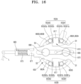
- the second inclined surface S2 is formed in front of the first inclined surface S1 when a direction in which the first inclined surface S1 pushes the unlocking units 660A and 660B (based on the direction from the right to the left in FIG. 16 ) is assumed to be the front side, and may be formed to be inclined in the same direction as the first inclined surface S1.
- the first inclined surface S1 pushes the unlocking unit 660A, particularly the bent part 663A in the upper right side with respect to the center of the first body part 610, the locking main body part 653A1 disposed in the upper right side and the locking main body part 653B1 disposed in the lower left side rotate counterclockwise.
- the second inclined surface S2 pushes the unlocking unit 660A, particularly the bent part 663A in the lower left side with respect to the center of the first body part 610, so as to provide additional power to rotate the unlocking unit 660A counterclockwise.
- the locking main body part 653B2 disposed in the lower right side and the locking main body part 653A2 disposed in the upper left side rotate clockwise.
- the second inclined surface S2 pushes the unlocking unit 660B, particularly the bent part 663B, in the upper left side with respect to the center of the first body part 610, so as to provide additional power to rotate the unlocking unit 660B clockwise.
- the bent part 663B disposed in the upper side with respect to the movement axis X 2 of the pushing plate main body 671 contacts the second inclined surface S2 and is pushed and rotated clockwise.
- the bent part 663A disposed in the lower side with respect to the movement axis X 2 of the pushing plate main body 671 contacts the second inclined surface S2 and is pushed and rotated counterclockwise.
- the pushing plate main body 671 is moved from the right to the left by the connection member L such as a wire connected thereto. Accordingly, the locking main body part 653A1 disposed in the upper right side and the locking main body part 653B1 disposed in the lower left side with respect to the center of the first body part 610 may rotate counterclockwise . Simultaneously, the locking main body part 653A2 disposed in the upper left side and the locking main body part 653B2 disposed in the lower right side with respect to the center of the first body part 610 may be simultaneously rotated.
- the base part 680 particularly the second base 683 and the pushing plate main body 671, are connected by the pushing plate elastic part 673.
- the pushing plate elastic part 673 has elastic resilience in a direction in which the pushing plate main body 671 is away from the second base 683.
- the pushing plate main body 671 is moved to the right (based on FIG. 13 ), due to the elastic resilience of the elastic members 653A1b, 653A2b, 653B1b, and 653B2b connected to the contact parts 653A1a, 653A2a, 653B1a, and 653B2a, the contact parts 653A1a, 653A2a, 653B1a, and 653B2a are pushed.
- the contact parts 653A1a, 653A2a, 653B1a, and 653B2a are moved in a direction in which the interval between one surface of the first body part 610 and one surface of the second body part 630, which face each other, decreases.
- the locking main body part 653A1 disposed in the upper right side the locking main body part 653B1 disposed in the lower left side with respect to the center of the first body part 610 may prevent the movement of the first body part 610 to the second body part 630 in the clockwise direction.
- the frictional force generated as the locking main body parts 653A1, 653A2, 653B1, and 653B2 are stuck between the first body part 610 and the second body part 630, which face each other may prevent the movement of the first body part 610 to the second body part 630 in both clockwise and counterclockwise directions.
- the base part 680 may include a first base 681 and the second base 683.
- the first base 681 is disposed outside the second body part 630.
- the second base 683 is fixed to the first base 681 and the first body part 610, and a hole portion (set with no reference numeral) may be formed in the second base 683 so that the pushing plate main body 671 passes therethrough.
- the second base 683 may be placed on a first body groove part 611 formed in the first body part 610. Accordingly, the first body part 610 may be prevented from rotating, and the rotation of the first body part 610 together due to the rotation of the unlocking units 660A and 660B may be prevented.
- the first base 681 may prevent escape of the second body part 630 in the rotation axis direction, and in this state, the first base 681 may be provided not to interfere with the rotation of the second body part 630.
- the first base 681 may not be provided as necessary.
- the base part 680 is fixed to a portion, for example, the surgical instrument 2, where the locking apparatus 600 is installed.
- the elastic resilience may be reinforced.
- the guide member 690 may be coupled to the first body part 610 and may penetrate the pushing plate guide part 672 that extends and is formed in the pushing plate part 670, particularly the pushing plate main body 671.
- the head part 691 formed in the guide member 690 is greater than the width of the pushing plate guide part 672, and may prevent the pushing plate main body 671 from escaping from the first body part 610.
- the pushing plate main body 671 is disposed between the first body part 610 and the head part 691, and the pushing plate main body 671 may push the unlocking units 660A and 660B, which face each other.
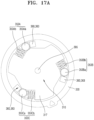
- the locking apparatus 695 according to another embodiment rotation axis part is connected to the first body part 610 and the second body part 630, and penetrates the unlocking units 660A and 660B, the first body part 610, and the second body part 630.
- the center axes that are the rotation centers of the first body part 610, the second body part 630, the unlocking units 660A and 660B may be matched with one another by the locking apparatus rotation axis part 695, and thus the unlocking units 660A and 660B that are formed to be the origin symmetric with respect to the center may push the locking main body parts 653A1, 653A2, 653B1, and 653B2 simultaneously which face each other, the control of the movement of the first body part 610 to the second body part 630 in both directions(that is, in the clockwise or counterclockwise direction), and the locking performance, may be improved.
- the locking apparatus rotation axis part 695 may prevent the change of the interval between the first body part 610 and the second body part 630 that is preset in the circumferential direction.
- the stuck-type locking apparatus may be switched to a locking state at any positions of the first body part and the second body part that move relative to each other.
- the second body part may move to the first body part within a certain range, and thus the locking apparatus is capable of switching regardless of the position of the second body part to the first body part.
- the locking apparatus when the locking apparatus is switched to the locking state, the locking apparatus enters the locking state regardless of the movement clearance of the first body part and the second body part.
- the unlocking unit for pushing the locking unit in a direction in which the interval between the first body part and the second body part increases is provided in the form of rotating coaxially with the rotation axes of the first body part and the second body part.
- a method of pushing a locking unit may be modified in various ways, which includes various modified methods of pushing a locking unit under the concept of pushing a locking unit for the release of a locking state.
- the pushing plate part capable of linear motion for the rotation of the unlocking unit capable of rotating is provided, the method of moving an unlocking unit that pushes a locking unit for the release of a locking state may be modified in various ways.
- the concept of the disclosure is not limited thereto, which includes various modified methods of moving the unlocking unit under the concept of moving the unlocking unit that pushes the locking unit for the release of a locking state.
- surgical instrument provided with the locking apparatus according to another embodiment (hereinafter, referred to as the "surgical instrument") is described below with reference to the accompanying drawings.
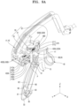
- FIGS. 9A and 9B are perspective views of a surgical instrument provided with the locking apparatus according to another embodiment.
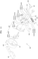
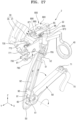
- the surgical instrument 1 provided with the locking apparatus according to another embodiment may include an end tool, a connection part, a manipulation part 30, the locking apparatuses 400A, 400B, 500A, and 500B, and a control part.
- end tool 10 is the same element as the end tool 10 of the surgical instrument 2 where a locking apparatus according to another embodiment that is described later is installed, a detailed description thereof is presented later.
- the surgical instruments 1 and 2 where the locking apparatuses according to other embodiments of the disclosure are respectively installed may be manually moved for laparoscopic surgery or various other surgeries.
- a surgeon may perform surgery on a surgical site by manually operating the surgical instruments 1 and 2 by hands.
- the gripping of the end tool 10 is possible by the actuation operation of the finger ring part 40, and the rotation operation of the end tool 10 is possible by the rotation of the handle part 50 or the finger ring part 40.
- the actuation operation denotes that, while rotating around an axis parallel to a yaw motion rotation axis or other axis, as a center, each of a plurality of finger ring parts provided as the finger ring part 40 rotates in opposite directions to be closed or opened.
- the manipulation part 30 may include the pitch manipulation part 31, the yaw manipulation part 32, and the bent part 35.
- the power transmission wires 41 and 42 are provided in one pair, the disclosure is not limited thereto, and various modifications of the embodiments are possible such that the power transmission wires 41 and 42 may be provided in one body or may include three or more power transmission wires according to the operation design of the end tool 10 of the surgical instrument 1.
- the manipulation part 30, particularly a relative movement among the pitch manipulation part 31, the yaw manipulation part 32, and the bent part 35 allows the power transmission wires 41 and 42 to move, and consequently the pitch or yaw motion of the end tool 10 occurs.
- the rotational motion of the pitch manipulation part 31 and the yaw manipulation part 32 causes the rotational motion of the end tool 10, and when the rotational motion of the pitch manipulation part 31 and the yaw manipulation part 32 is restricted by the locking apparatuses 400A, 400B, 500A, and 500B, the rotational motion of the end tool 10 is restricted as well.
- each of the pitch manipulation part 31 and the yaw manipulation part 32 is capable of rotational motion in a clockwise or counterclockwise direction, and may include two locking apparatuses for restricting a rotational motion in both directions.
- the two locking apparatuses 400A and 400B may be provided to restrict a rotational motion of the pitch manipulation part 31 in both directions
- the two locking apparatuses 500A and 500B may be provided to restrict a rotational motion of the yaw manipulation part 32 in both directions.
- a user controls the locking apparatuses 400A, 400B, 500A, and 500B through the control part to control a relative movement among the pitch manipulation part 31, the yaw manipulation part 32, and the bent part 35.
- the control part may include the finger ring part 40, the handle part 50, a first lever part 60, a second lever part 70, a hook part 71, wire parts 81 and 85, wire tube parts 82 and 86, and a wire holder part 61.
- control part controls the relative movement among the pitch manipulation part 31, the yaw manipulation part 32, and the bent part 35 through the movements of the wire parts 81 and 85
- the disclosure is not limited thereto, and various modifications of the embodiments are possible such that the relative movement may be controlled in a slide method or a button method.
- the wire part denotes a first wire 81 and a second wire 85
- the wire tube part denotes a first wire tube 82 and a second wire tube 86.
- the surgical instrument 1 may include a plurality of locking apparatuses, particularly the first locking apparatus 400A, the second locking apparatus 400B, the third locking apparatus 500A, and the fourth locking apparatus 500B.
- a pitch motion of the manipulation part 30 of the surgical instrument 1 is performed by the relative movement between the pitch manipulation part 31 and the bent part 35, and the relative movement refers to a rotational motion in both clockwise and counterclockwise directions.
- a yaw motion of the manipulation part 30 of the surgical instrument 1 is performed by a relative movement between the pitch manipulation part 31 and the yaw manipulation part 32, and the relative movement refers to a rotational motion in both clockwise and counterclockwise directions.
- each of the first locking apparatus 400A and the second locking apparatus 400B are the same as those of the locking apparatus 300 according to another embodiment, detailed descriptions of redundant elements thereof are omitted.
- the first locking apparatus 400A may be formed such that the interval between the first body part 410A and the second body part 430A, which face each other, decrease clockwise with respect to the center of the first body part 410A.
- the first body part 410A is coupled to the pitch manipulation part 31 and capable of rotating around the pitch axis as a center axis, and the second body part 430A is coupled to the bent part 35.
- the interval between the first body part 410A and the second body part 430A decreases clockwise (viewed in a negative X-axis direction with respect to the pitch axis in FIG. 9A ), and Accordingly, the rotation of the first body part 410A to the second body part 430A in the in the counterclockwise direction (viewed in the negative X-axis direction with respect to the pitch axis in FIG. 9A ) may be prevented.
- the pitch manipulation part 31 may be prevented from rotating in the in the counterclockwise direction (viewed in the negative X-axis direction with respect to the pitch axis in FIG. 9A ) with respect to the bent part 35.
- the "negative X-axis direction” denotes a direction from the right to the left with respect to a Y-Z plane in FIG. 9A .
- the second locking apparatus 400B may be formed to prevent the pitch manipulation part 31 from rotating in the clockwise direction (viewed in the negative X-axis direction with respect to the pitch axis in FIG. 9A ) with respect to the bent part 35.
- the second locking apparatus 400B When the second locking apparatus 400B is coupled to the manipulation part 30 by being reversed in the opposite direction to the first locking apparatus 400A with respect to the pitch axis, the second locking apparatus 400B may prevent the pitch manipulation part 31 from rotating in a direction opposite to the rotational direction that is prevented by the first locking apparatus 400A.
- the second locking apparatus 400B may be located in a direction opposite to the first locking apparatus 400A, the first body part 410B is coupled to the pitch manipulation part 31 to rotate around the pitch axis as a center axis, and the second body part 430B is coupled to the bent part 35.
- the interval between the first body part 410B and the second body part 430B of the second locking apparatus 400B decreases in the clockwise direction (based on the positive X-axis direction in FIG. 9B ). Accordingly, the rotation of the first body part 410B to the second body part 430B in the in the counterclockwise direction (based on the positive X-axis direction in FIG. 9B ) may be prevented.
- the negative X-axis direction denotes a direction from the right to the left with respect to the Y-Z plane in FIG. 9A .
- a pitch motion particularly a rotational motion of the pitch manipulation part 31 and the yaw manipulation part 32, the finger ring part 40, and the handle part 50 connected thereto relative to the bent part 35 around the pitch axis as a center axis may be prevented.
- the second body parts 430A and 430B are capable of relative movement with respect to the first body parts 410A and 410B, the rotational motion of the pitch manipulation part 31 and the yaw manipulation part 32, the finger ring part 40, and the handle part 50 connected thereto to the bent part 35 around the pitch axis as a center axis is possible, and thus the pitch motion of the end tool 10 is possible.
- each of the third locking apparatus 500A and the fourth locking apparatus 500B are the same as those of the locking apparatus 300 according to another embodiment, detailed descriptions of redundant elements thereof are omitted.
- the third locking apparatus 500A may be formed such that the interval between the first body part 510A and the second body part 530A, which face each other, decreases in the clockwise direction with respect to the center of the first body part 510A.
- the first body part 510A is coupled to the yaw manipulation part 32 and may be capable of rotating around the yaw axis as a center, and the second body part 530A is coupled to the pitch manipulation part 31.
- the interval between the first body part 510A and the second body part 530A decreases in the clockwise (viewed in the negative Z-axis direction with respect to the yaw axis in FIG. 9A ). Accordingly, the rotation of the first body part 510A to the second body part 530A in the counterclockwise direction (viewed in the negative Z-axis direction with respect to the yaw axis in FIG. 9A ) may be prevented.
- the "negative Z-axis direction” denotes a direction from the top to the bottom with respect to the X-Y plane in FIGS. 9A and 9B .
- the fourth locking apparatus 500B may be formed to prevent the rotation of the yaw manipulation part 32 to the pitch manipulation part 31 in the clockwise (in the negative Z-axis direction with respect to the yaw axis in FIG. 9A ).
- the fourth locking apparatus 500B is coupled to the manipulation part 30 by being reversed in the opposite direction to the third locking apparatus 500A with respect to the yaw axis, the prevention in the opposite direction to the rotational direction prevented by the third locking apparatus 500A is possible.
- the fourth locking apparatus 500B when the fourth locking apparatus 500B is viewed in the positive Z-axis direction (in the direction from the bottom to the top with respect to the X-Y plane in FIG. 9A ), that is, from the bottom to the top (based on FIG. 9A ), the interval between the first body part 510B and the second body part 530B of the fourth locking apparatus 500B decreases in the clockwise direction (based on the positive Z-axis direction in FIG. 9A ). Accordingly, the rotation of the first body part 510A to the second body part 530B in the counterclockwise direction (based on the positive Z-axis direction in FIG. 9A ) may be prevented.
- the negative Z-axis direction in FIG. 9A denotes the direction from the top to the bottom with respect to the X-Y plane in FIG. 9A .
- the rotation of the yaw manipulation part 32 to the pitch manipulation part 31 in both clockwise and counterclockwise directions may be simultaneously prevented. Accordingly, a yaw motion, particularly a rotational motion of the yaw manipulation part 32 and the finger ring part 40 and the handle part 50 connected thereto relative to the pitch manipulation part 31 around the yaw axis as a center axis may be prevented.
- each of the first body parts 510A and 510B of the third locking apparatus 500A and the fourth locking apparatus 500B is coupled to the pitch manipulation part 31, and each of the second body parts 530A and 530B is coupled to the yaw manipulation part 32.
- the rotational motion of the yaw manipulation part 32 and the finger ring part 40 and the handle part 50 connected thereto with respect to the pitch manipulation part 31 around the yaw axis as a center axis is possible, and thus the yaw motion of the end tool 10 is possible.
- a fifth locking apparatus 700 that is singular and prevents a relative movement in both directions controls a pitch motion
- a sixth locking apparatus 800 that is singular and prevents a relative movement in both directions controls a yaw motion.
- the connection part 20 the manipulation part 30, the finger ring part 40, the power transmission wires 41 and 42, the handle part 50, the first lever part 60, the second lever part 70, the hook part 71, the first wire 81, the first wire tube 82, the second wire 85, the second wire tube 86, and the wire holder part 61
- the handle part 50 the first lever part 60, the second lever part 70, the hook part 71, the first wire 81, the first wire tube 82, the second wire 85, the second wire tube 86, and the wire holder part 61
- related descriptions are presented in detail in the surgical instrument 2 provided with the locking apparatus according to another embodiment that is described later.
- the locking apparatuses 400A, 400B, 500A, and 500B described in the specification are capable of at least one operation of pitch, yaw, and actuation operations of the above-described surgical instrument, not applied only to an apparatus capable of joint movement.
- the locking apparatuses 400A, 400B, 500A, and 500B according to the embodiments are installed, not only the locking apparatuses 400A, 400B, 500A, and 500B according to the embodiments, but also the locking apparatus 100 according to the embodiment and the locking apparatus 200 according to another embodiment, which are locked or unlocked through a linear motion, may be employed.
- two one-way locking apparatuses are provided for the restriction of each motion in both directions.
- the one-way locking apparatuses for restricting the rotational motion in the same direction are provided by being reversed (in the opposite reference rotation axis directions of the rotational motion), so as to restrict the rotational motion of a pitch or yaw motion in both directions, but other modified configurations may be possible.
- one-way locking apparatuses that restrict a rotational motion in the opposite directions are configured to have a rotation axis in the same direction, so as to be configured to restrict the rotational motion of a pitch or yaw motion in both directions.
- the configuration described in the present embodiment does not limit the concept of the disclosure, is to explain the concept that one-way locking apparatus is provided in twos to restrict a rotational motion of a certain motion (a pitch or yaw motion) in both directions, and is to be understood as including various modified examples under such a concept.
- surgical instrument provided with the locking apparatus according to another embodiment (hereinafter, referred to as the "surgical instrument") is described below with reference to the accompanying drawings.
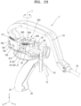
- the surgical instrument 2 provided with the locking apparatus may include the end tool 10, the connection part 20, the manipulation part 30, the locking apparatuses 700 and 800, and the control part.
- a user controls the locking apparatuses 700 and 800 through the control part, thereby controlling a relative movement among the pitch manipulation part 31, the yaw manipulation part 32, and the bent part 35.
- the control part may include the finger ring part 40, the handle part 50, the first lever part 60, the second lever part 70, the hook part 71, the wire parts 81 and 85, the wire tube parts 82 and 86, and the wire holder part 61.
- the locking apparatuses 700 and 800 include a plurality of locking apparatuses, and the locking apparatuses 700 and 800 may control a pitch motion and a yaw motion, respectively.
- the end tool 10 may include a jaw that is described later and provided at one end of the connection part 20, and may perform rotating, gripping, and cutting through a certain structure.
- the jaw is formed to be capable of rotating in two or more directions.
- the end tool 10 is engaged with the manipulation part 30 that is described later, and when the movement of the manipulation part 30 is prevented by the locking apparatuses 700 and 800, the movement of the end tool 10 may be prevented as well.
- the pitch motion denotes rotating around the pitch axis as a rotation center
- the yaw motion denotes rotating around the yaw axis as a rotation center
- the pitch axis for a pitch motion may denote a first rotation axis in a claim
- the yaw axis for a yaw motion may denote a second rotation axis in a claim.
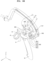
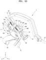
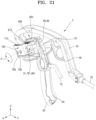
- a user may perform a pitch motion and a yaw motion while holding the handle part 50 using a hand, particularly, referring to FIG. 18 , perform a pitch motion around the pitch axis as a rotation center and a yaw motion around the yaw axis as a rotation center while holding the handle part 50.
- the yaw manipulation part 32 is capable of relative movement with respect to the pitch manipulation part 31 around the yaw axis as a center axis.
- the yaw manipulation part 32 may be connected to the finger ring part 40 and the handle part 50 so as to be engagingly moved (or rotated) as a user manipulates the finger ring part 40 and the handle part 50.
- the pitch manipulation part 31 may perform a relative movement with respect to the bent part 35 around the pitch axis as a rotation center.
- the pitch manipulation part 31 is connected to the yaw manipulation part 32, the finger ring part 40, and the handle part 50, and when a user performs a pitch motion rotating around the pitch axis as a rotation center by holding the handle part 50 or inserting a finger into the finger ring part 40, the pitch manipulation part 31 and the yaw manipulation part 32, the handle part 50, and the finger ring part 40 altogether pitch-rotate around the pitch axis as a rotation center.
- the configuration of the locking apparatuses 700 and 800 of the surgical instrument 2 provided with the locking apparatus according to another embodiment is the same as that of the locking apparatus 600 according to another embodiment, except that the locking apparatus 700 for controlling a pitch motion rotates around the pitch axis as a rotation center and the locking apparatus 800 for controlling a yaw motion rotates around the yaw axis as a rotation center, detailed descriptions of any redundant portions are omitted.
- a locking apparatus for controlling a pitch motion and a locking apparatus for controlling a yaw motion are defined to be the fifth locking apparatus and the sixth locking apparatus, respectively.
- the second body part 730 may be coupled to the bent part 35, and as the first body part 710 moves relative to the second body part 730, the pitch manipulation part 31 may rotate relative to the bent part 35.
- the pitch manipulation part 31 and the bent part 35 may rotate relative to each other.
- the yaw manipulation part 32 and the handle part 50 that are connected to the finger ring part 40 with respect to the pitch manipulation part 31 may rotate around the yaw axis as a rotation center.
- the finger ring part 40 and the handle part 50 that are connected to the yaw manipulation part 32 may rotate relative to the pitch manipulation part 31.
- a pushing plate main body 871 of a pushing plate part 870 of the sixth locking apparatus 800 is coupled to the second wire 85, and as the second wire 85 is moved due to the rotation of the first lever part 60 that is described later and by a pushing plate elastic part 873, the pushing plate part 870 may be moved in a "locking direction".
- the pushing plate elastic part 873 may be a tension spring resisting tension and may facilitate a movement of the pushing plate part 870 in any one direction.
- a locking unit 850 is stuck between the first body part 810 and the second body part 830 capable of moving relative to each other, and thus, a locking state in which a relative movement between the first body part 810 and the second body part 830 is prevented may be established by a frictional force generated at this time.
- FIG. 18 illustrates a locking state, in which, as the first lever part 60 rotates with respect to the handle part 50, the pushing plate main body 871 is moved in the "locking direction", and as the locking unit 850, particularly the locking main body part 853, is stuck between the first body part 810 and the second body part 830, a frictional force is generated, and accordingly a locking state may be established, in which a relative movement between the first body part 810 and the second body part 830, particularly a yaw motion that is a relative movement between the pitch manipulation part 31 and the yaw manipulation part 32, is prevented.
- the handle part 50 and the yaw manipulation part 32 altogether may yaw-rotate around the yaw axis as a rotation center
- the handle part 50, the yaw manipulation part 32, and the pitch manipulation part 31 altogether may pitch-rotate around the pitch axis as a rotation center.
- the finger ring part 40 may rotate around the rotation axis thereof as a center to perform the actuation operation of the end tool 10, but the rotation of the handle part 50 and the yaw manipulation part 32 altogether around the yaw axis as a rotation center is prevented.
- a yaw motion particularly an operation that the yaw manipulation part 32 and the finger ring part 40 altogether rotate around the yaw axis as a rotation center with respect to the pitch manipulation part 31, may be performed.
- the handle part 50 has a hollow inside and may provide a movement path of the first wire 81, the first wire tube 82, the second wire 85, and the second wire tube 86 that are described later.
- the handle part 50 is connected to the first lever part 60, and the first lever part 60 may rotate around a rotation axis L1 of the first lever part 60 (based on FIG. 27 ) as a rotation center at a certain portion of the handle part 50.
- a tube holder part 90 that is described later is installed inside the handle part 50 to fix the position of certain portions of the first wire tube 82 and the second wire tube 86, and the first wire 81 and the second wire 85 are located inside the first wire tube 82 and the second wire tube 86, respectively.
- the tube holder part 90 may be not only formed inside the handle part 50, but also coupled to second bases 783 and 883 or integrally formed with the second bases 783 and 883.
- the first lever part 60 of the surgical instrument 2 provided with the locking apparatus is installed between the handle part 50 and the second lever part 70 that is described later.
- one side of the first lever part 60 may be rotatably coupled to the handle part 50
- the second lever part 70 may be rotatably coupled to the other side thereof opposite to the one side.
- the locking units 750 and 850 are moved in a direction in which the interval between the first body parts 710 and 810 and the second body parts 730 and 830 decreases. Due to a frictional force generated as the locking units 750 and 850 are respectively stuck between the first body parts 710 and 810 and the second body parts 730 and 830, a locking state is established, in which a relative movement between the first body parts 710 and 810 and the second body parts 730 and 830 is prevented.
- the user may control a pitch motion around the pitch axis as a rotation center and a yaw motion around the yaw axis as a rotation center.
- the second lever part 70 is detachably coupled to the handle part 50 in a hook method, and the hook part 71 may be formed in one end portion of the second lever part 70.
- a catch recess part 51 is formed in the handle part 50 to have the hook part 71 accommodated therein, and a catch step part 52 may protrude from an end portion of the catch recess part 51 to catch the hook part 71.
- the lever spring 65 of the surgical instrument 2 provided with the locking apparatus may have a coil shape and elastic resilience to rotate around the rotation axis L1 of the first lever part 60 as a center axis in the clockwise or counterclockwise direction.
- the lever spring 65 may be installed at a portion where the handle part 50 and the first lever part 60 are connected to each other, and as the lever spring 65 has elastic resilience to rotate around the rotation axis L1 of the first lever part 60 in the clockwise direction (based on FIG. 27 ), and thus the first lever part 60 may be easily separated from the handle part 50.
- the first wire 81 rotates together and moves in the second direction as the wire holder part 61 rotates around the rotation axis L1 of the first lever part 60 as a rotation center.
- the pushing plate main body 771 to which the first wire 81 is coupled is moved in the "locking direction". Accordingly, the unlocking unit 760 is moved in a direction, and the locking unit 750 is moved in a direction in which the interval between the first body part 710 and the second body part 730 decreases, to be stuck between the first body part 710 and the second body part 730 (in detail, a contact part (not shown) is moved by an elastic member (not shown) of the locking unit 750 to be stuck between the first body part 710 and the second body part 730). Accordingly, a locking state, in which a relative movement between the first body part 710 and the second body part 730 in both directions is prevented, is established by a frictional force generated therefrom.
- the first wire 81 rotates together and moves in the first direction as the wire holder part 61 rotates around the rotation axis L1 of the first lever part 60 as a rotation center.
- the pushing plate main body 771 to which the first wire 81 is coupled is moved in the "unlocking direction". Accordingly, the unlocking unit 760 is moved, and thus the locking unit 750 is moved in the direction in which the interval between the first body part 710 and the second body part 730 increases, as described above, and an unlocking state is established, in which a relative movement between the first body part 710 and the second body part 730 in both directions is possible.
- the second wire 85 rotates together and moves in the second direction as the wire holder part 61 rotates around the rotation axis L1 of the first lever part 60 as a rotation center.
- the pushing plate main body 871 to which the second wire 85 is coupled is moved in the "locking direction". Accordingly, the unlocking unit 860 is moved, and the locking unit 850 is moved in the direction in which the interval between the first body part 810 and the second body part 830 decreases, to be stuck between the first body part 810 and the second body part 830 (in detail, a contact part (not shown) is moved by an elastic member (not shown) of the locking unit 850 to be stuck between the first body part 810 and the second body part 830). Accordingly, a locking state, in which a relative movement the first body part 810 and the second body part 830 in both directions is prevented, is established by a frictional force generated therefrom.
- the second wire 85 rotates together and moves in the first direction as the wire holder part 61 rotates around the rotation axis L1 of the first lever part 60 as a rotation center.
- the first and second wire tubes 82 and 86 of the surgical instrument 2 provided with the locking apparatus are respectively disposed outside the first and second wires 81 and 85 and have a hollow tube shape such that the first and second wires 81 and 85 respectively penetrate the first and second wire tubes 82 and 86.
- One sides of the first and second wire tubes 82 and 86 are coupled to the base parts 780 and 880 of the fifth locking apparatus 700 and the sixth the locking apparatus 800, respectively, and the other side opposite to each of the one sides is coupled to the tube holder part 90 disposed inside the handle part 50.
- a distance between both fixing portions of the first and second wire tubes 82 and 86 is maintained constant. Accordingly, a distance between the first and second wires 81 and 85 accommodated in the first and second wire tubes 82 and 86 may be maintained constant, and thus the first and second wires 81 and 85 may be prevented from moving in the first direction or in the second direction. In other words, only when the first lever part 60 rotates, the first and second wires 81 and 85 are moved.
- a drive force of the finger ring part 40 may be transmitted to the end tool 10 so that the operation of the end tool 10 is intuitively manipulated by using the handle part 50 or the finger ring part 40.
- the pitch motion or the yaw motion of the surgical instrument 2 is locked or unlocked, and thus manipulation convenience of the surgical instrument 2 in a surgical process may be improved.
Landscapes
- Health & Medical Sciences (AREA)
- Life Sciences & Earth Sciences (AREA)
- Surgery (AREA)
- Engineering & Computer Science (AREA)
- Animal Behavior & Ethology (AREA)
- General Health & Medical Sciences (AREA)
- Biomedical Technology (AREA)
- Heart & Thoracic Surgery (AREA)
- Medical Informatics (AREA)
- Molecular Biology (AREA)
- Veterinary Medicine (AREA)
- Nuclear Medicine, Radiotherapy & Molecular Imaging (AREA)
- Public Health (AREA)
- Ophthalmology & Optometry (AREA)
- Robotics (AREA)
- Clamps And Clips (AREA)
- Lock And Its Accessories (AREA)
- Connection Of Plates (AREA)
- Surgical Instruments (AREA)
- Adjustment Of Camera Lenses (AREA)
Applications Claiming Priority (3)
| Application Number | Priority Date | Filing Date | Title |
|---|---|---|---|
| KR1020180174237A KR102118720B1 (ko) | 2018-12-31 | 2018-12-31 | 잠금 장치 |
| PCT/KR2019/014117 WO2020141702A1 (ko) | 2018-12-31 | 2019-10-25 | 잠금 장치 |
| EP19907666.2A EP3906866B1 (de) | 2018-12-31 | 2019-10-25 | Sperrvorrichtung |
Related Parent Applications (2)
| Application Number | Title | Priority Date | Filing Date |
|---|---|---|---|
| EP19907666.2A Division EP3906866B1 (de) | 2018-12-31 | 2019-10-25 | Sperrvorrichtung |
| EP19907666.2A Division-Into EP3906866B1 (de) | 2018-12-31 | 2019-10-25 | Sperrvorrichtung |
Publications (3)
| Publication Number | Publication Date |
|---|---|
| EP4397255A2 true EP4397255A2 (de) | 2024-07-10 |
| EP4397255A3 EP4397255A3 (de) | 2024-09-11 |
| EP4397255B1 EP4397255B1 (de) | 2025-12-03 |
Family
ID=71080901
Family Applications (2)
| Application Number | Title | Priority Date | Filing Date |
|---|---|---|---|
| EP24178267.1A Active EP4397255B1 (de) | 2018-12-31 | 2019-10-25 | Verriegelungsvorrichtung |
| EP19907666.2A Active EP3906866B1 (de) | 2018-12-31 | 2019-10-25 | Sperrvorrichtung |
Family Applications After (1)
| Application Number | Title | Priority Date | Filing Date |
|---|---|---|---|
| EP19907666.2A Active EP3906866B1 (de) | 2018-12-31 | 2019-10-25 | Sperrvorrichtung |
Country Status (6)
| Country | Link |
|---|---|
| US (3) | US11478263B2 (de) |
| EP (2) | EP4397255B1 (de) |
| JP (2) | JP7229586B2 (de) |
| KR (1) | KR102118720B1 (de) |
| CN (1) | CN113271876B (de) |
| WO (1) | WO2020141702A1 (de) |
Families Citing this family (6)
| Publication number | Priority date | Publication date | Assignee | Title |
|---|---|---|---|---|
| JP2023528860A (ja) | 2020-06-02 | 2023-07-06 | フレックスデックス,インク. | 外科用ツールおよびアセンブリ |
| US12344385B2 (en) * | 2020-07-18 | 2025-07-01 | Goodrich Corporation | Load adjustable and reusable mechanical restraint for aircraft evacuation slide/raft systems |
| CN115475014B (zh) * | 2022-10-21 | 2024-10-29 | 苏州心锐医疗科技有限公司 | 一种用于多自由度外科手术器械的锁定机构 |
| USD1105427S1 (en) | 2023-04-14 | 2025-12-09 | Flexdex, Inc. | Handheld laparoscopic surgical instrument |
| KR102813884B1 (ko) * | 2024-09-20 | 2025-05-28 | 주식회사 브라이토닉스이미징 | 양방향 회전이 가능한 커넥터 모듈 |
| KR102813900B1 (ko) * | 2025-01-13 | 2025-05-28 | 주식회사 브라이토닉스이미징 | 의자 |
Citations (1)
| Publication number | Priority date | Publication date | Assignee | Title |
|---|---|---|---|---|
| KR101223469B1 (ko) | 2011-05-24 | 2013-01-17 | 장근대 | 잠금장치 |
Family Cites Families (35)
| Publication number | Priority date | Publication date | Assignee | Title |
|---|---|---|---|---|
| JPS51116171A (en) * | 1975-04-04 | 1976-10-13 | Mitsubishi Heavy Ind Ltd | A process for treating organic waste |
| JPS5576205A (en) * | 1978-12-05 | 1980-06-09 | Matsumoto Kinzoku Kk | Matter fixing mechanism |
| JPS55165385A (en) * | 1979-06-11 | 1980-12-23 | Matsumoto Kinzoku Kk | Matter fixing mechanism |
| JPH0636326Y2 (ja) * | 1991-06-17 | 1994-09-21 | 株式会社三興 | クランプ |
| JPH11117956A (ja) * | 1997-10-14 | 1999-04-27 | Ichikoh Ind Ltd | クラッチ機構 |
| JP4552042B2 (ja) * | 2000-09-29 | 2010-09-29 | 日本発條株式会社 | スライドロック装置 |
| JP2002141102A (ja) * | 2000-11-06 | 2002-05-17 | Toshiba Corp | 電池の製造方法および製造装置 |
| US6866669B2 (en) | 2001-10-12 | 2005-03-15 | Cordis Corporation | Locking handle deployment mechanism for medical device and method |
| US20030080079A1 (en) * | 2001-10-31 | 2003-05-01 | Chun-Liang Wu | Clamping device |
| JP2005249064A (ja) * | 2004-03-03 | 2005-09-15 | Tiger Kosan:Kk | 機器のユニバーサルジョイント |
| JP2008075867A (ja) * | 2006-08-21 | 2008-04-03 | Ntn Corp | 一方向クラッチユニット |
| US20090198272A1 (en) * | 2008-02-06 | 2009-08-06 | Lawrence Kerver | Method and apparatus for articulating the wrist of a laparoscopic grasping instrument |
| DE102008027676A1 (de) * | 2008-06-03 | 2009-12-10 | Karl Storz Gmbh & Co. Kg | Kupplung für ein medizinisches Instrument |
| US8465475B2 (en) * | 2008-08-18 | 2013-06-18 | Intuitive Surgical Operations, Inc. | Instrument with multiple articulation locks |
| JP5328325B2 (ja) | 2008-12-05 | 2013-10-30 | 富士機工株式会社 | ステアリングコラム装置 |
| KR101057325B1 (ko) | 2008-12-26 | 2011-08-22 | 주식회사 퍼시스 | 개폐표시부를 갖는 실린더 자물쇠 |
| US8353436B2 (en) | 2009-05-06 | 2013-01-15 | Covidien Lp | Pin locking mechanism for a surgical instrument |
| JP5404278B2 (ja) * | 2009-09-25 | 2014-01-29 | 株式会社いうら | ストレッチャーにおけるサイドレールの保持機構 |
| US8357161B2 (en) * | 2009-10-30 | 2013-01-22 | Covidien Lp | Coaxial drive |
| KR100948632B1 (ko) * | 2010-01-06 | 2010-03-24 | 이상빈 | 실린더 펌프 |
| KR101476304B1 (ko) * | 2011-04-08 | 2014-12-26 | 한국델파이주식회사 | 틸트 레버 |
| US8574263B2 (en) * | 2011-07-20 | 2013-11-05 | Covidien Lp | Coaxial coil lock |
| JP6239509B2 (ja) | 2011-08-15 | 2017-11-29 | アトリキュア インクAtricure Inc. | 外科装置 |
| US9289211B2 (en) * | 2013-03-13 | 2016-03-22 | Covidien Lp | Surgical stapling apparatus |
| US10478207B2 (en) | 2014-04-30 | 2019-11-19 | Vanderbilt University | Surgical grasper |
| JP6847831B2 (ja) * | 2014-10-02 | 2021-03-24 | リブスメド インコーポレーテッド | 手術用インストルメント |
| KR102153407B1 (ko) * | 2015-02-17 | 2020-09-08 | 주식회사 리브스메드 | 수술용 인스트루먼트 |
| US10111698B2 (en) | 2015-04-16 | 2018-10-30 | Ethicon Llc | Surgical instrument with rotatable shaft having plurality of locking positions |
| US10405858B2 (en) * | 2015-06-30 | 2019-09-10 | C.R. Bard, Inc. | Actuation lockout for a surgical instrument |
| US20170014135A1 (en) | 2015-07-14 | 2017-01-19 | Keith Edward Martin | Surgical tool |
| ITUB20155057A1 (it) * | 2015-10-16 | 2017-04-16 | Medical Microinstruments S R L | Assieme robotico di chirurgia |
| JP6654883B2 (ja) | 2015-12-11 | 2020-02-26 | 川崎重工業株式会社 | 外科手術システム、マニピュレータアーム、及びマニピュレータアーム支持体 |
| JP6760647B2 (ja) * | 2016-08-23 | 2020-09-23 | 鍋屋バイテック株式会社 | 固定装置 |
| CN207261506U (zh) * | 2017-06-28 | 2018-04-20 | 广东工业大学 | 一种超越离合器 |
| CN108194583B (zh) * | 2018-01-08 | 2020-07-03 | 重庆瑞阳鑫驰新能源汽车有限责任公司 | 换档机构、变速箱总成、电动汽车、换档方法及控制系统 |
-
2018
- 2018-12-31 KR KR1020180174237A patent/KR102118720B1/ko active Active
-
2019
- 2019-10-25 WO PCT/KR2019/014117 patent/WO2020141702A1/ko not_active Ceased
- 2019-10-25 CN CN201980086788.3A patent/CN113271876B/zh active Active
- 2019-10-25 EP EP24178267.1A patent/EP4397255B1/de active Active
- 2019-10-25 US US17/420,083 patent/US11478263B2/en active Active
- 2019-10-25 JP JP2021536003A patent/JP7229586B2/ja active Active
- 2019-10-25 EP EP19907666.2A patent/EP3906866B1/de active Active
-
2022
- 2022-08-29 US US17/897,603 patent/US12121252B2/en active Active
-
2023
- 2023-02-08 JP JP2023017959A patent/JP2023055937A/ja active Pending
-
2024
- 2024-09-18 US US18/889,261 patent/US20250009375A1/en active Pending
Patent Citations (1)
| Publication number | Priority date | Publication date | Assignee | Title |
|---|---|---|---|---|
| KR101223469B1 (ko) | 2011-05-24 | 2013-01-17 | 장근대 | 잠금장치 |
Also Published As
| Publication number | Publication date |
|---|---|
| US11478263B2 (en) | 2022-10-25 |
| WO2020141702A1 (ko) | 2020-07-09 |
| JP2023055937A (ja) | 2023-04-18 |
| US12121252B2 (en) | 2024-10-22 |
| US20230057173A1 (en) | 2023-02-23 |
| EP4397255B1 (de) | 2025-12-03 |
| KR102118720B1 (ko) | 2020-06-04 |
| JP2022515186A (ja) | 2022-02-17 |
| US20250009375A1 (en) | 2025-01-09 |
| CN113271876A (zh) | 2021-08-17 |
| EP3906866A1 (de) | 2021-11-10 |
| JP7229586B2 (ja) | 2023-02-28 |
| US20220079611A1 (en) | 2022-03-17 |
| EP4397255A3 (de) | 2024-09-11 |
| EP3906866B1 (de) | 2024-07-10 |
| CN113271876B (zh) | 2024-11-12 |
| EP3906866A4 (de) | 2022-09-14 |
Similar Documents
| Publication | Publication Date | Title |
|---|---|---|
| EP3906866B1 (de) | Sperrvorrichtung | |
| US11452536B2 (en) | Surgical instrument | |
| US8696649B2 (en) | Laparoscopic surgical instrument having rotatable handles with a coupler feature | |
| TW584551B (en) | A surgical cross-connecting apparatus | |
| JP2020018887A (ja) | 手術カニューレ用マウント並びに関連するシステム及び方法 | |
| JP2010049683A (ja) | レバーロックアウト組立体 | |
| US6364369B2 (en) | Tube connecting device | |
| CN111247348A (zh) | 用于插接连接器壳体的锁定机构 | |
| WO2025223577A1 (zh) | 钳头可拆卸的腹腔镜手术器械 | |
| US20060287643A1 (en) | Surgical instrument with detachable sleeve assembly | |
| KR102757463B1 (ko) | 잠금 장치 | |
| CN114376730B (zh) | 手术器械稳定装置及手术机器人系统 | |
| KR102502753B1 (ko) | 잠금 장치 | |
| US7950949B2 (en) | Connector and electronic device system | |
| CN100505997C (zh) | 用于可拆卸地将组件紧固在框架部分上的机构 | |
| JP7458522B2 (ja) | スライドレール組立体及びスライドレールキット | |
| JP2010193612A (ja) | 先端工具用アダプタ及び操作棒 | |
| CN119174630B (zh) | 末端执行骨锯及具有其的手术导航定位装置 | |
| US20240383158A1 (en) | Finger-gripper assembly and finger-gripper assembly system including the same | |
| CN116636931A (zh) | 手术机器人的机械臂末端结构 | |
| KR20040005504A (ko) | 컴퓨터 | |
| CN115227402A (zh) | 一种手术机器人快换装置及手术机器人 | |
| JP2017031557A (ja) | 車両用ドアハンドル装置 | |
| JP2018014215A (ja) | コネクタ組立体 |
Legal Events
| Date | Code | Title | Description |
|---|---|---|---|
| PUAI | Public reference made under article 153(3) epc to a published international application that has entered the european phase |
Free format text: ORIGINAL CODE: 0009012 |
|
| STAA | Information on the status of an ep patent application or granted ep patent |
Free format text: STATUS: THE APPLICATION HAS BEEN PUBLISHED |
|
| AC | Divisional application: reference to earlier application |
Ref document number: 3906866 Country of ref document: EP Kind code of ref document: P |
|
| AK | Designated contracting states |
Kind code of ref document: A2 Designated state(s): AL AT BE BG CH CY CZ DE DK EE ES FI FR GB GR HR HU IE IS IT LI LT LU LV MC MK MT NL NO PL PT RO RS SE SI SK SM TR |
|
| REG | Reference to a national code |
Ref country code: DE Free format text: PREVIOUS MAIN CLASS: A61B0017280000 Ref country code: DE Ref legal event code: R079 Ref document number: 602019078961 Country of ref document: DE Free format text: PREVIOUS MAIN CLASS: A61B0017280000 Ipc: A61B0017290000 |
|
| PUAL | Search report despatched |
Free format text: ORIGINAL CODE: 0009013 |
|
| AK | Designated contracting states |
Kind code of ref document: A3 Designated state(s): AL AT BE BG CH CY CZ DE DK EE ES FI FR GB GR HR HU IE IS IT LI LT LU LV MC MK MT NL NO PL PT RO RS SE SI SK SM TR |
|
| RIC1 | Information provided on ipc code assigned before grant |
Ipc: F16D 41/00 20060101ALI20240802BHEP Ipc: A61B 17/00 20060101ALI20240802BHEP Ipc: A61B 17/28 20060101ALI20240802BHEP Ipc: A61B 17/29 20060101AFI20240802BHEP |
|
| STAA | Information on the status of an ep patent application or granted ep patent |
Free format text: STATUS: REQUEST FOR EXAMINATION WAS MADE |
|
| 17P | Request for examination filed |
Effective date: 20250307 |
|
| GRAP | Despatch of communication of intention to grant a patent |
Free format text: ORIGINAL CODE: EPIDOSNIGR1 |
|
| STAA | Information on the status of an ep patent application or granted ep patent |
Free format text: STATUS: GRANT OF PATENT IS INTENDED |
|
| INTG | Intention to grant announced |
Effective date: 20250527 |
|
| RIC1 | Information provided on ipc code assigned before grant |
Ipc: F16B 2/16 20060101ALN20250516BHEP Ipc: A61B 17/28 20060101ALI20250516BHEP Ipc: A61B 17/00 20060101ALI20250516BHEP Ipc: F16D 41/00 20060101ALI20250516BHEP Ipc: A61B 17/29 20060101AFI20250516BHEP |
|
| GRAS | Grant fee paid |
Free format text: ORIGINAL CODE: EPIDOSNIGR3 |
|
| GRAA | (expected) grant |
Free format text: ORIGINAL CODE: 0009210 |
|
| STAA | Information on the status of an ep patent application or granted ep patent |
Free format text: STATUS: THE PATENT HAS BEEN GRANTED |
|
| AC | Divisional application: reference to earlier application |
Ref document number: 3906866 Country of ref document: EP Kind code of ref document: P |
|
| AK | Designated contracting states |
Kind code of ref document: B1 Designated state(s): AL AT BE BG CH CY CZ DE DK EE ES FI FR GB GR HR HU IE IS IT LI LT LU LV MC MK MT NL NO PL PT RO RS SE SI SK SM TR |
|
| REG | Reference to a national code |
Ref country code: CH Ref legal event code: F10 Free format text: ST27 STATUS EVENT CODE: U-0-0-F10-F00 (AS PROVIDED BY THE NATIONAL OFFICE) Effective date: 20251203 Ref country code: GB Ref legal event code: FG4D |
|
| P01 | Opt-out of the competence of the unified patent court (upc) registered |
Free format text: CASE NUMBER: UPC_APP_0012731_4397255/2025 Effective date: 20251110 |
|
| REG | Reference to a national code |
Ref country code: DE Ref legal event code: R096 Ref document number: 602019078961 Country of ref document: DE |
|
| REG | Reference to a national code |
Ref country code: IE Ref legal event code: FG4D |