EP4378756A1 - Mobiles bildaufnahmestudio und verfahren zur bildaufnahme - Google Patents
Mobiles bildaufnahmestudio und verfahren zur bildaufnahme Download PDFInfo
- Publication number
- EP4378756A1 EP4378756A1 EP23210650.0A EP23210650A EP4378756A1 EP 4378756 A1 EP4378756 A1 EP 4378756A1 EP 23210650 A EP23210650 A EP 23210650A EP 4378756 A1 EP4378756 A1 EP 4378756A1
- Authority
- EP
- European Patent Office
- Prior art keywords
- studio
- image recording
- mobile image
- monitor
- camera
- Prior art date
- Legal status (The legal status is an assumption and is not a legal conclusion. Google has not performed a legal analysis and makes no representation as to the accuracy of the status listed.)
- Pending
Links
Images



Classifications
-
- H—ELECTRICITY
- H04—ELECTRIC COMMUNICATION TECHNIQUE
- H04N—PICTORIAL COMMUNICATION, e.g. TELEVISION
- H04N5/00—Details of television systems
- H04N5/222—Studio circuitry; Studio devices; Studio equipment
-
- B—PERFORMING OPERATIONS; TRANSPORTING
- B60—VEHICLES IN GENERAL
- B60P—VEHICLES ADAPTED FOR LOAD TRANSPORTATION OR TO TRANSPORT, TO CARRY, OR TO COMPRISE SPECIAL LOADS OR OBJECTS
- B60P3/00—Vehicles adapted to transport, to carry or to comprise special loads or objects
- B60P3/14—Vehicles adapted to transport, to carry or to comprise special loads or objects the object being a workshop for servicing, for maintenance, or for carrying workmen during work
-
- G—PHYSICS
- G03—PHOTOGRAPHY; CINEMATOGRAPHY; ANALOGOUS TECHNIQUES USING WAVES OTHER THAN OPTICAL WAVES; ELECTROGRAPHY; HOLOGRAPHY
- G03B—APPARATUS OR ARRANGEMENTS FOR TAKING PHOTOGRAPHS OR FOR PROJECTING OR VIEWING THEM; APPARATUS OR ARRANGEMENTS EMPLOYING ANALOGOUS TECHNIQUES USING WAVES OTHER THAN OPTICAL WAVES; ACCESSORIES THEREFOR
- G03B15/00—Special procedures for taking photographs; Apparatus therefor
- G03B15/02—Illuminating scene
- G03B15/06—Special arrangements of screening, diffusing, or reflecting devices, e.g. in studio
-
- H—ELECTRICITY
- H04—ELECTRIC COMMUNICATION TECHNIQUE
- H04N—PICTORIAL COMMUNICATION, e.g. TELEVISION
- H04N5/00—Details of television systems
- H04N5/222—Studio circuitry; Studio devices; Studio equipment
- H04N5/28—Mobile studios
Definitions
- the invention relates to a mobile image recording studio for the location-independent production of images under studio conditions and to a method for image recording in a mobile image recording studio.
- Productions whose aim is to produce images for film, television and social media are primarily an organizational process. Weather and lighting conditions are the most difficult factors to calculate.
- the aim of the invention is to make the production of images that are to take place outdoors independent of lighting and weather conditions.
- the EP 3 269 591 B1 describes a mobile studio for mounting on a vehicle, comprising a lower frame constructed by a steel frame structure and an upper frame constructed by an aluminum frame structure, and a bracket for connecting the lower frame to the vehicle.
- a mobile studio for producing video and audio content
- the mobile studio comprising: a vehicle including a body mounted on a chassis, the body having a studio chamber enclosure formed by a floor, a ceiling, spaced opposing exterior side walls, and spaced exterior front and rear walls, the floor of the studio chamber including a stage area.
- the invention is based on the object of creating a mobile image recording studio for the location-independent production of image recordings under studio conditions, which is simple and inexpensive to manufacture and easy to transport as well as quick to set up and dismantle and realizes a large studio space with minimal transport volume.
- the mobile image recording studio brings a studio and thus controllable working conditions to a film crew, the film crew does not have to go to a studio. This eliminates the effort of having to move an entire film crew and its equipment. To take advantage of this benefit, all you have to do is bring the invention, which is installed in a sea container, for example, to the place where the film crew is already located. Paid time that accrues to each individual team member can be used for production instead of transport. In addition, independence from light and weather, which is only limited by storms, is another option for completing a production workload.
- the ability to simulate driving shots also eliminates the need to close off streets or other public areas.
- a particular advantage of the invention results from the fact that the mobile image recording studio for location-independent production of images under studio conditions has a significantly smaller volume in transport mode than in operating mode, in that in a base body in which an extension and retraction mechanism for a roof and door wings are arranged in transport mode.
- the roof In operating mode, the roof is unfolded and the door wings are folded out and together with the interior of the base body, the side walls and a rear wall form a studio room.
- the increase in volume is achieved in terms of system technology by firmly anchoring the extension and retraction mechanism in the base body and comprising perforation wheels and perforation bands, and by arranging load legs on the door leaves, whereby the load legs are connected to cross struts designed as cross tubes.
- At least one monitor is also arranged in the base body and at least one camera is arranged in the studio room.
- the mobile image recording studio according to the invention can be quickly expanded from a container-shaped cuboid base body into a studio room with several times the volume of space compared to the transport volume.
- the dimensions of the resulting studio room are preferably about five times the size of the base area of a sea container.
- One of the front sides of the resulting cuboid room of about 55 square meters is filled with a monitor. Any necessary background of a visual situation can be displayed on the monitor, a virtual backdrop. This means that not only can the camera create a two-dimensional image of the room from a point in three-dimensional space, but part of the three-dimensional space already exists in two dimensions in the form of the monitor.
- a pre-produced, controllable part of the room is placed in front of a camera.
- a large monitor is the background of a real, controllable room.
- the usable, newly created three-dimensional space between the camera and the monitor wall is the space, here called the studio room, that still remains, but which can be sufficient for many situations in image production, for example to achieve a calculated daily workload, to be able to improvise or to produce a live broadcast.
- the law of rays is a geometric concept of mathematical similarities that comes into play immediately when producing an image.
- the light rays are not emitted from one point, but rather are bundled into a focal point by the camera lens.
- the geometric laws and the resulting proportionality of proportions are just as valid, however, as, for example, with the point of light produced by a candle's flame.
- An image object A that is closer to the focal point of the camera lens than another image object B of the same size appears larger in the camera image than image object B.
- the shadow of an object in the light of a candle becomes smaller in proportion to the square of its distance the further away it is and becomes larger the closer the object is to the point of light of the candle.
- the surface area of the object's shadow is proportional to the distance to the candle.
- the invention makes use of this fact. With a monitor surface area of approximately 12 square meters and a maximum distance of the focal point of a camera lens of approximately 11 meters from the monitor, the system does not allow the production of images to offer the entire world in 360 degrees, but it does allow defined conditions and thus controlled recording conditions to be used.
- the camera does not use every direction or height, as in a conventional studio, but remains exclusively aimed at the monitor wall. People, props, cars, etc., i.e. the image objects, are then positioned as the camera section requires.
- the entire image content is subordinated to the perspective of the camera aimed at the monitor.
- the principle is based on consistently following the theorem of rays. The calculation has two constants. Firstly, the defined size of the monitor, and secondly, the defined greatest possible distance within the resulting studio space of at least 11m.
- the camera can occupy any position in the studio room as long as it remains aimed at the monitor.
- the image of a person on a camera plane and the result on a screen is divided into different sizes.
- the next shot size, the close-up essentially only shows the face of the person or object.
- the widest shot size is a long shot, which shows at least the entire figure. Between these extremes, however, there are further gradations that indicate the image size. For example, medium long shot or medium close-up. What all terms have in common is their dependence on the existing proportionality, which is reflected in the law of rays.
- the invention takes advantage of the fact that a large proportion of required images are produced in shot sizes closer than the total. It follows from this that the closer the camera section is to its foreground image content, the less the background needs to be imaged (according to the law of rays). This fact can be used to benefit mobility.
- the invention cannot replace a stationary studio, but nevertheless offers the necessary conditions for many situations to be able to produce an image in a controlled manner. Foreground image content must be designed in a stationary studio as well as in a mobile studio. The difference lies in the proportion that is added to the foreground level by the background.
- the production of screen content is the addition of different levels that are in front of a camera.
- the invention is the reduction to the bare essentials for being able to produce a controlled image: the addition of at least one foreground level to a background level.
- the mobile image recording studio according to the invention has two modes: transport mode and operating mode.
- transport mode the invention has the external shape of a standard container measuring 6058mm x 2438mm x 2896mm or 20 feet x 8 feet x 9.5 feet. The corners are fitted with standardized container bases. This allows transport logistics to be used that work worldwide.
- the studio space In operating mode, the studio space is fully expanded and is about five times the size of the container's footprint
- the mobile image recording studio according to the invention is divided into different sections, which have different functions in each mode.
- the mobile image recording studio according to the invention is to be divided into four sections (Sections I to IV).
- the division into sections makes the various components more differentiated in their overarching functions and their representation easier to understand.
- the task is to transport the largest possible potential volume in the smallest possible space plus ventilation.
- Section I as basic body 1, is the external form and chassis of the mobile image recording studio.
- the base body 1 is a container-shaped transport housing and the static base of the mobile image recording studio during transport or operating mode.
- the other sections are stored inside the base body 1 during transport mode.
- another task of the base body 1 is to ensure the necessary statics of the unfolding image recording studio. Inside, on the long side of the base body 1, there is the greatest possible distance to the resulting space.
- the monitor 5 is located in the size of the large side wall of the base body 1 and is anchored so that it can move and rotate.
- the side wall behind the monitor 5 is equipped with movable slats 19, as shown in Fig.4 to ensure air circulation to dry the system inside after rain.
- Section II is the extension and retraction mechanism 2, which winds up the roof structure 8 again after use and dries it with a blower if necessary.
- the extension and retraction mechanism 2 remains firmly anchored within the base body 1.
- extension and retraction takes place via twelve perforation wheels 16, each of which has eight rounded spikes on an outer ring that engage a perforation on two flexible perforation bands 17.
- This moves the flexible perforation bands 17, which are firmly connected to the roof structure 8, which is also flexible, on the right and left from halfway along their length.
- Transport with motor power is only necessary when stowing the roof structure 8 back into transport mode. This can happen because during the counter movement, the unfolding of the roof structure 8, air tanks carry out the necessary movement. The motor-assisted transport movement is therefore only needed in one direction.
- the perforation bands 17 with their perforation are twice as long as the length of the roof structure 8. This means that the monitor 5 is visible in the operating mode and the roof structure 8 can be dried in the transport mode. In the transport mode, the perforation bands 17 are temporarily stored on spring-driven winding spools. The perforation wheels 16 are arranged in such a way that there is space between the surfaces of the top and bottom of the wound-up roof structure 8 for air circulation during drying.
- the room section 3 is in transport mode a side wall of the base body 1 and consists of two door leaves 3a, 3b, as in Fig.4 In operating mode they are opened at least 90 degrees, as shown in Fig.5
- the door leaves 3a, 3b accommodate load legs 10, which, when opened, extend the path of the force absorption of the roof 4 vertically.
- the resulting frame is so on the one hand responsible for the stability and statics of the operational system, and also the universal support structure for all film equipment.
- the lower outer corners of the open door wings 3a, 3b are provided with support modules 12, which fix the frame to the ground like car jacks. In this way, the load of the roof structure 8 and the load of the flanged equipment can be transferred to the ground.
- cross braces 11 designed as cross tubes, connected to the top of the load legs 10, absorb the horizontal forces.
- the unfolding frame must carry the lighting equipment that is necessary to produce the lighting atmosphere in the studio room 7, which is either predetermined by the virtual backdrop, the background on the monitor 5, or is desired to be designed in another way.
- Section IV is the roof structure 8, as well as the upper attachments of the remaining two side walls 9a and 9b and the rear wall 13 of the studio.
- the top side consists of a waterproof, flexible material that is glued to the air tanks.
- the bottom side is black and has a blunt surface.
- the side wall and rear wall attachments are attached to the roof structure 8 with Velcro fasteners.
- the part of the studio walls 9a and 9b and the rear wall 13 that is missing down to the floor is supplemented with black reflective materials that are carried along and also attached with Velcro fasteners. If the system is put into operating mode, this is done by an air compressor 24, which fills the flexible air tanks inside the roof structure 8 with compressed air. These air tanks are firmly glued to the top and bottom.
- the structure of the air tanks which is more flexible in relation to the surfaces, pushes the entire roof body through a slotted rail onto the outside of the base body 1.
- This slotted rail is equipped with rollers to reduce friction during the process.
- the slotted rail 18 consists of two U-beams 20, which stabilize the carriage chassis 21 opposite one another. Rounded roller cylinders 22 are mounted in the carriage chassis 21, which reduce the friction when mounted at 90 degrees for transporting the roof structure 8. Since environmental conditions result in different material conditions of the roof structure 8 to be transported, The slotted rail 18 is provided at the top and bottom with a locking element designed as a locking screw, which enables adjustment in the event of volume changes of the roof construction.
- the studio system can be unfolded and stowed away either manually or using electrical energy.
- the air tanks can be filled with a hand-held air pump.
- the electric motor 14 can later be bypassed with a hand crank, thus moving the perforation bands 17.
- the power supply for the monitor 5 and its control unit is provided by an accumulator, which is fed by a solar panel.
- the system has a mobile generator and an electrical connection, which enables a conventional, external power supply. This means that the system can be operated independently without any power supply, outdoors, if required.
- the system In operating mode, the system is unfolded and the studio space 7 between the monitor 5 and camera 4 can be used for fictional or non-fictional image recordings. The space now depends on influencing factors such as lighting conditions.
- a stage platform supplied can be used in the studio room.
- the platform can be used in various designs to suit different requirements.
- a treadmill as a stage platform can compensate for movement relative to the monitor wall and thus simulate, for example, human walking movements in camera 4. Due to the spatial separation of foreground and background - studio room 7 and monitor 5 - the system can also enable precise interaction between the two.
- the monitor 5 can act as a background backdrop for driving shots by placing vehicles on motion imitators in the existing studio room on the stage platform and playing pre-produced backgrounds on the monitor 5. Entire streets no longer have to be closed off for this. In studio room 7, the foreground, are the image objects that are immobile relative to the monitor wall. The illusion of movement is created solely by the moving background and the motion imitators on the stage platform.
- Any type of lighting equipment, as well as additional monitors or screens for reflections, can be attached to the frame that unfolds from Section III.
- the method of imitating the moving environment in reflections on image objects, such as car windows in the surrounding area, is already common practice in regular studio setups for productions of driving shots of this type in a fixed studio.
Landscapes
- Engineering & Computer Science (AREA)
- Multimedia (AREA)
- Signal Processing (AREA)
- Health & Medical Sciences (AREA)
- Public Health (AREA)
- Transportation (AREA)
- Mechanical Engineering (AREA)
- Physics & Mathematics (AREA)
- General Physics & Mathematics (AREA)
- Studio Devices (AREA)
- Accessories Of Cameras (AREA)
Abstract
Die Erfindung beschreibt ein mobiles Bildaufnahmestudio zur ortsunabhängigen Herstellung von Bildaufnahmen unter Studiobedingungen sowie ein Verfahren zur Bildaufnahme in einem mobilen Bildaufnahmestudio. Das mobile Bildaufnahmestudio weist einem Grundkörper (1) auf, in welchem im Transportmodus ein Aus- und Einfahrmechanismus (2) für ein Dach (4) und Türflügel (3a, 3b) angeordnet sind, wobei im Betriebsmodus das Dach (4) entfaltet und die Türflügel (3a, 3b) ausgeklappt sind und zusammen mit dem Innenraum des Grundkörpers (1), Seitenwänden (9a, 9b) und einer Rückwand (13) einen Studioraum (7) bilden.
Das erfindungsgemäße Verfahren zur ortsunabhängigen Herstellung von Bildaufnahmen unter Studiobedingungen in dem mobilen Bildaufnahmestudio basiert darauf, dass die Kamera ausschließlich auf die Monitorwand ausgerichtet wird und durch einen festgelegten Winkel zu dem Hintergrundmonitor gebunden ist, wobei wenn sich die Perspektive der Kamera ändern soll, nicht wie üblich die Position und Richtung der Kamera geändert wird, sondern der Hintergrund auf dem Monitor und die Positionen der Objekte, die sich vor der Kamera befinden und aufgenommen werden sollen, entsprechend neu geordnet werden.
Description
- Die Erfindung betrifft ein mobiles Bildaufnahmestudio zur ortsunabhängigen Herstellung von Bildaufnahmen unter Studiobedingungen sowie ein Verfahren zur Bildaufnahme in einem mobilen Bildaufnahmestudio.
- Produktionen, deren Ziel es ist, Bildmaterial für Film, Fernsehen und social Media zu produzieren, sind vor allem ein organisatorischer Vorgang. Dabei sind Wetter und Lichtverhältnisse die mit am schwersten zu kalkulierenden Einflussfaktoren. Ziel der Erfindung ist es, die Produktion von Bildaufnahmen, die unter freiem Himmel stattfinden sollen, von Licht.- und Wetterverhältnissen unabhängig zu machen.
- Aus der
DE 2032594 ist ein Verfahren und eine stationäre Anordnung zur Film- und Fernsehaufnahme eines Realbildes in Kombination mit einem aufprojizierten Projektionsbild bekannt. - Die
EP 3 269 591 B1 beschreibt ein mobiles Studio zur Befestigung auf einem Fahrzeug, mit einem unteren Gerüst, das durch eine Stahlrahmenstruktur aufgebaut ist, und einem oberen Gerüst, das durch eine Aluminiumrahmenstruktur aufgebaut ist, und einer Halterung zum Verbinden des unteren Gerüsts mit dem Fahrzeug. - Mit der
US 2011/0242322 A1 wurde ein mobiles Studio zur Produktion von Video- und Audioinhalten, wobei das mobile Studio Folgendes umfasst: ein Fahrzeug, das eine auf einem Fahrgestell montierte Karosserie umfasst, wobei die Karosserie ein Studiokammergehäuse aufweist, das durch einen Boden, eine Decke, beabstandete gegenüberliegende äußere Seitenwände und beabstandete äußere Vorder- und Rückwände gebildet wird, wobei der Boden der Studiokammer einen Bühnenbereich umfasst. - Der Erfindung liegt die Aufgabe zugrunde, ein mobiles Bildaufnahmestudio zur ortsunabhängigen Herstellung von Bildaufnahmen unter Studiobedingungen zu schaffen, welches einfach und preiswert herstellbar und gut transportfähig sowie schnell auf- und abbaubar ist und einen großen Studioraum bei minimalem Transportvolumen realisiert.
- Es ist weiterhin Aufgabe der Erfindung, ein Verfahren zur ortsunabhängigen Herstellung von Bildaufnahmen unter Studiobedingungen in einem mobilen Bildaufnahmestudio zu schaffen, welches eine hohe Flexibilität bei der Herstellung der Bildaufnahmen ermöglicht.
- Das mobile Bildaufnahmestudio bringt ein Studio und damit kontrollierbare Arbeitsbedingungen zu einem Drehteam, das Drehteam muss nicht zu einem Studio. Damit entfällt der Aufwand, ein ganzes Drehteam und sein Equipment bewegen zu müssen. Um diesen Vorteil nutzen zu können, muss nur die Erfindung, die beispielsweise in einem Seecontainer eingebaut ist, an den Ort gebracht werden, an dem sich das Drehteam bereits sowieso befindet. Bezahlte Zeit, die für jedes einzelne Teammitglied anfällt, kann zum Produzieren statt Transportieren verwendet werden. Des Weiteren ist eine Licht -und Wetterunabhängigkeit, die nur durch Sturm eingeschränkt ist, eine Option mehr, um ein Produktionspensum absolvieren zu können.
- Auch die Möglichkeit, Fahraufnahmen simulieren zu können, erspart es, Straßen oder anderes öffentliches Gebiet absperren lassen zu müssen.
- Dies erfindungsgemäßen Aufgaben werden gelöst durch die Merkmale in den Ansprüchen 1 und 9.
- Zweckmäßige Ausgestaltungen der Erfindung sind in den Unteransprüchen enthalten.
- Ein besonderer Vorteil der Erfindung resultiert daraus, dass das mobile Bildaufnahmestudio zur ortsunabhängigen Herstellung von Bildaufnahmen unter Studiobedingungen im Transportmodus ein wesentlich geringeres Volumen aufweist als im Betriebsmodus, indem in einem Grundkörper, in welchem im Transportmodus ein Aus- und Einfahrmechanismus für ein Dach und Türflügel angeordnet sind. Im Betriebsmodus ist das Dach entfaltet und die Türflügel sind ausgeklappt und bilden zusammen mit dem Innenraum des Grundkörpers, den Seitenwänden und einer Rückwand einen Studioraum.
- Die Volumenvergrößerung wird anlagentechnisch dadurch realisiert, dass der Aus- und Einfahrmechanismus im Grundkörper fest verankert ist und Perforationsräder und Perforationsbänder umfasst und an den Türflügeln Lastschenkel angeordnet sind, wobei die Lastschenkel mit als Querrohre ausgebildeten Querstreben verbunden sind.
- In dem Grundkörper ist weiterhin mindestens ein Monitor und in dem Studioraum mindestens eine Kamera angeordnet.
- Das erfindungsgemäße mobile Bildaufnahmestudio kann sich in kurzer Zeit aus einem als containerförmigen Quader ausgebildeten Grundkörper zu einem Studioraum mit mehrfachem Raumvolumen im Vergleich zum Transportvolumen entfalten. Die Maße des entstehenden Studioraumes entsprechen vorzugsweise etwa der fünffachen Größe der Grundfläche eines Seecontainers. Eine der Stirnseiten des entstehenden quaderförmigen Raumes von ca. 55qm wird von einem Monitor ausgefüllt. Auf dem Monitor kann jedweder nötige Hintergrund einer visuellen Situation eingespielt werden, eine virtuelle Kulisse. Das bedeutet, dass nicht mehr nur die Kamera von einem Punkt im dreidimensionalen Raum aus ein Abbild vom Raum zweidimensional herstellen kann, sondern ein Teil des dreidimensionalen Raums in Gestalt des Monitors in zwei Dimensionen bereits existiert.
- Ein vorproduzierter, kontrollierbarer Teil des Raumes wird vor eine Kamera gestellt. Ein großer Monitor ist die Hintergrundkulisse eines realen, kontrollierbaren Raumes. Der nutzbare, neu entstandene dreidimensionale Raum zwischen Kamera und Monitorwand ist der Raum, hier Studioraum benannt, der noch übrigbleibt, der aber für viele Situationen einer Bildaufnahmeproduktion ausreichend sein kann, um beispielsweise ein kalkuliertes Tagespensum zu erreichen, nur improvisieren zu können oder eine live Schaltung zu produzieren.
- Sollte sich etwa eine Wetteränderung an einem Set andeuten, müssen lediglich bei noch gutem Wetter die benötigten Hintergründe aufgenommen werden, um sie dann später auf dem Monitor abzuspielen und als Hintergrund, als virtuelle Kulisse nutzen zu können. Es können nun Bildaufnahmen unter kontrollierten Bedingungen realisiert werden. Für das in dem mobilen Bildaufnahmestudio entstehende Bild spielt es dabei keine Rolle mehr, ob außerhalb des Studioraumes unpassendes Wetter herrscht oder es vielleicht dunkel geworden ist. Die Palette von möglichen realitätsnahen Bildaufnahmen wird durch die Ausmaße der Zweidimensionalität des Monitors einerseits und der dreidimensionalen Größe des Studioraumes davor andererseits, definiert. Die hierbei gültigen Gesetze können mit dem Strahlensatz berechnet werden.
- Der Strahlensatz ist ein geometrisches Konzept der mathematischen Ähnlichkeiten, welches bei der Produktion einer Bildaufnahme unmittelbar in Erscheinung tritt. Die Lichtstrahlen werden im Falle einer Bildaufnahme nicht von einem Punkt ausgestrahlt, sondern umgekehrt durch das Kameraobjektiv in einem Brennpunkt gebündelt. Die geometrischen Gesetze und den sich daraus ergebenden Verhältnismäßigkeiten von Proportionen sind aber genauso gültig, wie beispielsweise bei dem Lichtpunkt einer Kerze, der von ihrer Flamme produziert wird. Ein Bildobjekt A, das sich näher am Brennpunkt des Kameraobjektivs befindet als ein anders Bildobjekt B gleicher Größe, erscheint größer im Bild der Kamera als Bildobjekt B. So wie auch der Schatten eines Objekts im Licht einer Kerze mit dem Quadrat seiner Entfernung kleiner wird je weiter weg es sich befindet und größer wird desto näher sich das Objekt am Lichtpunkt der Kerze aufhält. Dabei ist der Flächeninhalt des Objektschattens proportional zur Entfernung zur Kerze. Diese Tatsache macht sich die Erfindung zu nutze. Mit einem Flächeninhalt von ca. 12qm des Monitors und einer größtmöglichen Entfernung des Brennpunktes eines Kameraobjektivs von ca. 11m zum Monitor, ermöglicht die Anlage es einer Produktion von Bildaufnahmen zwar nicht, die ganze Welt in 360 Grad anzubieten, dafür aber definierte Bedingungen und damit kontrollierte Aufnahmebedingungen nutzen zu können.
- Um, wenn gewünscht, realistisch wirkende Bilder zusammengesetzt aus Aufnahmen verschiedener Ebenen erzielen zu können, müssen von je her die einzelnen Vorlagen der Bildebenen unter ähnlichen Bedingungen hergestellt worden sein, damit ihre Addition, die Kombination zu einem Erscheinungsbild funktionieren kann. Es muss nicht nur das Licht aufeinander abgestimmt sein, vor allem muss jede Ebene mit einer ähnlichen Brennweite aufgenommen worden sein, um dann eine realistische Kombination zu ermöglichen. Es sind die Raummaße der Anlage, die auch ihre Grenzen sind. Doch dieser vermeintliche Nachteil, einmal akzeptiert, bietet einige Vorteile, die vor allem in der Kontrollierbarkeit des Sets liegen.
- Einfach zusammen gefasst gilt, je näher die Kamera an den Monitor rückt und so auch eine kleine Weitwinkellinse nutzen kann (ohne die Monitorfläche optisch zu verlassen), desto kleiner wird der kontrollierbare Raum, der Studioraum, und umgekehrt. Die Kamera nutzt dabei nicht, wie im herkömmlichen Studio jede Richtung oder Höhe, sondern bleibt ausschließlich auf die Monitorwand ausgerichtet. Personen, Requisiten, Autos etc., also die Bildobjekte, werden danach so positioniert, wie es der Kameraausschnitt erfordert.
- Soll eine Einstellung produziert werden, ordnet sich der gesamte Bildinhalt der Perspektive der Kamera, gerichtet auf den Monitor, unter. Das Prinzip beruht auf dem konsequenten Folgen des Strahlensatzes. Die Berechnung hat dabei zwei Konstanten. Erstens die definierte Größe des Monitors, und zweitens die definierte größtmögliche Entfernung innerhalb des entstehenden Studioraumes von mindestens 11m.
- Die Kamera kann jede Position des Studioraumes einnehmen, solange sie auf den Monitor gerichtet bleibt.
- Das, was wie eine Einschränkung klingt, kann in vielen Momenten der Produktion von Bildaufnahmen ein Vorteil sein. Die volle Kontrolle über das Bild. Das Studio. Das Prinzip klingt ungewohnt, ist aber im Ergebnis der gleiche Vorgang, der stattfinden würde, wäre die Kamera flexibel und nicht durch einen festgelegten Winkel zu dem Monitor gebunden.
- Bildschirme jeder Art, jedes Handy, sind zweidimensionale Flächen. Dem zufolge ist jeder Bildschirm immer nur die Summe von Vordergrund und Hintergrund, also gemäß der Erfindung von Studioraum und Monitor.
- Die Abbildung eines Menschen auf einer Kameraebene mithin dem Resultat auf einem Bildschirm, wird in verschiedene Größen unterteilt. Die nächste Einstellungsgröße, die Großaufnahme, zeigt im Wesentlichen nur das Gesicht des Menschen oder Bildobjekts. Die weiteste Einstellungsgröße ist eine Totale, die mindestens die gesamte Figur abbildet. Zwischen diesen Extrema gibt es jedoch weitere Abstufungen, die die Abbildungsgröße bezeichnen. Das ist zum Beispiel Halbtotal oder auch Halbnah. Was alle Bezeichnungen eint, ist ihre Abhängigkeit von der existierenden Proportionalität, die sich im Strahlensatz widerspiegelt.
- Die Erfindung macht es sich zu Nutze, dass ein großer Teil benötigter Bildaufnahmen in Einstellungsgrößen näher als Total produziert wird. Daraus folgt, dass je näher der Ausschnitt der Kamera auf ihren Vordergrundbildinhalt ist, desto weniger wird (laut Strahlensatz) auch die Abbildung des Hintergrundes notwendig. Diese Tatsache kann zugunsten von Mobilität genutzt werden. Die Erfindung kann kein stationäres Studio ersetzten, bietet dennoch für viele Situationen die notwendigen Bedingungen, eine Bildaufnahme kontrolliert produzieren zu können. Ein Vordergrundbildinhalt muss in einem stationären Studio wie in einem mobilen Studio gestaltet werden. Der Unterschied besteht in dem Anteil, der durch den Hintergrund zur Vordergrundebene addiert wird. Die Produktion eines Bildschirminhalts, egal ob auf einem Handy oder einer Kinoleinwand, ist die Addition von verschiedenen Ebenen, die sich vor einer Kamera befinden. Die Erfindung ist die Reduktion auf das Notwendigste, eine kontrollierte Bildaufnahme herstellen zu können: Die Addition mindestens einer Vordergrundebene zu einer Hintergrundebene.
- Das erfindungsgemäße mobile Bildaufnahmestudio hat zwei Modi. Den Transportmodus und den Betriebsmodus. Im Transportmodus hat die Erfindung die äußere Form eines Standartcontainers von 6058mm x 2438mm x 2896mm bzw. 20fuß x 8fuß x 9,5 fuß. Die Ecken sind mit standardisierten Containersockeln bestückt. So lässt sich eine Transportlogistik nutzen, die weltweit funktioniert.
- Im Betriebsmodus ist der Studioraume voll entfaltet und hat etwa die fünffache Größe der Grundfläche des Containers
Das erfindungsgemäße mobile Bildaufnahmestudio ist in verschiedene Sektionen unterteilt, denen im jeweiligen Modus unterschiedliche Funktionen zukommen. - Die Erfindung soll nachstehend an von zumindest teilweise in den Figuren dargestellten Ausführungsbeispielen näher beschrieben werden.
- Es zeigen:
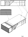
- Fig.1
- eine schematische Gesamtansicht des erfindungsgemäßen mobilen Bildaufnahmestudios in Explosionsdarstellung
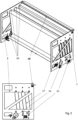
- Fig. 2
- eine schematische Gesamtansicht des erfindungsgemäßen mobilen Bildaufnahmestudios in drei Ansichten
- Fig. 3
- eine schematische Ansicht des Aus- und Einfahrmechanismus
- Fig. 4
- eine schematische Ansicht des Grundkörpers mit eingeklappter Raumsektion ohne Mechanismus der Dachsektion
- Fig. 5
- eine schematische Ansicht des Grundkörpers mit ausgeklappter Raumsektion
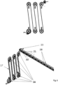
- Fig. 6
- Darstellung der Schlitzschiene
- Das erfindungsgemäße mobile Bildaufnahmestudio für sich soll hier in vier Sektionen (Sektion I bis IV) unterteilt sein.
- Die Einteilung in Sektionen macht die verschiedenen Baugruppen in ihren übergeordneten Funktionen differenzierter und dann so ihre Darstellung einfacher nachvollziehbar. Denn die Aufgabe ist der Transport von größtmöglichem, potenziellen Volumen auf kleinstmöglichem Raum plus Lüftung.
- Sektion I ist als Grundkörper 1 die äußere Form und das Chassis des mobilen Bildaufnahmestudios.
- Wie in
Fig. 1 und4 dargestellt, ist der Grundkörper 1 ein containerförmiges Transportgehäuse und die statische Basis des mobilen Bildaufnahmestudios während des Transport -oder Betriebsmodus. Die anderen Sektionen befinden sich während des Transportmodus im Innern des Grundkörpers 1 verstaut. Darüber hinaus, um den Transport des mobilen Bildaufnahmestudios zu gewährleisten, ist es eine weitere Aufgabe des Grundkörpers 1, die notwendige Statik des sich entfaltenden Bildaufnahmestudios zu gewährleisten. Im Innern, an der Längsseite des Grundkörpers 1 ist der größtmögliche Abstand zum entstehenden Raum. - In der Größe der großen Seitenwand des Grundkörpers 1 befindet sich hier der Monitor 5, beweglich und drehbar verankert.
- Damit das mobile Bildaufnahmestudio auch während des Transports belüftet werden kann, ist die Seitenwand hinter dem Monitor 5 mit beweglichen Lamellen 19, wie in
Fig. 4 zu ersehen, bestückt, damit nach Regen eine Luftzirkulation zum Trocknen der Anlage im Innenraum gewährleistet ist. - Sektion II ist der Aus- und Einfahrmechanismus 2, der die Dachkonstruktion 8 nach dem Gebrauch wieder aufwickelt und gegebenenfalls mit einem Gebläse trocknet. Der Aus- und Einfahrmechanismus 2 bleibt innerhalb das Grundkörpers 1 fest verankert. Das Aus- und Einfahren erfolgt im vorliegenden Ausführungsbeispiel über zwölf Perforationsräder 16, die jeweils mit acht abgerundeten Dornen auf einem Außenring in eine Perforation auf zwei flexiblen Perforationsbändern 17 greifen. Damit werden, von einem Elektromotor 14 angetrieben, die flexiblen Perforationsbänder 17 bewegt, die ab der Hälfte ihrer Länge fest mit der ebenfalls flexiblen Dachkonstruktion 8 jeweils rechts und links verbunden sind. Der Transport mit Motorkraft wird nur beim Verstauen der Dachkonstruktion 8 zurück in den Transportmodus nötig. Das kann geschehen, weil bei der Gegenbewegung, das Entfalten der Dachkonstruktion 8, Lufttanks die erforderliche Bewegung bewerkstelligen. Somit wird die motorgestützte Transportbewegung nur in eine Richtung gebraucht.
- Deshalb sind die Perforationsbänder 17 mit ihrer Perforation doppelt so lang, wie die Länge der Dachkonstruktion 8. So ist der Monitor 5 im Betriebsmodus überhaupt sichtbar und im Transportmodus die Dachkonstruktion 8 trockenbar. Im Transportmodus werden die Perforationsbänder 17 auf federgetriebenen Wickelspulen zwischengelagert. Die Perforationsräder 16 sind so angeordnet, dass zwischen den Flächen der Oberseite bzw. Unterseite der aufgewickelten Dachkonstruktion 8 Platz für die Luftzirkulation beim Trocknen bleibt.
- Sektion III, die Raumsektion 3 ist im Transportmodus eine Seitenwand des Grundkörpers 1 und besteht aus zwei Türflügeln 3a, 3b, wie in
Fig. 4 dargestellt. Im Betriebsmodus sind sie mindestens 90 Grad geöffnet, wie inFig. 5 dargestellt. Die Türflügel 3a, 3b beherbergen Lastschenkel 10, die aufgeklappt den Weg der Kraftaufnahme des Daches 4 senkrecht verlängern. Das entstehende Gestell ist so einerseits für die Stabilität und Statik der betriebsbereiten Anlage zuständig, als auch die universelle Aufnahmekonstruktion jeglichen Filmequipments. Die unteren Außenecken der geöffneten Türflügel 3a, 3b sind mit Stützmodulen 12 versehen, die wie Wagenheber das Gestell vom Untergrund her fixieren. So kann die Last der Dachkonstruktion 8 und die Last des angeflanschten Equipments auf den Boden abgeleitet werden. Im vorliegenden Ausführungsbeispiel als Querrohre ausgebildete Querstreben 11, an der Oberseite der Lastschenkel 10 verbunden, fangen die Horizontalkräfte auf. Das sich aufklappende Gestell muss das Lichtequipment tragen, das notwendig wird, um die Lichtstimmung im Studioraum 7 zu produzieren, die entweder von der virtuellen Kulisse, dem Hintergrund auf dem Monitor 5, vorgegeben oder anderweitig gestaltet gewünscht wird. - Sektion IV, ist die Dachkonstruktion 8, sowie die oberen Ansätze der verbleibenden beiden Seitenwände 9a und 9b und der Rückwand 13 des Studios. Die Oberseite besteht aus einem wasserdichten flexiblen Material, das mit den Lufttanks verklebt ist. Die untere Seite ist schwarz und von stumpfer Oberfläche. Die Seitenwand- und die Rückwandansätze sind im Transportmodus mit Klettverschlüssen an die Dachkonstruktion 8 geheftet. Im Betriebsmodus wird der bis zum Boden fehlende Teil der Studiowände 9a und 9b und der Rückwand 13 durch mitgeführte schwarzreflektierende Stoffe ergänzt und auch mit Klettverschlüssen angeheftet. Wird die Anlage in den Betriebsmodus versetzt geschieht das durch einen Luftkompressor 24, der die flexiblen Lufttanks im Innern der Dachkonstruktion 8 mit Druckluft füllt. Diese Lufttanks sind fest mit der Oberseite sowie der Unterseite verklebt.
- So schiebt die im Verhältnis zu den Oberflächen flexiblere Struktur der Lufttanks den gesamten Dachkörper durch eine Schlitzschiene auf die Außenseite des Grundkörpers 1. Diese Schlitzschiene ist mit Rollen bestückt, um die Reibung während des Vorgangs zu reduzieren.
- Die Schlitzschiene 18 besteht aus zwei U-Trägern 20, die gegenüberliegend Schlittenchassis 21 stabilisieren. In den Schlittenchassis 21 sind abgerundete Rollzylinder 22 gelagert, die die Reibung 90 Grad zum Transport der Dachkonstruktion 8 montiert, reduzieren. Da Umweltumstände unterschiedliche materielle Zustände der zu transportierenden Dachkonstruktion 8 zur Folge haben, ist die Schlitzschiene 18 oben und unten mit einem als Arretierschraube ausgebildeten Arrettierelement versehen, welches bei Volumenveränderungen der Dachkonstruktion eine Justierung ermöglicht.
- Damit das Dach 4 auch auf der Rückseite des Studios die gleiche Höhe hat, werden sechs der Perforationslöcher für Dachstützen 15 genutzt. Das ist möglich, weil, die im Bereich der Rückwand 13 wirkende Last des Daches 4 an dieser Stelle nur senkrecht wirkt.
- Das Entfalten und Verstauen der Studioanlage kann sowohl im Handbetrieb, als auch mit elektrischer Energie geschehen. Im Falle des Entfaltens können die Lufttanks mit einer Handluftpumpe befüllt werden. Mit einer Handkurbel kann später der Elektromotor 14 überbrückt und so die Perforationsbänder 17 bewegt werden. Die Stromversorgung des Monitors 5 und seiner Steuereinheit findet über einen Akkumulator statt, der von einem Sonnenkollektor gespeist wird. Darüber hinaus verfügt die Anlage über einen mobilen Generator und einen Elektroanschluss, der eine konventionelle, externe Stromversorgung ermöglicht. So kann die Anlage bei Bedarf autark ohne jede Stromversorgung, unter freiem Himmel betrieben werden. Im Betriebsmodus ist die Anlage entfaltet und der Studioraum 7 zwischen Monitor 5 und Kamera 4 kann für fiktionale oder nichtfiktionale Bildaufnahmen genutzt werden. Die nun von Einflussfaktoren, wie Lichtverhältnisse
oder Wetter unabhängige Fläche des Studioraums 7 hat eine Größe von 11m x 5m. Um wie erwähnt auch Perspektivwechsel der Kamera 4 umsetzen zu können, muss sich der Vordergrund, die Objekte im Studioraum 7 vor der Monitorfläche, physisch an die Kamera 4 anpassen. Das bedeutet, dass auch sehr große, schwere Requisiten, wie z.B. Autos bewegt werden müssen. Deshalb kann im Studioraum eine mitgelieferte Bühnenplattform benutzt werden. Die Plattform kann in verschiedenen Ausführungen für je unterschiedliche Anforderungen benutzt werden. Ein Laufband als Bühnenplattform kann eine relative Bewegung zur Monitorwand kompensieren und so beispielsweise menschliche Laufbewegungen in der Kamera 4 vortäuschen. Durch die räumliche Trennung von Vordergrund und Hintergrund - dem Studioraum 7 und dem Monitor 5 - ist es mit der Anlage auch möglich, eine präzise Interaktion zwischen Beidem möglich zu machen. - Da Unfälle von Fahrzeuge mit mobilen Kameraaufbauten im öffentlichen Straßenverkehr zu Verboten vielerorts geführt haben, ergibt sich ein weiteres Anwendungsgebiet der Erfindung: die Realisierung von Fahraufnahmen in Autos, auf Fahrrädern etc. Der Monitor 5 kann als Hintergrundkulisse für Fahraufnahmen fungieren, indem Fahrzeuge auf Bewegungsimitatoren im vorhandenen Studioraum auf die Bühnenplattform gestellt werden und vorproduzierte Hintergründe auf dem Monitor 5 abgespielt werden. Es müssen dafür nicht mehr ganze Straßenzüge gesperrt werden. Im Studioraum 7, dem Vordergrund befinden sich die Bildobjekte, die relativ zur Monitorwand unbeweglich sind. Die Illusion der Bewegung wird allein durch den sich bewegenden Hintergrund und die Bewegungsimitatoren auf der Bühnenplattform erzeugt.
- An das sich aus Sektion III entfaltende Gestell kann sowohl jede Form von Beleuchtungsequipment, als auch weitere Monitore oder Leinwände für Reflexionen angeflanscht werden. Die Methode, die sich bewegende Umwelt auch in Reflexionen auf Bildobjekten, wie z.B. Autoscheiben der Umgebung, zu imitieren, ist bereits gängige Praxis bei regulären Studioaufbauten für Produktionen von Fahraufnahmen dieser Art in einem festen Studio.
- Die Erfindung ist nicht beschränkt auf die hier dargestellten Ausführungsbeispiele. Vielmehr ist es möglich, durch Kombination und Variation der benannten Mittel und Merkmale weitere Realisierungsvarianten zu realisieren, ohne den Rahmen der Erfindung zu verlassen.
-
- 1
- Grundkörper
- 2
- Aus- und Einfahrmechanismus
- 3
- Raumsektion
- 3a
- Flügeltür
- 3b
- Flügeltür
- 4
- Dach
- 5
- Monitor
- 6
- Kamera
- 7
- Studioraum
- 8
- Dachkonstruktion
- 9a
- Seitenwand
- 9b
- Seitenwand
- 10
- Lastschenkel
- 11
- Querstreben
- 12
- Stützmodule
- 13
- Rückwand
- 14
- Elektromotor
- 15
- Dachstützen
- 16
- Perforationsräder
- 17
- Perforationsbänder
- 18
- Schlitzschiene
- 19
- Lamellen
- 20
- U-Träger
- 21
- Schlittenchassis
- 22
- Rollzylinder
- 23
- Arretierelement
- 24
- Luftkompressor
Claims (10)
- Mobiles Bildaufnahmestudio zur ortsunabhängigen Herstellung von Bildaufnahmen unter Studiobedingungen mit einem Grundkörper (1), in welchem im Transportmodus ein Aus- und Einfahrmechanismus (2) für ein Dach (4) und Türflügel (3a, 3b) angeordnet sind, wobei im Betriebsmodus das Dach (4) entfaltet und die Türflügel (3a, 3b) ausgeklappt sind und zusammen mit dem Innenraum des Grundkörpers (1), Seitenwänden (9a, 9b) und einer Rückwand (13) einen Studioraum (7) bilden.
- Mobiles Bildaufnahmestudio nach Anspruch 1, dadurch gekennzeichnet, dass der Aus- und Einfahrmechanismus (2) im Grundkörper (1) fest verankert ist und Perforationsräder (16) und Perforationsbänder (17) umfasst.
- Mobiles Bildaufnahmestudio nach Anspruch 1, dadurch gekennzeichnet, dass an den Türflügeln (3a, 3b) Lastschenkel (10) angeordnet sind.
- Mobiles Bildaufnahmestudio nach Anspruch 3, dadurch gekennzeichnet, dass die Lastschenkel (10) mit als Querrohre ausgebildeten Querstreben (11) verbunden sind.
- Mobiles Bildaufnahmestudio nach Anspruch 1, dadurch gekennzeichnet, dass in dem Grundkörper (1) mindestens ein Monitor (5) und in dem Studioraum (7) mindestens eine Kamera (6) angeordnet ist.
- Mobiles Bildaufnahmestudio nach mindestens einem der voranstehenden Ansprüche , dadurch gekennzeichnet, dass die Seitenwand hinter dem Monitor (5) bewegliche Lamellen (19) zur Realisierung einer Luftzirkulation zum Trocknen der Anlage aufweist.
- Mobiles Bildaufnahmestudio nach mindestens einem der voranstehenden Ansprüche , dadurch gekennzeichnet, dass das das Dach (4) eine Dachkonstruktion (8) umfasst, die mit Lufttanks verbunden ist.
- Mobiles Bildaufnahmestudio nach Anspruch 1, dadurch gekennzeichnet, dass im Studioraum (7) eine Bühnenplattform angeordnet ist.
- Verfahren zur ortsunabhängigen Herstellung von Bildaufnahmen unter Studiobedingungen in einem mobilen Bildaufnahmestudio, wobei die Kamera ausschließlich auf die Monitorwand ausgerichtet wird und durch einen festgelegten Winkel zu dem Hintergrundmonitor gebunden ist, wobei wenn sich die Perspektive der Kamera ändern soll, nicht wie üblich die Position und Richtung der Kamera geändert wird, sondern der Hintergrund auf dem Monitor und die Positionen der Objekte, die sich vor der Kamera befinden und aufgenommen werden sollen, werden entsprechend neu geordnet.
- Verfahren nach Anspruch 6, dadurch gekennzeichnet, dass die Kamera jede Position des Studioraumes einnehmen kann, solange sie auf den Monitor gerichtet bleibt.
Applications Claiming Priority (1)
| Application Number | Priority Date | Filing Date | Title |
|---|---|---|---|
| DE102022131909.1A DE102022131909B3 (de) | 2022-12-01 | 2022-12-01 | Mobiles Bildaufnahmestudio |
Publications (1)
| Publication Number | Publication Date |
|---|---|
| EP4378756A1 true EP4378756A1 (de) | 2024-06-05 |
Family
ID=88839299
Family Applications (1)
| Application Number | Title | Priority Date | Filing Date |
|---|---|---|---|
| EP23210650.0A Pending EP4378756A1 (de) | 2022-12-01 | 2023-11-17 | Mobiles bildaufnahmestudio und verfahren zur bildaufnahme |
Country Status (2)
| Country | Link |
|---|---|
| EP (1) | EP4378756A1 (de) |
| DE (1) | DE102022131909B3 (de) |
Citations (8)
| Publication number | Priority date | Publication date | Assignee | Title |
|---|---|---|---|---|
| US1417736A (en) * | 1921-07-05 | 1922-05-30 | Heygate Eva Constance | Movable bungalow |
| DE2032594A1 (de) | 1970-07-01 | 1972-01-05 | Bavaria Atelier Gmbh | Verfahren und Anordnung zur Film- und Fernsehaufnahme eines Realbildes in Kombination mit einem aufprojizierten Projektionsbild |
| US5478129A (en) * | 1992-10-22 | 1995-12-26 | Kinoshita & Iwahashi | Movable photo vehicle |
| US20110242322A1 (en) | 2008-12-02 | 2011-10-06 | Musion Ip Limited | Mobile studio |
| WO2016059666A1 (ja) * | 2014-10-14 | 2016-04-21 | 東京リスマチック株式会社 | スタジオおよびスタジオ付車両 |
| EP3269591B1 (de) | 2015-03-09 | 2019-01-09 | Hitachi Kokusai Electric Inc. | Mobiles bordstudio und verfahren zur herstellung eines damit ausgestatteten fahrzeugs |
| US20190011806A1 (en) * | 2017-07-07 | 2019-01-10 | George Zilban | Mobile photography studio |
| CN113810612A (zh) * | 2021-09-17 | 2021-12-17 | 上海傲驰广告文化集团有限公司 | 一种模拟化实景拍摄方法及系统 |
Family Cites Families (4)
| Publication number | Priority date | Publication date | Assignee | Title |
|---|---|---|---|---|
| DE202010017591U1 (de) | 2010-02-15 | 2012-03-06 | Florin Nagler | Gebäude mit Transportcontainer und Zeltanbau |
| BR102019006465A2 (pt) | 2019-03-29 | 2020-10-13 | Globo Comunicação E Participações S.a. | Sistema e método de captação e projeção de imagem, e, uso do sistema. |
| US11159748B1 (en) | 2020-07-14 | 2021-10-26 | Guy Cohen Paz | Studio in a box |
| DE102020119601A1 (de) | 2020-07-24 | 2022-01-27 | Arnold & Richter Cine Technik Gmbh & Co. Betriebs Kg | Hintergrundwiedergabesystem |
-
2022
- 2022-12-01 DE DE102022131909.1A patent/DE102022131909B3/de active Active
-
2023
- 2023-11-17 EP EP23210650.0A patent/EP4378756A1/de active Pending
Patent Citations (8)
| Publication number | Priority date | Publication date | Assignee | Title |
|---|---|---|---|---|
| US1417736A (en) * | 1921-07-05 | 1922-05-30 | Heygate Eva Constance | Movable bungalow |
| DE2032594A1 (de) | 1970-07-01 | 1972-01-05 | Bavaria Atelier Gmbh | Verfahren und Anordnung zur Film- und Fernsehaufnahme eines Realbildes in Kombination mit einem aufprojizierten Projektionsbild |
| US5478129A (en) * | 1992-10-22 | 1995-12-26 | Kinoshita & Iwahashi | Movable photo vehicle |
| US20110242322A1 (en) | 2008-12-02 | 2011-10-06 | Musion Ip Limited | Mobile studio |
| WO2016059666A1 (ja) * | 2014-10-14 | 2016-04-21 | 東京リスマチック株式会社 | スタジオおよびスタジオ付車両 |
| EP3269591B1 (de) | 2015-03-09 | 2019-01-09 | Hitachi Kokusai Electric Inc. | Mobiles bordstudio und verfahren zur herstellung eines damit ausgestatteten fahrzeugs |
| US20190011806A1 (en) * | 2017-07-07 | 2019-01-10 | George Zilban | Mobile photography studio |
| CN113810612A (zh) * | 2021-09-17 | 2021-12-17 | 上海傲驰广告文化集团有限公司 | 一种模拟化实景拍摄方法及系统 |
Also Published As
| Publication number | Publication date |
|---|---|
| DE102022131909B3 (de) | 2024-03-28 |
Similar Documents
| Publication | Publication Date | Title |
|---|---|---|
| DE3872355T2 (de) | Mobileinheit fuer ausstellungen. | |
| EP0799436B2 (de) | Verwendung eines bildprojektors zum darstellen sich bewegender bilder im hintergrund einer bühne | |
| DE69609155T2 (de) | Anhänger mit ausklappbarer Bühne | |
| EP1922710B1 (de) | Transportable grossbildleinwand | |
| DE102022131909B3 (de) | Mobiles Bildaufnahmestudio | |
| EP1229188B1 (de) | Container | |
| EP1430465B1 (de) | Werbeträger | |
| EP4148497B1 (de) | Filmvorführvorrichtung | |
| DE69503878T2 (de) | In eine Bühne umwandelbarer Anhänger | |
| DE19704773A1 (de) | Fluggerät mit einer Hülle | |
| EP0866187A1 (de) | Mobiles Gebäude | |
| DE3443840A1 (de) | Reflexwand fuer photographische zwecke | |
| DE4435582C1 (de) | Einrichtung zum Abgrenzen eines Raumes | |
| AT506736B1 (de) | Transportabler werbeträger | |
| DE436835C (de) | Schwimmendes Reklamefahrzeug mit hoch ueber Deck hinausragender Projektionseinrichtung | |
| DE202024000419U1 (de) | Abstellvorrichtung | |
| DE602004001749T2 (de) | Umzugssystem | |
| DE102022117600A1 (de) | Mobiles Container-Raumsystem | |
| AT517565B1 (de) | Aufnahmekabine | |
| DE1800199C (de) | Fahrbare Kabine mit seitlich vergrößerbarem Kabinenmittelteil | |
| DE311539C (de) | ||
| DE1915079B2 (de) | Bildvorführwagen | |
| DE1906091A1 (de) | Traglufthalle zu Projektionszwecken | |
| DE7827021U1 (de) | Mobile ballonhalle | |
| DE202006008919U1 (de) | Transportable Präsentationsvorrichtung |
Legal Events
| Date | Code | Title | Description |
|---|---|---|---|
| PUAI | Public reference made under article 153(3) epc to a published international application that has entered the european phase |
Free format text: ORIGINAL CODE: 0009012 |
|
| STAA | Information on the status of an ep patent application or granted ep patent |
Free format text: STATUS: THE APPLICATION HAS BEEN PUBLISHED |
|
| AK | Designated contracting states |
Kind code of ref document: A1 Designated state(s): AL AT BE BG CH CY CZ DE DK EE ES FI FR GB GR HR HU IE IS IT LI LT LU LV MC ME MK MT NL NO PL PT RO RS SE SI SK SM TR |
|
| STAA | Information on the status of an ep patent application or granted ep patent |
Free format text: STATUS: REQUEST FOR EXAMINATION WAS MADE |
|
| 17P | Request for examination filed |
Effective date: 20241205 |
|
| STAA | Information on the status of an ep patent application or granted ep patent |
Free format text: STATUS: EXAMINATION IS IN PROGRESS |