EP4375504A2 - Mikrokolbenpumpe - Google Patents
Mikrokolbenpumpe Download PDFInfo
- Publication number
- EP4375504A2 EP4375504A2 EP24169672.3A EP24169672A EP4375504A2 EP 4375504 A2 EP4375504 A2 EP 4375504A2 EP 24169672 A EP24169672 A EP 24169672A EP 4375504 A2 EP4375504 A2 EP 4375504A2
- Authority
- EP
- European Patent Office
- Prior art keywords
- piston
- piston pump
- pump chamber
- side port
- fluid
- Prior art date
- Legal status (The legal status is an assumption and is not a legal conclusion. Google has not performed a legal analysis and makes no representation as to the accuracy of the status listed.)
- Granted
Links
Images


Classifications
-
- F—MECHANICAL ENGINEERING; LIGHTING; HEATING; WEAPONS; BLASTING
- F04—POSITIVE - DISPLACEMENT MACHINES FOR LIQUIDS; PUMPS FOR LIQUIDS OR ELASTIC FLUIDS
- F04B—POSITIVE-DISPLACEMENT MACHINES FOR LIQUIDS; PUMPS
- F04B1/00—Multi-cylinder machines or pumps characterised by number or arrangement of cylinders
- F04B1/02—Multi-cylinder machines or pumps characterised by number or arrangement of cylinders having two cylinders
-
- F—MECHANICAL ENGINEERING; LIGHTING; HEATING; WEAPONS; BLASTING
- F04—POSITIVE - DISPLACEMENT MACHINES FOR LIQUIDS; PUMPS FOR LIQUIDS OR ELASTIC FLUIDS
- F04B—POSITIVE-DISPLACEMENT MACHINES FOR LIQUIDS; PUMPS
- F04B1/00—Multi-cylinder machines or pumps characterised by number or arrangement of cylinders
- F04B1/04—Multi-cylinder machines or pumps characterised by number or arrangement of cylinders having cylinders in star- or fan-arrangement
- F04B1/0404—Details or component parts
- F04B1/0452—Distribution members, e.g. valves
-
- F—MECHANICAL ENGINEERING; LIGHTING; HEATING; WEAPONS; BLASTING
- F04—POSITIVE - DISPLACEMENT MACHINES FOR LIQUIDS; PUMPS FOR LIQUIDS OR ELASTIC FLUIDS
- F04B—POSITIVE-DISPLACEMENT MACHINES FOR LIQUIDS; PUMPS
- F04B1/00—Multi-cylinder machines or pumps characterised by number or arrangement of cylinders
- F04B1/04—Multi-cylinder machines or pumps characterised by number or arrangement of cylinders having cylinders in star- or fan-arrangement
- F04B1/047—Multi-cylinder machines or pumps characterised by number or arrangement of cylinders having cylinders in star- or fan-arrangement with actuating or actuated elements at the outer ends of the cylinders
-
- F—MECHANICAL ENGINEERING; LIGHTING; HEATING; WEAPONS; BLASTING
- F04—POSITIVE - DISPLACEMENT MACHINES FOR LIQUIDS; PUMPS FOR LIQUIDS OR ELASTIC FLUIDS
- F04B—POSITIVE-DISPLACEMENT MACHINES FOR LIQUIDS; PUMPS
- F04B19/00—Machines or pumps having pertinent characteristics not provided for in, or of interest apart from, groups F04B1/00 - F04B17/00
- F04B19/006—Micropumps
-
- F—MECHANICAL ENGINEERING; LIGHTING; HEATING; WEAPONS; BLASTING
- F04—POSITIVE - DISPLACEMENT MACHINES FOR LIQUIDS; PUMPS FOR LIQUIDS OR ELASTIC FLUIDS
- F04B—POSITIVE-DISPLACEMENT MACHINES FOR LIQUIDS; PUMPS
- F04B53/00—Component parts, details or accessories not provided for in, or of interest apart from, groups F04B1/00 - F04B23/00 or F04B39/00 - F04B47/00
- F04B53/10—Valves; Arrangement of valves
- F04B53/109—Valves; Arrangement of valves inlet and outlet valve forming one unit
-
- F—MECHANICAL ENGINEERING; LIGHTING; HEATING; WEAPONS; BLASTING
- F04—POSITIVE - DISPLACEMENT MACHINES FOR LIQUIDS; PUMPS FOR LIQUIDS OR ELASTIC FLUIDS
- F04B—POSITIVE-DISPLACEMENT MACHINES FOR LIQUIDS; PUMPS
- F04B7/00—Piston machines or pumps characterised by having positively-driven valving
- F04B7/0019—Piston machines or pumps characterised by having positively-driven valving a common distribution member forming a single discharge distributor for a plurality of pumping chambers
- F04B7/0026—Piston machines or pumps characterised by having positively-driven valving a common distribution member forming a single discharge distributor for a plurality of pumping chambers and having an oscillating movement
-
- F—MECHANICAL ENGINEERING; LIGHTING; HEATING; WEAPONS; BLASTING
- F04—POSITIVE - DISPLACEMENT MACHINES FOR LIQUIDS; PUMPS FOR LIQUIDS OR ELASTIC FLUIDS
- F04B—POSITIVE-DISPLACEMENT MACHINES FOR LIQUIDS; PUMPS
- F04B7/00—Piston machines or pumps characterised by having positively-driven valving
- F04B7/0042—Piston machines or pumps characterised by having positively-driven valving with specific kinematics of the distribution member
- F04B7/0049—Piston machines or pumps characterised by having positively-driven valving with specific kinematics of the distribution member for oscillating distribution members
-
- F—MECHANICAL ENGINEERING; LIGHTING; HEATING; WEAPONS; BLASTING
- F04—POSITIVE - DISPLACEMENT MACHINES FOR LIQUIDS; PUMPS FOR LIQUIDS OR ELASTIC FLUIDS
- F04B—POSITIVE-DISPLACEMENT MACHINES FOR LIQUIDS; PUMPS
- F04B7/00—Piston machines or pumps characterised by having positively-driven valving
- F04B7/0042—Piston machines or pumps characterised by having positively-driven valving with specific kinematics of the distribution member
- F04B7/0053—Piston machines or pumps characterised by having positively-driven valving with specific kinematics of the distribution member for reciprocating distribution members
-
- F—MECHANICAL ENGINEERING; LIGHTING; HEATING; WEAPONS; BLASTING
- F04—POSITIVE - DISPLACEMENT MACHINES FOR LIQUIDS; PUMPS FOR LIQUIDS OR ELASTIC FLUIDS
- F04B—POSITIVE-DISPLACEMENT MACHINES FOR LIQUIDS; PUMPS
- F04B7/00—Piston machines or pumps characterised by having positively-driven valving
- F04B7/0084—Component parts or details specially adapted therefor
- F04B7/0088—Sealing arrangements between the distribution members and the housing
- F04B7/0096—Sealing arrangements between the distribution members and the housing for pipe-type distribution members
Definitions
- Embodiments generally relate to medication delivery. More particularly, embodiments relate to micro piston pump systems for delivering a liquid drug to a user.
- Many conventional drug delivery devices include a rigid reservoir for storing a liquid drug.
- a drive mechanism is operated to expel the stored liquid drug from the reservoir for delivery to a user.
- Many conventional drive mechanisms use a plunger to expel the liquid drug from a rigid reservoir. Since the plunger must have a length approximately equal to the length of the reservoir, the total length of the drive mechanism and reservoir can be about twice the length of the reservoir. As a result, many conventional drug delivery devices must be made larger to accommodate the reservoir and plunger, often leading to a bulky device that is uncomfortable for the user to wear.
- This disclosure presents various systems, components, and methods related to drug delivery devices. Each of the systems, components, and methods disclosed herein provides one or more advantages over conventional systems, components, and methods.
- Various embodiments include a low-force, non-displacement, micro/miniature valve and/or pump assembly.
- Various embodiments provide a two position, four-way ported valve and/or pump assembly connecting two pump chambers alternatively to an inlet and an outlet of a valve body. Fluid can be drawn in and pushed out of piston pump chambers based on each actuation of the pistons. Other embodiments are disclosed and described.
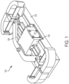
- FIG. 1 illustrates an exemplary pump assembly or system 100.
- the pump assembly 100 can be a micro pump assembly as described herein.
- FIG. 1 shows an isometric view of the pump assembly 100.
- the pump assembly 100 can include a pump base 102, a fluid path assembly (or fluid path components assembly) 104, and an actuator linkage component 106.
- the pump base 102 can support the fluid path assembly 104 and the actuator linkage 106.
- the pump base 102 can be a lead frame injection molded plastic component.
- the pump base 102 can include electrical contacts as described herein.
- the fluid path assembly 104 can include multiple components described further herein.
- the fluid path assembly 104 can include a micro piston pump block (e.g., see FIG. 2 , piston pump block 206).
- the piston pump block can rest or be seated on the pump base 102.
- the piston pump block can be formed as an integral component of the pump base 102.
- the piston pump block can be formed as a separate component from the pump base 102.
- the actuator linkage 106 can be formed of stamped metal or can be an injection molded assembly.
- the actuator linkage 106 can be formed from one or more components.
- the actuator linkage 105 can include multiple hinged or otherwise connected components.
- the actuator linkage 106 can couple the sides of the fluid path assembly 104 to facilitate operation of the pump assembly 100 (e.g., to coordinate actuation of the pistons of the pump assembly 100) as described further herein.
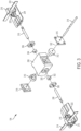
- FIG. 2 illustrates an exploded view of the pump assembly 100.
- the fluid path assembly 104 can include a first piston plate 202, a second piston plate 204, a piston pump block (or valve body) 206, a first piston 208, and a second piston 210.
- the first piston 208 can be positioned between the piston pump block 206 and the first piston plate 202 and coupled thereto.
- the second piston 210 can be positioned between the piston pump block 206 and the second piston plate 204 and coupled thereto.
- the piston pump block 206 can be formed from micro injection molded plastic.
- the pistons 208 and 210 can each be formed from precision drawn wire or ground stock.
- the first piston plate 202 can include a first component or block 212 that supports a bi-stable element 214 (e.g., a bi-stable spring).
- the first piston plate 202 can further include a second component 216 that can provide coupling to a first end of the actuator linkage 106.
- the first component 212 and the second component 216 can each be raised portions or extensions of the first piston plate 202.
- the second piston plate 204 can include a third component or block 218 that supports a bi-stable element 220 (e.g., a bi-stable spring).
- the second piston plate 204 can further include a fourth component 222 that can provide coupling to a second end of the actuator linkage 106.
- each piston plate 202 and 204 can be a stamped metal plate having the integral bi-stable springs 214 and 220 (e.g., extending outward and/or away from the extension components 212 and 218).
- each piston plate 202 and 204 can be an over-molded component enclosing a bi-stable element 214 and 220, respectively.
- the piston plate 202, the first component 212, the second component 216, and the bi-stable element 214 can be integrally formed (e.g., as part of a single, unitary piece of component).
- these constituent components can be formed together through injection molding. Under such a scenario, these constituent components can be considered to be a first piston assembly or portion thereof (e.g., including the piston 208)
- the piston plate 204, the first component 218, the second component 222, and the bi-stable element 220 can be integrally formed (e.g., as part of a single, unitary piece of component).
- these constituent components can be formed together through injection molding. Under such a scenario, these constituent components can be considered to be a second piston assembly or portion thereof (e.g., including the piston 210).
- the pump base 102 can include a base component 224 on which the piston pump block 206 and the pistons plates 202 and 204 can rest and/or be positioned on.
- the pump base 102 can further include a first arm or extension 226 and a second arm or extension 228.
- the first and second arm extensions 226 and 228 can be positioned at opposite ends of the pump base 102.
- the first extension 226 can be coupled to and/or can support the bi-stable spring 214.
- the second extension 228 can be coupled to and/or can support the bi-stable spring 220.
- the first and second arm extensions 226 and 228 can be positioned closer to a center of the pump base 102.
- the piston pump block 206 can remain in a stationary position during operation while the piston plates 202 and 204 can move back and forth in the directions shown by indicator 230 along the base 224.
- the pump base 102 can include a first stop 232 and a second stop 234.
- the first and second stops 232 and 234 can engage the pistons 208 and 210, respectively, as they move in the back and forth directions 230.
- the stops 232 and 234 can limit a maximum displacement of the pistons 208 and 210, respectively.
- the stops 232 and 234 can be conductive and can operate as electrical contacts, such that a position of the pistons 208 and 210 can be detected based on contact with the stop 232 or 234.
- the actuator linkage 106 can be coupled to the extension 216 and the extension 222.
- the actuator linkage 106 can ensure coordinated operation and/or movement of the pistons 208 and 210 by ensuring the piston plates 202 and 204 move together (e.g., in unison in the same direction at the same time).
- the actuator linkage 106 can also be coupled to the piston pump block 206 (e.g., along any portion of the top of the piston pump block 206).
- the pistons 208 and 210 can be moved separately and/or independently to enable sequential actuation or movement of the pistons 208 and 210.
- FIG. 3 illustrates an exploded view of the fluid path assembly 104.
- the fluid path assembly 104 can further include a first piston seal 302 and a second piston seal 304.
- the piston seals 302 and 304 can be positioned within open areas of the piston pump block 206.
- the piston seals 302 and 304 can be formed by injection molded liquid silicone rubber.
- the fluid path assembly 104 can further include a first piston seal retainer 306 and a second piston seal retainer 308.
- the piston seal retainers 306 and 308 can be formed of injection molded plastic, can fit into open areas of the piston pump block 206, and can press or fit the piston seals 302 and 304 into proper position.
- the piston seal retainers 306 and 308 can be formed by deforming portions of the piston pump block 206 - for example, by crushing, heat staking, or otherwise deforming material forming the block 206 to create a retaining feature or component (and/or to provide the retaining functions of the retainers 306 and 308).
- the fluid path assembly 104 can further include a first needle septum 310 and a second needle septum 312.
- the septa 310 and 312 can be cross ported and can be positioned or fitted into open areas of the piston pump block 206.
- a first needle valve seal retainer 314 and a second needle valve seal retainer 316 can be pressed or fitted into open areas of the piston pump block to maintain proper positioning or fit of the septa 310 and 312, respectively.
- the fluid path assembly 104 can also include a side slit cannula (or side port needle or tube component) 318.
- the cannula 318 can be positioned through the retainers 314 and 316, the septa 310 and 312, and the piston pump block 206.
- the pistons 208 and 210 can be positioned through the seal retainers 306 and 308 and the piston seals 302 and 304, respectively, as well as partially positioned within the piston pump block 206.
- FIG. 3 further illustrates a first central axis 320 and a second central axis 322.
- the first central axis 320 and the second central axis 322 can be perpendicular to one another.
- the components shown in FIG. 3 can be aligned relative to the first central axis 320 and/or the second central axis 322 as shown.
- the tube component 318 can be aligned with respect to the second central axis 322 as shown.
- the tube component 318 can move in directions parallel to the second central axis 322 as described herein.
- the first and second pistons 208 and 210 can be aligned with respect to the first central axis 320 as shown.
- the first and second pistons 208 and 210 can move in directions parallel to the first central axis 320 as described herein.
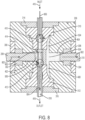
- FIG. 4 illustrates an overhead cross-sectional view of a portion of the fluid path assembly 104.
- FIG. 4 shows the components operating within and/or directly coupled to the piston pump block 206 (e.g., all portions of the fluid path assembly other than the plates 202 and 204).
- the tube component 318 can be positioned within an opening or slot (or channel) of the pump block 206 and openings or slots (or channels) of the septa 310 and 312.
- the tube component 318 can include a first opening or side port (or side slit) 410, a second opening or side port (or side slit) 412, and a center plug 414.
- the tube component 318 can be a rigid tubing placed into the valve body 206.
- the piston pump block 206 can also be referred to as a pump block.
- the center plug 414 can be installed into the tube component 318 as a separate piece or component from the tube component 318 or can be formed through a spot-weld crimp, swage, or crushing process.
- a first portion of the tube component 318 (including a first end) can be or can form an inlet component 416 of the tube component 318.
- a second portion of the tube component 318 (including a second end) can be or can form an outlet component 418 of the tube component 318.
- the center plug 414 can help prevent fluid (e.g., a liquid drug) from flowing directly between the inlet component 416 and the outlet component 418 (e.g., can separate the inlet and outlet components 416 and 418).
- fluid e.g., a liquid drug
- the inlet component 416 can be coupled to a reservoir storing a liquid drug or other therapeutic agent and the outlet component 418 can be coupled to a fluid path component (e.g., a cannula) coupled to a patient.
- the septa 310 and 312 can be formed from liquid silicone rubber or other compatible elastomeric material.
- the septa 310 and 312 can each be formed (e.g., molded) as a single component or piece or as multiple components or pieces.
- the septa 310 and 312 can each be pierced by the tube component 318.
- the tube component 318 can be moved along directions shown by indicator 420 (e.g., up and down relative to the orientation of the components depicted in FIG. 4 ).
- the septa 310 and 312 can be aligned as shown (see FIG. 3 ).
- the piston 208 can be positioned within a first piston pump chamber 402.
- the piston 210 can be positioned within a second piston pump chamber 404.
- the first and second piston pump chambers 402 and 404 can be open areas within the valve body 206.
- the first and second pistons 208 and 210 can be moved (e.g., linearly) within the first piston pump chamber 402 and the second piston pump chamber 404, respectively, along directions shown by indicator 422. In various embodiments, the directions 402 and 422 can be perpendicular to one another.
- the arrangement of the components of the fluid path assembly 104 shown in FIG. 4 can form a low force, non-displacement, micro/miniature valve or valve system.
- the valve system can provide a cross-flow valve that provide a two position, four-way ported valve that can alternatively connect the pump chambers 402 and 404 to the inlet component 416 and the outlet component 418 of the pump block 206.
- other means or components for positioning the seals 302 and 304 and/or the sept 310 and 312 can be used such that retainers 306 and 308 and/or retainers 314 and 316 are not used or included.
- the septa 310 and 312 can form radial seals with the pump block 206.
- the septa 310 and 312 can each include two radial sealing faces to the pump block 206 separated with an opening or through-hole (e.g., a void) where no seal to the tube component 318 is provided.
- the voids can create openings that can provide fluid channels to the tube component 318.
- the septa 310 and 312 can also form faces seals with the pump block 206.
- the pump block 206 can include a first fluid channel 406 and a second fluid channel 408.
- the fluid channel 406 and the piston chamber 402 can be coupled to the inlet component 416 (e.g., by way of the port 410) or coupled to the outlet component 418 (e.g., by way of the port 412) based on the position of the tube component 318.
- the fluid channel 408 and the piston chamber 404 can be coupled to the inlet component 416 (e.g., by way of the port 410 and the cross-porting feature of septa 310; see FIGs. 14A and 14B ) or the outlet component 418 (e.g., by way of the port 412 and the cross-porting feature of septa 312; see FIGs. 14A and 14B ) based on the position of the tube component 318.
- the first channel 406 is shorter than the second channel 408 and can extend to front portions of the septa 310 and 312 while the second channel 408 can extend to middle sections of the septa 310 and 312, but neither are so limited.
- the valve system depicted in FIG. 4 can operate by moving the tube component 318 to certain positions along the septa 310 and 312 and subsequently moving the pistons 208 and 210, thereby coupling the pistons 208 and 210 to the inlet component 416 and outlet components 418 in a manner that causes fluid to be pumped into or out of the pump block 206 during each stroke of the pistons 206 and 208.
- a first annular fluid chamber 424 and a second annular fluid chamber 426 can be coupled to the channel 408.
- the annular chambers 424 and 426 can be positioned around a portion (e.g., middle portion) of the septa 310 and 312 as shown.
- the annular chamber 424 can allow fluid to flow through the septa 310 and into the chamber 404 or allow fluid to flow from the chamber 404 through the septa 312.
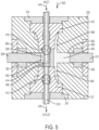
- FIGs. 5-8 illustrate operation of the components of the fluid path assembly 104 depicted in FIG. 4 .
- FIGs. 5-8 illustrate a sequence of operations for drawing in fluid to the piston chambers 402 and 404 from the inlet component 416 and pumping the fluid out of the piston chambers 402 and 404 through the outlet component 418.
- the inlet component 416 can be coupled to a reservoir storing a liquid drug and the outlet component 418 can be coupled to a fluid path component that is coupled to a user (e.g., a cannula).
- FIG. 5 illustrates a first stage or initial stage of operation.
- the tube component 318 can be actuated to move in a direction 502 (e.g., toward the septum 312) to set the side ports 410 and 412 into appropriate positions for valving (e.g., a stroke of the pistons 208 and 210).
- the tube component 318 can be moved to position the side port 410 (e.g., the side port connected to the inlet component 416) to be coupled to the piston chamber 402.
- the side port 412 e.g., the side port coupled to the outlet component 418) can be positioned to be coupled the piston chamber 404.
- a first fluid region is shown by indicator 504 and a separate second fluid region is shown by indicator 506.
- a first portion of the fluid from the reservoir coupled to the inlet component 416 can be positioned within the pump chamber 404 and/or within the first fluid region 504.
- the pump chamber 402 can be empty or devoid of any of the fluid and/or can include a second portion of the fluid (e.g., within the second fluid region 506).
- FIG. 6 illustrates a second stage of operation (e.g., subsequent to the stage of operation depicted in FIG. 5 ).
- the pistons 208 and 210 can both be actuated (e.g., in unison) to move in a direction 602.
- fluid can be pushed out of the pump chamber 404, through the septum 312 (e.g., through the side port of the septum 312), through the side port 412, and then out through the outlet component 418 (e.g., for delivery to a patient) - as indicated by flow arrows 604.
- fluid from the reservoir coupled to the inlet component 416 can be drawn in from the inlet component 416 to the pump chamber 402 by way of the side port 410 - as indicated by flow arrows 606.
- the indicator 504 shows the first fluid region associated with the pump chamber 404 and the indicator 506 shows the second fluid region associated with the pump chamber 402.
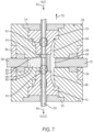
- FIG. 7 illustrates a third stage of operation (subsequent to the stage of operation depicted in FIG. 6 ).
- the tube component 318 is actuated to move in a direction 702 (e.g., toward the septum 310).
- the tube component 318 is moved to couple the side port 410 to the piston chamber 404.
- the side port 412 is coupled to the piston chamber 402.
- the indicator 504 again shows the first fluid region associated with the pump chamber 404 and the indicator 506 shows the second fluid region associated with the pump chamber 402.
- FIG. 8 illustrates a fourth stage of operation (subsequent to the stage of operation depicted in FIG. 7 ).
- the pistons 208 and 210 are both actuated (e.g., in unison) to move in a direction 802.
- fluid can be pushed out of the pump chamber 402, through the side port 412, and then out through the outlet component 418 (e.g., for delivery to a patient) - as indicated by flow arrows 804.
- fluid from the reservoir coupled to the inlet component 416 can be drawn in from the inlet component 416 to the pump chamber 404 - as indicated by flow arrows 806.
- the indicator 504 again shows the first fluid region associated with the pump chamber 404 and the indicator 506 shows the second fluid region associated with the pump chamber 402.
- valve system depicted in FIG. 4 can be operated to draw in a portion of a liquid drug and to expel a portion of the liquid on each piston stroke (e.g., each movement of the pistons 208 and 210) by adjusting a positing of the tube component 318 between each stroke.
- fluid can be either drawn into the pump chamber 402 and pushed out of the pump chamber 404 or can be pushed out of the pump chamber 402 and drawn into the pump chamber 404.
- the sequence of operations e.g., operational states depicted in FIGs.
- 5-8 can be repeated to implement a subsequent cycle of drawing in the fluid through the inlet component 416 from the reservoir and pushing the fluid out through the outlet component 418 for delivery to a patient.
- the sequence of operations can be repeated any number of times to deliver any size of dose of the fluid to the user.
- FIGs. 9-12 illustrate operation of the overall pump assembly 100 for drawing in and pumping out a liquid drug for delivery to a patient.
- the sequence of operations and operational states shown in FIGs. 9-12 can correspond to those shown in FIGs. 5-8 for the depicted components of the fluid path assembly 104.
- FIGs. 9-12 in particular show the interaction of the actuator linkage 106 with the fluid path assembly 104 and the base 102 during actuation of the tube component 318 and the pistons 208 and 210.
- FIGs. 9-12 show overhead views of the pump assembly.
- FIG. 9 illustrates a first stage or initial stage of operation of the pump assembly 100.
- This first operational state can correspond to the operational state of the components depicted in FIG. 5 .
- the tube component 318 (and corresponding, the side ports 410 and 412) is positioned in a manner corresponding to the positioning of the tube component 318 as shown in FIG. 5 (e.g., shifted toward septum 316).
- a conductive travel stop component e.g., similar to stop components 232 and 234; not shown in FIG. 9 for simplicity
- pistons 208 and 210 are positioned to the right (corresponding to the orientation of the pump assembly 100 as depicted in FIG. 9 ) - for example, nearer the arm 228. Accordingly, the piston plates 202 and 204 are shifted off-center to the right most travel position.
- a first arm or end (a left arm corresponding to the orientation of the pump assembly 100 as depicted in FIG. 9 ; e.g., nearer the plate 202) 902 of the actuator linkage 105 can be coupled to the protrusion 216 of the plate 202.
- a second arm or end (a right arm corresponding to the orientation of the pump assembly 100 as depicted in FIG. 9 ; nearer the plate 204) 904 of the actuator linkage 106 can be coupled to the protrusion 222 of the plate 204.
- the actuator linkage 106 is also correspondingly shifted off-center to the right based on the positioning of the plates 202 and 204 (e.g., nearer the arm 228).
- the bi-stable spring 214 is shown coupled to the extension 226 and is shown bent or curved in a first direction (e.g., to the left or toward the arm 226).
- the bi-stable spring 220 is shown coupled to the extension 228 and is shown bent or curved in the same direction as the bi-stable spring 214 (e.g., also to the left or toward the arm 226).
- the bi-stable springs 214 and 220 can initially resist movement of the plates 202 and 204 to the left (e.g., toward the arm 226) until a point of inflection at which point the curvature of the springs 214 and 220 can flip.
- the bi-stable springs 214 and 220 can then help facilitate movement of the plates 202 and 204 to the left.
- the initial resistance of the bi-stable springs 214 and 220 can be used to properly sequence the positioning of the tube 318.
- FIG. 10 illustrates a second stage of operation (subsequent to the stage of operation depicted in FIG. 9 ).
- This second operational state can correspond to the operational state of the components depicted in FIG. 6 .
- the plates 202 and 204 are moved in a direction 1002 (e.g., toward the arm 226; corresponding to the movement of the pistons 208 and 210 in the direction 602 as depicted in FIG. 6 ).
- the actuator linkage 106 can ensure the plates 202 and 204 move in unison.
- the plates 202 and 204 can be actuated in response to actuation of the pistons 208 and 210, respectively.
- the pistons 208 and 210 can be actuated to a point where the states of the bi-stable springs 214 and 220 as shown in FIG. 9 toggle (i.e., change state) so as to help movement of the pistons in the direction 1002 and to no longer to resist such movement.
- a curve or bend of each bi-stable springs 214 and 220 has changed (e.g., relative to the curve or bend of each bi-stable springs 214 and 220 depicted in FIG. 9 ; now facing toward arm 228) - indicating that the initial stable states of the bi-stable springs 214 and 222 have changed to a second stable state.
- the bi-stable springs 214 and 222 can provide a force to complete movement of the pistons 208 and 210 to the positions shown in FIG. 6 .
- the travel stop 232 (see FIG. 2 ; not shown in FIGs. 9-12 ) can stop further movement of the pistons 208 and 210 in the direction 1002. Further, the travel stop 232 can be electrically coupled to a controller or other electronic device and can indicate when the pistons 208 and 210 have reached their final position (in the direction 1002) based on contact with the piston 208 and/or the plate 202.
- the force of the bi-stable springs 214 and 222 can enable the initial actuation force to be lower.
- FIG. 11 illustrates a third stage of operation (subsequent to the stage of operation depicted in FIG. 10 ).
- This third operational state can correspond to the operational state of the components depicted in FIG. 7 .
- the tube component 318 is moved in a direction 1102 (corresponding to the movement of the tube component 318 in the direction 702 as depicted in FIG. 7 ).
- the plates 202 and 204 remain positioned off-center and to the left side of the base 102 (e.g., closer to the arm 226).
- an actuator of the assembly of the assembly 100 can adjust the position of the tube component 318 prior to driving the linkage 106 and/or the pistons 208 and 210.
- FIG. 12 illustrates a fourth stage of operation (subsequent to the stage of operation depicted in FIG. 10 ).
- This fourth operational state can correspond to the operational state of the components depicted in FIG. 8 .
- the plates 202 and 204 are moved in a direction 1202 (corresponding to the movement of the pistons 208 and 210 in the direction 802 as depicted in FIG. 8 ; toward the arm 228).
- the actuator linkage 106 can ensure the plates 202 and 204 move in unison.
- the plates 202 and 204 can be actuated in response to actuation of the pistons 208 and 210, respectively.
- the pistons 208 and 210 can be actuated to a point where the states of the bi-stable springs 214 and 220 as shown in FIG. 11 toggle (i.e., change state) so as to help movement of the pistons 208 and 210 in the direction 1202 and to no longer to resist such movement.
- a curve or bend of each bi-stable springs 214 and 220 has changed (e.g., relative to the curve or bend of each bi-stable springs 214 and 220 depicted in FIG. 11 ; now facing the arm 226) - indicating that the second stable states of the bi-stable springs 214 and 222 have changed back to the first stable state (e.g., as shown in FIG. 9 ).
- the bi-stable springs 214 and 222 can complete movement of the pistons 208 and 210 to the positions shown in FIG. 8 .
- the travel stop 234 (see FIG. 2 ; not shown in FIGs. 9-12 ) can stop further movement of the pistons 208 and 210 in the direction 1202. Further, the travel stop 234 can be electrically coupled to a controller or other electronic device and can indicate when the pistons 208 and 210 have reached their final position (in the direction 1202; toward the arm 228).
- the sequence of operations depicted in FIGs. 9-12 can be repeated to implement a subsequent cycle of drawing in fluid through the inlet component 416 from a reservoir and pushing the fluid out through the outlet component 418 for delivery to a patient.
- the sequence of operations can be repeated any number of times to deliver any size of dose of a liquid drug to the user.
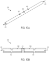
- FIG. 13A illustrates an isometric view of the tube component 318.
- the center plug 414 is positioned between the side port 410 and the side port 412.
- the side port 410 can be coupled to the inlet component 416 and the side port 412 can be coupled to the outlet component 418 as shown.
- the center plug 414 can prevent leaking between the inlet component 416 and the outlet component 418.
- FIG. 13B illustrates a cross-sectional side view of the tube component 318.
- the center plug 414 isolates the inlet component 416 from the outlet component 418.
- the side ports 412 and 414 can be formed, for example, by cross-drilling.
- a first region 1302 between the side port 412 and the center plug 414 can also be filled or filled in (e.g., to form or be coupled to the center plug 414) and/or a second region 1304 between the side port 410 and the center plug 414 can also be filled or filled in (e.g., to form or be coupled to the center plug 414).
- the side ports 410 and 412 can be formed using a grinding method, a laser cutting process, or a machining process, or may be part of the original forming process for the tube component 318 (e.g., by a molding process).
- the center plug 414 can be installed into the tube component 318 as a separate piece or component from the tube component 318 or can be formed through any individual or combination of a spot-weld process, crimping process, swaging process, or filling/plugging process.
- the tube component 318 can be formed of two or more tubes.
- the tube component 318 can be formed of two separate tubes having end caps joined together to form the center plug 414 and capable of moving together as a single component.
- the tube component 318 can be formed of two separate tubes that are not joined.
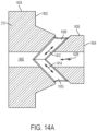
- FIG. 14A illustrates a cross-sectional side view of a first exemplary septum of the pump assembly 100 - for example, the septum 310 depicted in FIG. 3 .
- the septum 310 can include a first face seal 1402 (e.g., to the pump block 206) and a second face seal 1404 (also to the pump block 206).
- the septum 310 can include an inner open area or channel 1406 as well as a first angled opening or channel 1408 and a second angled opening or channel 1410 coupled to the inner channel 1406.
- the tube component 318 can be positioned though the channel 1406 (and/or can pierce through the septum 310 in an area shown by the channel 1406).
- Fluid can flow bidirectionally through the channel 1408 as indicated by flow indicator 1412 into the side ported tube 318 depending on the position of the tube 318.
- fluid can flow bidirectionally through the channel 1410 as indicated by flow indicator 1414 into the side ported tube 318 depending on the position of the tube 318.
- fluid can flow bidirectionally through the channel 1406 as indicated by flow indicator 1428.
- the channels 1408 and 1410 can be coupled to one of the annual fluid chambers 424 or 426 to provide fluid communication with the channel 408. This arrangement can provide the cross ported feature of the septa 310 described herein.
- the septum 310 can further include a first radial seal 1424 (e.g., to the pump block 206) and a second radial seal 1426 (also to the pump block 206).
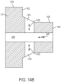
- FIG. 14B illustrates a cross-sectional side view of a second exemplary septum of the pump assembly 100 - for example, the septum 310 depicted in FIG. 3 .
- the exemplary septum depicted in FIG. 14B can include a first straight opening or channel 1416 and a second straight opening or channel 1418 coupled to the inner channel 1406.
- the tube component 318 can be positioned though the channel 1406 (and/or can pierce through the septum 310 in an area shown by the channel 1406). Fluid can flow bidirectionally through the channel 1416 as indicated by flow indicator 1420 into the side ported tube 318 depending on the position of the tube 318.
- fluid can flow bidirectionally through the channel 1418 as indicated by flow indicator 1422 into the side ported tube 318 depending on the position of the tube 318. Fluid can also from through the channel 1406 as shown by the flow indictor 1428. Similar to the arrangement shown in FIG. 14A , the channels 1416 and 1418 provide fluid communication with either the annual fluid chamber 424 or 426 and, in turn, the channel 408.
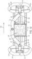
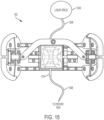
- FIG. 15 illustrates an exemplary arrangement of the pump assembly 100 coupled to a reservoir 1502 and coupled to a user or patient 1504.
- the reservoir 1502 can store any liquid drug or therapeutic agent.
- the reservoir 1502 can be coupled to the inlet component 416 of the tube component 318.
- the reservoir 1502 can be coupled to the inlet component 416 by a fluid path component 1506.
- the fluid path component 1506 can be any type of fluid connection such as a tubing component or other tubing made from any type of suitable material.
- the reservoir 1502 can be a rigid reservoir (e.g., a hard cartridge), a semi-rigid reservoir, or a flexible reservoir (e.g., a bag).
- the user 1504 can be can be coupled to the outlet component 416 of the tube component 318.
- the user 1504 can be coupled to the outlet component 416 by a fluid path component 1508.
- the fluid path component 1508 can be any type of fluid connection such as a tubing component or other tubing made from any type of suitable material.
- the fluid path component 1508 can include a cannula.
- the pump assembly 100 can be used to deliver a liquid drug stored in the reservoir 1502 to the user 1504.
- the pump assembly 100 can be part of or included within a drug delivery device or system including, for example, a wearable drug delivery device.
- the drug delivery device can be a disposable device and can be prefilled with a liquid drug such as, for example, insulin.
- the pump assembly 100 including the valve system depicted in FIG. 4 , can be made small and compact while not sacrificing quality or durability. This enables the embodiments disclosed herein to have a small form factor to enable any device or system in which it is used to also remain small and comfortable to a user. Additionally, the radial sealing used by the valve system depicted in FIG. 4 can provide reliable seals that are not adversely affected by the actuation of the pistons 208 and 210, thereby providing reliable operation on a micro scale.
- the pump assembly 100 and/or any component thereof can be actuated by any suitable means including, for example, using a motor or a shape-memory alloy (SMA) wire actuator.
- the pistons 208 and 210 can be actuated with the other components coupled thereto reacting to the actuation or the arms 226 and 228 or the plates 202 and 204 can be actuated causing components thereto to move in response.
- the actuator linkage 106 and/or the piston plates 202 and 204 can be alternatively actuated to initiate movement.
- FIG. 16 illustrates an exemplary method of operation 1600 for a pump assembly.
- the method of operation 1600 can be implemented by the pump assembly 1600 using the valve system depicted in detail in FIG. 4 .
- a tube component positioned within a pump block can be moved to a first position. In doing so, a first opening within the tube component is coupled to a first piston pump chamber of the pump block. Further, a second opening in the tube component is coupled to a second piston pump chamber of the pump block.
- a first piston stroke for first and second pistons can be initiated.
- the first piston can be positioned within the first piston pump chamber.
- the second piston can be positioned within the second piston pump chamber.
- the first piston stroke can be initiated by actuating the first and second pistons (or a component or components coupled thereto) to move linearly in a first direction within the first and second piston pump chambers, respectively.
- the first piston stroke can draw in a first portion of a fluid into the first piston chamber through the first opening in the tube component. Further, the first piston stroke can expel a second portion of the fluid already stored in the second piston chamber through the second opening in the tube component.
- an end of the first piston stroke can be detected.
- the end of the first piston stroke can be determined based on the first piston contacting one or more first conductive travel stops.
- the tube component can be moved to a second position. In doing so, the first opening within the tube component is coupled to the second piston pump chamber of the pump block. Further, the second opening in the tube component is coupled to the first piston pump chamber of the pump block.
- a second piston stroke for the first and second pistons can be initiated.
- the second piston stroke can be initiated by actuating the first and second pistons to move linearly in a second, opposite direction.
- the second piston stroke can draw in a third portion of the fluid into the second piston chamber through the first opening in the tube component. Further, the second piston stroke can expel the first portion of the fluid in the first piston chamber through the second opening in the tube component.
- an end of the second piston stroke can be detected.
- the end of the second piston stroke can be determined based on the second piston contacting one or more second conductive travel stops.
- the method of operation 1600 can be repeated to initiate subsequent operations of the pump assembly to draw fluid into and expel fluid out of the valve body within the pump assembly 100.
- the tube component can include an inlet portion for drawing in the fluid from a reservoir and can include an outlet portion for expelling the fluid to a fluid path (e.g., a cannula) for delivery to a patient.
- valve and/or pump systems described herein e.g., the portion of the pump assembly 100 depicted in FIG. 4
- the tube component e.g., the tube component 3148
- the valve body e.g., the valve body 206
- the pump assembly 100 can be operated by detecting valve coupling and/or operation states (e.g., a position of the first and second pistons 208 and 210 relative to one another and/or the piston chambers 402 and 404, respectively) to determine when to actuate and/or when to draw in or expel fluid from one of the piston chambers 402 and 404.
- valve and/or pump systems described herein can include only a single piston and pump chamber and can operate to draw in fluid from an external reservoir and to expel the fluid to a cannula.
- the valve body 206 can be modified to include a single piston (e.g., the piston 208) and a single corresponding piston chamber (e.g., the piston chamber 402).
- the piston chamber 402 can be alternately/selectively coupled to the inlet 416 through the port 410 and the outlet 418 through the port 412.
- the piston 208 can be actuated to draw in a fluid to the piston chamber 402 and to expel the fluid from the piston chamber 402.
- the valving of the assembly 100 (and/or actuation of the pistons 208 and 210) is not limited to movement in a linear direction. Translational movement of the valving and/or positions 208 and 210 can also be implemented.
Landscapes
- Engineering & Computer Science (AREA)
- Mechanical Engineering (AREA)
- General Engineering & Computer Science (AREA)
- Infusion, Injection, And Reservoir Apparatuses (AREA)
- Health & Medical Sciences (AREA)
- Vascular Medicine (AREA)
- Anesthesiology (AREA)
- Biomedical Technology (AREA)
- Heart & Thoracic Surgery (AREA)
- Hematology (AREA)
- Life Sciences & Earth Sciences (AREA)
- Animal Behavior & Ethology (AREA)
- General Health & Medical Sciences (AREA)
- Public Health (AREA)
- Veterinary Medicine (AREA)
Applications Claiming Priority (4)
| Application Number | Priority Date | Filing Date | Title |
|---|---|---|---|
| US201762540954P | 2017-08-03 | 2017-08-03 | |
| US201862699022P | 2018-07-17 | 2018-07-17 | |
| EP18760100.0A EP3662161B1 (de) | 2017-08-03 | 2018-08-03 | Mikrokolbenpumpe |
| PCT/US2018/045155 WO2019028342A1 (en) | 2017-08-03 | 2018-08-03 | MICRO PUMP WITH PISTON |
Related Parent Applications (1)
| Application Number | Title | Priority Date | Filing Date |
|---|---|---|---|
| EP18760100.0A Division EP3662161B1 (de) | 2017-08-03 | 2018-08-03 | Mikrokolbenpumpe |
Publications (3)
| Publication Number | Publication Date |
|---|---|
| EP4375504A2 true EP4375504A2 (de) | 2024-05-29 |
| EP4375504A3 EP4375504A3 (de) | 2024-06-26 |
| EP4375504B1 EP4375504B1 (de) | 2026-04-15 |
Family
ID=63405363
Family Applications (2)
| Application Number | Title | Priority Date | Filing Date |
|---|---|---|---|
| EP24169672.3A Active EP4375504B1 (de) | 2017-08-03 | 2018-08-03 | Mikrokolbenpumpe |
| EP18760100.0A Active EP3662161B1 (de) | 2017-08-03 | 2018-08-03 | Mikrokolbenpumpe |
Family Applications After (1)
| Application Number | Title | Priority Date | Filing Date |
|---|---|---|---|
| EP18760100.0A Active EP3662161B1 (de) | 2017-08-03 | 2018-08-03 | Mikrokolbenpumpe |
Country Status (3)
| Country | Link |
|---|---|
| US (3) | US11280327B2 (de) |
| EP (2) | EP4375504B1 (de) |
| WO (1) | WO2019028342A1 (de) |
Families Citing this family (4)
| Publication number | Priority date | Publication date | Assignee | Title |
|---|---|---|---|---|
| CN112437838B (zh) * | 2018-07-17 | 2023-10-20 | 英赛罗公司 | 用于药物输送泵的低力阀 |
| EP4096754A4 (de) * | 2020-01-31 | 2024-02-21 | Becton, Dickinson and Company | Pumpe mit pumpenkammer, die durch reibungsangetriebene teleskopische betätigung erzeugt wird |
| CN118557837B (zh) * | 2024-08-02 | 2025-01-28 | 杭州合卫科技发展有限公司 | 一种敷贴式机械泵 |
| CN118998370B (zh) * | 2024-09-04 | 2025-02-14 | 济南和新能源科技有限公司 | 一种热泵机组用流路切换装置 |
Family Cites Families (316)
| Publication number | Priority date | Publication date | Assignee | Title |
|---|---|---|---|---|
| CA606281A (en) | 1960-10-04 | Dann Morris | Cartridge for metering syringe | |
| US479260A (en) * | 1892-07-19 | Air-compressor | ||
| US1441508A (en) * | 1921-12-06 | 1923-01-09 | Jensen Anton Marius | Cylindrical slide valve |
| GB357139A (de) * | 1929-06-14 | 1931-09-14 | Paul Von Vago | |
| US2198666A (en) | 1936-09-30 | 1940-04-30 | Lakeland Foundation | Syringe |
| FR1078911A (fr) | 1949-08-17 | 1954-11-24 | Seringue hypodermique automatique et son ampoule | |
| GB810488A (en) * | 1955-03-01 | 1959-03-18 | Eduard Woydt | Liquid pressure piston-engine or reciprocating pump |
| GB875034A (en) | 1957-07-01 | 1961-08-16 | Renault | Improvements in or relating to valves for fluids under pressure |
| US3176712A (en) | 1961-10-03 | 1965-04-06 | Ramsden Clement | Non-return valve |
| US3217632A (en) * | 1962-01-19 | 1965-11-16 | Corn Products Co | Apparatus for manufacturing margarine |
| US3297260A (en) | 1964-09-21 | 1967-01-10 | Conrad R Barlow | Nozzle and valve assembly |
| US3552441A (en) * | 1967-09-26 | 1971-01-05 | Hartmut Luhleich | Piercable closure diaphragm for a chamber |
| US3464359A (en) | 1967-11-13 | 1969-09-02 | Medimeter Corp The | Apparatus for moving fluid from one system to a second system |
| US3505809A (en) | 1968-05-20 | 1970-04-14 | Thermal Hydraulics Corp | Thermal motor |
| DE7121836U (de) * | 1970-06-13 | 1972-01-27 | Ismatec Sa | Dosier-kolbenpumpe |
| US3946732A (en) | 1973-08-08 | 1976-03-30 | Ampoules, Inc. | Two-chamber mixing syringe |
| US3885662A (en) | 1973-12-26 | 1975-05-27 | Ibm | Steerable follower selection mechanism |
| US3947692A (en) | 1974-08-05 | 1976-03-30 | Viron E. Payne, Inc. | Digital transducers |
| IL46017A (en) | 1974-11-07 | 1977-11-30 | Ampoules Inc | Two-chamber mixing syringe |
| US3993061A (en) | 1975-02-28 | 1976-11-23 | Ivac Corporation | Syringe pump drive system and disposable syringe cartridge |
| FR2348709A1 (fr) | 1976-04-23 | 1977-11-18 | Pistor Michel | Procede de traitement mesotherapique et dispositif d'injection,formant micro-injecteur automatique,en comportant application |
| US4210173A (en) | 1976-12-06 | 1980-07-01 | American Hospital Supply Corporation | Syringe pumping system with valves |
| US4152098A (en) | 1977-01-03 | 1979-05-01 | Clark Ivan P | Micropump |
| DE2749251C3 (de) | 1977-11-03 | 1981-10-08 | Danfoss A/S, 6430 Nordborg | Regelbare Heizvorrichtung für kleine Massen, insbesondere das Ausdehnungsmittel in Wärmestellvorrichtungen |
| FR2455269A1 (fr) | 1978-01-17 | 1980-11-21 | Marceau Serge | Systeme de dosage dynamique a cylindres pneumatiques |
| US4221219A (en) | 1978-07-31 | 1980-09-09 | Metal Bellows Corporation | Implantable infusion apparatus and method |
| US4265601A (en) | 1978-09-05 | 1981-05-05 | Harold Mandroian | Three valve precision pump apparatus with head pressure flowthrough protection |
| US4257324A (en) | 1978-10-30 | 1981-03-24 | Bell & Howell Company | Position monitoring methods and apparatus |
| US4277226A (en) | 1979-03-09 | 1981-07-07 | Avi, Inc. | IV Pump with empty supply reservoir and occlusion detector |
| WO1981001658A1 (en) | 1979-12-13 | 1981-06-25 | M Loeb | Wearable insulin infusion system having a tubular reservoir and a positive displacement metering means |
| US4268150A (en) | 1980-01-28 | 1981-05-19 | Laurence Chen | Disposable camera with simplified film advance and indicator |
| US4313439A (en) | 1980-03-24 | 1982-02-02 | Biotek, Inc. | Automated, spring-powered medicament infusion system |
| CA1169323A (en) | 1980-06-03 | 1984-06-19 | Anthony M. Albisser | Insulin infusion device |
| US4371790A (en) | 1980-09-19 | 1983-02-01 | Rmr Systems, Inc. | Fluid measuring system |
| US4424720A (en) | 1980-12-15 | 1984-01-10 | Ivac Corporation | Mechanism for screw drive and syringe plunger engagement/disengagement |
| US4417889A (en) | 1980-12-31 | 1983-11-29 | Choi Soo Bong | Device for a portable automatic syringe |
| JPS57163309A (en) | 1981-04-01 | 1982-10-07 | Olympus Optical Co Ltd | Capsule apparatus for medical use |
| FR2507637B1 (fr) | 1981-06-16 | 1986-09-26 | Libero Elettrotecnica | Dispositif d'actionnement thermoelectrique, notamment pour activer des distributeurs de detergents et/ou d'agents de brillantage dans des machines a laver |
| US4435173A (en) | 1982-03-05 | 1984-03-06 | Delta Medical Industries | Variable rate syringe pump for insulin delivery |
| US4498843A (en) | 1982-08-02 | 1985-02-12 | Schneider Philip H | Insulin infusion pump |
| US4551134A (en) | 1982-08-06 | 1985-11-05 | Nuvatec, Inc. | Intravenous set |
| US4475905A (en) | 1982-09-30 | 1984-10-09 | Himmelstrup Anders B | Injection device |
| EP0143895B1 (de) | 1983-09-07 | 1987-12-23 | Disetronic Ag | Tragbares Infusionsgerät |
| NL8303908A (nl) * | 1983-11-15 | 1985-06-03 | Unilever Nv | Werkwijze en inrichting voor het volumetrisch doseren van viskeuze produkten. |
| US4685903A (en) | 1984-01-06 | 1987-08-11 | Pacesetter Infusion, Ltd. | External infusion pump apparatus |
| US4562751A (en) | 1984-01-06 | 1986-01-07 | Nason Clyde K | Solenoid drive apparatus for an external infusion pump |
| US4678408A (en) | 1984-01-06 | 1987-07-07 | Pacesetter Infusion, Ltd. | Solenoid drive apparatus for an external infusion pump |
| US4684368A (en) | 1984-06-01 | 1987-08-04 | Parker Hannifin Corporation | Inverted pump |
| US4634427A (en) | 1984-09-04 | 1987-01-06 | American Hospital Supply Company | Implantable demand medication delivery assembly |
| US4567549A (en) | 1985-02-21 | 1986-01-28 | Blazer International Corp. | Automatic takeup and overload protection device for shape memory metal actuator |
| US4846797A (en) | 1985-05-14 | 1989-07-11 | Intelligent Medicine, Inc. | Syringe positioning device for enhancing fluid flow control |
| US4908017A (en) | 1985-05-14 | 1990-03-13 | Ivion Corporation | Failsafe apparatus and method for effecting syringe drive |
| DK160633C (da) | 1985-05-15 | 1991-09-02 | Henning Munk Ejlersen | Slangepumpe, isaer til avendelse som insulinpumpe |
| US4689042A (en) | 1985-05-20 | 1987-08-25 | Survival Technology, Inc. | Automatic medicament ingredient mixing and injecting apparatus |
| US4778451A (en) | 1986-03-04 | 1988-10-18 | Kamen Dean L | Flow control system using boyle's law |
| US5349852A (en) | 1986-03-04 | 1994-09-27 | Deka Products Limited Partnership | Pump controller using acoustic spectral analysis |
| US4766889A (en) | 1986-06-26 | 1988-08-30 | Medical Engineering Corporation | Infusion erectile system |
| GB8701731D0 (en) | 1987-01-27 | 1987-03-04 | Patcentre Benelux Nv Sa | Pumps |
| DE3882202D1 (en) | 1987-05-18 | 1993-08-12 | Disetronic Ag | Infusionsgeraet. |
| US4898579A (en) | 1987-06-26 | 1990-02-06 | Pump Controller Corporation | Infusion pump |
| US4858619A (en) | 1987-06-29 | 1989-08-22 | Toth Marie A | Intracranial pressure monitoring system |
| ATA228987A (de) | 1987-09-09 | 1993-07-15 | Pickhard Ewald | Injektionsvorrichtung mit einer verformbaren ampulle |
| US5062841A (en) | 1988-08-12 | 1991-11-05 | The Regents Of The University Of California | Implantable, self-regulating mechanochemical insulin pump |
| US5222362A (en) | 1989-01-10 | 1993-06-29 | Maus Daryl D | Heat-activated drug delivery system and thermal actuators therefor |
| US5205819A (en) | 1989-05-11 | 1993-04-27 | Bespak Plc | Pump apparatus for biomedical use |
| US4991743A (en) | 1989-11-06 | 1991-02-12 | Cobe Laboratories, Inc. | Controlled flow accumulator |
| US5020325A (en) | 1990-02-13 | 1991-06-04 | Procedes Vernet | Heat motor |
| DE4008675A1 (de) * | 1990-03-17 | 1991-09-19 | Bosch Gmbh Robert | Elektromagnetisch betaetigbares ventil |
| US5097122A (en) | 1990-04-16 | 1992-03-17 | Pacesetter Infusion, Ltd. | Medication infusion system having optical motion sensor to detect drive mechanism malfunction |
| US5007458A (en) | 1990-04-23 | 1991-04-16 | Parker Hannifin Corporation | Poppet diaphragm valve |
| JPH0451966A (ja) | 1990-06-19 | 1992-02-20 | Toichi Ishikawa | 薬液連続注入器 |
| US5147323A (en) * | 1991-03-08 | 1992-09-15 | Habley Medical Technology Corporation | Multiple cartridge syringe |
| GB9027859D0 (en) * | 1990-12-21 | 1991-02-13 | Cmb Foodcan Plc | Metering apparatus |
| US5236416A (en) | 1991-05-23 | 1993-08-17 | Ivac Corporation | Syringe plunger position detection and alarm generation |
| US5213483A (en) | 1991-06-19 | 1993-05-25 | Strato Medical Corporation | Peristaltic infusion pump with removable cassette and mechanically keyed tube set |
| DE4129271C1 (de) | 1991-09-03 | 1992-09-17 | Fresenius Ag, 6380 Bad Homburg, De | |
| DE4200595C2 (de) | 1992-01-13 | 1994-10-13 | Michail Efune | Baugruppe zum Infusion-Set für eine Insulinpumpe |
| US5911716A (en) | 1992-01-24 | 1999-06-15 | I-Flow Corporation | Platen pump |
| US5267956A (en) | 1992-02-05 | 1993-12-07 | Alcon Surgical, Inc. | Surgical cassette |
| DK47992D0 (da) | 1992-04-10 | 1992-04-10 | Novo Nordisk As | Apparat |
| US5261884A (en) | 1992-04-29 | 1993-11-16 | Becton, Dickinson And Company | Syringe pump control system |
| US5346476A (en) | 1992-04-29 | 1994-09-13 | Edward E. Elson | Fluid delivery system |
| JPH0663133A (ja) | 1992-06-18 | 1994-03-08 | Raifu Technol Kenkyusho | 携帯用自動薬液注入装置 |
| US6068615A (en) | 1994-07-22 | 2000-05-30 | Health Hero Network, Inc. | Inductance-based dose measurement in syringes |
| DE4241943C2 (de) | 1992-12-11 | 1994-12-01 | Busak & Luyken Gmbh & Co | Verschlußmittel und Dichtungsventil für Behälteröffnungen |
| CH685461B5 (fr) | 1993-01-05 | 1996-01-31 | Jean Claude Berney | Dispositif portable de perfusion de substances therapeutiques liquides et ensembles comprenant un tel dispositif. |
| US5433710A (en) | 1993-03-16 | 1995-07-18 | Minimed, Inc. | Medication infusion pump with fluoropolymer valve seat |
| DE4310808C2 (de) | 1993-04-02 | 1995-06-22 | Boehringer Mannheim Gmbh | System zur Dosierung von Flüssigkeiten |
| JP3381301B2 (ja) | 1993-04-14 | 2003-02-24 | 株式会社ジェイ・エム・エス | シリンジポンプ |
| US5261882A (en) | 1993-04-26 | 1993-11-16 | Sealfon Andrew I | Negator spring-powered syringe |
| DE69415683T2 (de) | 1993-10-04 | 1999-09-09 | Res International | Mikromaschinen-fluss-schalter |
| US5807075A (en) | 1993-11-23 | 1998-09-15 | Sarcos, Inc. | Disposable ambulatory microprocessor controlled volumetric pump |
| US5582593A (en) | 1994-07-21 | 1996-12-10 | Hultman; Barry W. | Ambulatory medication delivery system |
| US5520661A (en) | 1994-07-25 | 1996-05-28 | Baxter International Inc. | Fluid flow regulator |
| CA2154937A1 (en) | 1994-07-29 | 1996-01-30 | John C. Tanner | System for administration of a liquid agent to a patient with a syringe pump |
| JPH0858897A (ja) | 1994-08-12 | 1996-03-05 | Japan Storage Battery Co Ltd | 流体供給装置 |
| US5637095A (en) | 1995-01-13 | 1997-06-10 | Minimed Inc. | Medication infusion pump with flexible drive plunger |
| US5665070A (en) | 1995-01-19 | 1997-09-09 | I-Flow Corporation | Infusion pump with magnetic bag compression |
| JP2697663B2 (ja) | 1995-03-04 | 1998-01-14 | 株式会社ニッショー | 複数薬液混注具 |
| FR2731475B1 (fr) | 1995-03-07 | 1997-05-30 | Thomson Dauphinoise | Dispositif de montage d'un composant electrique de chauffage et/ou de refroidissement sur un verin thermique |
| US5503628A (en) | 1995-03-15 | 1996-04-02 | Jettek, Inc. | Patient-fillable hypodermic jet injector |
| DK0821566T3 (da) | 1995-04-20 | 2004-01-26 | Acist Medical Sys Inc | Angiografisk injektor |
| US5618269A (en) | 1995-05-04 | 1997-04-08 | Sarcos, Inc. | Pressure-driven attachable topical fluid delivery system |
| DE69620569T2 (de) | 1995-07-27 | 2002-10-31 | Seiko Epson Corp., Tokio/Tokyo | Mikroventil und methode zu dessen herstellung, mikropumpe die dieses mikroventil benutzt und methode zu ihrer herstellung, sowie vorrichtung, die diese mikropumpe verwendet |
| US5702488A (en) | 1995-09-12 | 1997-12-30 | Model & Instrument Development Corporation | Prosthetic pylon having an enclosed compressible volume of fluid to support a patient's weight |
| US5779676A (en) | 1995-10-11 | 1998-07-14 | Science Incorporated | Fluid delivery device with bolus injection site |
| US5776103A (en) | 1995-10-11 | 1998-07-07 | Science Incorporated | Fluid delivery device with bolus injection site |
| US6050457A (en) | 1995-12-06 | 2000-04-18 | The Procter & Gamble Company | High pressure manually-actuated spray pump |
| US5628309A (en) | 1996-01-25 | 1997-05-13 | Raya Systems, Inc. | Meter for electrically measuring and recording injection syringe doses |
| GB9606829D0 (en) | 1996-03-30 | 1996-06-05 | Jeffrey Peter | Supplying materials etc |
| US5976109A (en) | 1996-04-30 | 1999-11-02 | Medtronic, Inc. | Apparatus for drug infusion implanted within a living body |
| US5785688A (en) | 1996-05-07 | 1998-07-28 | Ceramatec, Inc. | Fluid delivery apparatus and method |
| IL118689A (en) | 1996-06-20 | 2000-10-31 | Gadot Amir | Intravenous infusion apparatus |
| US5748827A (en) | 1996-10-23 | 1998-05-05 | University Of Washington | Two-stage kinematic mount |
| US6883778B1 (en) | 1996-11-18 | 2005-04-26 | Nypro Inc. | Apparatus for reducing fluid drawback through a medical valve |
| KR0138353Y1 (ko) | 1996-12-13 | 1999-04-01 | 주식회사부윤테크 | 일회용 주사기 |
| CH692240A5 (de) | 1997-03-26 | 2002-04-15 | Disetronic Licensing Ag | Kathetersystem für Hautdurchlassvorrichtungen. |
| CN1179983A (zh) | 1997-06-03 | 1998-04-29 | 王坤山 | 由弹性活门式瓶塞和穿刺针组成的医用装置 |
| DE19723648C1 (de) | 1997-06-05 | 1998-08-27 | Disetronic Licensing Ag | Vorrichtung zur dosierten Verabreichung einer Medikamentflüssigkeit |
| US5957890A (en) | 1997-06-09 | 1999-09-28 | Minimed Inc. | Constant flow medication infusion pump |
| US5954643A (en) | 1997-06-09 | 1999-09-21 | Minimid Inc. | Insertion set for a transcutaneous sensor |
| US6527744B1 (en) | 1997-08-27 | 2003-03-04 | Science Incorporated | Fluid delivery device with light activated energy source |
| US5961492A (en) | 1997-08-27 | 1999-10-05 | Science Incorporated | Fluid delivery device with temperature controlled energy source |
| US6200293B1 (en) | 1997-08-27 | 2001-03-13 | Science Incorporated | Fluid delivery device with temperature controlled energy source |
| US6485462B1 (en) | 1997-08-27 | 2002-11-26 | Science Incorporated | Fluid delivery device with heat activated energy source |
| US6569115B1 (en) | 1997-08-28 | 2003-05-27 | Mdc Investment Holdings, Inc. | Pre-filled retractable needle injection device |
| WO1999010049A1 (en) | 1997-08-29 | 1999-03-04 | Cycle-Ops Products, Inc. | Exercise resistance device |
| US6019747A (en) | 1997-10-21 | 2000-02-01 | I-Flow Corporation | Spring-actuated infusion syringe |
| US5897530A (en) | 1997-12-24 | 1999-04-27 | Baxter International Inc. | Enclosed ambulatory pump |
| US6159188A (en) | 1998-01-14 | 2000-12-12 | Robert L. Rogers | Apparatus and method for delivery of micro and submicro quantities of materials |
| US6539286B1 (en) | 1998-01-26 | 2003-03-25 | Micron Technology, Inc. | Fluid level sensor |
| AU2570999A (en) | 1998-02-02 | 1999-08-16 | Medtronic, Inc. | Implantable drug infusion device having a safety valve |
| WO1999048546A1 (en) | 1998-03-23 | 1999-09-30 | Elan Corporation, Plc | Drug delivery device |
| US5919167A (en) | 1998-04-08 | 1999-07-06 | Ferring Pharmaceuticals | Disposable micropump |
| EP1082151A1 (de) | 1998-06-04 | 2001-03-14 | ELAN CORPORATION, Plc | Gasbetriebene medikamentenabgabevorrichtung |
| US5906597A (en) | 1998-06-09 | 1999-05-25 | I-Flow Corporation | Patient-controlled drug administration device |
| US5993423A (en) | 1998-08-18 | 1999-11-30 | Choi; Soo Bong | Portable automatic syringe device and injection needle unit thereof |
| KR20010081028A (ko) | 1998-11-18 | 2001-08-25 | 추후제출 | 제어 또는 프로그래밍을 위한 데이터의 무선 전송으로약제를 이동식으로 공급하는 휴대용 장치 및 방법 |
| US6375638B2 (en) | 1999-02-12 | 2002-04-23 | Medtronic Minimed, Inc. | Incremental motion pump mechanisms powered by shape memory alloy wire or the like |
| US20040069044A1 (en) | 1999-04-29 | 2004-04-15 | Gilad Lavi | Device for measuring a volume of drug |
| JP2003501156A (ja) | 1999-06-08 | 2003-01-14 | メディカル リサーチ グループ インコーポレイテッド | 埋め込み可能な注入デバイスにおける化学反応を利用した液体の注入法およびその装置 |
| IL147302A0 (en) | 1999-06-28 | 2002-08-14 | California Inst Of Techn | Microfabricated elastomeric valve and pump systems |
| US6648821B2 (en) | 2000-01-21 | 2003-11-18 | Medtronic Minimed, Inc. | Microprocessor controlled ambulatory medical apparatus with hand held communication device |
| US7003336B2 (en) | 2000-02-10 | 2006-02-21 | Medtronic Minimed, Inc. | Analyte sensor method of making the same |
| US6685678B2 (en) | 2000-03-22 | 2004-02-03 | Docusys, Inc. | Drug delivery and monitoring system |
| TW523415B (en) | 2000-03-24 | 2003-03-11 | Novo Nordisk As | A flexible piston rod |
| US6485461B1 (en) | 2000-04-04 | 2002-11-26 | Insulet, Inc. | Disposable infusion device |
| US6585699B2 (en) | 2000-04-13 | 2003-07-01 | Nna/S | Drug delivery device provided with a one-way mechanism |
| US6494433B2 (en) | 2000-06-06 | 2002-12-17 | The Regents Of The University Of Michigan | Thermally activated polymer device |
| US6589229B1 (en) | 2000-07-31 | 2003-07-08 | Becton, Dickinson And Company | Wearable, self-contained drug infusion device |
| JP2004521667A (ja) | 2000-09-08 | 2004-07-22 | インシュレット コーポレイション | 患者の輸液のための装置、システム及び方法 |
| US6363609B1 (en) | 2000-10-20 | 2002-04-02 | Short Block Technologies, Inc. | Method and apparatus for aligning crankshaft sections |
| US6644944B2 (en) | 2000-11-06 | 2003-11-11 | Nanostream, Inc. | Uni-directional flow microfluidic components |
| DE60126325T2 (de) | 2000-11-09 | 2007-11-08 | Insulet Corp., Beverly | Gerät zur transkutanen abgabe von medikamenten |
| US6537249B2 (en) | 2000-12-18 | 2003-03-25 | Science, Incorporated | Multiple canopy |
| WO2002057627A1 (en) | 2001-01-17 | 2002-07-25 | M 2 Medical A/S | Shape memory alloy actuator |
| GB0107601D0 (en) | 2001-03-27 | 2001-05-16 | Dca Design Int Ltd | Improvements in and relating to and injection device |
| EP2140891B1 (de) | 2001-05-18 | 2013-03-27 | DEKA Products Limited Partnership | Leitung zum Anschluss an eine Flüssigkeitszufuhrvorrichtung |
| US7235063B2 (en) | 2001-08-21 | 2007-06-26 | D'antonio Consultants International, Inc. | Hypodermic injection system |
| US20040094733A1 (en) | 2001-08-31 | 2004-05-20 | Hower Robert W. | Micro-fluidic system |
| US20030055380A1 (en) | 2001-09-19 | 2003-03-20 | Flaherty J. Christopher | Plunger for patient infusion device |
| NL1019126C1 (nl) | 2001-10-05 | 2003-04-08 | Fondse Valves B V | Doseerpomp. |
| US20040078028A1 (en) | 2001-11-09 | 2004-04-22 | Flaherty J. Christopher | Plunger assembly for patient infusion device |
| US20030109827A1 (en) | 2001-12-07 | 2003-06-12 | Elan Pharma International Limited | Drug delivery system and method |
| US6878136B2 (en) | 2002-02-28 | 2005-04-12 | Medical Product Specialists | Huber needle with anti-rebound safety mechanism |
| AU2003216521A1 (en) | 2002-03-18 | 2003-10-08 | Eli Lilly And Company | Medication dispensing apparatus with gear set for mechanical advantage |
| CN1375338A (zh) | 2002-03-22 | 2002-10-23 | 张�浩 | 加热式输液器 |
| US7104275B2 (en) | 2002-04-01 | 2006-09-12 | Emerson Electric Co. | Pinch valve |
| US7052251B2 (en) | 2002-04-22 | 2006-05-30 | Medtronic Minimed, Inc. | Shape memory alloy wire driven positive displacement micropump with pulsatile output |
| US6960192B1 (en) | 2002-04-23 | 2005-11-01 | Insulet Corporation | Transcutaneous fluid delivery system |
| US6656158B2 (en) | 2002-04-23 | 2003-12-02 | Insulet Corporation | Dispenser for patient infusion device |
| US20050238507A1 (en) | 2002-04-23 | 2005-10-27 | Insulet Corporation | Fluid delivery device |
| US6656159B2 (en) | 2002-04-23 | 2003-12-02 | Insulet Corporation | Dispenser for patient infusion device |
| US20040153032A1 (en) | 2002-04-23 | 2004-08-05 | Garribotto John T. | Dispenser for patient infusion device |
| GB0211294D0 (en) | 2002-05-17 | 2002-06-26 | Owen Mumford Ltd | Improvements relating to injection devices |
| US7160272B1 (en) | 2002-05-31 | 2007-01-09 | Elcam Plastic | Y-site medical valve |
| US6723072B2 (en) | 2002-06-06 | 2004-04-20 | Insulet Corporation | Plunger assembly for patient infusion device |
| US20040010207A1 (en) | 2002-07-15 | 2004-01-15 | Flaherty J. Christopher | Self-contained, automatic transcutaneous physiologic sensing system |
| US7018360B2 (en) | 2002-07-16 | 2006-03-28 | Insulet Corporation | Flow restriction system and method for patient infusion device |
| US6749407B2 (en) | 2002-08-22 | 2004-06-15 | Motorola, Inc. | Method of installing valves in a micro-pump |
| EP1403519A1 (de) | 2002-09-27 | 2004-03-31 | Novo Nordisk A/S | Membranpumpe mit dehnbarer Pumpenmembran |
| US7144384B2 (en) | 2002-09-30 | 2006-12-05 | Insulet Corporation | Dispenser components and methods for patient infusion device |
| US7128727B2 (en) | 2002-09-30 | 2006-10-31 | Flaherty J Christopher | Components and methods for patient infusion device |
| US20040068224A1 (en) | 2002-10-02 | 2004-04-08 | Couvillon Lucien Alfred | Electroactive polymer actuated medication infusion pumps |
| AU2003279237A1 (en) | 2002-10-09 | 2004-05-04 | Therasense, Inc. | Fluid delivery device, system and method |
| US7399401B2 (en) | 2002-10-09 | 2008-07-15 | Abbott Diabetes Care, Inc. | Methods for use in assessing a flow condition of a fluid |
| DE60319142T2 (de) | 2002-12-23 | 2009-02-05 | M2 Medical A/S | Medizinische Vorrichtung zur Abgabe von Insulin |
| JP2004247271A (ja) | 2003-02-12 | 2004-09-02 | Bimetal Japan Kk | 電圧感知スイッチ. |
| JP2004274719A (ja) | 2003-02-18 | 2004-09-30 | Fujitsu Hitachi Plasma Display Ltd | プリドライブ回路、容量性負荷駆動回路及びプラズマディスプレイ装置 |
| CN101410146A (zh) | 2003-04-18 | 2009-04-15 | 因苏雷特公司 | 输液泵遥控器的用户接口及其使用方法 |
| JP2007511252A (ja) | 2003-06-09 | 2007-05-10 | ニプロ ダイアビティーズ システムズ,インコーポレイテッド | 注入ポンプにおけるカップリングシステム |
| DE10327254B4 (de) | 2003-06-17 | 2010-01-28 | Disetronic Licensing Ag | Modulare Infusionspumpe |
| JP4047803B2 (ja) | 2003-12-25 | 2008-02-13 | 日機装株式会社 | ダイアフラムポンプ |
| CA2559083C (en) | 2004-03-08 | 2015-06-16 | Ichor Medical Systems, Inc. | Improved apparatus for electrically mediated delivery of therapeutic agents |
| US7220245B2 (en) | 2004-05-26 | 2007-05-22 | Kriesel Marshall S | Infusion apparatus |
| US7507221B2 (en) | 2004-10-13 | 2009-03-24 | Mallinckrodt Inc. | Powerhead of a power injection system |
| JP2006159228A (ja) | 2004-12-06 | 2006-06-22 | Mitsubishi Heavy Ind Ltd | 熱交換器のロウ付け方法、ロウ付け予熱装置 |
| US7470237B2 (en) | 2005-01-10 | 2008-12-30 | Ethicon Endo-Surgery, Inc. | Biopsy instrument with improved needle penetration |
| US20060173439A1 (en) | 2005-01-18 | 2006-08-03 | Thorne Gale H Jr | Syringe drive system |
| US20060178633A1 (en) | 2005-02-03 | 2006-08-10 | Insulet Corporation | Chassis for fluid delivery device |
| JP4997708B2 (ja) | 2005-03-08 | 2012-08-08 | Dic株式会社 | フッ素化アルキル基含有オリゴマーの製造方法 |
| CA2597024A1 (en) | 2005-03-28 | 2006-10-05 | Insulet Corporation | Fluid delivery device |
| EP1877115A1 (de) | 2005-04-06 | 2008-01-16 | M 2 Medical A/S | Stellglied |
| US20060253085A1 (en) | 2005-05-06 | 2006-11-09 | Medtronic Minimed, Inc. | Dual insertion set |
| US7691086B2 (en) | 2005-06-14 | 2010-04-06 | Tengiz Tkebuchava | Catheter for introduction of medications to the tissues of a heart or other organ |
| DE102005040344A1 (de) | 2005-08-25 | 2007-03-01 | Fresenius Kabi Deutschland Gmbh | Pumpe |
| US8105279B2 (en) | 2005-09-26 | 2012-01-31 | M2 Group Holdings, Inc. | Dispensing fluid from an infusion pump system |
| US20070088271A1 (en) * | 2005-10-18 | 2007-04-19 | Richards Cynthia C | Medication device |
| LT2926847T (lt) | 2005-11-02 | 2022-08-10 | Medicaltree Patents Ltd. | Implantuojamas infuzinis prietaisas su ištraukiama ir įtraukiama adata |
| WO2007054372A1 (en) | 2005-11-14 | 2007-05-18 | Mydata Automation Ab | A jetting apparatus and method of improving the performance of a jetting apparatus |
| GB2433032A (en) | 2005-12-08 | 2007-06-13 | Owen Mumford Ltd | Syringe with dose adjustment means |
| CN103736165B (zh) | 2006-02-09 | 2017-05-10 | 德卡产品有限公司 | 流体分配器件、流体流的测量方法和系统及流体输送系统 |
| CN103239773B (zh) | 2006-03-30 | 2015-08-26 | 瓦莱里塔斯公司 | 多筒式流体递送器械 |
| BRPI0712805A2 (pt) | 2006-05-29 | 2012-10-23 | Novo Nordisk As | mecanismo para dispositivo de injeção |
| US20070282269A1 (en) | 2006-05-31 | 2007-12-06 | Seattle Medical Technologies | Cannula delivery apparatus and method for a disposable infusion device |
| US9119582B2 (en) | 2006-06-30 | 2015-09-01 | Abbott Diabetes Care, Inc. | Integrated analyte sensor and infusion device and methods therefor |
| US7736338B2 (en) | 2006-08-23 | 2010-06-15 | Medtronic Minimed, Inc. | Infusion medium delivery system, device and method with needle inserter and needle inserter device and method |
| US20080172028A1 (en) | 2006-10-17 | 2008-07-17 | Blomquist Michael L | Insulin pump having selectable insulin absorption models |
| GB2443261B (en) | 2006-10-26 | 2009-04-22 | Starbridge Systems Ltd | Wax micro actuator |
| ITPD20060419A1 (it) | 2006-11-13 | 2008-05-14 | Federico Nalesso | Dispositivo per il trattamento manutentivo di cateteri venosi centrali |
| US8172799B2 (en) * | 2007-01-10 | 2012-05-08 | Acist Medical Systems, Inc. | Volumetric pump |
| US8798284B2 (en) | 2007-04-02 | 2014-08-05 | Baxter International Inc. | User selectable masking sounds for medical instruments |
| DE102007018868A1 (de) | 2007-04-19 | 2008-10-23 | Lts Lohmann Therapie-Systeme Ag | Einweginjektor mit mindestens einem Zughaken und einem Schiebekeilgetriebe zum entsichernden Lösen eines Sperrelements |
| EP2150297A1 (de) | 2007-04-30 | 2010-02-10 | Medtronic MiniMed, Inc. | Nadeleinführung und flüssigkeitsstrom-verbindung für ein system zur abgabe von infusionsmedium |
| WO2008136845A2 (en) | 2007-04-30 | 2008-11-13 | Medtronic Minimed, Inc. | Reservoir filling, bubble management, and infusion medium delivery systems and methods with same |
| US8211059B2 (en) | 2007-06-25 | 2012-07-03 | Kriesel Marshall S | Fluid dispenser with additive sub-system |
| ES2715604T3 (es) | 2007-07-20 | 2019-06-05 | Hoffmann La Roche | Dispositivo de infusión portátil manual |
| US9968742B2 (en) | 2007-08-29 | 2018-05-15 | Medtronic Minimed, Inc. | Combined sensor and infusion set using separated sites |
| MX2010002936A (es) | 2007-09-17 | 2010-08-09 | Satish Sundar | Controlador de bomba de infusion de alta precision. |
| US8702405B2 (en) | 2007-11-17 | 2014-04-22 | Brian Leonard Verrilli | Twisting translational displacement pump cartridge |
| US7771392B2 (en) | 2007-11-29 | 2010-08-10 | Roche Diagnostics Operations, Inc. | Lead screw delivery device using reusable shape memory actuator drive |
| US8206353B2 (en) | 2008-04-11 | 2012-06-26 | Medtronic Minimed, Inc. | Reservoir barrier layer systems and methods |
| DK2288400T3 (da) | 2008-05-20 | 2013-01-14 | Tecpharma Licensing Ag | Apparat til indgivelse af et injicerbart produkt med restmængdevisning |
| US8231577B2 (en) | 2008-06-26 | 2012-07-31 | Calibra Medical, Inc. | Disposable infusion device with automatically releasable cannula driver |
| DE102008038751B3 (de) | 2008-08-12 | 2010-04-15 | Fresenius Medical Care Deutschland Gmbh | Umkehrosmoseanlage mit einer Vorrichtung zur Geräuschminderung sowie Verfahren zur Geräuschminderung einer Umkehrosmoseanlage |
| EP2326365B1 (de) | 2008-08-18 | 2020-01-01 | Calibra Medical LLC | Wirkstoffinfusionssystem mit wiederverwendbaren und einweg-komponenten |
| CA2746160C (en) | 2008-12-09 | 2017-02-14 | Becton, Dickinson And Company | Multi-stroke delivery pumping mechanism for a drug delivery device for high pressure injections |
| NZ593298A (en) | 2008-12-12 | 2012-10-26 | Sanofi Aventis Deutschland | Resettable drive mechanism for a medication delivery device with clutch mechanism allowing movement of piston rod in proximal direction only when in a reset position |
| US9370621B2 (en) | 2008-12-16 | 2016-06-21 | Medtronic Minimed, Inc. | Needle insertion systems and methods |
| CN102378638A (zh) | 2009-02-05 | 2012-03-14 | 赛诺菲-安万特德国有限公司 | 药物递送设备 |
| US20120136298A1 (en) | 2009-06-04 | 2012-05-31 | Novo Nordisk Healthcare A/G | Mixing device with piston coupling arrangement |
| AU2010274709B2 (en) | 2009-07-23 | 2016-07-14 | Swissinnov Product Sarl | Fluid delivery system comprising a fluid pumping device and a drive system |
| EP3284494A1 (de) | 2009-07-30 | 2018-02-21 | Tandem Diabetes Care, Inc. | Tragbares infusionspumpensystem |
| US8900190B2 (en) | 2009-09-02 | 2014-12-02 | Medtronic Minimed, Inc. | Insertion device systems and methods |
| US8157769B2 (en) | 2009-09-15 | 2012-04-17 | Medimop Medical Projects Ltd. | Cartridge insertion assembly for drug delivery system |
| WO2011054755A1 (de) | 2009-11-03 | 2011-05-12 | F. Hoffmann-La Roche Ag | Vorrichtung zur keimarmen verabreichung eines fluiden mediums |
| WO2011069935A2 (en) | 2009-12-07 | 2011-06-16 | Sanofi-Aventis Deutschland Gmbh | Drive assembly for a drug delivery device and drug delivery device |
| CN102762243B (zh) | 2009-12-14 | 2014-07-23 | Shl集团有限责任公司 | 药物传输设备 |
| US9677555B2 (en) | 2011-12-21 | 2017-06-13 | Deka Products Limited Partnership | System, method, and apparatus for infusing fluid |
| US9222470B2 (en) | 2010-03-17 | 2015-12-29 | Sensile Pat Ag | Micropump |
| IL211800A (en) | 2010-03-21 | 2014-03-31 | Isaac Zukier | Liquid or clot injection device |
| CN103108665A (zh) | 2010-04-20 | 2013-05-15 | 迷你泵有限责任公司 | 电解驱动药物泵装置 |
| EP3360596A1 (de) | 2010-04-21 | 2018-08-15 | AbbVie Biotechnology Ltd. | Am körper tragbare automatische injektionsvorrichtung zur gesteuerten freisetzung von therapeutika |
| DK2397181T3 (da) | 2010-06-18 | 2014-03-31 | Hoffmann La Roche | Indføringsindretning med et permanent låseligt og drejeligt nåle-dækorgan |
| EP2635328A1 (de) | 2010-11-03 | 2013-09-11 | Sanofi-Aventis Deutschland GmbH | Nadelanordnung zur verabreichung von mindestens zwei arzneimitteln |
| GB201020472D0 (en) | 2010-12-02 | 2011-01-19 | Oval Medical Technologies Ltd | A drive assembly for an autoinjector |
| EP2468338A1 (de) | 2010-12-21 | 2012-06-27 | Sanofi-Aventis Deutschland GmbH | Automatischer Injektor |
| DK2686047T3 (da) | 2011-03-16 | 2021-08-23 | Sanofi Aventis Deutschland | Drivmekanisme til medicinafgivelsesanordning samt medicinafgivelsesanordning |
| EP2691128B1 (de) | 2011-03-31 | 2019-01-02 | Sanofi-Aventis Deutschland GmbH | Dosiermechanismus |
| WO2012145752A2 (en) | 2011-04-21 | 2012-10-26 | Abbott Laboratories | Wearable automatic injection device for controlled administration of therapeutic agents |
| JP5853289B2 (ja) | 2011-04-26 | 2016-02-09 | 大成化工株式会社 | プレフィルドシリンジ用弾性シール体 |
| US8499913B2 (en) | 2011-05-20 | 2013-08-06 | The Boeing Company | Shape memory alloy actuator system and method |
| US8939935B2 (en) | 2011-09-02 | 2015-01-27 | Unitract Syringe Pty Ltd | Drive mechanism for drug delivery pumps with integrated status indication |
| JP5861341B2 (ja) | 2011-09-12 | 2016-02-16 | 頴 小西 | ポンプ装置 |
| EP2572740A1 (de) | 2011-09-20 | 2013-03-27 | Roche Diagnostics GmbH | Arzneimittelinjektionsvorrichtungen und Systeme mit einer Analytenmessung |
| EP2763722B1 (de) | 2011-10-07 | 2016-08-10 | Novo Nordisk A/S | System zur positionsbestimmung eines elements basierend auf dreiachsigen magnetsensoren |
| US8382703B1 (en) | 2011-10-18 | 2013-02-26 | King Saud University | Piezoelectric dual-syringe insulin pump |
| EP2626097A1 (de) | 2012-02-09 | 2013-08-14 | Arte Corporation | Vorrichtung zur Aufnahme eines gefriergetrockneten pharmazeutischen Produkts und Verfahren zur Herstellung eines abgedichteten Behälters zur Aufnahme eines gefriergetrockneten pharmazeutischen Produkts |
| JP6006509B2 (ja) * | 2012-03-08 | 2016-10-12 | 武蔵エンジニアリング株式会社 | 液体定量吐出装置および塗布装置 |
| CN204337431U (zh) | 2012-03-15 | 2015-05-20 | 贝克顿·迪金森公司 | 药物注射笔 |
| DE102012102274B4 (de) * | 2012-03-19 | 2018-05-24 | B. Braun Melsungen Ag | Kolbenpumpe |
| HUE067982T2 (hu) | 2012-03-30 | 2024-12-28 | Insulet Corp | Folyadékadagoló készülék transzkután beviteli eszközzel, behelyezõ mechanizmussal és vércukor monitorozással |
| CN104684597A (zh) | 2012-08-20 | 2015-06-03 | 霍夫曼-拉罗奇有限公司 | 带有用于输液器的适配器的治疗系统 |
| US20150202386A1 (en) | 2012-08-28 | 2015-07-23 | Osprey Medical, Inc. | Volume monitoring device utilizing hall sensor-based systems |
| JP6098988B2 (ja) | 2012-09-28 | 2017-03-22 | 味の素株式会社 | 支持体含有プレポリマーシート |
| US20150290389A1 (en) | 2012-12-10 | 2015-10-15 | Sanofi-Aventis Deutschland Gmbh | Medical pump and method of operating the same |
| DE102012024371A1 (de) | 2012-12-13 | 2014-06-18 | Schott Ag | Vorrichtung zur Aufbewahrung Lagerung von flüssigen Medien, insbesondere Arzneimitteln und Verfahren zum Ausbringen von flüssigen Medien |
| US9925331B2 (en) | 2013-03-11 | 2018-03-27 | Boston Scientific Limited | Double action infusion system |
| CN105025965B (zh) | 2013-03-13 | 2019-07-05 | 赛诺菲-安万特德国有限公司 | 用于药物输送装置的包括反馈特征部的组件 |
| IL292270B2 (en) | 2013-03-22 | 2024-04-01 | Amgen Inc | Injector and method of assembly |
| CA2910688C (en) | 2013-05-03 | 2021-02-23 | Becton, Dickinson And Company | Drug delivery device |
| US9872975B2 (en) | 2013-05-31 | 2018-01-23 | 3M Innovative Properties Company | Microneedle injection and infusion apparatus and method of using same |
| JP6297794B2 (ja) | 2013-06-12 | 2018-03-20 | 株式会社ダイセル | 注射器 |
| US9737655B2 (en) | 2013-08-23 | 2017-08-22 | Unitract Syringe Pty Ltd | Integrated pierceable seal fluid pathway connection and drug containers for drug delivery pumps |
| WO2015032772A1 (en) | 2013-09-03 | 2015-03-12 | Sanofi | Mechanism for a drug delivery device and drug delivery device comprising the mechanism |
| WO2015048799A1 (en) | 2013-09-30 | 2015-04-02 | Medimop Medical Projects Ltd. | Needle retraction mechanism for autoinjector |
| AU2014348699B2 (en) | 2013-11-15 | 2018-06-28 | Fresenius Kabi Usa, Llc | Fluid flow regulator assembly |
| DK3074073T3 (da) | 2013-12-01 | 2019-05-13 | Becton Dickinson Co | Indretning til et lægemiddel |
| EP2881128B1 (de) | 2013-12-04 | 2018-10-24 | F. Hoffmann-La Roche AG | Ambulantes Infusionssystem mit einem Schrittschaltmechanismus zur Ventilsteuerung |
| CN105939742B (zh) | 2014-02-06 | 2022-05-10 | 诺和诺德股份有限公司 | 组合式药筒和针组件 |
| CA2942102C (en) | 2014-04-07 | 2021-08-10 | Becton, Dickinson And Company | Rotational metering pump for insulin patch |
| US10004845B2 (en) | 2014-04-18 | 2018-06-26 | Becton, Dickinson And Company | Split piston metering pump |
| EP3134156B1 (de) | 2014-04-24 | 2020-11-04 | Becton, Dickinson and Company | Kanüleneinsetz- und -entnahmevorrichtung für infusionsvorrichtung |
| ES2779308T3 (es) | 2014-04-24 | 2020-08-14 | Becton Dickinson Co | Mecanismo de inserción de catéter para una bomba de parche |
| KR101524678B1 (ko) | 2014-04-29 | 2015-06-03 | 최규동 | 길이단축형 주사기 구동장치 |
| US10092701B2 (en) | 2014-05-19 | 2018-10-09 | Medicom Innovation Partner A/S | Medical cartridge comprising a one way valve |
| US9416775B2 (en) | 2014-07-02 | 2016-08-16 | Becton, Dickinson And Company | Internal cam metering pump |
| CN107106771B (zh) | 2014-08-18 | 2021-03-19 | 温德加普医疗股份有限公司 | 便携式药物混合和递送装置及相关方法 |
| CA2900913C (en) | 2014-08-20 | 2023-03-21 | Dreamwell, Ltd. | Smart pillows and processes for providing active noise cancellation and biofeedback |
| US11229737B2 (en) | 2014-09-10 | 2022-01-25 | Becton, Dickinson And Company | Activation system and method for on-body medical devices |
| EP3050585B1 (de) | 2015-01-27 | 2019-04-10 | Idorsia Pharmaceuticals Ltd | Dosiergerät zur Abgabe eines Fluids unter aseptischen Bedingungen |
| GB201600232D0 (en) | 2016-01-06 | 2016-02-17 | Vicentra B V | Fluid delivery system |
| GB201600234D0 (en) | 2016-01-06 | 2016-02-17 | Vicentra B V | Shape memory actuator |
| SG11201806463SA (en) | 2016-01-28 | 2018-08-30 | Deka Products Lp | Apparatus for monitoring, regulating, or controlling fluid flow |
| WO2017148855A1 (en) | 2016-03-01 | 2017-09-08 | Novo Nordisk A/S | Switch arrangement for drug delivery device with data capture |
| WO2017176374A1 (en) | 2016-04-06 | 2017-10-12 | Flextronics Ap, Llc | Automatic injection device having a drive system with a shape memory spring |
| GB2549750A (en) | 2016-04-27 | 2017-11-01 | Owen Mumford Ltd | Medicament delivery device |
| WO2017207495A1 (en) | 2016-05-30 | 2017-12-07 | Novo Nordisk A/S | Mounting feature for accessory device |
| US10709845B2 (en) | 2016-07-21 | 2020-07-14 | Amgen Inc. | Drug delivery device with a rotatable drive mechanism |
| EP3730169B1 (de) | 2016-08-14 | 2023-08-02 | Insulet Corporation | Medikamentenverabreichungsgerät mit detektion der position des kolbens |
| EP3354303B1 (de) | 2017-01-31 | 2020-01-08 | Société Industrielle de Sonceboz S.A. | Wirkstofffreisetzungssystem |
| FR3063015B1 (fr) | 2017-02-20 | 2021-10-01 | Aptar France Sas | Dispositif d'injection automatique de produit fluide. |
| US10792425B2 (en) | 2017-03-03 | 2020-10-06 | Jerry Joseph | Treatment system with automated cannula and sensor inserter, fluid delivery device, and drive mechanism for use therewith |
| US10695485B2 (en) | 2017-03-07 | 2020-06-30 | Insulet Corporation | Very high volume user filled drug delivery device |
| CN107096091A (zh) | 2017-06-08 | 2017-08-29 | 广州欧浦瑞医疗科技有限公司 | 一种新型机械式输液加压装置及加压方法 |
| EP4004368A4 (de) | 2019-07-25 | 2023-06-28 | Becton, Dickinson and Company | Rotierende dosierpumpe für insulinpflaster |
-
2018
- 2018-08-03 EP EP24169672.3A patent/EP4375504B1/de active Active
- 2018-08-03 EP EP18760100.0A patent/EP3662161B1/de active Active
- 2018-08-03 US US16/054,323 patent/US11280327B2/en active Active
- 2018-08-03 WO PCT/US2018/045155 patent/WO2019028342A1/en not_active Ceased
-
2022
- 2022-02-08 US US17/667,135 patent/US11746765B2/en active Active
-
2023
- 2023-07-20 US US18/355,849 patent/US12320341B2/en active Active
Also Published As
| Publication number | Publication date |
|---|---|
| US20220163024A1 (en) | 2022-05-26 |
| US20230358219A1 (en) | 2023-11-09 |
| EP4375504A3 (de) | 2024-06-26 |
| US11746765B2 (en) | 2023-09-05 |
| EP3662161A1 (de) | 2020-06-10 |
| EP4375504B1 (de) | 2026-04-15 |
| WO2019028342A1 (en) | 2019-02-07 |
| EP3662161B1 (de) | 2024-05-01 |
| US12320341B2 (en) | 2025-06-03 |
| US11280327B2 (en) | 2022-03-22 |
| US20190040850A1 (en) | 2019-02-07 |
Similar Documents
| Publication | Publication Date | Title |
|---|---|---|
| US12320341B2 (en) | Micro piston pump | |
| US20240181154A1 (en) | Microfluidic pump system for administering liquid medication | |
| EP3400386B1 (de) | Formgedächtnisaktuator | |
| US12246162B2 (en) | Rotational metering pump for medication patch | |
| US12246160B2 (en) | Linear shuttle pump for drug delivery | |
| KR20130099002A (ko) | Iv 펌프 및 카셋트 시스템 | |
| CN111432860A (zh) | 给药装置 | |
| US12429141B2 (en) | Low force valves for drug delivery pumps | |
| EP3194776B1 (de) | Mikroventile mit doppelter verriegelung | |
| EP4534122A1 (de) | Dosiervorrichtung für medizinische flüssigkeiten | |
| CA3105175C (en) | Low force valves for drug delivery pumps |
Legal Events
| Date | Code | Title | Description |
|---|---|---|---|
| PUAI | Public reference made under article 153(3) epc to a published international application that has entered the european phase |
Free format text: ORIGINAL CODE: 0009012 |
|
| STAA | Information on the status of an ep patent application or granted ep patent |
Free format text: STATUS: REQUEST FOR EXAMINATION WAS MADE |
|
| PUAL | Search report despatched |
Free format text: ORIGINAL CODE: 0009013 |
|
| 17P | Request for examination filed |
Effective date: 20240411 |
|
| AC | Divisional application: reference to earlier application |
Ref document number: 3662161 Country of ref document: EP Kind code of ref document: P |
|
| AK | Designated contracting states |
Kind code of ref document: A2 Designated state(s): AL AT BE BG CH CY CZ DE DK EE ES FI FR GB GR HR HU IE IS IT LI LT LU LV MC MK MT NL NO PL PT RO RS SE SI SK SM TR |
|
| STAA | Information on the status of an ep patent application or granted ep patent |
Free format text: STATUS: EXAMINATION IS IN PROGRESS |
|
| AK | Designated contracting states |
Kind code of ref document: A3 Designated state(s): AL AT BE BG CH CY CZ DE DK EE ES FI FR GB GR HR HU IE IS IT LI LT LU LV MC MK MT NL NO PL PT RO RS SE SI SK SM TR |
|
| RIC1 | Information provided on ipc code assigned before grant |
Ipc: F04B 53/10 20060101ALI20240523BHEP Ipc: F04B 1/0452 20200101ALI20240523BHEP Ipc: F04B 7/00 20060101ALI20240523BHEP Ipc: F04B 1/047 20200101ALI20240523BHEP Ipc: F04B 1/02 20060101AFI20240523BHEP |
|
| 17Q | First examination report despatched |
Effective date: 20240610 |
|
| GRAP | Despatch of communication of intention to grant a patent |
Free format text: ORIGINAL CODE: EPIDOSNIGR1 |
|
| STAA | Information on the status of an ep patent application or granted ep patent |
Free format text: STATUS: GRANT OF PATENT IS INTENDED |
|
| RIC1 | Information provided on ipc code assigned before grant |
Ipc: F04B 1/02 20060101AFI20251008BHEP Ipc: F04B 1/047 20200101ALI20251008BHEP Ipc: F04B 7/00 20060101ALI20251008BHEP Ipc: F04B 1/0452 20200101ALI20251008BHEP Ipc: F04B 53/10 20060101ALI20251008BHEP |
|
| INTG | Intention to grant announced |
Effective date: 20251111 |
|
| GRAS | Grant fee paid |
Free format text: ORIGINAL CODE: EPIDOSNIGR3 |
|
| GRAA | (expected) grant |
Free format text: ORIGINAL CODE: 0009210 |
|
| STAA | Information on the status of an ep patent application or granted ep patent |
Free format text: STATUS: THE PATENT HAS BEEN GRANTED |
|
| AC | Divisional application: reference to earlier application |
Ref document number: 3662161 Country of ref document: EP Kind code of ref document: P |
|
| AK | Designated contracting states |
Kind code of ref document: B1 Designated state(s): AL AT BE BG CH CY CZ DE DK EE ES FI FR GB GR HR HU IE IS IT LI LT LU LV MC MK MT NL NO PL PT RO RS SE SI SK SM TR |
|
| REG | Reference to a national code |
Ref country code: CH Ref legal event code: F10 Free format text: ST27 STATUS EVENT CODE: U-0-0-F10-F00 (AS PROVIDED BY THE NATIONAL OFFICE) Effective date: 20260415 |