US479260A - Air-compressor - Google Patents
Air-compressor Download PDFInfo
- Publication number
- US479260A US479260A US479260DA US479260A US 479260 A US479260 A US 479260A US 479260D A US479260D A US 479260DA US 479260 A US479260 A US 479260A
- Authority
- US
- United States
- Prior art keywords
- valve
- air
- piston
- cylinder
- receiver
- Prior art date
- Legal status (The legal status is an assumption and is not a legal conclusion. Google has not performed a legal analysis and makes no representation as to the accuracy of the status listed.)
- Expired - Lifetime
Links
- 240000001973 Ficus microcarpa Species 0.000 description 1
- 238000010276 construction Methods 0.000 description 1
- 238000005086 pumping Methods 0.000 description 1
- 230000001105 regulatory effect Effects 0.000 description 1
Images
Classifications
-
- F—MECHANICAL ENGINEERING; LIGHTING; HEATING; WEAPONS; BLASTING
- F04—POSITIVE - DISPLACEMENT MACHINES FOR LIQUIDS; PUMPS FOR LIQUIDS OR ELASTIC FLUIDS
- F04B—POSITIVE-DISPLACEMENT MACHINES FOR LIQUIDS; PUMPS
- F04B49/00—Control, e.g. of pump delivery, or pump pressure of, or safety measures for, machines, pumps, or pumping installations, not otherwise provided for, or of interest apart from, groups F04B1/00 - F04B47/00
Definitions
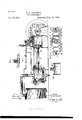
- FIG. 2 is a section along a; cc, Fig. I.
- Fig. 3 is a section along 'y y, Fig. l.
- Fig. 4 is a section along z e', Fig. l.
- the letter A' indicates a cylinder, in which a piston B moves back and forth, and C is the slide-valve, alternately admitting steam ythrough the ports D D into the cylinder.
- the steam is supplied through pipe E and chamber F and openings or mouths G G to the ports D.
- the piston-rod H actuates a piston I in cylinder K, so as to pump or force air from said cylinder into receiver L.
- the cylinder K is made to communicate with receiver L by means of a pipe M, which pipe communicates with a channel N, whose mouths O lead into cylinder K.
- the valves P alternately open and close these mouths, so as to open and close the communication with the receiver.
- the valves P are located in housings 0r channels Q, which by means of passages R communicate with the receiver.
- the right-hand valveP is open, so that the piston I can force air through channel N and pipe M into receiver L, while the left-hand valve P is closed, being held irmly shut by the pressure of air in receiver L, which by means of channel R can press on the back S of valve P.
- These backs or rear portions S of the valves are enlarged, so that they present sufficient surface for the compressed air to efficiently act on in forcing the valves shut.
- a spring can be employed to aid in closing each of the valves.
- the air enters cylinder K through the inlets T T, which communicate with the inlet-pipe U.
- valve Vis thus oscillated or actuated at the proper moments by the air-pressure at one end or the other of cylinder K.
- From the receiver L extends a tube Y into the upper part of chamber F.
- the valve Z in said upper part of chamber Fis held raised bythe steam-pressurein said chamber; but when the pressure of air in receiver yL becomes excessive said valve Z is forced down by the pressure in tube Y against the pressure of the steam and uncovers the opening or mouth of tube a, leading into the case or housingb of piston c, tofwhich is connected the valve or stopper cZ byarod c.
- the channel ol is also uncovered or opened, so that the compressed air travels along channelfi and pipe 7c and enters between the valves or stoppers Z Z and forces said Stoppers apart, so as to close or partially close the openings G, leading from chamber F to the passage in valve C.
- the Stoppers Z are slidably mounted on reciprocating rod m, so that said Stoppers will not abruptly close the access of steam to valve C, but the steam is allowed to Iiow to piston B during only a part of the stroke of the latter, so that the piston B is not subjected IOO throughout its ent-ire stroke to the full pressure of steam from the boiler, but such steam.
- Alug n prevents the Stoppers from coming together, thus leaving space between the stoppers, into which space the air from tube lo can enter to spread or separate the Stoppers.
- rod fm can be provided with lugs to prevent the Stoppers from spreading too far.
- the rod fm, as also the rod p, which oscillates the valve C, are actuated by suitable arms or levers q, linked to eccentrics fr on shaft s, which isv rotated by a cranlepin t andi pitman u, receiving motion from piston-rod
- the tube Y is shown provided with a valve v, pressed to its seat by a spring'w, and when the pressure of air in the receiverl.. andi tube Y becomes excessive said valve u is forced from its seat, and ⁇ the compressed air can then pass to thevalve-Z.
- the springw is secured at its upper end to a stem: fr, and by setting the stem m higher or lower byihe setting-nut y and jam-nut z the pressureofv the spring on valve fu isv regulated.
- the valve o slides on the stem
- the plate A is located atL theback of valve 0,50 as to keep the pressure of steam olf the back of said valve, thus enabling the valve to work easily on its seat.
Landscapes
- Engineering & Computer Science (AREA)
- Mechanical Engineering (AREA)
- General Engineering & Computer Science (AREA)
- Reciprocating Pumps (AREA)
Description
(No Model.)
T. F. PARRBLL.
AIR COMPRESSOR.
Patented July 19, 1892.
ATTORNEYS WITNESS/5S,
www
TME ums Perzns co.. moro-uma., wnsnwamn, n. c.
UNITED STATES PATENT OFFICE.
THOMAS F. FARRELL, OF PATERSON, NEW JERSEY.
AIR-COMPRESSOR.
SPECIFICATION forming part of Letters Patent No. 479,260, dated July 19, 1892.
Application iiled July 9, 1891. Serial No. 398,944. (No model.)
To a/ZZ whom t ymay concern.-
Beit known that I, THOMAS F. FARRELL, a citizen of the United States, residing at Paterson, in the county of Passaic and State of New Jersey, have invented new and useful Improvements in Air-Compressors, of which the following is-a specification.
This invention relates to an improvement in air-compressors; and the invention consists in the details of construction set forth in the following specification and claims, and illustrated in the annexed drawings, in which- Figure l isa sectional side elevation of the compressor. Fig. 2 is a section along a; cc, Fig. I. Fig. 3 is a section along 'y y, Fig. l. Fig. 4 is a section along z e', Fig. l.
In the drawings, the letter A' indicates a cylinder, in which a piston B moves back and forth, and C is the slide-valve, alternately admitting steam ythrough the ports D D into the cylinder. The steam is supplied through pipe E and chamber F and openings or mouths G G to the ports D.
The piston-rod H actuates a piston I in cylinder K, so as to pump or force air from said cylinder into receiver L. The cylinder K is made to communicate with receiver L by means of a pipe M, which pipe communicates with a channel N, whose mouths O lead into cylinder K. The valves P alternately open and close these mouths, so as to open and close the communication with the receiver. The valves P are located in housings 0r channels Q, which by means of passages R communicate with the receiver. When the piston I moves in the direction of arrow 1, Fig. l, the right-hand valveP is open, so that the piston I can force air through channel N and pipe M into receiver L, while the left-hand valve P is closed, being held irmly shut by the pressure of air in receiver L, which by means of channel R can press on the back S of valve P. These backs or rear portions S of the valves are enlarged, so that they present sufficient surface for the compressed air to efficiently act on in forcing the valves shut. A spring can be employed to aid in closing each of the valves. The air enters cylinder K through the inlets T T, which communicate with the inlet-pipe U. When the piston I travels in the direction of arrow l, the air enters the cylinder K through the inlet T at the left, the valve V being in position to close the other inlet T. This valve moves in housings W, communicating by channels X with the interior'of cylinder K. When the piston I moves in the direction of arrow l, the air entering the channel X at the right, as indicated by arrow 3, will hold the valve in the position shown in Fig. l,while if the piston I moves in the opposite direction the air entering through the other channel X will force the valve V to the right, so as to close the inlet T at the left and open the inlet at the right. The valve Vis thus oscillated or actuated at the proper moments by the air-pressure at one end or the other of cylinder K. From the receiver L extends a tube Y into the upper part of chamber F. The valve Z in said upper part of chamber Fis held raised bythe steam-pressurein said chamber; but when the pressure of air in receiver yL becomes excessive said valve Z is forced down by the pressure in tube Y against the pressure of the steam and uncovers the opening or mouth of tube a, leading into the case or housingb of piston c, tofwhich is connected the valve or stopper cZ byarod c. The pressure of the air from tube a forces the piston c against the pressure of spring f and draws the stopper CZ out of the channel g, whose mouths h enter the cylinder K near opposite ends of the latter. Vhen the stopper CZ is drawn out of channel g, the reciprocations of the piston I will merely cause the air to swing or move back and forth through the unobstructed channel g; but the pumping operation is stopped, as no more air is now forced past valves P into tube M and receiver L. When the air in tube Y forces the valve Z down, the channel ol is also uncovered or opened, so that the compressed air travels along channelfi and pipe 7c and enters between the valves or stoppers Z Z and forces said Stoppers apart, so as to close or partially close the openings G, leading from chamber F to the passage in valve C. The Stoppers Z are slidably mounted on reciprocating rod m, so that said Stoppers will not abruptly close the access of steam to valve C, but the steam is allowed to Iiow to piston B during only a part of the stroke of the latter, so that the piston B is not subjected IOO throughout its ent-ire stroke to the full pressure of steam from the boiler, but such steam.
from the boiler is admitted to the piston du ring only a part of its stroke, after which the steam is cut oft' and the expansive force of the steam which has been admitted to the piston causes the piston to complete its stroke. Alug n prevents the Stoppers from coming together, thus leaving space between the stoppers, into which space the air from tube lo can enter to spread or separate the Stoppers. rod fm can be provided with lugs to prevent the Stoppers from spreading too far. The rod fm, as also the rod p, which oscillates the valve C, are actuated by suitable arms or levers q, linked to eccentrics fr on shaft s, which isv rotated by a cranlepin t andi pitman u, receiving motion from piston-rod The tube Y is shown provided with a valve v, pressed to its seat by a spring'w, and when the pressure of air in the receiverl.. andi tube Y becomes excessive said valve u is forced from its seat, and` the compressed air can then pass to thevalve-Z. The springw is secured at its upper end to a stem: fr, and by setting the stem m higher or lower byihe setting-nut y and jam-nut z the pressureofv the spring on valve fu isv regulated. The valve o slides on the stem The plate A is located atL theback of valve 0,50 as to keep the pressure of steam olf the back of said valve, thus enabling the valve to work easily on its seat.
What I claim asy new, and desire to secure by Letters Patent, is
1. The combination, with a receiver and a cylinder K, having a housing b, of a valvechamber F, a pipe Y, leading from the receiver to the valve-chamber, a pipe a, leading from :stopper or valve being actuated bythe pressure in the pipe a, substantially as described. 2. The combination, with a receiver, of a cylinder made to communicate with said re- (zeivei,` said cylinder beingprovided with a 'piston I and with a channel having mouths h, leading into the cylinder at opposite sides of the piston, a stopper or valve d forA said channel, an actuating-piston B, a cylinder A for said actuatingpistom Stoppers or valvesl for intercepting the steam-supply to said cylinder, a supply-pipeY, and pipes or channels 'L' forconveying pressuret'rom the receiver `to the valves d l, respectively, for actuatingr the latter, said supply-pipe being provided with a valve and a spring or weight for holdis attained and said pipe Y being made to communicate with the pipes or channels a t',
ing said valve closed until a certain pressure leading, respectively, to the valves d Z, and a valve Z, actuated bythe pressure in the pipe Y for openingthe pipes or channels a e', sub stantialliy as described.
In testimony whereof I have hereunto set my hand in the presence of two subscribing witnesses.
T. F. FARRELL.
Witnesses:
WM. C. HAUFF, E. F. KASTENHUBER.
Publications (1)
| Publication Number | Publication Date |
|---|---|
| US479260A true US479260A (en) | 1892-07-19 |
Family
ID=2548114
Family Applications (1)
| Application Number | Title | Priority Date | Filing Date |
|---|---|---|---|
| US479260D Expired - Lifetime US479260A (en) | Air-compressor |
Country Status (1)
| Country | Link |
|---|---|
| US (1) | US479260A (en) |
Cited By (2)
| Publication number | Priority date | Publication date | Assignee | Title |
|---|---|---|---|---|
| US20080245569A1 (en) * | 2006-12-28 | 2008-10-09 | Schlumberger Technology Corporation | Apparatus and Methods to Perform Focused Sampling of Reservoir Fluid |
| US20230358219A1 (en) * | 2017-08-03 | 2023-11-09 | Insulet Corporation | Micro piston pump |
-
0
- US US479260D patent/US479260A/en not_active Expired - Lifetime
Cited By (4)
| Publication number | Priority date | Publication date | Assignee | Title |
|---|---|---|---|---|
| US20080245569A1 (en) * | 2006-12-28 | 2008-10-09 | Schlumberger Technology Corporation | Apparatus and Methods to Perform Focused Sampling of Reservoir Fluid |
| US7878244B2 (en) * | 2006-12-28 | 2011-02-01 | Schlumberger Technology Corporation | Apparatus and methods to perform focused sampling of reservoir fluid |
| US20230358219A1 (en) * | 2017-08-03 | 2023-11-09 | Insulet Corporation | Micro piston pump |
| US12320341B2 (en) * | 2017-08-03 | 2025-06-03 | Insulet Corporation | Micro piston pump |
Similar Documents
| Publication | Publication Date | Title |
|---|---|---|
| US233432A (en) | Air-compressor | |
| US479260A (en) | Air-compressor | |
| US640488A (en) | Must-pump. | |
| US648820A (en) | Valve-gear for engines. | |
| US255222A (en) | Air-compressor | |
| US679955A (en) | Valve mechanism for engines for compressing air or gases. | |
| US533817A (en) | Automatic hydraulic air-pump | |
| US1046167A (en) | Pump. | |
| US302206A (en) | krutzsch | |
| US641896A (en) | Valve-operating device for compressors. | |
| US381876A (en) | Compressing or blowing engine | |
| US508495A (en) | William c | |
| US756993A (en) | Valve mechanism for pumps. | |
| US738920A (en) | Air-compressor. | |
| US867774A (en) | Valve for direct-acting steam-pumps. | |
| US1260816A (en) | Reciprocating engine. | |
| US711939A (en) | Valve mechanism for compressors. | |
| US347874A (en) | Steam-engine | |
| US460617A (en) | Direct-acting engine | |
| US475776A (en) | Hydraulic motor for organs | |
| US850248A (en) | Pump. | |
| US912486A (en) | Blowing-engine. | |
| US123185A (en) | Improvement in steam-pumps | |
| US112151A (en) | Improvement in steam and water engines | |
| US624700A (en) | Steam-engine |