EP4372292A1 - Klimaanlage - Google Patents
Klimaanlage Download PDFInfo
- Publication number
- EP4372292A1 EP4372292A1 EP22840975.1A EP22840975A EP4372292A1 EP 4372292 A1 EP4372292 A1 EP 4372292A1 EP 22840975 A EP22840975 A EP 22840975A EP 4372292 A1 EP4372292 A1 EP 4372292A1
- Authority
- EP
- European Patent Office
- Prior art keywords
- controller
- operating
- air conditioner
- end plate
- operating surface
- Prior art date
- Legal status (The legal status is an assumption and is not a legal conclusion. Google has not performed a legal analysis and makes no representation as to the accuracy of the status listed.)
- Granted
Links
Images

Classifications
-
- F—MECHANICAL ENGINEERING; LIGHTING; HEATING; WEAPONS; BLASTING
- F24—HEATING; RANGES; VENTILATING
- F24F—AIR-CONDITIONING; AIR-HUMIDIFICATION; VENTILATION; USE OF AIR CURRENTS FOR SCREENING
- F24F13/00—Details common to, or for air-conditioning, air-humidification, ventilation or use of air currents for screening
- F24F13/20—Casings or covers
- F24F2013/207—Casings or covers with control knobs; Mounting controlling members or control units therein
Definitions
- the present disclosure relates to the field of air conditioner manufacturing, and more particularly to an air conditioner.
- Air conditioners mainly function to adjust the temperature, which can be applied to different life scenarios with different heat exchangers.
- the further refinement of air conditioning products will have higher requirements for product function requirements and after-sales maintenance.
- Centralized heating integrated water heaters and a swimming pool machines in related art integrate an indoor unit and an outdoor unit of the original air conditioners into one, making the installation and use of the product more convenient.
- a controller of such products is mainly divided into two types.
- One is an external controller which, that is, the controller can be separated from the air conditioner body, and mounted to an indoor wall or an outdoor wall, etc.; the other is a built-in controller, that is, the controller is arranged on the air conditioner, and mostly arranged on a front panel or a right rear panel of the air conditioner, when disassembling, it is necessary to disassemble the peripheral sheet metal of the air conditioner, thus the operation is inconvenient, and the arrangment of the controller is also not flexible enough.
- the present disclosure aims to solve at least one of the technical problems existing in the related art to at least some extent. Therefore, the present disclosure proposes an air conditioner with high space utilization.
- the air conditioner includes a body, the body comprising a housing, the housing comprising a protruding portion protruding outwards, the protruding portion defining an accommodating cavity; and a controller, at least a part of the controller being located in the accommodating cavity, the protruding portion being provided with an operating hole communicated with the accommodating cavity, an operating surface of the controller being opposite to the operating hole so that the operating surface is exposed, or the operating surface of the controller being arranged on an outer side surface of the protruding portion.
- the controller is arranged in an accommodating cavity formed by the protruding portion of the housing, the accommodating cavity may be utilized without affecting the original appearance of the housing of the air conditioner, thus improving the space utilization inside the air conditioner.
- the air conditioner provided by embodiments of the present disclosure has the advantage of high space utilization.
- the housing includes a housing body and a handle casing
- the handle casing is detachably arranged on the housing body
- the handle casing constitutes the protruding portion
- the handle casing includes an end plate and a surrounding plate surrounding the end plate
- the operating hole is defined in the end plate
- the controller is detachably connected with the handle casing, or the operating surface is arranged on the end plate and integrated with the end plate.
- a part of the end plate is recessed inwards relative to another part of the end plate to form a handle slot.
- the controller includes an operating panel, the operating panel has the operation surface, at least a part of the operating panel is fitted in the operating hole, a remaining part of the controller is located at a rear side of the operating panel and is located in the accommodating cavity, and the remaining part of the controller abuts against a part of the end plate located near the operating hole, so that the controller is limited in a forward direction.
- the air conditioner includes a controller support member, the controller support member is connected to a rear wall surface of the end plate and surrounds the remaining part of the controller, and the remaining part of the controller is fitted into the controller support member, so that the controller is limited and supposed in up, down, left and right directions.
- the controller support member is also connected with a limiting part abutting against the controller in the front-and-rear direction so that the controller is limited in a backward direction
- the air conditioner further includes a controller limiting member, the controller limiting member is connected with the controller support member or is connected with the rear wall surface of the end plate, and the controller limiting member includes a part abutting against the controller in the front-and-rear direction, so that the controller is limited in the backward direction.
- the air conditioner further includes a sealing ring, the sealing ring is fitted in the operating hole and located between the operating panel and the end plate.
- the operating hole is defined in the end plate
- the air conditioner includes a controller mounting box
- the controller mounting box defines a mounting cavity
- a front side of the mounting cavity is open
- the controller is mounted in the mounting cavity
- the operating surface is opposite to a front side opening of the mounting cavity so that the operating surface is exposed
- at least a part of the controller mounting box is located in the accommodating cavity and connected to the end plate.
- the air conditioner includes a cover plate, the cover plate is connected to the controller mounting box in a rotatable manner between a covering position of covering the operating surface and an exposing position of exposing the operating surface.
- the air conditioner includes a cover plate, the cover plate is connected to the handle casing in a rotatable manner between a covering position of covering the operating surface and an exposing position of exposing the operating surface.
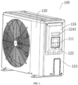
- controller 110 operating surface 111; housing 120; accommodating cavity 121; operating hole 122; housing body 123; handle casing 124; end plate 1241; surrounding plate 1242; handle slot 1243; controller support member 130; controller limiting member 140; sealing ring 150; cover plate 160; controller mounting box 170.
- the air conditioner 100 of embodiments of the present disclosure is described below according to FIGS. 1-3 .
- the air conditioner 100 includes a body and a controller 110.
- the body includes a housing 120.
- the housing 120 includes a protruding portion protruding outwards, and the protruding portion defines an accommodating cavity 121.
- At least a part of the controller 110 is located in the accommodating cavity 121, that is, at least part of the controller 110 is located in the accommodating cavity 121 formed by the protruding portion on the housing 120 protruding outwards, and the accommodating cavity 121 is located at a rear space of the protruding portion.
- the protruding portion is provided with an operating hole 122 communicated with the accommodating cavity 121, an operating surface 111 of the controller 110 is opposite to the operating hole 122, and the operating surface 111 is exposed through the operating surface 111. Since the operating surface 111 is exposed through the operating surface 111, an operator may perform a touch operation on the operating surface 111 of the controller 110. Alternatively, the operating surface 111 of the controller 110 is arranged on an outer side surface of the protruding portion, and the operator may also perform the touch operation through the operating surface 111 on the outer side surface of the protruding portion.
- the controller is arranged in an accommodating cavity formed by the protruding portion of the housing, and the accommodating cavity may be utilized without affecting the original appearance of the housing of the air conditioner, thus improving the space utilization inside the air conditioner.
- the air conditioner provided by embodiments of the present disclosure has the advantage of high space utilization.
- the housing 120 includes a housing body 123 and a handle casing 124, the handle casing 124 is detachably arranged on the housing body 123, and the handle casing 124 constitutes the protruding portion of the housing 120. Further, the handle casing 124 includes an end plate 1241 and a surrounding plate 1242 surrounding and connected to the end plate 1241.
- the controller 110 is detachably connected with the handle casing 124, the end plate 1241 is provided with an operating hole 122 communicated with the accommodating cavity 121, the operating surface 111 of the controller 110 is opposite to the operating hole 122, and the operating surface 111 is exposed through the operating surface 111.
- the operator may perform a touch operation on the operating surface 111 exposed through operation hole 122, and at this time, the controller 110 is built-in. Since the controller 110 is detachably connected to the handle casing 124, the controller 110 may be removed from the handle casing 124 and placed on an indoor wall or an outdoor wall, and in this time, the controller 110 is external.
- the handle casing 124 When removing the controller 110, the handle casing 124 may be removed from the housing body 123 first, and then the controller 110 connected to the handle casing 124 may be removed, without disassembling the peripheral sheet metal of the housing body 123 or the housing 120, which is convenient and quick, convenient for after-sales maintenance, and makes the arrangement of the controller 110 more flexible.
- the end plate 1241 is not provided with the operating hole 122, and the operating surface 111 of the controller 110 is arranged on the end plate 1241 and integrated with the end plate 1241.
- the outer side surface of the end plate 1241 is the outer side surface of the protruding portion.
- the handle casing 124 is integrated with the operating surface 111 of the controller 110.
- the operating surface 111 is a touch-sensitive operating board, for example, the handle casing 124 is made of plastic, and the controller 110 may be controlled by touching the operating surface 111 arranged on the end plate 1241.
- FIGS. 1-3 Several embodiments provided by the present embodiment are described in detail below according to FIGS. 1-3 .
- an air conditioner 100 includes a body and a controller 110.
- the body includes a housing 120
- the housing 120 includes a housing body 123 and a handle casing 124 detachably arranged on the housing body 123.
- the handle casing 124 protrudes outwards with respect to the housing body 123 to form a protruding portion.
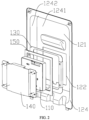
- the handle casing 124 includes an end plate 1241 and a surrounding plate 1242, and the end plate 1241 and the surrounding plate 1242 define an accommodating cavity 121 located on a rear side of the end plate 1241. A part of the end plate 1241 is recessed towards an interior of the accommodating cavity 121 relative to a remaining part to form a handle slot 1243, and the handle slot 1243 is convenient for an operator to handle the air conditioner 100.
- the controller 110 is placed inside just by utilizing the accommodating cavity 121 defined by the handle casing 124 of the air conditioner 100, which does not change the original appearance of the air conditioner 100, and improves the space utilization. It should be noted that the present embodiment only takes the handle casing 124 as an example. In other embodiments, the controller 110 may also be placed in an accommodating cavity 121 defined by the other protruding portions formed on the housing 120 of the air conditioner 100, which may also improve the space utilization and not elaborated herein.
- an operating hole 122 is defined in the end plate 1241 for exposing the operating surface 111 of the controller 110.
- the controller 110 is detachably connected to the handle casing 124.
- the operating surface 111 is located in the operating hole 122, that is, the operating surface 111 is located between a front wall surface and a rear wall surface of the end plate 1241 in the front-and-rear direction, or the operating surface 111 is flush with the front wall surface of the end plate 1241, which is not limited herein.
- the controller 110 includes an operating panel, and the operation surface 111 is arranged on the front side surface of the operating panel.
- the remaining part of the controller 120 is located at a rear side of the operating panel. At least a part of the operating panel is fitted in the operating hole 122, and the remaining part of the controller 120 is located in the accommodating cavity 121.
- the remaining part of the controller 120 abuts against the rear wall surface of the end plate 1241, and more specifically, the remaining part of the controller 120 abuts the part of the end plate 1241 located near the operating hole 122, so that the controller 110 is limited in the forward direction.
- the control panel of the controller 110 is mounted into the operating hole 122 of the handle casing 124 from rear to front.
- the above arrangement enables the controller 110 to be limited during the mounting from rear to front, so that the controller 110 will not move forward out of the operation hole 122.
- the size of the remaining part of the controller 110 is larger than the size of the operating panel part, thereby forming a step structure on the controller 110.
- the air conditioner 100 of the present embodiment also includes a controller support member 130 and a controller limiting member 140.
- the controller support member 130 is configured to support the controller 110.
- the controller support member 130 is connected to the rear wall surface of the end plate 1241 and surrounds the remaining part of the controller 110 located in the accommodating cavity 121.
- the remaining part of the controller 110 is fitted into the controller support member 130, so that the controller support member 130 limits and supports the controller 110 in up, down, left and right directions.
- the controller support member 130 is a hollow frame, and the controller 110 passes through a middle through hole of the controller support member 130 from rear to front, so that the controller support member 130 is sleeved on the remaining part of the controller 110.
- the controller 110 will not jump or move in the up, down, left and right directions.
- the controller limiting member 140 is mounted on the rear wall surface of the end plate 1241 from the rear, the controller limiting member 140 includes a part that abuts against the controller 110 in the front-and-rear direction, and the part abuts against the rear side of the controller 110 to limit the controller 110 in the backward direction. That is, the controller limiting member 140 is connected to the rear wall surface of the end plate 1241, and the controller limiting member 140 is configured to limit the controller 110 in the backward direction.
- the controller limiting member 140 may also be connected to the controller support member 130.
- the air conditioner 100 may also exclude the controller limiting member 140, so that the controller support member 130 is connected with a limiting part, and the limiting part abuts against the controller 110 in the front-and-rear direction, which may also realize limit on the controller 110 in the backward direction. That is, the controller support member 130 is configured to limit the controller 110 in the up, down, left and right directions and backward direction simultaneously.
- the air conditioner 100 also includes a sealing ring 150.
- the sealing ring 150 is fitted in the operating hole 122 and located between the part of the operating panel fitted in the operating hole 122 and the end plate 1241.
- an outer peripheral surface of the seal ring 150 abuts against a peripheral surface of the operating hole 122
- an inner peripheral surface of the seal ring 150 abuts against a part of the operating panel located in the operating hole 122
- the seal ring 150 is used for sealing between the controller 110 and the end plate 1241, to prevent water or dust from entering the interior of the air conditioner 100 through the gap between the controller 110 and the end plate 1241 to affect the operation of the air conditioner 100.
- the air conditioner 100 further includes a cover plate 160.
- the cover plate 160 is connected to a handle casing 124 in a rotatable manner between a covering position of covering the operating surface 111 and an exposing position of exposing the operating surface 111.
- the cover plate 160 may be connected to the end plate 1241, and a connection position with the end plate 1241 may be located above the operating hole 122.
- controller 110 does not need to be operated, the cover plate 160 may be rotated to the covering position of covering the operating surface 111 to prevent water and dust.
- the cover plate 160 may be rotated to the exposing position of exposing the operating surface 111, to facilitate the operation of the operating surface 111.
- the cover plate 160 may be moved to the covering position of covering the operating surface 111, to prevent water or dust from entering the interior of the air conditioner through the operating hole 122.
- the air conditioner 100 includes a body and a controller 110.
- the body includes a housing 120
- the housing 120 includes a housing body 123 and a handle casing 124 detachably arranged on the housing body 123.
- the handle casing 124 protrudes outwards with respect to the housing body 123 to form the protruding portion.
- the handle casing 124 includes an end plate 1241 and a surrounding plate 1242, and the end plate 1241 and the surrounding plate 1242 define an accommodating cavity 121 located on the rear side of the end plate 1241.
- a part of the end plate 1241 is recessed towards the interior of the accommodating cavity 121 relative to the remaining part of the end plate 1241 to form a handle slot 1243, and the handle slot 1243 is convenient for the operator to handle the air conditioner 100.
- the operating hole 122 is defined in the end plate 1241.
- the controller 110 is detachably connected to the handle casing 124.
- the air conditioner 100 includes a controller mounting box 170.
- the controller mounting box 170 defines a mounting cavity, and a front side of the mounting cavity is open.
- the controller 110 is mounted in the mounting cavity of the controller mounting box 170, the operating surface 111 is opposite to a front side opening of the mounting cavity so that the operating surface 111 is exposed, and at least a part of the controller mounting box 170 is located in the accommodating cavity 121 and connected to the end plate 1241. It is understood that, in order to expose the operating surface 111, the front side opening of the mounting cavity is opposite to the operating hole 122.
- the handle casing 124 may be first mounted on the housing body 123, the controller 110 may be mounted in the mounting cavity of the controller mounting box 170, the controller mounting box 170 mounted with the controller 110 passes through the operating hole 122 from front to rear, and the controller mounting box 170 may be mounted into the accommodating cavity 121.
- the controller mounting box 170 mounted with the controller 110 may be mounted on the end plate 1241 from rear to front, and then the handle casing 124 may be connected to the housing body 123. Adopting the first mounting method, when the controller 110 needs to be disassembled, the controller mounting box 170 may be directly removed from the handle casing 124 without disassembling the handle casing 124, which is more convenient and quicker.
- the air conditioner 100 further includes a cover plate 170, and the cover plate 160 is connected to the controller mounting box 170 in a rotatable manner between a covering position of covering the operating surface 111 and an exposing position of exposing the operating surface 111.
- the cover plate 160 may be rotated to the covering position of covering the operating surface 111 to prevent water and dust.
- the cover plate 160 may be rotated to the exposing position of exposing the operating surface 111 to facilitate operation on the operating surface 111.
- the cover plate 160 may also be connected to the handle casing 124 in a rotatable manner between the covering position of covering the operating surface 111 and the exposing position of exposing the operating surface 111.
- first and second are only used for purpose of description, and cannot be understood as indicating or implying relative importance or implicitly indicating the number of indicated technical features. Therefore, the feature defined as “first” or “second” may explicitly or implicitly include at least one such feature. In the description of the present disclosure, "a plurality of” means at least two, such as two, three, etc., unless otherwise specifically defined.
- mount shall be understood broadly, and may be, for example, fixed connections, detachable connections, or integral connections; may also be mechanical or electrical connections or intercommunication; may also be direct connections or indirect connections via intervening media; may also be inner communications or interactions of two elements, unless otherwise specifically defined.
- mount shall be understood broadly, and may be, for example, fixed connections, detachable connections, or integral connections; may also be mechanical or electrical connections or intercommunication; may also be direct connections or indirect connections via intervening media; may also be inner communications or interactions of two elements, unless otherwise specifically defined.
- mount shall be understood broadly, and may be, for example, fixed connections, detachable connections, or integral connections; may also be mechanical or electrical connections or intercommunication; may also be direct connections or indirect connections via intervening media; may also be inner communications or interactions of two elements, unless otherwise specifically defined.
- a structure in which a first feature is "on" or “below” a second feature may include an embodiment in which the first feature is in direct contact with the second feature, or may further include an embodiment in which the first feature and the second feature are in indirect contact through intermediate media.
- a first feature "on”, “above”, or “on top of” a second feature may include an embodiment in which the first feature is right or obliquely “on”, “above”, or “on top of” the second feature, or just means that the first feature is at a height higher than that of the second feature
- a first feature "below”, “under”, or “on bottom of” a second feature may include an embodiment in which the first feature is right or obliquely “below”, “under”, or “on bottom of” the second feature, or just means that the first feature is at a height lower than that of the second feature.
Landscapes
- Engineering & Computer Science (AREA)
- Chemical & Material Sciences (AREA)
- Combustion & Propulsion (AREA)
- Mechanical Engineering (AREA)
- General Engineering & Computer Science (AREA)
- Air Filters, Heat-Exchange Apparatuses, And Housings Of Air-Conditioning Units (AREA)
Applications Claiming Priority (2)
| Application Number | Priority Date | Filing Date | Title |
|---|---|---|---|
| CN202121632827.6U CN216132086U (zh) | 2021-07-16 | 2021-07-16 | 空调器 |
| PCT/CN2022/082605 WO2023284331A1 (zh) | 2021-07-16 | 2022-03-23 | 空调器 |
Publications (3)
| Publication Number | Publication Date |
|---|---|
| EP4372292A1 true EP4372292A1 (de) | 2024-05-22 |
| EP4372292A4 EP4372292A4 (de) | 2024-10-30 |
| EP4372292B1 EP4372292B1 (de) | 2025-10-22 |
Family
ID=80767753
Family Applications (1)
| Application Number | Title | Priority Date | Filing Date |
|---|---|---|---|
| EP22840975.1A Active EP4372292B1 (de) | 2021-07-16 | 2022-03-23 | Klimaanlage |
Country Status (4)
| Country | Link |
|---|---|
| US (1) | US20240393004A1 (de) |
| EP (1) | EP4372292B1 (de) |
| CN (1) | CN216132086U (de) |
| WO (1) | WO2023284331A1 (de) |
Families Citing this family (1)
| Publication number | Priority date | Publication date | Assignee | Title |
|---|---|---|---|---|
| WO2025148938A1 (zh) * | 2024-01-09 | 2025-07-17 | 广东美的暖通设备有限公司 | 面板结构、室内机以及暖通系统 |
Family Cites Families (10)
| Publication number | Priority date | Publication date | Assignee | Title |
|---|---|---|---|---|
| US6009717A (en) * | 1998-08-26 | 2000-01-04 | Carrier Corporation | Control box for a room air conditioner |
| JP4435823B2 (ja) * | 2007-11-09 | 2010-03-24 | シャープ株式会社 | 開口カバー装置及びそれを備えた空気調和機 |
| CN203375540U (zh) * | 2013-06-26 | 2014-01-01 | 广州华凌制冷设备有限公司 | 空调器室内机 |
| KR20180065725A (ko) * | 2016-12-08 | 2018-06-18 | 엘지전자 주식회사 | 공기 조화기의 실외기 |
| JP6628904B2 (ja) * | 2016-12-16 | 2020-01-15 | 三菱電機株式会社 | 空気調和機の室外機 |
| CN108209226A (zh) * | 2018-03-07 | 2018-06-29 | 佛山市顺德区美的洗涤电器制造有限公司 | 家用电器的控制面板安装结构和组合式厨房电器 |
| WO2020017021A1 (ja) * | 2018-07-20 | 2020-01-23 | 三菱電機株式会社 | ヒートポンプ給湯室外機 |
| CN209181118U (zh) * | 2018-11-27 | 2019-07-30 | 广东美的制冷设备有限公司 | 空调室内机及空调器 |
| CN109539392B (zh) * | 2018-12-29 | 2024-08-16 | 奥克斯空调股份有限公司 | 一种空调器 |
| CN212499789U (zh) * | 2020-07-10 | 2021-02-09 | 河北顶控新能源科技有限公司 | 一种驻车空调结构 |
-
2021
- 2021-07-16 CN CN202121632827.6U patent/CN216132086U/zh active Active
-
2022
- 2022-03-23 EP EP22840975.1A patent/EP4372292B1/de active Active
- 2022-03-23 WO PCT/CN2022/082605 patent/WO2023284331A1/zh not_active Ceased
- 2022-03-23 US US18/564,012 patent/US20240393004A1/en active Pending
Also Published As
| Publication number | Publication date |
|---|---|
| EP4372292B1 (de) | 2025-10-22 |
| EP4372292A4 (de) | 2024-10-30 |
| US20240393004A1 (en) | 2024-11-28 |
| CN216132086U (zh) | 2022-03-25 |
| WO2023284331A1 (zh) | 2023-01-19 |
Similar Documents
| Publication | Publication Date | Title |
|---|---|---|
| CN103307716A (zh) | 一种空调室内机电机安装结构及安装方法 | |
| EP4372292A1 (de) | Klimaanlage | |
| JP2017044411A (ja) | 空気調和機 | |
| CN108626783B (zh) | 用于空调室内机的导风板组件、空调室内机及空调器 | |
| US10012397B2 (en) | Indoor unit | |
| JP6919157B2 (ja) | 空気調和機の室内機 | |
| CN111936797B (zh) | 顶棚嵌入式空调机 | |
| WO2022217893A1 (zh) | 立式空调及立式空调风道结构的加工系统 | |
| CN112984628B (zh) | 一种出风组件及空调器 | |
| CN111380199B (zh) | 导风组件和空气处理装置 | |
| CN204786781U (zh) | 具有喇叭的空调室内机 | |
| CN220601627U (zh) | 一种风管机 | |
| JP2016130038A (ja) | レジスタ用操作ノブ | |
| JP2018098560A (ja) | リモートコントローラ | |
| JP2010071521A (ja) | 空気調和装置 | |
| CN214949421U (zh) | 移动空调器 | |
| CN205119374U (zh) | 传感器装置及空调器室内机 | |
| JP7630067B2 (ja) | 天井埋込型換気扇 | |
| CN214406245U (zh) | 空调器室内机 | |
| CN204176771U (zh) | 立式空调器 | |
| JP2014119126A (ja) | 床置形空気調和装置 | |
| CN216312838U (zh) | 用于车辆的驱动集成装置及车辆 | |
| CN220624191U (zh) | 一种空调器 | |
| CN223271353U (zh) | 空调器 | |
| CN223241649U (zh) | 轴流风扇及具有其的除湿机 |
Legal Events
| Date | Code | Title | Description |
|---|---|---|---|
| STAA | Information on the status of an ep patent application or granted ep patent |
Free format text: STATUS: THE INTERNATIONAL PUBLICATION HAS BEEN MADE |
|
| PUAI | Public reference made under article 153(3) epc to a published international application that has entered the european phase |
Free format text: ORIGINAL CODE: 0009012 |
|
| STAA | Information on the status of an ep patent application or granted ep patent |
Free format text: STATUS: REQUEST FOR EXAMINATION WAS MADE |
|
| 17P | Request for examination filed |
Effective date: 20231124 |
|
| AK | Designated contracting states |
Kind code of ref document: A1 Designated state(s): AL AT BE BG CH CY CZ DE DK EE ES FI FR GB GR HR HU IE IS IT LI LT LU LV MC MK MT NL NO PL PT RO RS SE SI SK SM TR |
|
| DAV | Request for validation of the european patent (deleted) | ||
| DAX | Request for extension of the european patent (deleted) | ||
| A4 | Supplementary search report drawn up and despatched |
Effective date: 20240927 |
|
| RIC1 | Information provided on ipc code assigned before grant |
Ipc: F24F 13/20 20060101AFI20240923BHEP |
|
| GRAP | Despatch of communication of intention to grant a patent |
Free format text: ORIGINAL CODE: EPIDOSNIGR1 |
|
| STAA | Information on the status of an ep patent application or granted ep patent |
Free format text: STATUS: GRANT OF PATENT IS INTENDED |
|
| INTG | Intention to grant announced |
Effective date: 20250804 |
|
| GRAS | Grant fee paid |
Free format text: ORIGINAL CODE: EPIDOSNIGR3 |
|
| GRAA | (expected) grant |
Free format text: ORIGINAL CODE: 0009210 |
|
| STAA | Information on the status of an ep patent application or granted ep patent |
Free format text: STATUS: THE PATENT HAS BEEN GRANTED |
|
| AK | Designated contracting states |
Kind code of ref document: B1 Designated state(s): AL AT BE BG CH CY CZ DE DK EE ES FI FR GB GR HR HU IE IS IT LI LT LU LV MC MK MT NL NO PL PT RO RS SE SI SK SM TR |
|
| REG | Reference to a national code |
Ref country code: CH Ref legal event code: F10 Free format text: ST27 STATUS EVENT CODE: U-0-0-F10-F00 (AS PROVIDED BY THE NATIONAL OFFICE) Effective date: 20251022 Ref country code: GB Ref legal event code: FG4D |
|
| REG | Reference to a national code |
Ref country code: DE Ref legal event code: R096 Ref document number: 602022023645 Country of ref document: DE |