EP4366263A1 - Kommunikationssystem, kommunikationsverfahren und programm - Google Patents
Kommunikationssystem, kommunikationsverfahren und programm Download PDFInfo
- Publication number
- EP4366263A1 EP4366263A1 EP21948244.5A EP21948244A EP4366263A1 EP 4366263 A1 EP4366263 A1 EP 4366263A1 EP 21948244 A EP21948244 A EP 21948244A EP 4366263 A1 EP4366263 A1 EP 4366263A1
- Authority
- EP
- European Patent Office
- Prior art keywords
- transmission device
- unit
- setting
- data
- transmission
- Prior art date
- Legal status (The legal status is an assumption and is not a legal conclusion. Google has not performed a legal analysis and makes no representation as to the accuracy of the status listed.)
- Granted
Links
Images










Classifications
-
- H—ELECTRICITY
- H04—ELECTRIC COMMUNICATION TECHNIQUE
- H04L—TRANSMISSION OF DIGITAL INFORMATION, e.g. TELEGRAPHIC COMMUNICATION
- H04L41/00—Arrangements for maintenance, administration or management of data switching networks, e.g. of packet switching networks
- H04L41/08—Configuration management of networks or network elements
- H04L41/0803—Configuration setting
- H04L41/0813—Configuration setting characterised by the conditions triggering a change of settings
- H04L41/0816—Configuration setting characterised by the conditions triggering a change of settings the condition being an adaptation, e.g. in response to network events
-
- H—ELECTRICITY
- H04—ELECTRIC COMMUNICATION TECHNIQUE
- H04B—TRANSMISSION
- H04B10/00—Transmission systems employing electromagnetic waves other than radio-waves, e.g. infrared, visible or ultraviolet light, or employing corpuscular radiation, e.g. quantum communication
- H04B10/27—Arrangements for networking
-
- H—ELECTRICITY
- H04—ELECTRIC COMMUNICATION TECHNIQUE
- H04L—TRANSMISSION OF DIGITAL INFORMATION, e.g. TELEGRAPHIC COMMUNICATION
- H04L12/00—Data switching networks
- H04L12/02—Details
- H04L12/12—Arrangements for remote connection or disconnection of substations or of equipment thereof
-
- H—ELECTRICITY
- H04—ELECTRIC COMMUNICATION TECHNIQUE
- H04L—TRANSMISSION OF DIGITAL INFORMATION, e.g. TELEGRAPHIC COMMUNICATION
- H04L41/00—Arrangements for maintenance, administration or management of data switching networks, e.g. of packet switching networks
- H04L41/40—Arrangements for maintenance, administration or management of data switching networks, e.g. of packet switching networks using virtualisation of network functions or resources, e.g. SDN or NFV entities
Definitions
- the present invention relates to a communication system, a communication method, and a program.
- Fig. 25 is a diagram illustrating a first example of a configuration of a communication system.
- a first transmission device, a second transmission device, and a third transmission device are connected to one another via data lines (optical transmission lines) that are connected directly or indirectly to a data network 501.
- These transmission devices are controlled by a control server via a control network 500.
- the control network 500 is a communication network different from the data network 501 for data communication.
- a control server 7 centrally manages information regarding networks.
- the customer control server manages only information regarding external aspects (such as customer information and contracted service information). Accordingly, the customer control server transmits a setting request to the control server 7.
- the control server 7 derives data on the basis of the setting request, and gives an instruction to a transmission device under its control. As the transmission device under the control executes the instruction, the data network 501 is reconstructed.
- Fig. 26 is a diagram illustrating a second example of a configuration of a communication system.
- a setting device installed in the office of the user accesses the customer control server via another network under another contract.
- the data network 501 is also reconstructed as in Fig. 25 .
- the setting device and the arithmetic device installed in the office of the user may be the same device.
- Non Patent Document 1 Hideki Kasahara and four others, “Network Infrastructure Technologies for Next Generation Networks", NTT Technical Journal, April 2007, pp. 38-43
- All of the control network, the data network, and the transmission devices form communication networks under the control of a communications company (a communications services company). Therefore, the communication path design and the communication path construction of these communication networks are conducted primarily by the communications company.
- the present invention aims to provide a communication system, a communication method, and a program for enabling a user to quickly use and change communication services.
- An embodiment of the present invention is a communication system that includes: a plurality of transmission devices; a setting server that receives an instruction to change data related to setting of a data network; and a control server that performs a control process related to the plurality of transmission devices and the data network on the basis of the data.
- the plurality of transmission devices includes a first transmission device, and a second transmission device capable of communicating with the setting server and the control server.
- a setting processing unit is provided to perform a process for constructing a customer control network between the first transmission device and the setting server by using the second transmission device as a relay device, when the first transmission device and the second transmission device are connected by an optical transmission line.
- the first transmission device includes: a connection processing unit that performs a process for constructing a control network between the first transmission device and the control server by using the second transmission device as a relay device, when the first transmission device and the second transmission device are connected by the optical transmission line; and a device control unit that performs a process for constructing the data network for the first transmission device by using the second transmission device as a relay device, when the first transmission device and the second transmission device are connected by the optical transmission line.
- An embodiment of the present invention is a communication method implemented by a communication system that includes: a plurality of transmission devices; a setting server that receives an instruction to change data related to setting of a data network; and a control server that performs a control process related to the plurality of transmission devices and the data network on a basis of the data.
- the plurality of transmission devices includes a first transmission device, and a second transmission device capable of communicating with the setting server and the control server.
- the communication method includes a setting processing step of performing a process for constructing a customer control network between the first transmission device and the setting server by using the second transmission device as a relay device, when the first transmission device and the second transmission device are connected by an optical transmission line.
- the first transmission device performs a process for constructing a control network between the first transmission device and the control server by using the second transmission device as a relay device when the first transmission device and the second transmission device are connected by the optical transmission line, and performs a process for constructing the data network for the first transmission device by using the second transmission device as a relay device when the first transmission device and the second transmission device are connected by the optical transmission line.
- An embodiment of the present invention is a program for causing a computer to function as the above communication system.
- a user can quickly use and change communication services.
- Fig. 1 is a diagram illustrating an example configuration of a communication system 1a.
- the communication system 1a includes a first transmission device 2a, a first arithmetic device 3, a second transmission device 4, a third transmission device 5, a fourth transmission device 6, a control server 7, a second arithmetic device 8, a customer control server 9, an optical transmission line 10, a control network 11, a data network 12, and a customer control network 13.
- the second transmission device 4, the third transmission device 5, the fourth transmission device 6, the control server 7, and the customer control server 9 are managed by the same communications company, for example.
- the first transmission device 2a may be prepared by a user, or may be prepared by the communications company.
- the first transmission device 2a includes a setting processing unit 20, a device control unit 21, a control communication unit 22, a connection processing unit 23, a setting change communication unit 24, a data communication unit 25, a multiplexing/demultiplexing unit 26, and an optical signal communication unit 27.
- the first arithmetic device 3 includes a first arithmetic unit 31 and a device connection unit 32.
- the device connection unit 32 is connected to an input/output device 30.
- the number of the input/output devices 30 may be plural.
- the first arithmetic device 3 may include at least one of the functional units (not illustrated) in the input/output device 30.
- the second transmission device 4 includes a device control unit 40, a control communication unit 41, a connection processing unit 42, a setting change communication unit 43, a data communication unit 44, a multiplexing/demultiplexing unit 45, and an optical signal communication unit 46.
- the third transmission device 5 includes a data communication unit 50, an optical signal communication unit 51, and a device control unit 52.
- the fourth transmission device 6 includes a device control unit 60, a data communication unit 61, and an optical signal communication unit 62.
- the second arithmetic device 8 includes a second arithmetic unit 81.
- An input/output device is at least one of a video output device such as a monitor, a keyboard, a mouse, and a sensor, for example.
- the first transmission device 2a, the first arithmetic device 3, and the input/output device 30 are provided in the user's facility, for example.
- the user's facility is an office 100 as an example.
- the setting processing unit 20 may be provided in the office 100 as a device separate from the first transmission device 2a.
- the second transmission device 4 and the third transmission device 5 are provided in a first station 200 (a relay station) of the communications company, for example.
- the fourth transmission device 6 and the second arithmetic device 8 are provided in a data center 300 of the communications company, for example.
- the first transmission device 2a is an optical network unit (ONU), for example.
- the first transmission device 2a is physically connected to the optical transmission line 10 by the user.
- the first transmission device 2a When connected to the optical transmission line 10, the first transmission device 2a temporarily constructs a connection line between the connection processing unit 23 and the connection processing unit 42 in the optical transmission line 10.
- the same optical fiber is used for transmission and reception, but different optical fibers may be used for transmission and reception.
- the first transmission device 2a When connected directly or indirectly to the control server 7 via the optical transmission line 10, the first transmission device 2a constructs three kinds of communication networks. For example, using the optical transmission line 10, the first transmission device 2a constructs a control line (the first kind) for the control network 11 between the control communication unit 22 and the control server 7, and between the control communication unit 41 and the control server 7. Using the optical transmission line 10, the first transmission device 2a constructs a data line (the second kind) for the data network 12 between the data communication unit 25 and the second arithmetic device 8, and between the data communication unit 44 and the second arithmetic device 8.
- a control line the first kind
- the first transmission device 2a constructs a data line (the second kind) for the data network 12 between the data communication unit 25 and the second arithmetic device 8 between the data communication unit 44 and the second arithmetic device 8.
- the first transmission device 2a constructs a setting change line (the third kind) for the customer control network 13 (a setting network) between the setting change communication unit 24 and the customer control server 9, and between the setting change communication unit 43 and the customer control server 9. In this manner, the first transmission device 2a constructs three kinds of communication networks, without the communications company being the operator.
- the data is not necessarily a specific type of data, but may be a setting value, or may be a command, for example.
- the first transmission device 2a transmits data sent from the first arithmetic device 3, to the second transmission device 4 with an optical signal.
- the first transmission device 2a transmits data sent from the second transmission device 4 with an optical signal, to the first arithmetic device 3 with an electrical signal, for example.
- the first arithmetic device 3 is an information processing device, and is a smartphone terminal, a tablet terminal, a laptop computer, or a desktop personal computer, for example.
- the first arithmetic device 3 is operated by the user.
- the first arithmetic device 3 transmits data (operation data) corresponding to an operation received by the input/output device 30 to the first transmission device 2a in the uplink direction.
- the first arithmetic device 3 acquires data transmitted in the downlink direction from the first transmission device 2a.
- the first arithmetic device 3 performs predetermined processing on the data transmitted in the downlink direction from the first transmission device 2a.
- the second transmission device 4 is an optical line terminal (OLT), for example.
- the second transmission device 4 relays optical signals (data optical signals) being transmitted between the first transmission device 2a and the third transmission device 5, and between the first transmission device 2a and the fourth transmission device 6.
- the second transmission device 4 (a connection request receiving device) also transfers a connection request (a connection optical signal) transmitted from the first transmission device 2a to the control server 7.
- the second transmission device 4 may convert an optical signal transmitted from the first transmission device 2a into an electrical signal, and transmit the electrical signal to the control server 7.
- Each of the third transmission device 5 and the fourth transmission device 6 is an optical communication device.
- the third transmission device 5 relays an optical signal (a data optical signal) being transmitted between the second transmission device 4 and the fourth transmission device 6.
- the third transmission device 5 and the fourth transmission device 6 as connection request receiving devices may transfer connection requests (connection optical signals) transmitted from the first transmission device 2a to the control server 7.
- the control server 7 controls operations of the respective transmission devices and the data network 12. As a result, the control server 7 can control the communication speed, the communication path, the connection destination, and the like of a data line connected to the data network 12, for example.
- the second arithmetic device 8 is a data server, for example.
- the second arithmetic device 8 transmits data requested from the first arithmetic device 3 to the fourth transmission device 6.
- the customer control server 9 receives, from the setting processing unit 20, an instruction to change data related to the setting of the data network 12.
- the data related to the setting of the data network 12 is data of communication speed, for example.
- the customer control server 9 transmits a setting change instruction (a setting request) related to the data network, to the control server 7.
- the optical transmission line 10 is a transmission line including an optical fiber.
- the control network 11 is a communication network for the control server 7 to control each transmission device and the data network 12.
- the data network 12 is a communication network to be used for data communication.
- the customer control network 13 is a communication network for the customer control server 9 to receive an instruction to change data related to the setting of the data network 12.
- the device control unit 21 determines whether the first transmission device 2a is connected to the optical transmission line 10.
- the optical signal communication unit 27 outputs light, and the optical signal communication unit 46 detects the light. After that, the optical signal communication unit 27 detects the light transmitted from the optical signal communication unit 46, the device control unit 21 determines that the first transmission device 2a and the second transmission device 4 are connected. That is, the device control unit 21 determines that the first transmission device 2a is connected to the optical transmission line 10.
- the signals to be transmitted and received between the functional units of the first transmission device 2a, the signals to be transmitted and received between the functional units of the second transmission device 4, the signals to be transmitted and received between the functional units of the third transmission device 5, and the signals to be transmitted and received between the functional units of the fourth transmission device 6 may be electrical signals, or may be optical signals.
- the device control unit 21 may determine that the first transmission device 2a is connected to the optical transmission line 10 in a case where light with a predetermined intensity or higher is detected in the multiplexing/demultiplexing unit 26 (an interface).
- the device control unit 21 acquires a predetermined instruction from the control server 7, using a control line constructed between the control communication unit 22 and the control server 7. On the basis of the predetermined instruction acquired from the control server 7, the device control unit 21 controls operations of the respective functional units of the first transmission device 2a.
- connection processing unit 23 temporarily constructs a connection line between the connection processing unit 42 and the connection processing unit 23, using the optical transmission line 10.
- connection processing unit 23 constructs a control line between the device control unit 21 and the control server 7, using the optical transmission line 10.
- the protocol to be used for a connection request or the like by the connection processing unit 23 is not limited to any specific protocol, but may be a session initiation protocol (SIP), for example.
- signals of communication networks which are the control network 11, the data network 12, and the customer control network 13, are multiplexed into an optical signal.
- the multiplexing method may be accommodation in an optical channel data unit (ODU) frame, time-division multiplexing, or wavelength-division multiplexing, for example.
- ODU optical channel data unit
- the data related to the setting of the control network and the data related to the setting of the customer control network are accommodated in at least one of the overhead and the payload area of the ODU frame.
- Fig. 2 is a diagram illustrating a first example of arrangement of data contained in an ODU frame of ITU-T Recommendation G.709 (an optical transport unit k ((OTUk) and an optical transport unit c (OTUc)).
- data is stored in a partial region or the entire region of a predetermined bit area (GCCO, GCC1, GCC2, RES, EXP, and a predetermined area in the payload area) according to the definition of an ODU frame illustrated in Fig. 2 .
- GCCO predetermined bit area
- GCC1 GCC1, GCC2, RES, EXP
- EXP optical transport unit c
- payload represents the payload area.
- Fig. 3 is a diagram illustrating a second example of arrangement of data contained in an ODU frame of ITU-T Recommendation G.709.1 (FlexO).
- data is stored in a partial region or the entire region of a predetermined bit area (FS, RES in EOH, and RES in BOH) according to the definition of an ODU frame illustrated in Fig. 3 .
- FS represents the "Fixed Stuff" area (a fixed stuffing area).
- signals being transmitted in the optical transmission line 10 are divided by time slots.
- Signals of different communication networks are transmitted on a slot basis.
- the number of allocated slots may vary for each communication network. For example, 98% of the allocatable slots are allocated to signals of the data network 12. Meanwhile, 20 of the allocatable slots are allocated to signals of the control network 11 and signals of the customer control network 13. These values are merely an example. Further, in a case where the control server 7 instructs each transmission device on the ratio of the numbers of slots adjusted in advance, the control server 7 may dynamically change the ratio of the numbers of slots after each communication network is constructed.
- a wavelength of an optical signal is allocated to each communication network.
- an optical supervisory channel (OSC) defined in ITU-T Recommendation G.709 may be used, for example.
- the single optical signal communication unit 27 may transmit and receive light of a plurality of wavelengths, or a plurality of optical signal communication units 27 corresponding to the respective wavelengths may transmit and receive light of a plurality of wavelengths.
- At least two method among the accommodation in an ODU frame (multiplexing), the time-division multiplexing, and the wavelength-division multiplexing may be used in combination.
- the wavelength-division multiplexing optical signals of a first wavelength may be transmitted in the data network 12, and optical signals of a second wavelength may be transmitted in the control network 11 and the customer control network 13.
- the time-division multiplexing an optical signal of the second wavelength transmitted through the control network 11 and an optical signal of the second wavelength transmitted through the customer control network 13 may be multiplexed.
- the data of optical signals to be transmitted in the control network 11 and the data of optical signals in the customer control network 13 may be encapsulated. These pieces of data may be encapsulated in an Internet Protocol (IP) packet (RFC 2460), a Media Access Control (MAC) frame (IEEE (Institute of Electrical and Electronics Engineers) 802.3), a Generic Framing Procedure (GFP) frame (ITU-T G.7041) of a Point-to-Point Protocol (PPP) (Request For Comments (RFC) 1661), or the like, before the multiplexing.
- IP Internet Protocol
- MAC Media Access Control
- GFP Generic Framing Procedure
- ITU-T G.7041 Point-to-Point Protocol
- PPP Point-to-Point Protocol
- RRC Request For Comments
- the data may be accommodated in the same frame area in a logically multiplexed format (a format of virtual local area network (VLAN) multiplexing, for example).
- VLAN virtual local area network
- the optical signal communication unit 27 transmits an optical signal transmitted from the first transmission device 2a to the optical signal communication unit 46, using the optical transmission line 10.
- the optical signal communication unit 27 transmits a signal transmitted from the optical signal communication unit 46 to the multiplexing/demultiplexing unit 26.
- the multiplexing/demultiplexing unit 26 demultiplexes a connection processing signal transmitted through a connection line (a connection processing signal transmitted from the second transmission device 4), on the basis of a predetermined multiplexing method.
- the multiplexing/demultiplexing unit 26 transmits the demultiplexed connection processing signal to the connection processing unit 23.
- the multiplexing/demultiplexing unit 26 multiplexes the connection processing signal acquired from the connection processing unit 23, on the basis of the predetermined multiplexing method.
- the multiplexing/demultiplexing unit 26 transmits the multiplexed connection processing signal to the optical signal communication unit 27.
- a signal input from the outside of the first transmission device 2a may be unconditionally input to the connection processing unit 23, and a signal output from the connection processing unit 23 may be unconditionally output as an output signal to the outside of the first transmission device 2a.
- the multiplexing/demultiplexing unit 26 demultiplexes a control signal transmitted through a control line (a control signal transmitted from the control server 7), on the basis of the predetermined multiplexing method.
- the multiplexing/demultiplexing unit 26 transmits the demultiplexed control signal to the control communication unit 22.
- the multiplexing/demultiplexing unit 26 multiplexes the control signal acquired from the control communication unit 22, on the basis of the predetermined multiplexing method.
- the multiplexing/demultiplexing unit 26 transmits the multiplexed control signal to the optical signal communication unit 27.
- the multiplexing/demultiplexing unit 26 demultiplexes a data signal transmitted through a data line (a data signal transmitted from the second transmission device 4), on the basis of the predetermined multiplexing method.
- the multiplexing/demultiplexing unit 26 transmits the demultiplexed data signal to the data communication unit 25.
- the multiplexing/demultiplexing unit 26 multiplexes the data signal acquired from the data communication unit 25, on the basis of the predetermined multiplexing method.
- the multiplexing/demultiplexing unit 26 transmits the multiplexed data signal to the optical signal communication unit 27.
- the multiplexing/demultiplexing unit 26 demultiplexes a setting signal transmitted through a setting change line (a setting signal transmitted from the customer control server 9), on the basis of the predetermined multiplexing method.
- the multiplexing/demultiplexing unit 26 transmits the demultiplexed setting signal to the setting change communication unit 24.
- the multiplexing/demultiplexing unit 26 multiplexes the setting signal acquired from the setting change communication unit 24, on the basis of the predetermined multiplexing method.
- the multiplexing/demultiplexing unit 26 transmits the multiplexed setting signal to the optical signal communication unit 27.
- the data communication unit 25 performs data communication with the data communication unit 44 of the second transmission device 4, using a data line.
- the setting processing unit 20 constructs a setting change line for the customer control network 13 between the first transmission device 2a and the customer control server 9, under the control of the device control unit 21.
- the device control unit 21 changes a setting value of the multiplexing/demultiplexing unit 26.
- the input/output device 30 is a predetermined input/output device, and is a keyboard, a display device, an acoustic device, a camera, a sensor, a mouse, or the like, for example.
- the device connection unit 32 is an interface functional unit.
- the first arithmetic unit 31 is an arithmetic unit such as a processor.
- the first arithmetic unit 31 transmits data (operation data) corresponding to an operation received by the input/output device 30, to the data communication unit 25.
- the first arithmetic unit 31 acquires a signal transmitted from the data communication unit 25.
- the signal transmitted from the data communication unit 25 is a signal of Ethernet (registered trademark) or the like, for example.
- the device control unit 40 can communicate with the control server 7 via the control network 11. On the basis of an instruction acquired from the control server 7, the device control unit 40 performs predetermined control processing in the second transmission device 4. For example, the device control unit 40 controls the communication speed of a data line connected to the second transmission device 4.
- the connection processing unit 42 can communicate with the first transmission device 2a via the optical transmission line 10.
- the connection processing unit 42 transfers a connection request transmitted from the device control unit 21 via the connection processing unit 23, to the control server 7.
- the connection processing unit 42 transfers information (an approval notification as a reply to the connection request, for example) transmitted from the control server 7, to the device control unit 21 via the connection processing unit 23.
- the multiplexing/demultiplexing setting that enables communication between the connection processing unit 23 and the connection processing unit 42 may be reflected between the multiplexing/demultiplexing unit 26 and the multiplexing/demultiplexing unit 45 in advance.
- the multiplexing/demultiplexing unit 45 performs multiplexing/demultiplexing processes, like the multiplexing/demultiplexing unit 26. Note that the setting of the multiplexing/demultiplexing unit 45 is changed at the timing synchronized with a timing at which the setting of the multiplexing/demultiplexing unit 26 is changed.
- the device control unit 52 On the basis of an instruction acquired from the control server 7, the device control unit 52 performs predetermined control processing in the third transmission device 5. For example, the device control unit 52 controls the communication speed of the data network 12 (a data line) connected to the optical signal communication unit 51.
- the optical signal communication unit 51 transmits an optical signal transmitted in the downlink direction from the optical signal communication unit 62 to the data communication unit 50, using an electrical signal, for example.
- the data communication unit 50 transmits a signal transmitted in the downlink direction from the optical signal communication unit 51 to the data communication unit 44, using an electrical signal.
- the data communication unit 50 transmits a signal transmitted in the uplink direction from the data communication unit 44 to the optical signal communication unit 51, using an electrical signal.
- the optical signal communication unit 51 transmits a signal transmitted in the uplink direction from the data communication unit 50 to the optical signal communication unit 62, using an optical signal.
- the device control unit 60 On the basis of an instruction acquired from the control server 7, the device control unit 60 performs predetermined control processing in the fourth transmission device 6. For example, the device control unit 60 controls the communication speed of the data network 12 connected to the optical signal communication unit 62.
- the optical signal communication unit 62 transmits an optical signal transmitted in the uplink direction from the optical signal communication unit 51 to the data communication unit 61, using an electrical signal, for example.
- the data communication unit 61 transmits a signal transmitted in the uplink direction from the optical signal communication unit 51 to the second arithmetic device 8, using an electrical signal.
- the data communication unit 61 transmits a signal transmitted in the downlink direction from the second arithmetic device 8 to the optical signal communication unit 62, using an electrical signal.
- the optical signal communication unit 62 transmits a signal transmitted in the downlink direction from the data communication unit 61 to the optical signal communication unit 51, using an optical signal.
- the second arithmetic unit 81 transmits predetermined data in the downlink direction to the fourth transmission device 6.
- the second arithmetic unit 81 transmits data requested from the first arithmetic device 3, in the downlink direction to the fourth transmission device 6.
- the second arithmetic unit 81 acquires predetermined data transmitted in the uplink direction from the fourth transmission device 6.
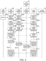
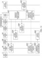
- Fig. 4 is a sequence diagram illustrating an example operation of constructing lines of the control network 11 and the data network 12 (construction of communication paths of a control line and a data line).
- the user of the first arithmetic device 3 connects the first transmission device 2a to the optical transmission line 10 (step S101).
- the first transmission device 2a transmits a connection request to the second transmission device 4 via a connection line.
- the signal of the connection request may include an Internet Protocol (IP) address of the first transmission device 2a, for example.
- the signal of the connection request may include information (information for approval, for example) that has been input beforehand by the user (step S102).
- the second transmission device 4 transmits a connection request to the control server 7 (step S103).
- the control server 7 acquires the connection request, and determines whether to approve or whether to reject connection of the first arithmetic device 3, on the basis of the acquired connection request (step S104).
- the control server 7 transmits an approval notification as a reply to the connection request, to the second transmission device 4 (step S105-1).
- the second transmission device 4 transmits the approval notification as a reply to the connection request, to the first transmission device 2a (step S106-1).
- the first transmission device 2a acquires the approval notification as a reply to the connection request (step S107-1).
- the first transmission device 2a constructs a control line. Constructing a control line means that the setting of the multiplexing/demultiplexing unit 26 of the first transmission device 2a and the setting of the multiplexing/demultiplexing unit 45 of the second transmission device 4 are changed on the basis of an instruction from the control server 7, and communication is enabled between the control server 7 and the device control unit 21.
- the device control unit 21 of the first transmission device 2a receives an instruction from the control server 7 via a connection line set between the connection processing unit 42 and the connection processing unit 23. Eventually, the device control unit 21 changes the setting of the multiplexing/demultiplexing unit 26, on the basis of the instruction. Also, the device control unit 40 of the second transmission device 4 acquires an instruction from the control server 7. The device control unit 40 changes the setting of the multiplexing/demultiplexing unit 45, on the basis of the contents of the instruction.
- both the settings of the multiplexing/demultiplexing unit 26 and the multiplexing/demultiplexing unit 45, and the setting of the control server 7 might be changed. Note that, as in a case where a control signal passes through a control line after its construction, a control signal may be communicated between the first transmission device 2a and the control server 7 via a connection line.
- step S108 An instruction for the first transmission device 2a and a setting change are made in step S108, an instruction for the second transmission device 4 and a setting change are made in step S109, and a setting change to the control server 7 is made in step S110.
- step S110 a setting change to the control server 7 is made in step S110.
- the first transmission device 2a transmits a request for construction of a data network to the control server 7 via the control line (step S111).
- the control server 7 designs a communication path for the data network 12, on the basis of the request for construction of a data network (step S112). On the basis of a result of the communication path design, the control server 7 transmits an instruction to construct a data network (a data line) to the first transmission device 2a (step S113).
- control server 7 each transmission device, and the like construct the data network 12 through the respective example steps described in the following (1) to (4).
- step S114 An instruction to the first transmission device 2a and a setting change are made in step S114, an instruction to the second transmission device 4 and a setting change are made in step S115, and instructions to the third transmission device 5 and the fourth transmission device 6, and setting changes are made in step S116.
- step S115 An instruction to the second transmission device 4 and a setting change are made in step S115, and instructions to the third transmission device 5 and the fourth transmission device 6, and setting changes are made in step S116.
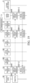
- Fig. 5 is a sequence diagram illustrating an example operation of constructing a line (construction of a communication path for a setting change line) of the customer control network 13.
- the first transmission device 2a transmits a request for construction of a customer control network to the control server 7 via the control line (step S119).
- the control server 7 acquires the request for construction of a customer control network (step S119).
- control server 7 transmits an instruction to construct a customer control network to the first transmission device 2a and the second transmission device 4 (step S121), like the instruction to construct the control network 11 in step S110.
- the device control unit 21 of the first transmission device 2a changes the setting of the multiplexing/demultiplexing unit 26 (step S122).
- the device control unit 40 of the second transmission device 4 changes the setting of the multiplexing/demultiplexing unit 45 (step S123) .
- the customer control server 9 changes the setting of the customer control server 9 so as to enable communication between the first transmission device 2a and the customer control server 9 via the customer control network 13 (step S124).
- a connection between the first transmission device 2a and the customer control server 9 is established via the setting change line and the customer control network 13.
- communication between the first transmission device 2a and the customer control server 9 may be conducted via the setting change communication unit 43.
- the control line is connected to the setting change communication unit 43 via the multiplexing/demultiplexing unit 45.
- the control server 7 transmits a notification of completion of the customer control network construction to the first transmission device 2a (step S125).
- the first transmission device 2a acquires the notification of completion of the customer control network construction (step S126).
- the first transmission device 2a waits for acquisition of a user request (a request to change data, for example) (step S127).
- a user request a request to change data, for example
- Only the control network 11 and the customer control network 13 may be constructed, and the data network 12 may be constructed after a user request.
- the data network 12 may be constructed only for the section between the first transmission device 2a and the second transmission device 4, and the first transmission device 2a, the second transmission device 4 and the third transmission device 5, and the data network 12 may be connected after a user request.
- the customer control network 13 may be constructed first, followed by the data network 12.
- Fig. 6 is a sequence diagram illustrating an example operation of refusing a connection.
- the respective operations from step S101 to step S104 are the same as the respective operations from step S101 to step S104 illustrated in Fig. 4 .
- the control server 7 transmits a refusal notification as a reply to the connection request, to the second transmission device 4 (step S105-2).
- the second transmission device 4 transmits the refusal notification as a reply to the connection request, to the first transmission device 2a (step S106-2).
- the first transmission device 2a acquires the refusal notification as a reply to the connection request (step S107-2).
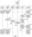
- Fig. 7 is a sequence diagram illustrating an example operation of changing the setting of the data network 12.
- the first arithmetic device 3 transmits an instruction to change the setting of the data network, to the first transmission device 2a (step S201).
- the first transmission device 2a transmits the instruction to change the setting of the data network, to the customer control server 9 via the setting change line (step S202).
- the customer control server 9 acquires the setting change instruction (step S203).
- the customer control server 9 transmits the instruction to change the setting of the data network (a setting request), to the control server 7 (step S204).
- the control server 7 designs a communication path of the data network 12 (step S205). On the basis of a result of the communication path design, the control server 7 transmits an instruction to change the setting of the data network 12 to the devices that need changing the setting (the first transmission device 2a, the second transmission device 4, the third transmission device 5, and the fourth transmission device 6 in this case), like the instruction to construct the data network in step S113 (the respective example steps described above in (1) to (4)) (step S206).
- step S207 An instruction to the first transmission device 2a and a setting change are made in step S207, an instruction to the second transmission device 4 and a setting change are made in step S208, and instructions to the third transmission device 5 and the fourth transmission device 6, and setting changes are made in step S209.
- the control server 7 transmits a notification of completion of the setting change in the data network, to the customer control server 9 (step S210).
- the customer control server 9 acquires the notification of completion of the setting change in the data network (step S211).
- the customer control server 9 transmits the notification of completion of the setting change in the data network, to the first transmission device 2a (step S212).
- the first transmission device 2a transmits the notification of completion of the setting change in the data network, to the first arithmetic device 3 (step S213).
- the first arithmetic device 3 acquires the notification of completion of the setting change in the data network (step S214).
- the communication system 1a includes a plurality of transmission devices.
- the plurality of transmission devices includes the first transmission device 2a and the second transmission device 4.
- the device control unit 40 can communicate with the first transmission device 2a via the optical transmission line 10.
- the device control unit 40 can communicate with the control server 7 via the control network 11.
- the device control unit 40 can communicate with the customer control server 9 via the customer control network 13.
- the connection processing unit 23 performs processing for constructing the control network 11 (the control line) between the first transmission device 2a and the control server 7, using the connection line and the connection processing unit 42. In this manner, the connection processing unit 23 performs the processing for constructing the control network 11 (the control line) between the first transmission device 2a and the control server 7, using the second transmission device 4 as a relay device.
- the device control unit 21 performs processing for constructing a data line between the first transmission device 2a and the data network 12, using the control line and the control server 7. In this manner, the device control unit 21 performs the processing for constructing the data line between the first transmission device 2a and the data network 12, using the second transmission device 4 as a relay device.
- the control server 7 performs a control process related to the first transmission device 2a and the data network 12, on the basis of the data related to the setting of the data network 12.
- the data communication unit 25 performs communication via the optical transmission line 10 (the data line). For example, the data communication unit 25 acquires a data signal transmitted from the data communication unit 44 of the second transmission device 4, via the multiplexing/demultiplexing unit 26 that performs processing according to a predetermined multiplexing method. For example, the data communication unit 25 transmits a data signal transmitted from the first arithmetic unit 31 to the data communication unit 44 of the second transmission device 4, via the multiplexing/demultiplexing unit 26 that performs processing according to a predetermined multiplexing method.
- the setting processing unit 20 Under the control of the device control unit 21, the setting processing unit 20 performs a process of constructing a setting change line of the customer control network 13 between the first transmission device 2a and the customer control server 9, using the second transmission device 4 as a relay device.
- the customer control server 9 receives an instruction to change the setting related to the data network 12, from the setting processing unit 20 via the setting change communication unit 24 and the setting change communication unit 43.
- the customer control server 9 transmits the instruction (a setting request) to change the setting of the data network, to the control server 7.
- three kinds of communication networks which are the control line of the control network 11, the data line of the data network 12 (a data communication network), and the setting change line of the customer control network 13, are automatically constructed. That is, three kinds of communication networks are constructed mainly by the user side, rather than by the communications company.
- the user can quickly use and change communication services. Furthermore, the user's setting instruction generated by a transmission device at an end of the network reaches the customer control server 9 without passing through any external network. Thus, the setting of a transmission device in the network can be changed by the user.
- communication services can be used by the user side preparing a transmission device compatible with the above steps and the communication standard of each communication network, it is possible to lower the costs of the hardware of each transmission device by mass production through generalization or the like. Further, even in a case where the user needs to newly install and change a transmission device, and the setting of the communication equipment is to be changed, the user does not need to prepare another network for changing the setting, and thus, time and costs are saved.
- a second embodiment differs from the first embodiment in that a setting processing unit is provided in the first station 200 (a station of the communications company). In the second embodiment, the differences from the first embodiment are mainly described.
- Fig. 8 is a diagram illustrating an example configuration of a communication system 1b.
- the communication system 1b includes a first transmission device 2b, a first arithmetic device 3, a second transmission device 4, a third transmission device 5, a fourth transmission device 6, a control server 7, a second arithmetic device 8, a customer control server 9, an optical transmission line 10, a control network 11, a data network 12, a customer control network 13, and a management device 14.
- the first transmission device 2b includes a device control unit 21, a control communication unit 22, a connection processing unit 23, a setting change communication unit 24, a data communication unit 25, a multiplexing/demultiplexing unit 26, and an optical signal communication unit 27.
- the data communication unit 25 acquires, from the first arithmetic unit 31, a signal (an instruction from the first arithmetic unit 31) for a setting signal transmitted in a setting change line.
- the instruction from the first arithmetic unit 31 may be transmitted from the first arithmetic unit 31 to the data communication unit 25 by a logical multiplexing method implemented in existing Ethernet (registered trademark).
- This logical multiplexing method involves a method for changing connection destinations in accordance with an IP address, and a format of VLAN multiplexing, for example.
- the setting change communication unit 24 transmits the instruction from the first arithmetic unit 31 to the management device 14, using the setting change line.
- the data communication unit 25 and the management device 14 may be connected to each other through a setting change line path from the data communication unit 25.
- a signal transmitted from the data communication unit 25 includes both the data transmitted through the data line and the data transmitted through the setting change line. Therefore, setting needs to be conducted in the multiplexing/demultiplexing unit 26 and the multiplexing/demultiplexing unit 45 so that the multiplexing/demultiplexing unit 26 and the multiplexing/demultiplexing unit 45 can distinguish those sets of data from each other.
- a connection method by which a plurality of setting change line paths is used in combination may be adopted.
- the management device 14 (a resource allocation device) includes a resource management unit 140 and a setting processing unit 141.
- the management device 14 (a relay device) is provided in the first station 200 (a relay station), for example.
- the setting processing unit 141 is provided in the first station 200 as a functional unit that is separate from the first transmission device 2b.
- the management device 14 is a device that manages allocation of arithmetic resources.
- the arithmetic resources mean the computational resources including a central processing unit (CPU), a memory, and a storage. Note that the arithmetic resources may be in either a physical form or a logical form, may be logical resources in a physical server, or may be logical resources formed with a plurality of servers.
- the arithmetic resources are used in calculation processes related to the setting of the data network 12, for example.
- the resource management unit 140 performs an arithmetic resource allocation process, on the basis of an arithmetic resource allocation request from the control server 7.
- the setting processing unit 141 is generated as an arithmetic resource for the first transmission device 2b, and is allocated by the resource management unit 140.
- the setting processing unit 141 is connected to the setting change communication unit 24 via the setting change communication unit 43.
- the setting processing unit 141 is also connected to the customer control server 9.
- Fig. 9 is a sequence diagram illustrating an example operation of constructing lines of the control network 11 and the data network 12 (construction of communication paths of a control line and a data line).
- the respective operations from step S301 to step S318 are the same as the respective operations from step S101 to step S118 illustrated in Fig. 4 .
- Fig. 10 is a sequence diagram illustrating an example operation of constructing a line of the customer control network 13.
- the respective operations in step S319 and step S320 are the same as the respective operations in step S119 and step S120 illustrated in Fig. 5 .
- the control server 7 transmits a request for allocation of an arithmetic resource to the first arithmetic device 3 connected to the first transmission device 2b, to the resource management unit 140 (step S321).
- the resource management unit 140 acquires the arithmetic resource allocation request (step S322).
- the resource management unit 140 determines the allocation of the requested arithmetic resource amount among the arithmetic resources being managed by the resource management unit 140, on the basis of the contents of the allocation request (step S323). At this stage, if the arithmetic resource that can be managed and used by the resource management unit 140 is less than the arithmetic resource amount requested to be allocated, the resource management unit 140 notifies the control server 7 of a result indicating that the resource allocation is not possible. In this manner, the resource management unit 140 may eliminate the step of constructing the customer control network 13.
- the setting processing unit 141 is generated as the arithmetic resource allocated by the resource management unit 140.
- the setting processing unit 141 may be a process that is performed in an operating system.
- the setting processing unit 141 may be a process or a program that is executed in a container generated by "Docker".
- the setting processing unit 141 may be a program or a process that is performed in a virtual machine.
- the setting processing unit 141 may be a process execution environment of a virtual machine, or may be dynamically generated in a processor and a memory through execution of installation. In a case where the execution environment in which the process is performed is prepared beforehand, the setting processing unit 141 may be allocated to the processor and the memory in response to a setting change or a process start instruction.
- the setting processing unit 141 generated in response to the allocation by the resource management unit 140 receives setting information, and changes the setting of the setting processing unit 141 so that communication with the control server becomes possible (step S324). Note that, in a case where an allocation process including the contents executed in step S324 is performed when the resource management unit 140 generates the setting processing unit 141, the execution of step S324 may be skipped.
- the resource management unit 140 transmits a notification of completion of the arithmetic resource allocation, to the control server 7 (step S326).
- Fig. 11 is a sequence diagram illustrating an example operation of constructing a line of the customer control network 13.
- the control server 7 transmits an instruction to construct a customer control network to the first transmission device 2b, the setting processing unit 141, the second transmission device 4, and the customer control server 9 (step S327), like the instruction to construct the control network 11 in step S110.
- the device control unit 21 of the first transmission device 2b changes the setting of the multiplexing/demultiplexing unit 26 (step S328).
- the setting processing unit 141 constructs the customer control network 13 (step S329).
- the device control unit 40 of the second transmission device 4 changes the setting of the multiplexing/demultiplexing unit 45 (step S330).
- the customer control server 9 changes the setting of the customer control server 9 so as to enable communication between the first transmission device 2b and the customer control server 9 via the customer control network 13 (step S331).
- a connection between the first transmission device 2b and the customer control server 9 is established via the setting change line and the customer control network 13.
- communication between the first transmission device 2b and the customer control server 9 may be conducted via the control communication unit 41.
- the control line is connected to the control communication unit 41 via the multiplexing/demultiplexing unit 45.
- the control server 7 transmits a notification of completion of the customer control network construction to the first transmission device 2b (step S332).
- the first transmission device 2b acquires the notification of completion of the customer control network construction (step S333).
- the first transmission device 2b transmits the notification of completion of the initial construction to the setting processing unit 141 (step S334).
- the setting processing unit 141 waits for acquisition of a user request (a request to change data, for example) (step S335).
- Fig. 12 is a sequence diagram illustrating an example operation of refusing a connection.
- the respective operations from step S301 to step S307-2 are the same as the respective operations from step S101 to step S107-2 illustrated in Fig. 6 .
- Fig. 13 is a sequence diagram illustrating an example operation of changing the setting of the data network 12.
- the first arithmetic device 3 transmits an instruction to change the setting of the data network, to the first transmission device 2b (step S401).
- the first transmission device 2b transmits the instruction to change the setting of the data network, to the setting processing unit 141 via the setting change line (step S402).
- the setting processing unit 141 transmits an instruction to change the setting of the data network, to the customer control server 9 (step S403).
- the customer control server 9 acquires the setting change instruction (step S404).
- step S405 to step S412 are the same as the respective operations from step S204 to step S221 illustrated in Fig. 7 .
- the instruction to change the setting of the data network 12 is executed for devices that need changing the setting, as in Fig. 7 .
- the instruction is transmitted to the first transmission device 2b, the second transmission device 4, the third transmission device 5, and the fourth transmission device 6.
- the customer control server 9 transmits a notification of completion of the setting change in the data network, to the setting processing unit 141 (step S413).
- the setting processing unit 141 transmits the notification of completion of the setting change in the data network, to the first transmission device 2b (step S414).
- the first transmission device 2b transmits the notification of completion of the setting change in the data network, to the first arithmetic device 3 (step S415).
- the first arithmetic device 3 acquires the notification of completion of the setting change in the data network (step S416).
- the setting processing unit 141 is provided in the first station 200 as a functional unit that is separate from the first transmission device 2b.
- the optical transmission line 10 a physical line such as an optical fiber
- three kinds of communication networks which are the control line of the control network 11, the data line of the data network 12, and the setting change line of the customer control network 13, are automatically constructed between the office 100 and the first station 200.
- the user can quickly use and change communication services.
- the user's setting instruction generated by a transmission device at an end of the network reaches the customer control server 9 without passing through any external network.
- the data of a transmission device in the network can be changed by the user. Because of these aspects, the security of the setting processing unit can be increased.
- a third embodiment differs from the second embodiment in that a setting processing unit is provided in a place (the customer control server 9, for example) other than the first station 200.
- the differences from the second embodiment are mainly described.
- Fig. 14 is a diagram illustrating an example configuration of a communication system 1c.
- the communication system 1c includes a first transmission device 2c, a first arithmetic device 3, a second transmission device 4, a third transmission device 5, a fourth transmission device 6, a control server 7, a second arithmetic device 8, a customer control server 9, an optical transmission line 10, a control network 11, a data network 12, a customer control network 13, and a management device 14.
- the management device 14 is provided in a facility where the customer control server 9 is installed (a predetermined station, for example).
- the management device 14 may be provided in a facility (the customer control server 9, for example) determined beforehand as an arithmetic resource of the communications company.
- the setting processing unit 141 is provided as a functional unit separate from the first transmission device 2d in a facility where the customer control server 9 is installed or in the customer control server 9.
- the setting processing unit 141 communicates with the first arithmetic unit 31 via the customer control network 13, the setting change communication unit 43, the setting change line, and the setting change communication unit 24.
- the first arithmetic unit 31 transmits an instruction to change the setting of the data network, to the customer control server 9 via the setting change communication unit 24, the setting change line, the setting change communication unit 43, and the customer control network 13.
- the setting processing unit 141 is provided as a functional unit separate from the first transmission device 2c in a facility where the customer control server 9 is installed (a facility of the communications company, for example) or in the customer control server 9.
- the customer control server 9 is installed (a facility of the communications company, for example) or in the customer control server 9.
- three kinds of communication networks which are the control line of the control network 11, the data line of the data network 12, and the setting change line of the customer control network 13, are automatically constructed between the office 100 and the first station 200.
- the user can quickly use and change communication services.
- the user's setting instruction generated by a transmission device (the first transmission device) at an end of the network reaches the customer control server 9 without passing through any external network.
- the user can change the data of a transmission device in the network.
- the security of the setting processing unit can also be increased.
- a fourth embodiment differs from the second embodiment in that only the input/output device 30 prepared by the user is connected to the first transmission device. In the fourth embodiment, the differences from the second embodiment are mainly described.
- Fig. 15 is a diagram illustrating an example configuration of a communication system 1d.
- the communication system 1d includes a first transmission device 2d, a second transmission device 4, a third transmission device 5, a fourth transmission device 6, a control server 7, a customer control server 9, an optical transmission line 10, a control network 11, a data network 12, a customer control network 13, a management device 14, a management device 15, and an input/output device 30.
- the first transmission device 2d includes a device control unit 21, a control communication unit 22, a connection processing unit 23, a setting change communication unit 24, a data communication unit 25, a multiplexing/demultiplexing unit 26, an optical signal communication unit 27, a signal switching unit 28, and a device connection unit 32.
- the management device 15 (an information processing device) includes a resource management unit 150 and a third arithmetic unit 151.
- the fourth transmission device 6 and the management device 15 are provided in a second station 400 (a relay station), for example.
- the input/output device 30 is connected to the device connection unit 32 by the user. Communication in a case where the third arithmetic unit 151 is operated is now described.
- the input/output device 30 transmits data (operation data) corresponding to an operation received by the input/output device 30, to the device connection unit 32 in the uplink direction.
- the signal switching unit 28 distributes operation data for each input/output device 30, for example, to the data communication unit 25.
- the data communication unit 25 transmits the operation data to the third arithmetic unit 151.
- the data communication unit 25 receives data from the third arithmetic unit 151.
- the data communication unit 25 transmits the data from the third arithmetic unit 151, to the device connection unit 32.
- the device connection unit 32 transmits the data to the input/output device 30.
- HDMI High-Definition Multimedia Interface
- DVI Digital Visual Interface
- USB Universal Serial Bus
- the input/output device 30 transmits data (operation data) corresponding to an operation received by the input/output device 30, to the device connection unit 32 in the uplink direction.
- the signal switching unit 28 distributes operation data for each input/output device 30, for example, to the data communication unit 25.
- the setting change communication unit 24 transmits the operation data to the setting processing unit 141.
- the setting change communication unit 24 receives data from the setting processing unit 141.
- the setting change communication unit 24 transmits the data from the setting processing unit 141, to the device connection unit 32 via the signal switching unit 28.
- the device connection unit 32 transmits the data to the input/output device 30.
- the data to be exchanged between the input/output device 30 and the setting processing unit 141, and the data to be exchanged between the input/output device 30 and the third arithmetic unit 151 may be compatible with the same signal type.
- the distribution at the multiplexing/demultiplexing unit 26 may be performed so that a connection to the setting change communication unit 24 and a connection to the data communication unit 25 are switched by a specific signal from the input/output device 30 operated by the user.
- the specific signal is formed with simultaneous inputs from specific keys on a keyboard, for example. Further, the switching of allocation may be performed with a physical switch provided on the first transmission device 2d.
- the device connection unit 32 may convert a signal being exchanged between the input/output device 30 and the device connection unit 32 into another signal.
- the converted signal may be transmitted to 20 and the data communication unit 25 via the multiplexing/demultiplexing unit 26.
- a signal from 20 and the data communication unit 25 may be converted into a signal for the input/output device 30, and be transmitted to the input/output device 30.
- Another signal is a signal of Ethernet (registered trademark) that is used in a KVM extender or the like, for example.
- a signal transmitted from the data communication unit 25 may be converted into another signal by the second transmission device 4 or the fourth transmission device 6.
- the setting processing unit 141 and the third arithmetic unit 151 may receive the converted signal.
- the second transmission device 4 or the fourth transmission device 6 may convert signals transmitted from the setting processing unit 141 and the third arithmetic unit 151 into signals for the data communication unit 25 of the first transmission device 2d, and then transmit the signals.
- signals between a transmission device, a processing unit, and an arithmetic unit are Ethernet (registered trademark) signals, for example.
- the signals may be of the same type as the signals being exchanged between the input/output device 30 and the device connection unit 32, as long as the signals are compatible with the setting processing unit 141 and the third arithmetic unit 151.
- the type of "another signal” is the same as the type of those signals.
- Fig. 16 is a sequence diagram illustrating an example operation of constructing lines of the control network 11 and the data network 12.
- the respective operations from step S501 to step S518 are the same as the respective operations from step S101 to step S118 illustrated in Fig. 4 .
- Fig. 17 is a sequence diagram illustrating an example operation of constructing a line of the customer control network 13.
- the respective operations from step S519 to step S526 are the same as the respective operations from step S319 to step S326 illustrated in Fig. 10 .
- the setting processing unit 141 allocated as an arithmetic resource has functions corresponding to an arithmetic unit (corresponding to an operating system running in a virtual machine, for example).
- the setting processing unit 141 may also have a function for operating a driver compatible with each signal such as a video signal, a USB signal, and an audio signal. These signals may be transmitted and received directly by the second transmission device 4 and the first transmission device 2d, or may be converted into another signal such as Ethernet (registered trademark) signals and be transmitted and received by the second transmission device 4 and the first transmission device 2d.
- Fig. 18 is a sequence diagram illustrating an example operation of constructing a line of the customer control network 13.
- the respective operations from step S527 to step S535 are the same as the respective operations from step S327 to step S335 illustrated in Fig. 11 .
- Fig. 19 is a sequence diagram illustrating an example operation of refusing a connection.
- the respective operations from step S501 to step S507-2 are the same as the respective operations from step S101 to step S107-2 illustrated in Fig. 6 .
- Fig. 20 is a sequence diagram illustrating an example operation to be performed when an arithmetic resource is allocated as an arithmetic device that is normally used by the user of the input/output device 30.
- the input/output device 30 transmits a request for a connection between the input/output device 30 and the setting processing unit 141, to the first transmission device 2d (step S536).
- This connection request may be a connection request that is made by an input through a specific single key on a keyboard or simultaneous inputs through a plurality of key on the keyboard, for example.
- the first transmission device 2d transmits the connection request to the setting processing unit 141 via the setting change line (step S537).
- the setting processing unit 141 performs a process (a connection process) of establishing a connection between the input/output device 30 and the setting processing unit 141 (step S538).
- the setting processing unit 141 transmits the data (a video signal and an audio signal, for example) necessary for the input/output device 30, to the first transmission device 2d (step S539).
- notification information about the established connection between the setting processing unit 141 and the first transmission device 2d may be included in the data.
- the first transmission device 2d transmits the received data to the corresponding input/output device 30 (the video signal being transmitted to the monitor, the audio signal being transmitted to the speaker, for example) (step S540).
- the input/output device 30 performs a predetermined operation, in accordance with the data transmitted from the first transmission device 2d (step S541). Note that after the connection between the input/output device 30 and the setting processing unit 141 is established, communication may be performed with each other. Further, a signal being communicated may be converted into another signal such as an Ethernet (registered trademark) signal.
- a signal from a keyboard, a mouse, or the like is sent to the setting processing unit 141 by the user referring to screen information or the like displayed on the input/output device 30, so that the setting processing unit 141 is remotely operated in a situation similar to the operation environment in the office, at a geographically separated place (step S542).
- the reason for being "similar to the operation environment" is that the operation environment is affected by the communication state (delayed or the like) due to the physical distance between the office 100 and the first station 200.
- the user operates the input/output device 30, to transmit a request for allocation of the arithmetic resource for the arithmetic device the user normally uses, to the customer control server 9 via the setting processing unit 141.
- the setting processing unit 141 may be able to operate the customer control server 9 in a form such as a browser screen.
- the setting processing unit 141 and the customer control server 9 may be connected when a specific program is activated.
- the setting processing unit 141 transmits, to the customer control server 9, a request for allocation of the arithmetic resource for the arithmetic device the user normally uses (step S543).
- the customer control server 9 acquires the arithmetic resource allocation request (step S544).
- the customer control server 9 transmits the arithmetic resource allocation request to the control server 7 (step S545).
- the control server 7 determines a management device to which the arithmetic resource based on the request can be allocated. Prior to the determination, the control server 7 may check the resource usage status with each management device. Also, the control server 7 may store the resource usage status of each management device as data, and determine the management device on the basis of the stored data.
- the control server 7 transmits the request for allocation of the arithmetic resource for the arithmetic device the user normally uses, to the resource management unit 150 of the determined management device 15 (step S546).
- the resource management unit 150 acquires the arithmetic resource allocation request (step S547).
- the resource management unit 150 performs a process of allocating the arithmetic resource for the arithmetic device the user normally uses (step S548).
- the third arithmetic unit 151 receives the request for allocation of the arithmetic resource for the arithmetic device the user normally uses (step S549).
- the resource management unit 150 transmits a notification of completion of the arithmetic resource allocation, to the control server 7 (step S550).
- the resource management unit 150 acquires the notification of completion of the arithmetic resource allocation (step S551).
- Fig. 21 is a sequence diagram illustrating an example operation of constructing a line between the first transmission device 2d and the third arithmetic unit 151.
- the control server 7 designs the communication path necessary between the first transmission device 2d and the third arithmetic unit 151 (step S552).
- the control server 7 transmits an instruction to change the setting of the data network 12, to the devices that need changing the setting (the first transmission device 2d, the third arithmetic unit 151, the second transmission device 4, and the fourth transmission device 6 in this example) (step S553).
- the first transmission device 2d changes the setting (the communication speed or the modulation method, for example) of the multiplexing/demultiplexing unit 26 and the data communication unit 25 (a data line) (step S554).
- the third arithmetic unit 151 changes the setting of the third arithmetic unit 151 so as to connect to the fourth transmission device 6 (step S555).
- the second transmission device 4 changes the setting of the second transmission device 4 so as to be capable of relaying signals between the data network 12 and the first transmission device 2d (step S556).
- the third transmission device 5 and the fourth transmission device 6 change the settings of the third transmission device 5 and the fourth transmission device 6 so as to enable connection between a signal from the third arithmetic unit 151 and the data network 12 (step S557).
- the control server 7 transmits a notification of completion of the setting change in the data network 12, to the customer control server 9 (step S558).
- the customer control server 9 acquires the notification of completion of the setting change in the data network 12 (step S559) .
- the customer control server 9 transmits a notification of completion of the construction of the data network 12, to the setting processing unit 141 (step S560).
- the user receives the notification to the setting processing unit 141 via the input/output device 30 (steps S561 to S563) .
- Fig. 22 is a sequence diagram illustrating an example operation of switching the connection of input/output device 30.
- the user may switch the connection between the input/output device 30 and the first transmission device 2d for a reason such as a network setting change.
- the input/output device 30 transmits a request for a connection between the input/output device 30 and the setting processing unit 141, to the first transmission device 2d (step S564).
- the first transmission device 2d transmits the connection request to the third arithmetic unit 151 via the connection line (step S565).
- the third arithmetic unit 151 performs a process (a connection process) of establishing a connection between the input/output device 30 and the third arithmetic unit 151 (step S566).
- the distribution at the multiplexing/demultiplexing unit 26 may be performed so that a connection to the setting change communication unit 24 and a connection to the data communication unit 25 are switched by a specific signal from the input/output device 30 operated by the user.
- the specific signal is formed with simultaneous inputs from specific keys on a keyboard, for example. Further, the switching of allocation may be performed with a physical switch provided on the first transmission device 2d.
- the third arithmetic unit 151 transmits a notification of the established connection to the first transmission device 2d (step S567).
- the first transmission device 2d acquires the notification of the established connection.
- the first transmission device 2d transmits a process result based on the notification of the established connection to the input/output device 30 (step S568).
- the input/output device 30 performs a predetermined operation on the basis of the process result based on the notification of the established connection (step S569).
- Fig. 23 is a sequence diagram illustrating an example operation of changing the setting of the data network.
- the respective operations from step S601 to step S606 are the same as the respective operations from step S401 to step S406 illustrated in Fig. 13 .
- the control server 7 transmits an instruction to change the setting of the data network, to the first transmission device 2d, the third arithmetic unit 151, the second transmission device 4, the third transmission device 5, and the fourth transmission device 6 (step S607).
- the first transmission device 2d changes the setting (the communication speed, for example) of the data network (a data line) (step S608).
- the third arithmetic unit 151 changes the setting of the data network 12 (step S609).
- the second transmission device 4 changes the setting of the data network 12 (step S610).
- the third transmission device 5 and the fourth transmission device 6 change the setting of the data network 12 (step S611).
- the control server 7 transmits a notification of completion of the setting change in the data network, to the customer control server 9 (step S612).
- the customer control server 9 acquires the notification of completion of the setting change in the data network (step S613).
- the customer control server 9 transmits a notification of completion of the setting change in the data network, to the setting processing unit 141 (step S614).
- the setting processing unit 141 transmits the notification of completion of the setting change in the data network, to the first transmission device 2d (step S615).
- the first transmission device 2d transmits the notification of completion of the setting change in the data network, to the input/output device 30 (step S616).
- the input/output device 30 acquires the notification of completion of the setting change in the data network (step S617).
- the third arithmetic unit 151 performs a process corresponding to the operation of the input/output device 30.
- the third arithmetic unit 151 transmits the execution result to the first transmission device 2d.
- the first transmission device 2d may transmit the execution result to the input/output device 30.
- three kinds of communication networks which are the control line of the control network 11, the data line of the data network 12, and the setting change line of the customer control network 13, are automatically constructed between the office 100 and the first station 200. With this arrangement, the user can quickly use and change communication services.
- an input/output device 30 (a monitor, a mouse, a speaker, a camera, or any of various sensors, for example) prepared by the user to the first transmission device 2d
- the user can use the input/output device 30. That is, the user can use a virtual personal computer.
- the fourth embodiment is based on the second embodiment, but may be based on the first embodiment or the third embodiment.
- the embodiments may be combined.
- the data network 12 may be connected to the Internet.
- a communication path from the third arithmetic unit 151to the Internet may be separately constructed according to a sequence shown in Fig. 23 so that the third arithmetic unit 151 can be connected to the Internet or the like.
- the third arithmetic unit 151 is connected to a communication path different from the communication path connected to the first arithmetic device 3 and the communication path connected to the Internet.
- the setting processing unit 141 and the third arithmetic unit 151 are constructed under different management devices.
- the positions at which the resources are constructed are not limited to the positions suggested in the fourth embodiment, and both functional units may be constructed in the first station 200, for example. Also, the positions where the resources are constructed may be the opposite of the positions suggested in the fourth embodiment.
- the fourth transmission device 6 may include at least one of the functional units of the second transmission device 4.
- the number of transmission devices included in the communication system is not necessarily three.
- the communication system may include any number of transmission devices. Further, some or all of those transmission devices may include a multiplexing/demultiplexing unit.
- the multiplexing/demultiplexing method for the three kinds of communication networks in a case where an existing technique related to the overhead portion, the payload portion, and the like of an OTU is clearly defined as the technique for multiplexing/demultiplexing, for example, a setting process may be performed without the use of any multiplexing/demultiplexing unit when the specific line networks (a control network, a data network, and a customer control network) are constructed.
- a multiplexing/demultiplexing unit by the existing technique may be used to construct the data network connected to the data line, and the multiplexing/demultiplexing unit 26 and the multiplexing/demultiplexing unit 45 may not be used.
- the series of communication networks are connected to a server or the like from the first transmission device via various communication networks, but an optical signal transmitted through the optical transmission line 10 may be temporarily converted into an electrical signal at a relay point (the second transmission device 4, for example).
- the converted electrical signal may then be transmitted to the communication network to which the corresponding server and device belong.
- the converted electrical signal may be further converted into another optical signal and be transmitted. Note that such transmission also applies to signals to be transmitted from various servers to the first transmission device side. Also, such signals may be converted one or more times at a relay point.
- a communication unit and a processing unit may operate as an integrated functional unit.
- the connection processing unit 23 and the control communication unit 22 may operate as an integrated functional unit.
- the connection processing unit 42 and the control communication unit 41 may operate as an integrated functional unit.
- Fig. 24 is a diagram illustrating an example hardware configuration of the first transmission device 2 in each embodiment.
- the first transmission device 2 corresponds to each of the first transmission device 2a, the first transmission device 2b, the first transmission device 2c, and the first transmission device 2d.
- Some or all of the functional units of the first transmission device 2 are formed as software by a processor 101 such as a CPU executing a program stored in a storage device 103 including a nonvolatile recording medium (non-transitory recording medium) and a memory 102.
- the program may be recorded in a computer-readable recording medium.
- the computer-readable recording medium is a portable medium such as a flexible disk, a magneto-optical disc, a read-only memory (ROM), or a compact disc read-only memory (CD-ROM), or a non-transitory recording medium such as a storage device like a hard disk installed in a computer system, for example.
- a communication unit 104 may acquire the program.
- Some or all of the functional units of the first transmission device 2 may be formed with hardware including an electronic circuit (circuitry) in which a large-scale integrated circuit (LSI), an application specific integrated circuit (ASIC), a programmable logic device (PLD), a field programmable gate array (FPGA), or the like is used, for example.
- LSI large-scale integrated circuit
- ASIC application specific integrated circuit
- PLD programmable logic device
- FPGA field programmable gate array
- the present invention can be applied to optical communication systems.
Landscapes
- Engineering & Computer Science (AREA)
- Computer Networks & Wireless Communication (AREA)
- Signal Processing (AREA)
- Computing Systems (AREA)
- Physics & Mathematics (AREA)
- Electromagnetism (AREA)
- Data Exchanges In Wide-Area Networks (AREA)
Applications Claiming Priority (1)
| Application Number | Priority Date | Filing Date | Title |
|---|---|---|---|
| PCT/JP2021/024338 WO2023275930A1 (ja) | 2021-06-28 | 2021-06-28 | 通信システム、通信方法及びプログラム |
Publications (3)
| Publication Number | Publication Date |
|---|---|
| EP4366263A1 true EP4366263A1 (de) | 2024-05-08 |
| EP4366263A4 EP4366263A4 (de) | 2025-04-09 |
| EP4366263B1 EP4366263B1 (de) | 2025-12-10 |
Family
ID=84691003
Family Applications (1)
| Application Number | Title | Priority Date | Filing Date |
|---|---|---|---|
| EP21948244.5A Active EP4366263B1 (de) | 2021-06-28 | 2021-06-28 | Kommunikationssystem, kommunikationsverfahren und programm |
Country Status (5)
| Country | Link |
|---|---|
| US (1) | US12494964B2 (de) |
| EP (1) | EP4366263B1 (de) |
| JP (1) | JP7549279B2 (de) |
| CN (1) | CN117378181A (de) |
| WO (1) | WO2023275930A1 (de) |
Family Cites Families (11)
| Publication number | Priority date | Publication date | Assignee | Title |
|---|---|---|---|---|
| DE60139431D1 (de) * | 2000-03-17 | 2009-09-10 | Digital Electronics Corp | Steuerungsserver, Steuerungsendgerät, Steuerungssystem und Speichersteuerungskommunikationsprogramm für Aufzeichnungsmedien |
| JP4009945B2 (ja) | 2002-11-25 | 2007-11-21 | 日本電信電話株式会社 | オプティカルvpnサービスにおけるカスタマコントロール方法とネットワークノード装置およびそのプログラム |
| JP2008182293A (ja) | 2007-01-23 | 2008-08-07 | Japan It Resource Market Co Ltd | オンデマンドのip通信帯域幅の制御装置 |
| US8989591B2 (en) * | 2012-06-06 | 2015-03-24 | Techsys Insights | Remote optical demarcation point |
| JP2014099750A (ja) | 2012-11-14 | 2014-05-29 | Mitsubishi Electric Corp | 親局装置、制御装置、帯域比設定装置、光通信システムおよび帯域割当方法 |
| JP5967173B2 (ja) * | 2014-01-31 | 2016-08-10 | 株式会社バッファロー | ネットワーク中継装置、ネットワーク中継装置が有するパケット中継処理部の動作モードを設定する方法、およびコンピュータープログラム |
| JP6996178B2 (ja) * | 2017-09-12 | 2022-01-17 | 株式会社リコー | 機器管理システム、機器管理方法およびプログラム |
| EP3799361B1 (de) | 2018-06-29 | 2025-03-19 | Nippon Telegraph And Telephone Corporation | Verfahren zur dienstinitiierung und kommunikationssystem |
| JP7247848B2 (ja) | 2019-10-10 | 2023-03-29 | 住友電気工業株式会社 | Ponシステム、管理サーバ、管理方法、及び設置方法 |
| WO2021168727A1 (en) * | 2020-02-27 | 2021-09-02 | Juniper Networks, Inc. | Packet steering to a host-based firewall in virtualized environments |
| US11611486B2 (en) * | 2021-04-26 | 2023-03-21 | Verizon Patent And Licensing Inc. | Method and system for deployment and management of composite applications |
-
2021
- 2021-06-28 CN CN202180098404.7A patent/CN117378181A/zh active Pending
- 2021-06-28 JP JP2023531147A patent/JP7549279B2/ja active Active
- 2021-06-28 US US18/565,892 patent/US12494964B2/en active Active
- 2021-06-28 EP EP21948244.5A patent/EP4366263B1/de active Active
- 2021-06-28 WO PCT/JP2021/024338 patent/WO2023275930A1/ja not_active Ceased
Also Published As
| Publication number | Publication date |
|---|---|
| US20240275671A1 (en) | 2024-08-15 |
| EP4366263B1 (de) | 2025-12-10 |
| EP4366263A4 (de) | 2025-04-09 |
| JP7549279B2 (ja) | 2024-09-11 |
| CN117378181A (zh) | 2024-01-09 |
| US12494964B2 (en) | 2025-12-09 |
| WO2023275930A1 (ja) | 2023-01-05 |
| JPWO2023275930A1 (de) | 2023-01-05 |
Similar Documents
| Publication | Publication Date | Title |
|---|---|---|
| EP3364605A1 (de) | Datenzentrumnetzwerksystem und signalübertragungssystem | |
| US9532119B2 (en) | Apparatus and method for transporting optical channel data unit ODU service | |
| US20160007103A1 (en) | Optical Channel Data Unit Service Transmission Apparatus and Method | |
| EP1965601B1 (de) | System und Verfahren zur optischen Übertragung | |
| EP3012986A1 (de) | Querverbindungsvorrichtungen für optische kommunikation und signalverarbeitungsverfahren dafür | |
| WO2020001127A1 (zh) | 使用灵活光网络的业务传输方法、装置、设备及存储介质 | |
| EP4366263B1 (de) | Kommunikationssystem, kommunikationsverfahren und programm | |
| JP2014123892A (ja) | ビットレート可変機能を含む光伝送装置 | |
| CN105577319A (zh) | 通过光通道传输单元信号发送、接收信号的方法及装置 | |
| JP4818815B2 (ja) | 光通信方法、光通信ネットワークシステム、親局光通信装置、子局光通信装置 | |
| US9806909B2 (en) | Data switching apparatus and system | |
| JP2018078407A (ja) | 光集線ネットワークシステム及び信号伝送方法 | |
| JP4368716B2 (ja) | 通信回路および通信方法 | |
| US20150244464A1 (en) | Operating a Node in an Optical Transport Network | |
| CN112653534B (zh) | 一种时隙对齐方法、装置、设备及计算机可读存储介质 | |
| JP5663620B2 (ja) | ネットワーク試験装置及びネットワーク試験方法 | |
| JP5450219B2 (ja) | デジタルクロスコネクト装置及び方法 | |
| JP3734762B2 (ja) | Wdm装置 | |
| JP2017204821A (ja) | 光集線ネットワークシステム、光伝送装置及び光伝送方法 | |
| JP6506209B2 (ja) | 光集線ネットワークシステム、光伝送装置及び光伝送方法 | |
| JPH11266233A (ja) | 光波長多重化装置の光出力レベル制御装置 | |
| JP2002217946A (ja) | ハイブリットスイッチ装置 | |
| JP2008227647A (ja) | 多重化トランスポンダ、通信システム及び信号多重化方法 | |
| US20240187763A1 (en) | Transmission apparatus, path setting method and computer program | |
| EP1107494A2 (de) | Verfahren und Vorrichtung zur Übermittlung von Verwaltungsnachrichten |
Legal Events
| Date | Code | Title | Description |
|---|---|---|---|
| STAA | Information on the status of an ep patent application or granted ep patent |
Free format text: STATUS: THE INTERNATIONAL PUBLICATION HAS BEEN MADE |
|
| PUAI | Public reference made under article 153(3) epc to a published international application that has entered the european phase |
Free format text: ORIGINAL CODE: 0009012 |
|
| STAA | Information on the status of an ep patent application or granted ep patent |
Free format text: STATUS: REQUEST FOR EXAMINATION WAS MADE |
|
| 17P | Request for examination filed |
Effective date: 20231128 |
|
| AK | Designated contracting states |
Kind code of ref document: A1 Designated state(s): AL AT BE BG CH CY CZ DE DK EE ES FI FR GB GR HR HU IE IS IT LI LT LU LV MC MK MT NL NO PL PT RO RS SE SI SK SM TR |
|
| DAV | Request for validation of the european patent (deleted) | ||
| DAX | Request for extension of the european patent (deleted) | ||
| REG | Reference to a national code |
Ref legal event code: R079 Ipc: H04L0012120000 Ref country code: DE Ref legal event code: R079 Ref document number: 602021044385 Country of ref document: DE Free format text: PREVIOUS MAIN CLASS: H04L0045000000 Ipc: H04L0012120000 |
|
| A4 | Supplementary search report drawn up and despatched |
Effective date: 20250311 |
|
| RIC1 | Information provided on ipc code assigned before grant |
Ipc: H04L 12/12 20060101AFI20250305BHEP |
|
| GRAP | Despatch of communication of intention to grant a patent |
Free format text: ORIGINAL CODE: EPIDOSNIGR1 |
|
| STAA | Information on the status of an ep patent application or granted ep patent |
Free format text: STATUS: GRANT OF PATENT IS INTENDED |
|
| INTG | Intention to grant announced |
Effective date: 20250728 |
|
| RIC1 | Information provided on ipc code assigned before grant |
Ipc: H04L 12/12 20060101AFI20250721BHEP |
|
| RAP3 | Party data changed (applicant data changed or rights of an application transferred) |
Owner name: NTT, INC. |
|
| GRAS | Grant fee paid |
Free format text: ORIGINAL CODE: EPIDOSNIGR3 |
|
| GRAA | (expected) grant |
Free format text: ORIGINAL CODE: 0009210 |
|
| STAA | Information on the status of an ep patent application or granted ep patent |
Free format text: STATUS: THE PATENT HAS BEEN GRANTED |
|
| AK | Designated contracting states |
Kind code of ref document: B1 Designated state(s): AL AT BE BG CH CY CZ DE DK EE ES FI FR GB GR HR HU IE IS IT LI LT LU LV MC MK MT NL NO PL PT RO RS SE SI SK SM TR |
|
| REG | Reference to a national code |
Ref country code: CH Ref legal event code: F10 Free format text: ST27 STATUS EVENT CODE: U-0-0-F10-F00 (AS PROVIDED BY THE NATIONAL OFFICE) Effective date: 20251210 Ref country code: GB Ref legal event code: FG4D |
|
| REG | Reference to a national code |
Ref country code: DE Ref legal event code: R096 Ref document number: 602021044385 Country of ref document: DE |
|
| REG | Reference to a national code |
Ref country code: IE Ref legal event code: FG4D |
|
| PG25 | Lapsed in a contracting state [announced via postgrant information from national office to epo] |
Ref country code: ES Free format text: LAPSE BECAUSE OF FAILURE TO SUBMIT A TRANSLATION OF THE DESCRIPTION OR TO PAY THE FEE WITHIN THE PRESCRIBED TIME-LIMIT Effective date: 20251210 |
|
| REG | Reference to a national code |
Ref country code: LT Ref legal event code: MG9D |
|
| PG25 | Lapsed in a contracting state [announced via postgrant information from national office to epo] |
Ref country code: NO Free format text: LAPSE BECAUSE OF FAILURE TO SUBMIT A TRANSLATION OF THE DESCRIPTION OR TO PAY THE FEE WITHIN THE PRESCRIBED TIME-LIMIT Effective date: 20260310 |
|
| PG25 | Lapsed in a contracting state [announced via postgrant information from national office to epo] |
Ref country code: FI Free format text: LAPSE BECAUSE OF FAILURE TO SUBMIT A TRANSLATION OF THE DESCRIPTION OR TO PAY THE FEE WITHIN THE PRESCRIBED TIME-LIMIT Effective date: 20251210 Ref country code: HR Free format text: LAPSE BECAUSE OF FAILURE TO SUBMIT A TRANSLATION OF THE DESCRIPTION OR TO PAY THE FEE WITHIN THE PRESCRIBED TIME-LIMIT Effective date: 20251210 |
|
| REG | Reference to a national code |
Ref country code: NL Ref legal event code: MP Effective date: 20251210 |
|
| PG25 | Lapsed in a contracting state [announced via postgrant information from national office to epo] |
Ref country code: RS Free format text: LAPSE BECAUSE OF FAILURE TO SUBMIT A TRANSLATION OF THE DESCRIPTION OR TO PAY THE FEE WITHIN THE PRESCRIBED TIME-LIMIT Effective date: 20260310 |
|
| PG25 | Lapsed in a contracting state [announced via postgrant information from national office to epo] |
Ref country code: LV Free format text: LAPSE BECAUSE OF FAILURE TO SUBMIT A TRANSLATION OF THE DESCRIPTION OR TO PAY THE FEE WITHIN THE PRESCRIBED TIME-LIMIT Effective date: 20251210 |