EP4357269A1 - Verpackungseinheit mit einem installationselement für einen sanitaerartikel - Google Patents
Verpackungseinheit mit einem installationselement für einen sanitaerartikel Download PDFInfo
- Publication number
- EP4357269A1 EP4357269A1 EP23204495.8A EP23204495A EP4357269A1 EP 4357269 A1 EP4357269 A1 EP 4357269A1 EP 23204495 A EP23204495 A EP 23204495A EP 4357269 A1 EP4357269 A1 EP 4357269A1
- Authority
- EP
- European Patent Office
- Prior art keywords
- front panel
- mounting frame
- plate
- packaging
- side plate
- Prior art date
- Legal status (The legal status is an assumption and is not a legal conclusion. Google has not performed a legal analysis and makes no representation as to the accuracy of the status listed.)
- Pending
Links
- 238000004806 packaging method and process Methods 0.000 title claims abstract description 98
- 238000009434 installation Methods 0.000 title claims abstract description 37
- 239000002184 metal Substances 0.000 description 32
- 230000003014 reinforcing effect Effects 0.000 description 12
- 238000005253 cladding Methods 0.000 description 11
- 239000006260 foam Substances 0.000 description 9
- 239000000853 adhesive Substances 0.000 description 6
- 230000001070 adhesive effect Effects 0.000 description 6
- 229910052602 gypsum Inorganic materials 0.000 description 6
- 239000010440 gypsum Substances 0.000 description 6
- 239000004033 plastic Substances 0.000 description 6
- 238000011010 flushing procedure Methods 0.000 description 4
- 239000004793 Polystyrene Substances 0.000 description 3
- 208000018459 dissociative disease Diseases 0.000 description 3
- 238000005516 engineering process Methods 0.000 description 3
- 239000004794 expanded polystyrene Substances 0.000 description 3
- 239000000835 fiber Substances 0.000 description 3
- 238000000465 moulding Methods 0.000 description 3
- -1 plasterboard Substances 0.000 description 3
- 229920002223 polystyrene Polymers 0.000 description 3
- 239000002023 wood Substances 0.000 description 3
- 239000004744 fabric Substances 0.000 description 2
- 239000003365 glass fiber Substances 0.000 description 2
- 239000007788 liquid Substances 0.000 description 2
- 239000004570 mortar (masonry) Substances 0.000 description 2
- 239000004568 cement Substances 0.000 description 1
- 230000001419 dependent effect Effects 0.000 description 1
- 238000007689 inspection Methods 0.000 description 1
- 229920003002 synthetic resin Polymers 0.000 description 1
- 239000000057 synthetic resin Substances 0.000 description 1
- XLYOFNOQVPJJNP-UHFFFAOYSA-N water Substances O XLYOFNOQVPJJNP-UHFFFAOYSA-N 0.000 description 1
Images

Classifications
-
- B—PERFORMING OPERATIONS; TRANSPORTING
- B65—CONVEYING; PACKING; STORING; HANDLING THIN OR FILAMENTARY MATERIAL
- B65D—CONTAINERS FOR STORAGE OR TRANSPORT OF ARTICLES OR MATERIALS, e.g. BAGS, BARRELS, BOTTLES, BOXES, CANS, CARTONS, CRATES, DRUMS, JARS, TANKS, HOPPERS, FORWARDING CONTAINERS; ACCESSORIES, CLOSURES, OR FITTINGS THEREFOR; PACKAGING ELEMENTS; PACKAGES
- B65D85/00—Containers, packaging elements or packages, specially adapted for particular articles or materials
- B65D85/62—Containers, packaging elements or packages, specially adapted for particular articles or materials for stacks of articles; for special arrangements of groups of articles
-
- E—FIXED CONSTRUCTIONS
- E03—WATER SUPPLY; SEWERAGE
- E03D—WATER-CLOSETS OR URINALS WITH FLUSHING DEVICES; FLUSHING VALVES THEREFOR
- E03D11/00—Other component parts of water-closets, e.g. noise-reducing means in the flushing system, flushing pipes mounted in the bowl, seals for the bowl outlet, devices preventing overflow of the bowl contents; devices forming a water seal in the bowl after flushing, devices eliminating obstructions in the bowl outlet or preventing backflow of water and excrements from the waterpipe
- E03D11/13—Parts or details of bowls; Special adaptations of pipe joints or couplings for use with bowls, e.g. provisions in bowl construction preventing backflow of waste-water from the bowl in the flushing pipe or cistern, provisions for a secondary flushing, for noise-reducing
- E03D11/14—Means for connecting the bowl to the wall, e.g. to a wall outlet
- E03D11/143—Mounting frames for toilets and urinals
- E03D11/146—Mounting frames for toilets and urinals with incorporated cistern
Definitions
- the present invention relates to a packaging unit with an installation element for a sanitary article.
- a sanitary article such as a toilet, a bidet and/or a washstand can be attached to the installation element.
- the installation element can be used to attach the sanitary article to a wall of a building.
- the installation element has a mounting frame that can be attached to the wall.
- the mounting frame is covered with at least one panel so that it is no longer visible after the installation element has been installed. Covering elements, such as tiles, can be attached to the panel.
- the panels are large and must be cut to size when the installation element is installed. This makes the panels heavy and difficult to transport. Cutting the panels to size is also time-consuming.
- the object of the invention is therefore to at least partially solve the problems described with reference to the prior art and in particular to provide a packaging unit by means of which the effort for transporting and cutting can be at least reduced.
- the packaging unit is in particular a combination of at least one installation element and at least one front panel in an outer packaging.
- the packaging unit can form a sales unit and/or serve to improve handling or transportability of the installation element and/or the at least one front panel.
- the outer packaging can be at least partially cuboid-shaped and/or designed in the manner of a container, a box or cartons.
- the outer packaging can consist at least partially of cardboard, corrugated cardboard, film, plastic, wood and/or metal.
- the outer packaging can at least partially or completely surround the installation element and the at least one front panel.
- the installation element and the at least one front panel can be arranged in the outer packaging.
- the outer packaging can have an outer packaging length of, for example, 1,008 mm to 1,408 mm, preferably 1,158 mm to 1,208 mm, particularly preferably (essentially) 1,178 mm, (in particular orthogonal to the outer packaging length), an outer packaging width of, for example, 416 mm to 616 mm, preferably 506 mm to 556 mm, particularly preferably (essentially) 518 mm, (in particular orthogonal to the outer packaging length and/or the outer packaging width), an outer packaging depth of, for example, 100 mm to 400 mm and/or an outer packaging thickness of, for example, 1 mm to 10 mm, preferably 1 mm to 5 mm, particularly preferably (essentially) 1.5 mm to 2 mm.
- an outer packaging length of, for example, 1,008 mm to 1,408 mm, preferably 1,158 mm to 1,208 mm, particularly preferably (essentially) 1,178 mm, (in particular orthogonal to the outer packaging length)
- an outer packaging width of, for example, 416
- the installation element is used to attach a sanitary article, in particular a water-conducting one, to a floor of a building and/or a wall of the building.
- the sanitary article can be, for example, a toilet, a urinal, a shower-toilet, a bidet or a washbasin.
- the installation element has a mounting frame to which the sanitary article can be fastened.
- the mounting frame can, for example, comprise at least one metal profile.
- the mounting frame can, for example, have a (vertical) first metal profile and a (vertical) second metal profile, which are connected to one another via at least one (horizontal) third metal profile and/or at least one (metal) cross member.
- the first metal profile, the second metal profile and/or the third metal profile can, for example, be connected to one another via a welded connection or screw connection.
- the first metal profile, the second metal profile and/or the third metal profile can be formed in one piece.
- the mounting frame can (in particular after its (vertical) fastening to the wall in a horizontal direction) have a frame width of, for example, 400 mm [millimeters] to 600 mm, preferably 490 mm to 510 mm, particularly preferably (essentially) 500 mm.
- the mounting frame can be height-adjustable. This can mean that a frame height of the mounting frame is adjustable (in particular in a vertical direction).
- the mounting frame can have at least one adjustable foot.
- the mounting frame can have a first foot that is adjustable on and/or in the (vertical) first metal profile.
- the mounting frame can have a second foot that is adjustable on and/or in the (vertical) second metal profile.
- the frame height can be, for example, 1,000 mm to 1,400 mm, preferably 1,130 mm to 1,330 mm.
- the frame height can be measured in the vertical direction, in particular after the installation element or the mounting frame has been mounted on the wall and/or on the floor.
- the mounting frame can be attached to the wall or to the wall at a distance from the wall.
- the mounting frame can be attached to the wall via at least one wall fastening element.
- the distance from the wall can be, for example, 100 mm to 400 mm, preferably 135 mm to 250 mm, particularly preferably 135 mm to 230 mm.
- the mounting frame can have at least one fastening element for the sanitary article, which is designed, for example, in the manner of a metal rod or threaded rod.
- the mounting frame has in particular a plurality of fastening elements for the sanitary article, wherein the fastening elements can in particular be arranged at a distance from one another and/or at the same height.
- the at least one fastening element can in particular be fastened to the at least one cross member of the mounting frame.
- the installation element can comprise a cistern for receiving a flushing liquid for flushing the sanitary article.
- the cistern can be attached to the mounting frame.
- the packaging unit comprises at least one front panel with which a front of the mounting frame can be at least partially covered, in particular after the mounting frame has been attached to the wall.
- the front of the mounting frame faces in particular in the direction of the sanitary article after the installation element has been installed.
- a rear side of the mounting frame faces in particular in the direction of the wall after the installation element has been installed.
- the front and rear of the mounting frame can be opposite each other.
- “Coverable" can be understood to mean that the front of the mounting frame can be at least partially covered by the at least one front panel, so that the mounting frame is at least partially no longer visible after the installation element has been installed on the wall.
- the at least one front panel or each of the front panels can extend from the (vertical) first metal profile to the (vertical) second metal profile of the mounting frame.
- the at least one front panel can at least partially cover the (vertical) first metal profile and the (vertical) second metal profile of the mounting frame.
- the at least one front panel can (in The at least one front panel can be designed or cut to size (essentially) rectangular.
- the at least one front panel can have a panel thickness of, for example, 10 mm to 50 mm, preferably 10 mm to 30 mm, particularly preferably (essentially) 20 mm.
- the packaging unit can have a plurality of front panels, for example a first front panel and a second front panel.
- the plurality of front panels can be connected to one another by means of connecting elements, tongue and groove systems, insert moldings and/or puzzle technology.
- the at least one front panel and/or a core of the at least one front panel can consist at least partially of gypsum, gypsum fiber, plasterboard, wood, plastic, rigid foam and/or foam.
- the rigid foam can be, for example, expanded polystyrene (EPS) or extruded polystyrene (XPS).
- the at least one front panel can be reinforced with a reinforcing layer on a front side and/or rear side.
- the front side can be an outside of the at least one front panel, an outward-facing side of the at least one front panel, a side of the at least one front panel oriented in the direction of the sanitary article and/or a fastening surface of the at least one front panel for the at least one cladding element.
- the rear side can be an inside of the at least one front panel, an inward-facing side of the at least one front panel, a side of the at least one front panel oriented in the direction of the mounting frame and/or a fastening surface of the at least one front panel for the mounting frame.
- the reinforcing layer can consist at least partially of a glass fiber fabric, mortar, cement, synthetic resin and/or plastic.
- the reinforcing layer can be at least partially a mortar layer reinforced with glass fiber fabric.
- the reinforcing layer can have a layer thickness of, for example, 0.1 mm to 5 mm, preferably 1 mm to 3 mm, particularly preferably (essentially) 2 mm, on the front side and/or rear side.
- the reinforcing layer can extend over an entire surface of the front side of the at least one front panel.
- the reinforcing layer can extend over an entire surface of the rear side of the at least one front panel.
- the at least one front panel or the plurality of front panels can be arranged in a packaging.
- the packaging can be at least partially cuboid-shaped and/or designed in the manner of a container, a box or a carton.
- the packaging can consist at least partially of cardboard, corrugated cardboard, film, plastic, wood and/or metal.
- the packaging can at least partially or completely surround the at least one front panel.
- the at least one front panel can be arranged in a (first) interior space of the packaging.
- the packaging can have a packaging length of, for example, 908 mm to 1,108 mm, preferably 1,008 mm to 1,058 mm, particularly preferably (essentially) 1,034 mm to 1,038 mm, (in particular orthogonal to the packaging length), a packaging width of, for example, 408 mm to 608 mm, preferably 498 mm to 548 mm, particularly preferably (essentially) 508 mm to 512 mm, (in particular orthogonal to the packaging length and/or the packaging width), a packaging depth of, for example, 38 mm to 166 mm, preferably 38 mm to 98 mm, particularly preferably (essentially) 67 mm to 71 mm, and/or a packaging thickness of, for example, 1 mm to 10 mm, preferably 1 mm to 5 mm, particularly preferably (essentially) 1.5 mm to 2 mm.
- the packaging with the at least one front panel can be arranged as a panel packaging unit in the outer packaging.
- the at least one front panel can be fastened (in particular directly) to the mounting frame or to the front of the mounting frame.
- the at least one front panel can be fastened, for example, using an adhesive connection, a screw connection, a plug connection, a welded connection and/or a clamp connection.
- At least one cladding element for example in the manner of a tile, can be fastened to a front side or outside of the at least one front panel.
- the at least one cladding element can be fastened, for example, using an adhesive connection.
- the at least one front panel has a front panel width that deviates from the frame width of the mounting frame by a maximum of 50 mm, preferably a maximum of 40 mm, particularly preferably a maximum of 5 mm.
- the front panel width can be measured (in particular after mounting the installation element or the mounting frame on the wall and/or on the floor) in a horizontal direction and/or in the same direction as the frame width of the mounting frame.
- the front panel has a front panel width that is a maximum of 50 mm, preferably a maximum of 40 mm, particularly preferably a maximum of 5 mm, greater than the frame width of the mounting frame.
- the front panel width can correspond (essentially) to the frame width of the mounting frame plus twice the panel thickness or panel thickness.
- the front panel width can correspond (essentially) to the frame width of the mounting frame.
- the at least one front panel for example as an accessory, can be arranged with the installation element in the outer packaging, in particular without the size of the outer packaging having to be (significantly) increased.
- storage spaces and/or warehouses in retail do not have to be adapted to a changed size of the outer packaging.
- at least one front panel is easier to handle and/or cut to size.
- the front panel width can be 400 mm to 600 mm.
- the front panel width can be 490 mm to 540 mm, particularly preferably (essentially) 500 mm.
- the packaging unit can have a first front panel and a second front panel, which can be used to cover the entire front of the mounting frame. This can mean, for example, that the first front panel and the second front panel are cut in such a way that they can be used together to cover the entire front of the mounting frame.
- a first front panel height of a first front panel and a second front panel height of a second front panel can deviate in total by a maximum of 50 mm, preferably a maximum of 40 mm, particularly preferably a maximum of 5 mm, from a frame height of the mounting frame.
- the sum of the first front panel height and the second front panel height can (essentially) be the The first front panel height and/or second front panel height can be measured (particularly after mounting the installation element or the mounting frame on the wall and/or on the floor) in the vertical direction and/or in the same direction as the frame height of the mounting frame.
- a first front panel can have a first front panel height of 300 mm to 500 mm, preferably 350 mm to 400 mm, particularly preferably (substantially) 370 mm.
- a second front panel may have a second front panel height of 700 to 900 mm, preferably 780 mm to 820 mm, particularly preferably (substantially) 800 mm.
- a first front panel height of a first front panel and a second front panel height of a second front panel can total 1,000 mm to 1,400 mm, preferably 1,130 mm to 1,330 mm, particularly preferably (essentially) 1,170 mm.
- the packaging unit can have at least one side plate for at least partially covering at least one side of the mounting frame.
- the at least one side of the mounting frame can be at least partially covered with the at least one side plate, in particular after the mounting frame has been attached to the wall.
- the at least one side can be a right side and/or left side of the mounting frame.
- the left side and the right side of the mounting frame can be opposite each other.
- the at least one side can run orthogonally to the front of the mounting frame.
- “Coverable" can be understood to mean that the at least one side of the mounting frame can be at least partially covered by the at least one side plate, so that the mounting frame is at least partially no longer visible after the installation element has been installed on the wall.
- the at least one side plate or each of the side plates can extend at least partially along the (vertical) first metal profile or along the (vertical) second metal profile of the mounting frame.
- the at least one side plate can cover the (vertical) first Metal profile and/or the (vertical) second metal profile of the mounting frame at least partially cover.
- the at least one side plate can be (essentially) rectangular in shape or cut to size.
- the at least one side plate can have a plate thickness of, for example, 10 mm to 50 mm, preferably 10 mm to 30 mm, particularly preferably (essentially) 20 mm.
- the packaging unit can have a plurality of side plates, for example a first side plate, second side plate, third side plate and fourth side plate.
- the plurality of side plates can be connected to one another by means of the connecting elements, tongue and groove systems, insert moldings and/or puzzle technology.
- the at least one side plate and/or a core of the at least one side plate can consist at least partially of gypsum, gypsum fiber, plasterboard, wood, plastic, rigid foam and/or foam.
- the rigid foam can be, for example, expanded polystyrene (EPS) or extruded polystyrene (XPS).
- the at least one side plate can be reinforced with the reinforcing layer on a front side and/or a back side.
- the front side can be an outer side of the at least one side plate, an outward-facing side of the at least one side plate and/or a fastening surface of the at least one side plate for the at least one cladding element.
- the back side can be an inner side of the at least one side plate, an inward-facing side of the at least one side plate, a side of the at least one side plate oriented in the direction of the mounting frame and/or a fastening surface of the at least one side plate for the mounting frame.
- the reinforcing layer can extend over an entire surface of the front side of the at least one side plate.
- the reinforcing layer can extend over an entire surface of the back side of the at least one side plate.
- the at least one side plate or the plurality of side plates can be arranged in the packaging.
- the at least one side plate can be arranged in the (first) interior of the packaging.
- the packaging with the at least one front plate and the At least one side plate can be arranged as a plate packaging unit in the outer packaging.
- the at least one side plate can be fastened (in particular directly) to the mounting frame or to at least one side of the mounting frame.
- the at least one side plate can be fastened, for example, using an adhesive connection, a screw connection, a plug connection, a welded connection and/or a clamp connection.
- At least one cladding element can be fastened to a front side or outside of the at least one side plate.
- the at least one cladding element can be fastened, for example, using an adhesive connection.
- the at least one side plate or each of the side plates can be (essentially) rectangular in shape or cut to size.
- the at least one side plate or each of the side plates can have a side plate width of, for example, 50 mm to 400 mm.
- the side plate width can preferably be 200 mm to 300 mm, particularly preferably (essentially) 250 mm.
- the side plate width can be measured (in particular after the installation element or the mounting frame has been mounted on the wall and/or on the floor) in the horizontal direction and/or orthogonal to the wall.
- the at least one side plate or each of the side plates can have a side plate height of, for example, 510 mm to 710 mm, preferably 575 mm to 620 mm, particularly preferably (essentially) 595 mm.
- the side panel height can be measured (particularly after mounting the installation element or the mounting frame on the wall and/or on the floor) in the vertical direction and/or in the same direction as the frame height of the mounting frame. All side panels can have the same side panel width and/or the same side panel height. All side panels can be (essentially) identical.
- At least the entire left side of the mounting frame can be covered with the first side plate and the second side plate and/or at least the entire right side of the mounting frame can be covered with the third side plate and the fourth side plate.
- the first side plate and the second side plate can be cut in such a way that the entire left side of the mounting frame can be covered by them together.
- the third side plate and the fourth side plate can be cut in such a way that the entire right side of the mounting frame can be covered by them together.
- the packaging unit can have at least one cover plate for at least partially covering an upper side of the mounting frame.
- the upper side of the mounting frame can be at least partially or completely covered with the at least one cover plate, in particular after the mounting frame has been attached to the wall.
- the upper side can run (essentially) horizontally.
- “Coverable” can be understood to mean that the upper side of the mounting frame can be at least partially covered by the at least one cover plate, so that the mounting frame is at least partially no longer visible after the installation element has been installed on the wall.
- the at least one cover plate or each of the cover plates can extend at least partially along the (horizontal) third metal profile of the mounting frame.
- the at least one cover plate can at least partially cover the (horizontal) third metal profile of the mounting frame.
- the at least one cover plate can be (essentially) rectangular or cut to size.
- the at least one cover plate can have a plate thickness of, for example, 10 mm to 50 mm, preferably 10 mm to 30 mm, particularly preferably (essentially) 20 mm.
- the packaging unit can have a single cover plate or a plurality of cover plates.
- the plurality of cover plates can be connected to one another by means of the connecting elements, tongue and groove systems, insert moldings and/or puzzle technology.
- the at least one cover plate and/or a core of the at least one cover plate can consist at least partially of gypsum, gypsum fiber, plasterboard, wood, plastic, rigid foam and/or foam.
- the rigid foam can be, for example, expanded polystyrene (EPS) or extruded polystyrene (XPS).
- the at least one cover plate can be reinforced with the reinforcing layer on a front side and/or a back side.
- the front side can be an outer side of the at least one cover plate, an outward-facing side of the at least one cover plate and/or a fastening surface of the at least one cover plate for the at least one cladding element.
- the back side can be an inner side of the at least one cover plate, an inward-facing side of the at least one cover plate, a side of the at least one cover plate oriented in the direction of the mounting frame and/or a fastening surface of the at least one cover plate for the mounting frame.
- the reinforcing layer can extend over an entire surface of the front side of the at least one cover plate.
- the reinforcing layer can extend over an entire surface of the back side of the at least one cover plate.
- the at least one cover plate or the plurality of cover plates can be arranged in the packaging.
- the at least one cover plate can be arranged in the (first) interior of the packaging.
- the packaging with the at least one front plate, the at least one side plate and the at least one cover plate can be arranged as a plate packaging unit in the outer packaging.
- the at least one cover plate can be fastened (in particular directly) to the mounting frame or to the top of the mounting frame.
- the at least one cover plate can be fastened, for example, using an adhesive connection, a screw connection, a plug connection, a welded connection and/or a clamp connection.
- At least one cladding element can be fastened to a front side or outside of the at least one cover plate.
- the at least one cladding element can be fastened, for example, using an adhesive connection.
- the at least one cover plate can be (essentially) rectangular in shape or cut to size.
- the at least one cover plate can have a cover plate width of, for example, 50 mm to 400 mm.
- the cover plate width can preferably be 200 mm to 300 mm, particularly preferably (essentially) 250 mm.
- the cover plate width can be measured in the horizontal direction and/or orthogonal to the wall (particularly after the installation element or the mounting frame has been mounted on the wall and/or on the floor).
- the at least one cover plate can have a cover plate length of, for example, 400 mm to 600 mm, preferably 490 mm to 540 mm, particularly preferably (essentially) 500 mm.
- the cover plate length can correspond to the front plate width of the at least one front plate and/or the frame width of the mounting frame.
- the cover plate length can be measured (particularly after mounting the installation element or the mounting frame on the wall and/or on the floor) in the horizontal direction, in the same direction as the front plate width and/or in the same direction as the
- the at least one front panel, the at least one side panel and the at least one cover panel can be arranged on top of one another in a maximum of three layers. This can mean in particular that no more than three front panels, side panels and/or cover panels are arranged on top of one another.
- the at least one front panel, the at least one side panel and the at least one cover panel can be arranged in the layers directly on top of one another and/or parallel to one another.
- the Fig.1 shows an installation element 3 with a mounting frame 4, which is fastened to a floor 24 and a wall 25 of a building.
- a cistern 26 for receiving a flushing liquid is fastened to the mounting frame 4, which can be fed to a sanitary article (not shown here) via a supply line 27. After the sanitary article has been flushed, the flushing water can be fed to a sewer (not shown here) via a drain line 28.
- the mounting frame 4 also has a first fastening element 29 and a second fastening element 30, to which the sanitary article can be fastened and which are designed here in the manner of threaded rods.
- the fastening elements 29, 30 are fastened to a first cross member 31 of the mounting frame 4, which extends (horizontally) from a (vertical) first metal profile 32 to a (vertical) second metal profile 33 of the mounting frame 4.
- the mounting frame 4 has a second cross member 34, which also extends horizontally from the first metal profile 32 to the second metal profile 33.
- the first cross member 31 is arranged above the drain line 28 and the second cross member 34 is arranged below the drain line 28.
- the mounting frame 4 has (in a horizontal direction) a frame width 9 and (in a vertical direction and/or orthogonal to the frame width 9) a frame height 12.
- the Fig.2 shows the installation element 3 after its cladding with a first front panel 5, second front panel 6, first side panel 13, second side panel 14, third side panel 15, fourth side panel 16 and a cover panel 19.
- the first front panel 5 has (in the vertical direction) a first front panel height 10 and the second front panel 6 has (in the vertical direction) a second front panel height 11.
- the first front panel height 10 and the second Front panel height 11 correspond in total to the Fig.1
- the first front panel 5 and the second front panel 6 have (in the horizontal direction) an equal front panel width 8, which corresponds to the Fig.1
- the first front panel 5 and the second front panel 6 cover an entire frame width 9 shown in the Fig.1 shown front 7 of the mounting frame 4.
- the first front panel 5 and the second front panel 6 form a first joint 35 or a joint.
- the first joint 35 or the joint runs in the horizontal direction at the height of the Fig.1 shown first cross member 31.
- the first front plate 5 and the second front plate 6 are flush with each other.
- a first front side 49 of the first front plate 5 and a second front side 47 of the second front plate 6 are flush with each other.
- the first front plate 5 has a first opening 38 for the drain line 28.
- the second front plate 6 has a second opening 39 for the supply line 27 and a third opening 40 as an inspection opening for the Fig.1 cistern 26 shown.
- the cover plate 19 has (in the horizontal direction) a cover plate length 45 and (in the horizontal direction and/or orthogonal to the cover plate length 45) a cover plate width 46.
- the cover plate length 45 corresponds to the front plate width 8 and the Fig.1
- the cover plate 19 extends in a horizontal plane and covers a Fig.1 shown top side 20 of the mounting frame 4 (complete).
- the cover plate 19 is flush with the second front side 47 of the second front plate 6.
- the first side plate 13 has (in the vertical direction) a first side plate height 41, the second side plate 14 a second side plate height 42, the third side plate 15 a third side plate height 43 and the fourth side plate 16 a fourth side plate height 44.
- the side plate heights 41, 42, 43, 44 are the same.
- the second side plate 14 and the fourth side plate 16 are flush with an upper side 50 of the cover plate 19.
- the side plate heights 13, 14, 15, 16 each have a side plate width 48 (in the horizontal direction and/or orthogonal to the side plate heights 41, 42, 43, 44).
- the side plates 13, 14, 15, 16 are flush with the front sides 47, 49 of the front plates 5, 6.
- the first side plate 13 and the second side plate 14 cover (completely) a Fig.1 shown left side 17 of the mounting frame 4 and the third side plate 15 and fourth side plate 16 (complete) one in the Fig.1 shown right side 18 of the mounting frame 4.
- the first side plate 13 and the second side plate 14 form a (horizontally running) second joint 36.
- the third side plate 15 and the fourth side plate 16 form a (horizontally running) third joint 37.
- the front plates 5, 6, the side plates 13, 14, 15, 16 and the cover plate 19 have a (same) plate thickness 51.
- a total height 52 of the first side plate 13 and second side plate 14 or the third side plate 15 and fourth side plate 16 therefore corresponds to the Fig.1 shown frame height 12 plus the plate thickness 51 (of the cover plate 19).
- the mounting frame 4 shown corresponds to the frame width 9 plus twice the panel thickness 51.
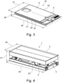
- the Fig.3 shows the Fig.2 in an assembled state shown front panels 5, 6, side panels 13, 14, 15, 16 and cover plate 19 before their assembly.
- the front panels 5, 6, the side panels 13, 14, 15, 16 and the cover plate 19 are packed as a panel set in a package 54 or in a (first) interior of the package 54.
- the front panels 5, 6, the side panels 13, 14, 15, 16 and the cover plate 19 are arranged on top of each other and parallel to each other in a first layer 21, second layer 22 and third layer 23.
- the first front panel 5 is in the first layer 21 and the second front panel 6 is in the third layer 23.
- the packaging 54 can be designed in the manner of a cuboid-shaped box.
- the packaging 54 or a first interior of the packaging 54 has a packaging length 56, a packaging width 57 and a packaging depth 58.
- the packaging 54, the front panels 5, 6, the side panels 13, 14, 15, 16 and the cover panel 19 form a panel packaging unit 55.
- the Fig.4 shows a packaging unit 1 with an outer packaging 2, which is designed here in the manner of a cuboid-shaped box.
- the outer packaging 2 or a (second) interior of the outer packaging 2 has an outer packaging length 59, an outer packaging width 60 and an outer packaging depth 61.
- the outer packaging 2 contains the installation element 3 with the mounting frame 4 and the plate packaging unit 55 with the Fig.2 shown front panels 5, 6, the side panels 13, 14, 15, 16 and the cover plate 19 are arranged on top of each other and/or parallel to each other.
- the present invention makes it possible to reduce the effort required for transporting and cutting the front panels 5, 6, the side panels 13, 14, 15, 16 and/or the cover panel 19.
Landscapes
- Engineering & Computer Science (AREA)
- Mechanical Engineering (AREA)
- Health & Medical Sciences (AREA)
- Life Sciences & Earth Sciences (AREA)
- Hydrology & Water Resources (AREA)
- Public Health (AREA)
- Water Supply & Treatment (AREA)
- Packaging Of Machine Parts And Wound Products (AREA)
Abstract
- eine Umverpackung (2);
- ein Installationselement (3), das einen Montagerahmen (4) umfasst, an dem ein Sanitärartikel befestigbar ist; und
- zumindest eine Frontplatte (5, 6) zum zumindest teilweisen Verkleiden einer Front (7) des Montagerahmens (4), wobei die zumindest eine Frontplatte (5, 6) eine Frontplattenbreite (8) aufweist, die maximal 50 mm von einer Rahmenbreite (9) des Montagerahmens (4) abweicht.
Description
- Die vorliegende Erfindung betrifft eine Verpackungseinheit mit einem Installationselement für einen Sanitärartikel. An dem Installationselement ist beispielsweise ein Sanitärartikel nach Art einer Toilette, eines Bidets und/oder eines Waschtischs befestigbar.
- Mit dem Installationselement ist der Sanitärartikel insbesondere an einer Wand eines Gebäudes befestigbar. Hierzu weist das Installationselement einen Montagerahmen auf, der an der Wand befestigbar ist. Der Montagerahmen wird mit zumindest einer Platte verkleidet, sodass dieser nach der Montage des Installationselements nicht mehr sichtbar ist. Auf der Platte können Verkleidungselemente, wie zum Beispiel Fliesen, befestigt werden. Die Platten sind großformatig und müssen bei der Installation des Installationselements zugeschnitten werden. Hierdurch sind die Platten schwer und aufwendig zu transportieren. Zudem ist das Zuschneiden der Platten aufwendig.
- Aufgabe der Erfindung ist es daher, die mit Bezug auf den Stand der Technik geschilderten Probleme zumindest teilweise zu lösen und insbesondere eine Verpackungseinheit anzugeben, durch die ein Aufwand für das Transportieren und Zuschneiden zumindest reduzierbar ist.
- Diese Aufgabe wird gelöst mit einer Verpackungseinheit gemäß den Merkmalen des unabhängigen Patentanspruchs. Weitere vorteilhafte Ausgestaltungen der Erfindung sind in den abhängigen Patentansprüchen angegeben. Es ist darauf hinzuweisen, dass die in den Patentansprüchen einzeln aufgeführten Merkmale in beliebiger technologisch sinnvoller Weise miteinander kombiniert werden können und weitere Ausgestaltungen der Erfindung definieren. Darüber hinaus werden die in den Patentansprüchen angegebenen Merkmale in der Beschreibung näher präzisiert und erläutert, wobei weitere bevorzugte Ausgestaltungen der Erfindung dargestellt werden.
- Hierzu trägt eine Verpackungseinheit bei, die zumindest Folgendes aufweist:
- eine Umverpackung;
- ein Installationselement, das einen Montagerahmen umfasst, an dem ein Sanitärartikel befestigbar ist; und
- zumindest eine Frontplatte zum zumindest teilweisen Verkleiden einer Front des Montagerahmens, wobei die zumindest eine Frontplatte eine Frontplattenbreite aufweist, die maximal 50 mm von einer Rahmenbreite des Montagerahmens abweicht.
- Bei der Verpackungseinheit handelt es sich insbesondere um eine Zusammenfassung mindestens eines Installationselements und zumindest einer Frontplatte in einer Umverpackung. Die Verpackungseinheit kann eine Verkaufseinheit bilden und/oder einer besseren Handhabung bzw. besseren Transportfähigkeit des Installationselements und/oder der zumindest einen Frontplatte dienen.
- Die Umverpackung kann zumindest teilweise quaderförmig und/oder nach Art eines Behälters, einer Kiste oder Kartons ausgebildet sein. Die Umverpackung kann zumindest teilweise aus Pappe, Wellpappe, Folie, Kunststoff, Holz und/oder Metall bestehen. Die Umverpackung kann das Installationselement und die zumindest eine Frontplatte zumindest teilweise oder vollständig umgeben. Das Installationselement und die zumindest eine Frontplatte können in der Umverpackung angeordnet sein. Die Umverpackung kann eine Umverpackungslänge von beispielsweise 1.008 mm bis 1.408 mm, bevorzugt 1.158 mm bis 1.208 mm, besonders bevorzugt (im Wesentlichen) 1.178 mm, (insbesondere orthogonal zu der Umverpackungslänge) eine Umverpackungsbreite von beispielsweise 416 mm bis 616 mm, bevorzugt 506 mm bis 556 mm, besonders bevorzugt (im Wesentlichen) 518 mm, (insbesondere orthogonal zu der Umverpackungslänge und/oder der Umverpackungsbreite) eine Umverpackungstiefe von beispielsweise 100 mm bis 400 mm und/oder eine Umverpackungsstärke von beispielsweise 1 mm bis 10 mm, bevorzugt 1 mm bis 5 mm, besonders bevorzugt (im Wesentlichen) 1,5 mm bis 2 mm, aufweisen.
- Das Installationselement dient der Befestigung eines, insbesondere wasserführenden, Sanitärartikels an einem Boden eines Gebäudes und/oder einer Wand des Gebäudes. Bei dem Sanitärartikel kann es sich beispielsweise um eine Toilette, ein Urinal, ein Dusche-WC, ein Bidet oder einen Waschtisch handeln.
- Das Installationselement weist einen Montagerahmen auf, an dem der Sanitärartikel befestigbar ist. Der Montagerahmen kann beispielsweise zumindest ein Metallprofil umfassen. Weiterhin kann der Montagerahmen beispielsweise ein (vertikales) erstes Metallprofil und ein (vertikales) zweites Metallprofil aufweisen, die über zumindest ein (horizontales) drittes Metallprofil und/oder zumindest eine (Metall-)Traverse miteinander verbunden sind. Das erste Metallprofil, das zweite Metallprofil und/oder das dritte Metallprofil können beispielsweise über eine Schweißverbindung oder Schraubverbindung miteinander verbunden sein. Alternativ können das erste Metallprofil, das zweite Metallprofil und/oder das dritte Metallprofil einstückig ausgebildet sein. Der Montagerahmen kann (insbesondere nach seiner (vertikalen) Befestigung an der Wand in einer horizontalen Richtung) eine Rahmenbreite von beispielsweise 400 mm [Millimeter] bis 600 mm, bevorzugt 490 mm bis 510 mm, besonders bevorzugt (im Wesentlichen) 500 mm, aufweisen. Der Montagerahmen kann höhenverstellbar sein. Dies kann bedeuten, dass (insbesondere in einer vertikalen Richtung) eine Rahmenhöhe des Montagerahmens einstellbar ist. Hierzu kann der Montagerahmen zumindest einen verstellbaren Fuß aufweisen. Beispielsweise kann der Montagerahmen einen an und/oder in dem (vertikalen) ersten Metallprofil verstellbaren ersten Fuß aufweisen. Beispielsweise kann der Montagerahmen einen an und/oder in dem (vertikalen) zweiten Metallprofil verstellbaren zweiten Fuß aufweisen. Die Rahmenhöhe kann beispielsweise 1.000 mm bis 1.400 mm, bevorzugt 1.130 mm bis 1.330 mm, betragen. Die Rahmenhöhe kann sich insbesondere nach der Montage des Installationselements bzw. des Montagerahmens an der Wand und/oder auf dem Boden) in der vertikalen Richtung bemessen.
- Der Montagerahmen kann an der Wand oder mit einem Abstand zu der Wand an der Wand befestigbar sein. Der Montagerahmen kann über zumindest ein Wandbefestigungselement an der Wand befestigbar sein. Der Abstand zur Wand kann beispielsweise 100 mm bis 400 mm, bevorzugt 135 mm bis 250 mm, besonders bevorzugt 135 mm bis 230 mm, betragen.
- Der Montagerahmen kann zumindest ein Befestigungselement für den Sanitärartikel aufweisen, das zum Beispiel nach Art einer Metallstange oder Gewindestange ausgebildet ist. Der Montagerahmen weist insbesondere eine Mehrzahl von Befestigungselementen für den Sanitärartikel auf, wobei die Befestigungselemente insbesondere mit Abstand zueinander und/oder auf gleicher Höhe angeordnet sein können. Das zumindest eine Befestigungselement kann insbesondere an der zumindest einer Traverse des Montagerahmens befestigt sein.
- Das Installationselement kann einen Spülkasten zur Aufnahme einer Spülflüssigkeit zum Spülen des Sanitärartikels umfassen. Der Spülkasten kann an dem Montagerahmen befestigt sein.
- Die Verpackungseinheit umfasst zumindest eine Frontplatte, mit der eine Front des Montagerahmens, insbesondere nach der Befestigung des Montagerahmens an der Wand, zumindest teilweise verkleidbar ist. Die Front des Montagerahmens weist nach der Montage des Installationselements insbesondere in Richtung des Sanitärartikels. Eine Rückseite des Montagerahmens weist nach der Montage des Installationselements insbesondere in Richtung der Wand. Die Front und die Rückseite des Montagerahmens können sich gegenüberliegen. Unter "verkleidbar" kann verstanden werden, dass die Front des Montagerahmens zumindest teilweise durch die zumindest eine Frontplatte abdeckbar ist, sodass der Montagerahmen nach der Installation des Installationselements an der Wand zumindest teilweise nicht mehr sichtbar ist. Die zumindest eine Frontplatte bzw. jede der Frontplatten können sich von dem (vertikalen) ersten Metallprofil bis zu dem (vertikalen) zweiten Metallprofil des Montagerahmens erstrecken. Die zumindest eine Frontplatte kann das (vertikale) erste Metallprofil und das (vertikale) zweite Metallprofil des Montagerahmens zumindest teilweise abdecken. Die zumindest eine Frontplatte kann (im Wesentlichen) rechteckförmig ausgebildet bzw. zugeschnitten sein. Die zumindest eine Frontplatte kann eine Plattenstärke bzw. Plattendicke von beispielsweise 10 mm bis 50 mm, bevorzugt 10 mm bis 30 mm, besonders bevorzugt (im Wesentlichen) 20 mm, aufweisen. Die Verpackungseinheit kann eine Mehrzahl von Frontplatten, beispielsweise eine erste Frontplatte und eine zweite Frontplatte, aufweisen. Die Mehrzahl von Frontplatten können miteinander durch Verbindungselemente, Nut-/Federsysteme, Einlegeformstücke und/oder Puzzeltechnik verbindbar sein. Die zumindest eine Frontplatte und/oder ein Kern der zumindest einen Frontplatte kann zumindest teilweise aus Gips, Gipsfaser, Gipskarton, Holz, Kunststoff, Hartschaum und/oder Schaumstoff bestehen. Bei dem Hartschaum kann es sich zum Beispiel um expandiertes Polystyrol (EPS) oder extrudiertes Polystyrol (XPS) handeln.
- Die zumindest eine Frontplatte kann auf einer Frontseite und/oder Rückseite mit einer Verstärkungsschicht verstärkt sein. Bei der Frontseite kann es sich um eine Außenseite der zumindest einen Frontplatte, eine nach außen orientierte Seite der zumindest einen Frontplatte, eine in Richtung des Sanitärartikels orientierte Seite der zumindest einen Frontplatte und/oder um eine Befestigungsfläche der zumindest einen Frontplatte für das zumindest eine Verkleidungselement handeln. Bei der Rückseite kann es sich um eine Innenseite der zumindest einen Frontplatte, eine nach innen gerichtete Seite der zumindest einen Frontplatte, eine in Richtung des Montagerahmens orientierte Seite der zumindest einen Frontplatte und/oder um eine Befestigungsfläche der zumindest einen Frontplatte für den Montagerahmen handeln. Die Verstärkungsschicht kann zumindest teilweise aus einem Glasfasergewebe, aus Mörtel, aus Zement, aus Kunstharz und/oder Kunststoff bestehen. Bei der Verstärkungsschicht kann es sich zumindest teilweise um eine Glasfasergewebe armierte Mörtelschicht handeln. Die Verstärkungsschicht kann auf der Frontseite und/oder der Rückseite eine Schichtdicke von beispielsweise 0,1 mm bis 5 mm, bevorzugt 1 mm bis 3 mm, besonders bevorzugt (im Wesentlichen) 2 mm, aufweisen. Die Verstärkungsschicht kann sich über eine gesamte Fläche der Frontseite der zumindest einen Frontplatte erstrecken. Die Verstärkungsschicht kann sich über eine gesamte Fläche der Rückseite der zumindest einen Frontplatte erstrecken.
- Die zumindest eine Frontplatte kann bzw. die Mehrzahl von Frontplatten können in einer Verpackung angeordnet sein. Die Verpackung kann zumindest teilweise quaderförmig und/oder nach Art eines Behälters, einer Kiste oder Kartons ausgebildet sein. Die Verpackung kann zumindest teilweise aus Pappe, Wellpappe, Folie, Kunststoff, Holz und/oder Metall bestehen. Die Verpackung kann die zumindest eine Frontplatte zumindest teilweise oder vollständig umgeben. Die zumindest eine Frontplatte kann in einem (ersten) Innenraum der Verpackung angeordnet sein. Die Verpackung kann eine Verpackungslänge von beispielsweise 908 mm bis 1.108 mm, bevorzugt 1.008 mm bis 1.058 mm, besonders bevorzugt (im Wesentlichen) 1.034 mm bis 1.038 mm, (insbesondere orthogonal zu der Verpackungslänge) eine Verpackungsbreite von beispielsweise 408 mm bis 608 mm, bevorzugt 498 mm bis 548 mm, besonders bevorzugt (im Wesentlichen) 508 mm bis 512 mm, (insbesondere orthogonal zu der Verpackungslänge und/oder der Verpackungsbreite) eine Verpackungstiefe von beispielsweise 38 mm bis 166 mm, bevorzugt 38 mm bis 98 mm, besonders bevorzugt (im Wesentlichen) 67 mm bis 71 mm, und/oder eine Verpackungsstärke von beispielsweise 1 mm bis 10 mm, bevorzugt 1 mm bis 5 mm, besonders bevorzugt (im Wesentlichen) 1,5 mm bis 2 mm, aufweisen. Die Verpackung mit der zumindest einen Frontplatte können als Plattenverpackungseinheit in der Umverpackung angeordnet sein.
- Die zumindest eine Frontplatte kann (insbesondere unmittelbar) an dem Montagerahmen bzw. an der Front des Montagerahmens befestigbar sein. Die Befestigung der zumindest einen Frontplatte kann beispielsweise mithilfe einer Klebeverbindung, einer Schraubverbindung, einer Steckverbindung, einer Schweißverbindung und/oder einer Klemmverbindung erfolgen. Auf einer Frontseite bzw. Außenseite der zumindest einen Frontplatte kann zumindest ein Verkleidungselement, beispielsweise nach Art einer Fliese, befestigbar sein. Die Befestigung des zumindest einen Verkleidungselements kann beispielsweise mithilfe einer Klebeverbindung erfolgen.
- Die zumindest eine Frontplatte weist eine Frontplattenbreite auf, die maximal 50 mm, bevorzugt maximal 40 mm, besonders bevorzugt maximal 5 mm, von der Rahmenbreite des Montagerahmens abweicht. Die Frontplattenbreite kann sich (insbesondere nach der Montage des Installationselements bzw. des Montagerahmens an der Wand und/oder auf dem Boden) in einer horizontalen Richtung und/oder in einer gleichen Richtung wie die Rahmenbreite des Montagerahmens bemessen. Insbesondere weist die Frontplatte eine Frontplattenbreite auf, die maximal 50 mm, bevorzugt maximal 40 mm, besonders bevorzugt maximal 5 mm, größer als die Rahmenbreite des Montagerahmens ist. Die Frontplattenbreite kann der Rahmenbreite des Montagerahmens zuzüglich der doppelten Plattenstärke bzw. Plattendicke (im Wesentlichen) entsprechend. Die Frontplattenbreite kann der Rahmenbreite des Montagerahmens (im Wesentlichen) entsprechen. Hierdurch ist die zumindest eine Frontplatte, beispielsweise als Zubehör, mit dem Installationselement in der Umverpackung anordenbar, insbesondere ohne dass eine Größe der Umverpackung (wesentlich) vergrößert werden muss. Zudem müssen Stellplätze und/oder Lagerplätze im Handel nicht an eine geänderte Größe der Umverpackung angepasst werden. Weiterhin ist die zumindest eine Frontplatte leichter handhabbar und/oder zuschneidbar.
- Die Frontplattenbreite kann 400 mm bis 600 mm betragen. Bevorzugt kann die Frontplattenbreite 490 mm bis 540 mm, besonders bevorzugt (im Wesentlichen) 500 mm, betragen.
- Die Verpackungseinheit kann eine erste Frontplatte und eine zweite Frontplatte aufweisen, durch die die gesamte Front des Montagerahmens verkleidbar ist. Dies kann beispielsweise bedeuten, dass die erste Frontplatte und die zweite Frontplatte derart zugeschnitten sind, dass durch diese gemeinsam die gesamte Front des Montagerahmens verkleidbar ist.
- Eine erste Frontplattenhöhe einer ersten Frontplatte und eine zweite Frontplattenhöhe einer zweiten Frontplatte können in Summe maximal 50 mm, bevorzugt maximal 40 mm, besonders bevorzugt maximal 5 mm, von einer Rahmenhöhe des Montagerahmens abweichen. Die Summe aus der ersten Frontplattenhöhe und der zweite Frontplattenhöhe kann (im Wesentlichen) der Rahmenhöhe des Montagerahmens entsprechen. Die erste Frontplattenhöhe und/oder zweite Frontplattenhöhe können sich (insbesondere nach der Montage des Installationselements bzw. des Montagerahmens an der Wand und/oder auf dem Boden) in der vertikalen Richtung und/oder in einer gleichen Richtung wie die Rahmenhöhe des Montagerahmens bemessen.
- Eine erste Frontplatte kann eine erste Frontplattenhöhe von 300 mm bis 500 mm, bevorzugt 350 mm bis 400 mm, besonders bevorzugt (im Wesentlichen) 370 mm aufweisen.
- Eine zweite Frontplatte kann eine zweite Frontplattenhöhe von 700 bis 900 mm, bevorzugt 780 mm bis 820 mm, besonders bevorzugt (im Wesentlichen) 800 mm aufweisen.
- Eine erste Frontplattenhöhe einer ersten Frontplatte und eine zweite Frontplattenhöhe einer zweiten Frontplatte können in Summe 1.000 mm bis 1.400 mm, bevorzugt 1.130 mm bis 1.330 mm, besonders bevorzugt (im Wesentlichen) 1.170 mm, betragen.
- Die Verpackungseinheit kann zumindest eine Seitenplatte zum zumindest teilweisen Verkleiden zumindest einer Seite des Montagerahmens aufweisen. Die zumindest eine Seite des Montagerahmens ist mit der zumindest einen Seitenplatte, insbesondere nach der Befestigung des Montagerahmens an der Wand, zumindest teilweise verkleidbar. Bei der zumindest einen Seite kann es sich um eine rechte Seite und/oder linke Seite des Montagerahmens handeln. Die linke Seite und die rechte Seite des Montagerahmens können sich gegenüberliegen. Die zumindest eine Seite kann orthogonal zu der Front des Montagerahmens verlaufen. Unter "verkleidbar" kann verstanden werden, dass die zumindest eine Seite des Montagerahmens zumindest teilweise durch die zumindest eine Seitenplatte abdeckbar ist, sodass der Montagerahmen nach der Installation des Installationselements an der Wand zumindest teilweise nicht mehr sichtbar ist. Die zumindest eine Seitenplatte bzw. jede der Seitenplatten können sich zumindest teilweise entlang des (vertikalen) ersten Metallprofils oder entlang des (vertikalen) zweiten Metallprofils des Montagerahmens erstrecken. Die zumindest eine Seitenplatte kann das (vertikale) erste Metallprofil und/oder das (vertikale) zweite Metallprofil des Montagerahmens zumindest teilweise abdecken. Die zumindest eine Seitenplatte kann (im Wesentlichen) rechteckförmig ausgebildet bzw. zugeschnitten sein. Die zumindest eine Seitenplatte kann eine Plattenstärke bzw. Plattendicke von beispielsweise 10 mm bis 50 mm, bevorzugt 10 mm bis 30 mm, besonders bevorzugt (im Wesentlichen) 20 mm, aufweisen. Die Verpackungseinheit kann eine Mehrzahl von Seitenplatten, beispielsweise eine erste Seitenplatte, zweite Seitenplatte, dritte Seitenplatte und vierte Seitenplatte, aufweisen. Die Mehrzahl von Seitenplatten können miteinander durch die Verbindungselemente, Nut-/Federsysteme, Einlegeformstücke und/oder Puzzeltechnik verbindbar sein. Die zumindest eine Seitenplatte und/oder ein Kern der zumindest einen Seitenplatte kann zumindest teilweise aus Gips, Gipsfaser, Gipskarton, Holz, Kunststoff, Hartschaum und/oder Schaumstoff bestehen. Bei dem Hartschaum kann es sich zum Beispiel um expandiertes Polystyrol (EPS) oder extrudiertes Polystyrol (XPS) handeln.
- Die zumindest eine Seitenplatte kann auf einer Frontseite und/oder Rückseite mit der Verstärkungsschicht verstärkt sein. Bei der Frontseite kann es sich um eine Außenseite der zumindest einen Seitenplatte, eine nach außen orientierte Seite der zumindest einen Seitenplatte und/oder um eine Befestigungsfläche der zumindest einen Seitenplatte für das zumindest eine Verkleidungselement handeln. Bei der Rückseite kann es sich um eine Innenseite der zumindest einen Seitenplatte, eine nach innen gerichtete Seite der zumindest einen Seitenplatte, eine in Richtung des Montagerahmens orientierte Seite der zumindest einen Seitenplatte und/oder um eine Befestigungsfläche der zumindest einen Seitenplatten für den Montagerahmen handeln. Die Verstärkungsschicht kann sich über eine gesamte Fläche der Frontseite der zumindest einen Seitenplatte erstrecken. Die Verstärkungsschicht kann sich über eine gesamte Fläche der Rückseite der zumindest einen Seitenplatte erstrecken.
- Die zumindest eine Seitenplatte kann bzw. die Mehrzahl von Seitenplatten können in der Verpackung angeordnet sein. Die zumindest eine Seitenplatte kann in dem (ersten) Innenraum der Verpackung angeordnet sein. Die Verpackung mit der zumindest einen Frontplatte und der zumindest einen Seitenplatte können als Plattenverpackungseinheit in der Umverpackung angeordnet sein.
- Die zumindest eine Seitenplatte kann (insbesondere unmittelbar) an dem Montagerahmen bzw. an der zumindest einen Seite des Montagerahmens befestigbar sein. Die Befestigung der zumindest einen Seitenplatte kann beispielsweise mithilfe einer Klebeverbindung, einer Schraubverbindung, einer Steckverbindung, einer Schweißverbindung und/oder einer Klemmverbindung erfolgen. Auf einer Frontseite bzw. Außenseite der zumindest einen Seitenplatte kann zumindest ein Verkleidungselement befestigbar sein. Die Befestigung des zumindest einen Verkleidungselements kann beispielsweise mithilfe einer Klebeverbindung erfolgen.
- Die zumindest eine Seitenplatte bzw. jede der Seitenplatten kann (im Wesentlichen) rechteckförmig ausgebildet bzw. zugeschnitten sein. Die zumindest eine Seitenplatte bzw. jede der Seitenplatten kann eine Seitenplattenbreite von beispielsweise 50 mm bis 400 mm aufweisen. Bevorzugt kann die Seitenplattenbreite 200 mm bis 300 mm, besonders bevorzugt (im Wesentlichen) 250 mm, betragen. Die Seitenplattenbreite kann sich (insbesondere nach der Montage des Installationselements bzw. des Montagerahmens an der Wand und/oder auf dem Boden) in der horizontalen Richtung und/oder orthogonal zu der Wand bemessen. Die zumindest eine Seitenplatte bzw. jede der Seitenplatten kann eine Seitenplattenhöhe von beispielsweise 510 mm bis 710 mm, bevorzugt 575 mm bis 620 mm, besonders bevorzugt (im Wesentlichen) 595 mm, aufweisen. Die Seitenplattenhöhe kann sich (insbesondere nach der Montage des Installationselements bzw. des Montagerahmens an der Wand und/oder auf dem Boden) in der vertikalen Richtung und/oder in der gleichen Richtung wie die Rahmenhöhe des Montagerahmens bemessen. Alle Seitenplatten können die gleiche Seitenplattenbreite und/oder die gleiche Seitenplattenhöhe aufweisen. Alle Seitenplatten können (im Wesentlichen) identisch ausgebildet sein.
- Mit der ersten Seitenplatte und der zweiten Seitenplatte kann mindestens die gesamte linke Seite des Montagerahmens und/oder mit der dritten Seitenplatte und der vierten Seitenplatte mindestens die gesamte rechte Seite des Montagerahmens verkleidbar sein. Die erste Seitenplatte und die zweite Seitenplatte können derart zugeschnitten sein, dass durch diese gemeinsam die gesamte linke Seite des Montagerahmens verkleidbar ist. Die dritte Seitenplatte und die vierte Seitenplatte können derart zugeschnitten sein, dass durch diese gemeinsam die gesamte rechte Seite des Montagerahmens verkleidbar ist.
- Die Verpackungseinheit kann zumindest eine Deckplatte zum zumindest teilweisen verkleiden einer Oberseite des Montagerahmens aufweisen. Die Oberseite des Montagerahmens ist mit der zumindest einen Deckplatte insbesondere nach der Befestigung des Montagerahmens an der Wand zumindest teilweise oder vollständig verkleidbar. Die Oberseite kann (im Wesentlichen) horizontal verlaufen. Unter "verkleidbar" kann verstanden werden, dass die Oberseite des Montagerahmens zumindest teilweise durch die zumindest eine Deckplatte abdeckbar ist, sodass der Montagerahmen nach der Installation des Installationselements an der Wand zumindest teilweise nicht mehr sichtbar ist. Die zumindest eine Deckplatte bzw. jede der Deckplatten können sich zumindest teilweise entlang des (horizontalen) dritten Metallprofils des Montagerahmens erstrecken. Die zumindest eine Deckplatte kann das (horizontale) dritten Metallprofil des Montagerahmens zumindest teilweise abdecken. Die zumindest eine Deckplatte kann (im Wesentlichen) rechteckförmig ausgebildet bzw. zugeschnitten sein. Die zumindest eine Deckplatte kann eine Plattenstärke bzw. Plattendicke von beispielsweise 10 mm bis 50 mm, bevorzugt 10 mm bis 30 mm, besonders bevorzugt (im Wesentlichen) 20 mm, aufweisen. Die Verpackungseinheit kann eine einzige Deckplatte oder eine Mehrzahl von Deckplatten aufweisen. Die Mehrzahl von Deckplatten können miteinander durch die Verbindungselemente, Nut-/Federsysteme, Einlegeformstücke und/oder Puzzeltechnik verbindbar sein. Die zumindest eine Deckplatte und/oder ein Kern der zumindest einen Deckplatte kann zumindest teilweise aus Gips, Gipsfaser, Gipskarton, Holz, Kunststoff, Hartschaum und/oder Schaumstoff bestehen. Bei dem Hartschaum kann es sich zum Beispiel um expandiertes Polystyrol (EPS) oder extrudiertes Polystyrol (XPS) handeln.
- Die zumindest eine Deckplatte kann auf einer Frontseite und/oder Rückseite mit der Verstärkungsschicht verstärkt sein. Bei der Frontseite kann es sich um eine Außenseite der zumindest einen Deckplatte, eine nach außen orientierte Seite der zumindest einen Deckplatte und/oder um eine Befestigungsfläche der zumindest einen Deckplatte für das zumindest eine Verkleidungselement handeln. Bei der Rückseite kann es sich um eine Innenseite der zumindest einen Deckplatte, eine nach innen gerichtete Seite der zumindest einen Deckplatte, eine in Richtung des Montagerahmens orientierte Seite der zumindest einen Deckplatte und/oder um eine Befestigungsfläche der zumindest einen Deckplatte für den Montagerahmen handeln. Die Verstärkungsschicht kann sich über eine gesamte Fläche der Frontseite der zumindest einen Deckplatte erstrecken. Die Verstärkungsschicht kann sich über eine gesamte Fläche der Rückseite der zumindest einen Deckplatte erstrecken.
- Die zumindest eine Deckplatte kann bzw. die Mehrzahl von Deckplatten können in der Verpackung angeordnet sein. Die zumindest eine Deckplatte kann in dem (ersten) Innenraum der Verpackung angeordnet sein. Die Verpackung mit der zumindest einen Frontplatte, der zumindest einen Seitenplatte und der zumindest einen Deckplatte können als Plattenverpackungseinheit in der Umverpackung angeordnet sein.
- Die zumindest eine Deckplatte kann (insbesondere unmittelbar) an dem Montagerahmen bzw. an der Oberseite des Montagerahmens befestigbar sein. Die Befestigung der zumindest einen Deckplatte kann beispielsweise mithilfe einer Klebeverbindung, einer Schraubverbindung, einer Steckverbindung, einer Schweißverbindung und/oder einer Klemmverbindung erfolgen. Auf einer Frontseite bzw. Außenseite der zumindest einen Deckplatte kann zumindest ein Verkleidungselement befestigbar sein. Die Befestigung des zumindest einen Verkleidungselements kann beispielsweise mithilfe einer Klebeverbindung erfolgen.
- Die zumindest eine Deckplatte kann (im Wesentlichen) rechteckförmig ausgebildet bzw. zugeschnitten sein. Die zumindest eine Deckplatte kann eine Deckplattenbreite von beispielsweise 50 mm bis 400 mm aufweisen. Bevorzugt kann die Deckplattenbreite 200 mm bis 300 mm, besonders bevorzugt (im Wesentlichen) 250 mm, betragen. Die Deckplattenbreite kann sich (insbesondere nach der Montage des Installationselements bzw. des Montagerahmens an der Wand und/oder auf dem Boden) in der horizontalen Richtung und/oder orthogonal zu der Wand bemessen. Die zumindest eine Deckplatte kann eine Deckplattenlänge von beispielsweise 400 mm bis 600 mm, bevorzugt 490 mm bis 540 mm, besonders bevorzugt (im Wesentlichen) 500 mm, betragen. Die Deckplattenlänge kann der Frontplattenbreite der zumindest einen Frontplatte und/oder der Rahmenbreite des Montagerahmens entsprechen. Die Deckplattenlänge kann sich (insbesondere nach der Montage des Installationselements bzw. des Montagerahmens an der Wand und/oder auf dem Boden) in der horizontalen Richtung, in der gleichen Richtung wie die Frontplattenbreite und/oder in der gleichen Richtung wie die Rahmenbreite des Montagerahmens bemessen.
- Die zumindest eine Frontplatte, die zumindest eine Seitenplatte und die zumindest eine Deckplatte können in maximal drei Lagen aufeinander angeordnet sein. Dies kann insbesondere bedeuten, dass nicht mehr als drei Frontplatten, Seitenplatten und/oder Deckplatten aufeinander angeordnet sind. Die zumindest eine Frontplatte, die zumindest eine Seitenplatte und die zumindest eine Deckplatte können in den Lagen unmittelbar aufeinander und/oder parallel zueinander angeordnet sein.
- Die Erfindung sowie das technische Umfeld werden nachfolgend anhand der Figuren näher erläutert. Es ist darauf hinzuweisen, dass die Figuren eine bevorzugte Ausführungsvariante der Erfindung zeigen, diese jedoch nicht darauf beschränkt ist. Dabei sind gleiche Bauteile in den Figuren mit denselben Bezugszeichen versehen. Es zeigen beispielhaft und schematisch:
- Fig. 1:
- ein Installationselement mit einem Montagerahmen;
- Fig. 2:
- das Installationselement in einem verkleideten Zustand;
- Fig. 3:
- ein in einer Verpackung angeordnetes Plattenset; und
- Fig. 4:
- eine Verpackungseinheit mit dem Installationselement und dem Plattenset.
- Die
Fig. 1 zeigt ein Installationselement 3 mit einem Montagerahmen 4, der an einem Boden 24 und einer Wand 25 eines Gebäudes befestigt ist. An dem Montagerahmen 4 ist ein Spülkasten 26 zur Aufnahme einer Spülflüssigkeit befestigt, die einem hier nicht gezeigten Sanitärartikel über eine Zuführleitung 27 zuführbar ist. Nach dem Spülen des Sanitärartikels ist das Spülwasser über eine Abflussleitung 28 einem hier nicht gezeigten Abwasserkanal zuführbar. Weiterhin weist der Montagerahmen 4 ein erstes Befestigungselement 29 und ein zweites Befestigungselement 30 auf, an denen der Sanitärartikel befestigbar ist und die hier nach Art von Gewindestangen ausgebildet sind. Die Befestigungselemente 29, 30 sind an einer ersten Traverse 31 des Montagerahmens 4 befestigt, die sich (horizontal) von einem (vertikalen) ersten Metallprofil 32 zu einem (vertikalen) zweiten Metallprofil 33 des Montagerahmens 4 erstreckt. Der Montagerahmen 4 weist eine zweite Traverse 34 auf, die sich ebenfalls horizontal von dem ersten Metallprofil 32 zu dem zweiten Metallprofil 33 erstreckt. Die erste Traverse 31 ist oberhalb der Abflussleitung 28 und die zweite Traverse 34 unterhalb der Abflussleitung 28 angeordnet. Der Montagerahmen 4 weist (in einer horizontalen Richtung) eine Rahmenbreite 9 und (in einer vertikalen Richtung und/oder orthogonal zu der Rahmenbreite 9) eine Rahmenhöhe 12 auf. - Die
Fig. 2 zeigt das Installationselement 3 nach seiner Verkleidung mit einer ersten Frontplatte 5, zweiten Frontplatte 6, ersten Seitenplatte 13, zweiten Seitenplatte 14, dritten Seitenplatte 15, vierten Seitenplatte 16 und einer Deckplatte 19. Die erste Frontplatte 5 weist (in der vertikalen Richtung) eine erste Frontplattenhöhe 10 und die zweite Frontplatte 6 (in der vertikalen Richtung) eine zweite Frontplattenhöhe 11 auf. Die erste Frontplattenhöhe 10 und die zweite Frontplattenhöhe 11 entsprechen in Summe der in derFig. 1 gezeigten Rahmenhöhe 12. Die erste Frontplatte 5 und die zweite Frontplatte 6 weisen (in der horizontalen Richtung) eine gleiche Frontplattenbreite 8 auf, die der in derFig. 1 gezeigten Rahmenbreite 9 entspricht. Die erste Frontplatte 5 und die zweite Frontplatte 6 verkleiden eine gesamte in derFig. 1 gezeigte Front 7 des Montagerahmens 4. Die erste Frontplatte 5 und die zweite Frontplatte 6 bilden eine erste Fuge 35 bzw. einen Stoß. Die erste Fuge 35 bzw. der Stoß verlaufen in der horizontalen Richtung auf Höhe der in derFig. 1 gezeigten ersten Traverse 31. Die erste Frontplatte 5 und die zweite Frontplatte 6 schließen bündig miteinander ab. Insbesondere fluchten eine erste Frontseite 49 der ersten Frontplatte 5 und eine zweite Frontseite 47 der zweiten Frontplatte 6 miteinander. Die erste Frontplatte 5 weist eine erste Öffnung 38 für die Abflussleitung 28 auf. Die zweite Frontplatte 6 weist eine zweite Öffnung 39 für die Zuführleitung 27 und eine dritte Öffnung 40 als Revisionsöffnung für den in derFig. 1 gezeigten Spülkasten 26 auf. - Die Deckplatte 19 weist (in der horizontalen Richtung) eine Deckplattenlänge 45 und (in der horizontalen Richtung und/oder orthogonal zu der Deckplattenlänge 45) eine Deckplattenbreite 46 auf. Die Deckplattenlänge 45 entspricht der Frontplattenbreite 8 und der in der
Fig. 1 gezeigten Rahmenbreite 9. Die Deckplatte 19 erstreckt sich in einer horizontalen Ebene und verkleidet eine in derFig. 1 gezeigte Oberseite 20 des Montagerahmens 4 (vollständig). Die Deckplatte 19 schließt bündig mit der zweiten Frontseite 47 der zweiten Frontplatte 6 ab. - Die erste Seitenplatte 13 weist (in der vertikalen Richtung) eine erste Seitenplattenhöhe 41, die zweite Seitenplatte 14 eine zweite Seitenplattenhöhe 42, die dritte Seitenplatte 15 eine dritte Seitenplattenhöhe 43 und die vierte Seitenplatte 16 eine vierte Seitenplattenhöhe 44 auf. Die Seitenplattenhöhen 41, 42, 43, 44 sind gleich. Die zweite Seitenplatte 14 und die vierte Seitenplatte 16 schließen bündig mit einer Oberseite 50 der Deckplatte 19 ab. Die Seitenplattenhöhen 13, 14, 15, 16 weisen (in der horizontalen Richtung und/oder orthogonal zu den Seitenplattenhöhen 41, 42, 43, 44) jeweils eine Seitenplattenbreite 48 auf. Die Seitenplatten 13, 14, 15, 16 schließen bündig mit den Frontseiten 47, 49 der Frontplatten 5, 6 ab. Die erste Seitenplatte 13 und die zweite Seitenplatte 14 verkleiden (vollständig) eine in der
Fig. 1 gezeigte linke Seite 17 des Montagerahmens 4 und die dritte Seitenplatte 15 und vierte Seitenplatte 16 (vollständig) eine in derFig. 1 gezeigte rechte Seite 18 des Montagerahmens 4. Die erste Seitenplatte 13 und die zweite Seitenplatte 14 bilden eine (horizontal verlaufende) zweite Fuge 36. Die dritte Seitenplatte 15 und die vierte Seitenplatte 16 bilden eine (horizontal verlaufende) dritte Fuge 37. Die Frontplatten 5, 6, die Seitenplatten 13, 14, 15, 16 und die Deckplatte 19 weisen eine (gleiche) Plattenstärke 51 auf. Eine Gesamthöhe 52 der ersten Seitenplatte 13 und zweiten Seitenplatte 14 oder der dritten Seitenplatte 15 und vierten Seitenplatte 16 entspricht daher der in derFig. 1 gezeigten Rahmenhöhe 12 zuzüglich der Plattenstärke 51 (der Deckplatte 19). Eine Gesamtbreite 53 der aus den Frontplatten 5, 6, den Seitenplatten 13, 14, 15, 16 und der Deckplatte 19 gebildeten Verkleidung des in derFig. 1 gezeigten Montagerahmens 4 entspricht der Rahmenbreite 9 zuzüglich der doppelten Plattenstärke 51. - Die
Fig. 3 zeigt die in derFig. 2 in einem montierten Zustand gezeigten Frontplatten 5, 6, Seitenplatten 13, 14, 15, 16 und Deckplatte 19 vor ihrer Montage. Die Frontplatten 5, 6, die Seitenplatten 13, 14, 15, 16 und die Deckplatte 19 sind als Plattenset in einer Verpackung 54 bzw. in einem (ersten) Innenraum der Verpackung 54 verpackt. Die Frontplatten 5, 6, die Seitenplatten 13, 14, 15, 16 und die Deckplatte 19 sind in einer ersten Lage 21, zweiten Lage 22 und dritten Lage 23 aufeinander und parallel zueinander angeordnet. In dem in derFig. 3 gezeigten Beispiel befindet sich die erste Frontplatte 5 in der ersten Lage 21 und die zweite Frontplatte 6 in der dritten Lage 23. Die Verpackung 54 kann nach Art eines quaderförmigen Kartons ausgebildet sein. Die Verpackung 54 bzw. ein erster Innenraum der Verpackung 54 weist eine Verpackungslänge 56, eine Verpackungsbreite 57 und eine Verpackungstiefe 58 auf. Die Verpackung 54, die Frontplatten 5, 6, die Seitenplatten 13, 14, 15, 16 und die Deckplatte 19 bilden eine Plattenverpackungseinheit 55. - Die
Fig. 4 zeigt eine Verpackungseinheit 1 mit einer Umverpackung 2, die hier nach Art eines quaderförmigen Kartons ausgebildet ist. Die Umverpackung 2 bzw. ein (zweiter) Innenraum der Umverpackung 2 weist eine Umverpackungslänge 59, eine Umverpackungsbreite 60 und eine Umverpackungstiefe 61 auf. In der Umverpackung 2 sind das Installationselement 3 mit dem Montagerahmen 4 und die Plattenverpackungseinheit 55 mit den in derFig. 2 gezeigten Frontplatten 5, 6, den Seitenplatten 13, 14, 15, 16 und der Deckplatte 19 aufeinander und/oder parallel zueinander angeordnet. - Durch die vorliegende Erfindung ist ein Aufwand für das Transportieren und Zuschneiden der Frontplatten 5, 6, der Seitenplatten 13, 14, 15, 16 und/oder der Deckplatte 19 reduzierbar.
-
- 1
- Verpackungseinheit
- 2
- Umverpackung
- 3
- Installationselement
- 4
- Montagerahmen
- 5
- erste Frontplatte
- 6
- zweite Frontplatte
- 7
- Front
- 8
- Frontplattenbreite
- 9
- Rahmenbreite
- 10
- erste Frontplattenhöhe
- 11
- zweite Frontplattenhöhe
- 12
- Rahmenhöhe
- 13
- erste Seitenplatte
- 14
- zweite Seitenplatte
- 15
- dritte Seitenplatte
- 16
- vierte Seitenplatte
- 17
- linke Seite
- 18
- rechte Seite
- 19
- Deckplatte
- 20
- Oberseite
- 21
- erste Lage
- 22
- zweite Lage
- 23
- dritte Lage
- 24
- Boden
- 25
- Wand
- 26
- Spülkasten
- 27
- Zuführleitung
- 28
- Abflussleitung
- 29
- erstes Befestigungselement
- 30
- zweites Befestigungselement
- 31
- erste Traverse
- 32
- erstes Metallprofil
- 33
- zweites Metallprofil
- 34
- zweite Traverse
- 35
- erste Fuge
- 36
- zweite Fuge
- 37
- dritte Fuge
- 38
- erste Öffnung
- 39
- zweite Öffnung
- 40
- dritte Öffnung
- 41
- erste Seitenplattenhöhe
- 42
- zweite Seitenplattenhöhe
- 43
- dritte Seitenplattenhöhe
- 44
- vierte Seitenplattenhöhe
- 45
- Deckplattenlänge
- 46
- Deckplattenbreite
- 47
- zweite Frontseite
- 48
- Seitenplattenbreite
- 49
- erste Frontseite
- 50
- Oberseite
- 51
- Plattenstärke
- 52
- Gesamthöhe
- 53
- Gesamtbreite
- 54
- Verpackung
- 55
- Plattenverpackungseinheit
- 56
- Verpackungslänge
- 57
- Verpackungsbreite
- 58
- Verpackungstiefe
- 59
- Umverpackungslänge
- 60
- Umverpackungsbreite
- 61
- Umverpackungstiefe
Claims (10)
- Verpackungseinheit (1), zumindest aufweisend:- eine Umverpackung (2);- ein Installationselement (3), das einen Montagerahmen (4) umfasst, an dem ein Sanitärartikel befestigbar ist; und- zumindest eine Frontplatte (5, 6) zum zumindest teilweisen Verkleiden einer Front (7) des Montagerahmens (4), wobei die zumindest eine Frontplatte (5, 6) eine Frontplattenbreite (8) aufweist, die maximal 50 mm von einer Rahmenbreite (9) des Montagerahmens (4) abweicht.
- Verpackungseinheit (1) nach Patentanspruch 1, wobei die Frontplattenbreite (8) 400 mm bis 600 mm beträgt.
- Verpackungseinheit (1) nach Patentanspruch 1, aufweisend eine erste Frontplatte (5) und eine zweite Frontplatte (6), durch die die gesamte Front (7) des Montagerahmens (4) verkleidbar ist.
- Verpackungseinheit (1) nach einem der vorhergehenden Patentansprüche, wobei eine erste Frontplattenhöhe (10) einer ersten Frontplatte (5) und eine zweite Frontplattenhöhe (11) einer zweiten Frontplatte (6) in Summe maximal 50 mm von einer Rahmenhöhe (12) des Montagerahmens (4) abweichen.
- Verpackungseinheit (1) nach einem der vorhergehenden Patentansprüche, wobei eine erste Frontplatte (5) eine erste Frontplattenhöhe (10) von 300 mm bis 500 mm aufweist.
- Verpackungseinheit (1) nach einem der vorhergehenden Patentansprüche, wobei eine zweite Frontplatte (6) eine zweite Frontplattenhöhe (11) von 700 mm bis 900 mm aufweist.
- Verpackungseinheit (1) nach einem der vorhergehenden Patentansprüche, wobei eine erste Frontplattenhöhe (10) einer ersten Frontplatte (5) und eine zweite Frontplattenhöhe (11) einer zweiten Frontplatte (6) in Summe 1.000 mm bis 1.400 mm betragen.
- Verpackungseinheit (1), aufweisend zumindest eine Seitenplatte (13, 14, 15, 16) zum zumindest teilweisen Verkleiden zumindest einer Seite (17, 18) des Montagerahmens (4).
- Verpackungseinheit (1), aufweisend zumindest eine Deckplatte (19) zum zumindest teilweisen Verkleiden einer Oberseite (20) des Montagerahmens (4).
- Verpackungseinheit (1) nach Patentanspruch 8 und 9, wobei die zumindest eine Frontplatte (5, 6), die zumindest eine Seitenplatte (13, 14, 15, 16) und die zumindest eine Deckplatte (19) in maximal drei Lagen (21, 22, 23) aufeinander angeordnet sind.
Applications Claiming Priority (1)
| Application Number | Priority Date | Filing Date | Title |
|---|---|---|---|
| DE102022127267.2A DE102022127267A1 (de) | 2022-10-18 | 2022-10-18 | Verpackungseinheit mit einem Installationselement für einen Sanitärartikel |
Publications (1)
| Publication Number | Publication Date |
|---|---|
| EP4357269A1 true EP4357269A1 (de) | 2024-04-24 |
Family
ID=88690084
Family Applications (1)
| Application Number | Title | Priority Date | Filing Date |
|---|---|---|---|
| EP23204495.8A Pending EP4357269A1 (de) | 2022-10-18 | 2023-10-18 | Verpackungseinheit mit einem installationselement für einen sanitaerartikel |
Country Status (2)
| Country | Link |
|---|---|
| EP (1) | EP4357269A1 (de) |
| DE (1) | DE102022127267A1 (de) |
Citations (3)
| Publication number | Priority date | Publication date | Assignee | Title |
|---|---|---|---|---|
| EP1916346A1 (de) * | 2006-10-20 | 2008-04-30 | Geberit Technik Ag | Verkleidung für eine sanitäre Installationseinrichtung, Installationseinrichtung mit einer solchen Verkleidung und Verfahren zum Montieren einer Installationseinrichtung mit einer solchen Verkleidung |
| JP2016003014A (ja) * | 2014-06-13 | 2016-01-12 | 株式会社Lixil | キャビネット付き便器における付属部品の梱包構造 |
| WO2022113067A1 (en) * | 2020-11-26 | 2022-06-02 | Zion Reuven | Wall for tiling |
Family Cites Families (1)
| Publication number | Priority date | Publication date | Assignee | Title |
|---|---|---|---|---|
| JP2008163014A (ja) * | 2006-12-06 | 2008-07-17 | Kaneka Corp | 11βHSD1阻害剤及びその用途 |
-
2022
- 2022-10-18 DE DE102022127267.2A patent/DE102022127267A1/de active Pending
-
2023
- 2023-10-18 EP EP23204495.8A patent/EP4357269A1/de active Pending
Patent Citations (3)
| Publication number | Priority date | Publication date | Assignee | Title |
|---|---|---|---|---|
| EP1916346A1 (de) * | 2006-10-20 | 2008-04-30 | Geberit Technik Ag | Verkleidung für eine sanitäre Installationseinrichtung, Installationseinrichtung mit einer solchen Verkleidung und Verfahren zum Montieren einer Installationseinrichtung mit einer solchen Verkleidung |
| JP2016003014A (ja) * | 2014-06-13 | 2016-01-12 | 株式会社Lixil | キャビネット付き便器における付属部品の梱包構造 |
| WO2022113067A1 (en) * | 2020-11-26 | 2022-06-02 | Zion Reuven | Wall for tiling |
Also Published As
| Publication number | Publication date |
|---|---|
| DE102022127267A1 (de) | 2024-04-18 |
Similar Documents
| Publication | Publication Date | Title |
|---|---|---|
| DE69128482T2 (de) | Plattenmodul aus geschäumtem kunststoff mit versetzten t-förmigen längskanälen für hölzerne stützen | |
| DE3016963A1 (de) | Einsetz-baustein fuer gebaeudewaende und verfahren zum konstruieren von gebaeuden unter verwendung derartiger bausteine | |
| WO2019166039A1 (de) | Modul und verfahren zum herstellen eines moduls, einer gebäudewand und eines gebäudes | |
| DE102020120983A1 (de) | Raumteil-Modul, insbesondere Gewerbe-Modul daraus hergestelltes Gebäude, sowie jeweils ein Herstellverfahren hierfür | |
| DE2706888A1 (de) | Form zur herstellung von beton- decken und -daechern | |
| EP0751262B1 (de) | Wandelement für Hochbauten und Verfahren zu seiner Herstellung | |
| DE102022127267A1 (de) | Verpackungseinheit mit einem Installationselement für einen Sanitärartikel | |
| CH670472A5 (de) | ||
| DE202010003519U1 (de) | Wandmodul, Wandaufhängung, Wandsystem und Innenraum | |
| DE2020607B2 (de) | Mehrstöckiges Gebäude aus einheitlichen, vorgefertigten Raumzellen | |
| DE3309820A1 (de) | Deckenplatte und verfahren zu ihrer herstellung | |
| DE19643800C2 (de) | Wandschalung | |
| DE19640633A1 (de) | Verfahren zur Befestigung von Strukturelementen, entsprechendes Strukturelement und Halteelement hierfür | |
| EP2479359B1 (de) | Schallschutzelement und Verfahren zum Fertigen eines Schallschutzelementes | |
| DE102017120254B4 (de) | Winkelelement und Laibungsverkleidung mit einem Winkelelement | |
| AT18173U1 (de) | Schwimmbecken | |
| DE102008059364B4 (de) | Gebäude-Schalldämmmatte | |
| EP0808238B1 (de) | Verfahren zur herstellung von wärmeisolierten tafeln für die grosstafelbauweise | |
| DE102017114619B4 (de) | System aus zumindest zwei Transporthaken und einem vorgefertigten Wandelement und Verfahren zur Herstellung eines vorgefertigten Wandelements | |
| DE2310299A1 (de) | Verfahren und drahtbuegel bzw. -anker zur herstellung von mantelbetonwaenden | |
| DE29512485U1 (de) | Rohrverkleidung | |
| DE2062344A1 (de) | Tragelement fur Wandplatten | |
| DE10252649A1 (de) | Randdämmstreifen | |
| DE202017007193U1 (de) | Vorgefertigtes Wandelement | |
| DE102022121744A1 (de) | Installationselement für einen Sanitärartikel |
Legal Events
| Date | Code | Title | Description |
|---|---|---|---|
| PUAI | Public reference made under article 153(3) epc to a published international application that has entered the european phase |
Free format text: ORIGINAL CODE: 0009012 |
|
| STAA | Information on the status of an ep patent application or granted ep patent |
Free format text: STATUS: THE APPLICATION HAS BEEN PUBLISHED |
|
| AK | Designated contracting states |
Kind code of ref document: A1 Designated state(s): AL AT BE BG CH CY CZ DE DK EE ES FI FR GB GR HR HU IE IS IT LI LT LU LV MC ME MK MT NL NO PL PT RO RS SE SI SK SM TR |
|
| STAA | Information on the status of an ep patent application or granted ep patent |
Free format text: STATUS: REQUEST FOR EXAMINATION WAS MADE |
|
| 17P | Request for examination filed |
Effective date: 20241015 |
|
| RBV | Designated contracting states (corrected) |
Designated state(s): AL AT BE BG CH CY CZ DE DK EE ES FI FR GB GR HR HU IE IS IT LI LT LU LV MC ME MK MT NL NO PL PT RO RS SE SI SK SM TR |