EP4351941B1 - Bremsanlage eines kraftfahrzeugs und verfahren zur steuerung derselben - Google Patents
Bremsanlage eines kraftfahrzeugs und verfahren zur steuerung derselben Download PDFInfo
- Publication number
- EP4351941B1 EP4351941B1 EP22730800.4A EP22730800A EP4351941B1 EP 4351941 B1 EP4351941 B1 EP 4351941B1 EP 22730800 A EP22730800 A EP 22730800A EP 4351941 B1 EP4351941 B1 EP 4351941B1
- Authority
- EP
- European Patent Office
- Prior art keywords
- brake
- brake pedal
- braking
- force
- brake system
- Prior art date
- Legal status (The legal status is an assumption and is not a legal conclusion. Google has not performed a legal analysis and makes no representation as to the accuracy of the status listed.)
- Active
Links
Images

Classifications
-
- B—PERFORMING OPERATIONS; TRANSPORTING
- B60—VEHICLES IN GENERAL
- B60T—VEHICLE BRAKE CONTROL SYSTEMS OR PARTS THEREOF; BRAKE CONTROL SYSTEMS OR PARTS THEREOF, IN GENERAL; ARRANGEMENT OF BRAKING ELEMENTS ON VEHICLES IN GENERAL; PORTABLE DEVICES FOR PREVENTING UNWANTED MOVEMENT OF VEHICLES; VEHICLE MODIFICATIONS TO FACILITATE COOLING OF BRAKES
- B60T15/00—Construction arrangement, or operation of valves incorporated in power brake systems and not covered by groups B60T11/00 or B60T13/00
- B60T15/02—Application and release valves
- B60T15/04—Driver's valves
-
- B—PERFORMING OPERATIONS; TRANSPORTING
- B60—VEHICLES IN GENERAL
- B60L—PROPULSION OF ELECTRICALLY-PROPELLED VEHICLES; SUPPLYING ELECTRIC POWER FOR AUXILIARY EQUIPMENT OF ELECTRICALLY-PROPELLED VEHICLES; ELECTRODYNAMIC BRAKE SYSTEMS FOR VEHICLES IN GENERAL; MAGNETIC SUSPENSION OR LEVITATION FOR VEHICLES; MONITORING OPERATING VARIABLES OF ELECTRICALLY-PROPELLED VEHICLES; ELECTRIC SAFETY DEVICES FOR ELECTRICALLY-PROPELLED VEHICLES
- B60L7/00—Electrodynamic brake systems for vehicles in general
- B60L7/24—Electrodynamic brake systems for vehicles in general with additional mechanical or electromagnetic braking
- B60L7/26—Controlling the braking effect
-
- B—PERFORMING OPERATIONS; TRANSPORTING
- B60—VEHICLES IN GENERAL
- B60L—PROPULSION OF ELECTRICALLY-PROPELLED VEHICLES; SUPPLYING ELECTRIC POWER FOR AUXILIARY EQUIPMENT OF ELECTRICALLY-PROPELLED VEHICLES; ELECTRODYNAMIC BRAKE SYSTEMS FOR VEHICLES IN GENERAL; MAGNETIC SUSPENSION OR LEVITATION FOR VEHICLES; MONITORING OPERATING VARIABLES OF ELECTRICALLY-PROPELLED VEHICLES; ELECTRIC SAFETY DEVICES FOR ELECTRICALLY-PROPELLED VEHICLES
- B60L15/00—Methods, circuits, or devices for controlling the traction-motor speed of electrically-propelled vehicles
- B60L15/20—Methods, circuits, or devices for controlling the traction-motor speed of electrically-propelled vehicles for control of the vehicle or its driving motor to achieve a desired performance, e.g. speed, torque, programmed variation of speed
- B60L15/2009—Methods, circuits, or devices for controlling the traction-motor speed of electrically-propelled vehicles for control of the vehicle or its driving motor to achieve a desired performance, e.g. speed, torque, programmed variation of speed for braking
-
- B—PERFORMING OPERATIONS; TRANSPORTING
- B60—VEHICLES IN GENERAL
- B60T—VEHICLE BRAKE CONTROL SYSTEMS OR PARTS THEREOF; BRAKE CONTROL SYSTEMS OR PARTS THEREOF, IN GENERAL; ARRANGEMENT OF BRAKING ELEMENTS ON VEHICLES IN GENERAL; PORTABLE DEVICES FOR PREVENTING UNWANTED MOVEMENT OF VEHICLES; VEHICLE MODIFICATIONS TO FACILITATE COOLING OF BRAKES
- B60T13/00—Transmitting braking action from initiating means to ultimate brake actuator with power assistance or drive; Brake systems incorporating such transmitting means, e.g. air-pressure brake systems
- B60T13/10—Transmitting braking action from initiating means to ultimate brake actuator with power assistance or drive; Brake systems incorporating such transmitting means, e.g. air-pressure brake systems with fluid assistance, drive, or release
- B60T13/58—Combined or convertible systems
- B60T13/585—Combined or convertible systems comprising friction brakes and retarders
- B60T13/586—Combined or convertible systems comprising friction brakes and retarders the retarders being of the electric type
-
- B—PERFORMING OPERATIONS; TRANSPORTING
- B60—VEHICLES IN GENERAL
- B60T—VEHICLE BRAKE CONTROL SYSTEMS OR PARTS THEREOF; BRAKE CONTROL SYSTEMS OR PARTS THEREOF, IN GENERAL; ARRANGEMENT OF BRAKING ELEMENTS ON VEHICLES IN GENERAL; PORTABLE DEVICES FOR PREVENTING UNWANTED MOVEMENT OF VEHICLES; VEHICLE MODIFICATIONS TO FACILITATE COOLING OF BRAKES
- B60T7/00—Brake-action initiating means
- B60T7/02—Brake-action initiating means for personal initiation
- B60T7/04—Brake-action initiating means for personal initiation foot actuated
- B60T7/042—Brake-action initiating means for personal initiation foot actuated by electrical means, e.g. using travel or force sensors
-
- B—PERFORMING OPERATIONS; TRANSPORTING
- B60—VEHICLES IN GENERAL
- B60W—CONJOINT CONTROL OF VEHICLE SUB-UNITS OF DIFFERENT TYPE OR DIFFERENT FUNCTION; CONTROL SYSTEMS SPECIALLY ADAPTED FOR HYBRID VEHICLES; ROAD VEHICLE DRIVE CONTROL SYSTEMS FOR PURPOSES NOT RELATED TO THE CONTROL OF A PARTICULAR SUB-UNIT
- B60W50/00—Details of control systems for road vehicle drive control not related to the control of a particular sub-unit, e.g. process diagnostic or vehicle driver interfaces
- B60W50/08—Interaction between the driver and the control system
- B60W50/14—Means for informing the driver, warning the driver or prompting a driver intervention
- B60W50/16—Tactile feedback to the driver, e.g. vibration or force feedback to the driver on the steering wheel or the accelerator pedal
-
- B—PERFORMING OPERATIONS; TRANSPORTING
- B60—VEHICLES IN GENERAL
- B60L—PROPULSION OF ELECTRICALLY-PROPELLED VEHICLES; SUPPLYING ELECTRIC POWER FOR AUXILIARY EQUIPMENT OF ELECTRICALLY-PROPELLED VEHICLES; ELECTRODYNAMIC BRAKE SYSTEMS FOR VEHICLES IN GENERAL; MAGNETIC SUSPENSION OR LEVITATION FOR VEHICLES; MONITORING OPERATING VARIABLES OF ELECTRICALLY-PROPELLED VEHICLES; ELECTRIC SAFETY DEVICES FOR ELECTRICALLY-PROPELLED VEHICLES
- B60L2250/00—Driver interactions
- B60L2250/26—Driver interactions by pedal actuation
-
- B—PERFORMING OPERATIONS; TRANSPORTING
- B60—VEHICLES IN GENERAL
- B60T—VEHICLE BRAKE CONTROL SYSTEMS OR PARTS THEREOF; BRAKE CONTROL SYSTEMS OR PARTS THEREOF, IN GENERAL; ARRANGEMENT OF BRAKING ELEMENTS ON VEHICLES IN GENERAL; PORTABLE DEVICES FOR PREVENTING UNWANTED MOVEMENT OF VEHICLES; VEHICLE MODIFICATIONS TO FACILITATE COOLING OF BRAKES
- B60T13/00—Transmitting braking action from initiating means to ultimate brake actuator with power assistance or drive; Brake systems incorporating such transmitting means, e.g. air-pressure brake systems
- B60T13/10—Transmitting braking action from initiating means to ultimate brake actuator with power assistance or drive; Brake systems incorporating such transmitting means, e.g. air-pressure brake systems with fluid assistance, drive, or release
- B60T13/66—Electrical control in fluid-pressure brake systems
Definitions
- the invention relates to a braking system of a motor vehicle and a method for controlling this braking system, which has a service braking system with pressure-medium-operated friction brakes, a continuous braking system, designed as a hydrodynamic or electrodynamic retarder, at least one electric machine that is in drive connection with the wheels on a vehicle axle and can be operated at least as a generator, and a foot brake valve that can be operated by means of a brake pedal, wherein the foot brake valve has a brake value sensor and a brake pedal actuator for generating a restoring force acting on the brake pedal, and in which the said components of the braking system can be controlled by means of an electronic control unit, wherein the braking force requirement signaled by means of a deflection of the brake pedal is satisfied in a prioritized order by the electric machine in generator mode, by the retarder and by the service braking system, and wherein the distribution of the braking force between the components of the braking system is communicated to a driver of the motor vehicle in a suitable manner.
- heavy commercial vehicles usually also have a wear-free continuous brake in the form of a hydrodynamic or electrodynamic retarder, with which the vehicle can be decelerated without using the friction brakes.
- a retarder When a retarder is used, the kinetic energy of the vehicle in question is converted into heat, which is dissipated into the ambient air by a suitable cooling device.
- the braking force of a retarder depends on the driving speed of the vehicle or on the speed of the drive shaft, for example a transmission output shaft of a manual transmission, with which a rotor of the retarder is in drive connection.
- the usable braking force of a retarder is limited by the amount of heat that can be dissipated, so that the activation of the friction brakes may be necessary to prevent the retarder from overheating.
- a vehicle with a retarder cannot be braked to a standstill, so the friction brakes must be activated at the latest when a minimum driving speed is reached or exceeded.
- the usable braking force is limited on the one hand by the amount of heat that can be dissipated and on the other hand by the capacity of the energy storage device, which is why the retarder and/or friction brakes may need to be switched on to prevent the electric machine from overheating or the energy storage device from being overloaded.
- the braking requirement requested by a driver by deflecting the brake pedal and recorded by a brake value sensor arranged on the foot brake valve is distributed between the braking system depending on a defined priority order and current operating parameters, such as the driving speed, the operating temperature of the retarder or the electric motor and the charge level of the electrical energy storage device (brake blending).
- the priority order is usually set in such a way that during a braking process the electric motor is used first in generator mode to decelerate the vehicle in order to charge the electrical energy storage device, the retarder is then switched on if necessary, and finally the service braking system with the friction brakes is used to decelerate the vehicle if necessary.
- a brake pedal actuator is usually present which is in operative connection with the brake pedal and by means of which a restoring force is generated. and is introduced into the brake pedal.
- This restoring force is dimensioned in such a way that, together with resistance forces generated within the foot brake valve, such as the spring force of a return spring acting on the brake pedal and/or the pressure force of the pressure medium acting on a control piston, a resistance force corresponding to the total braking force is established on the brake pedal.
- a braking system of a hybrid vehicle which comprises a service braking system with hydraulically actuated friction brakes and electric machines which are connected to the wheels of a vehicle axle and can be operated as motors and generators, as well as a foot brake valve which can be actuated via a brake pedal and a brake value transmitter designed as a pressure sensor which is connected to a main brake line.
- the drive train of the hybrid vehicle has an internal combustion engine which is coupled to an electric generator.
- the hybrid vehicle is driven by the electric machines in motor mode and braked in generator mode.
- the electrical energy generated by the electric machines in generator mode is converted into heat in a heat radiator and released into the ambient air.
- the hybrid vehicle is decelerated by the electric machines operated as generators in addition to the friction brakes of the service braking system, depending on the deflection of the brake pedal.
- the hybrid vehicle is only braked using the friction brakes of the service brake system in order to ensure precise control of the braking force.
- a brake system of an electric vehicle which comprises a service brake system with hydraulically actuated friction brakes and an electric machine that is connected to the wheels of a vehicle axle and can be operated as a motor and as a generator, as well as a main brake valve that can be actuated via a brake pedal, a brake value sensor arranged on a brake lever of the brake pedal and a brake pedal actuator for generating a restoring force acting on the brake pedal.
- the brake pedal actuator is designed as an electric motor that is connected via a rack and pinion gear with the brake lever is in actuating connection.
- the brake pedal actuator is designed as a hydraulic or pneumatic actuating cylinder, the piston rod of which is in actuating connection with the brake lever.
- the braking force required by the deflection of the brake pedal is divided between the friction brakes of the service brake system and the electric machine operated as a generator.
- a restoring force is generated by the brake pedal actuator and introduced into the brake lever, which corresponds to the part of the braking force generated by the generator, so that the driver perceives the same restoring force on the brake pedal as with a purely hydraulic braking process.
- a braking system of an electric or hybrid vehicle which comprises a service braking system with pressure-medium-operated friction brakes and at least one electric machine that is in drive connection with the wheels of a vehicle axle and can be operated as a motor and as a generator, as well as a foot brake valve that can be operated by means of a brake pedal with a brake value sensor and a brake pedal actuator for generating a restoring force that acts on the brake pedal.
- the motor vehicle is initially decelerated by the electric machine operated as a generator. Before the electric machine reaches its maximum braking torque, the service braking system with the friction brakes is activated.
- a restoring force is determined depending on the deflection of the brake pedal and the maximum or currently available or recuperable braking torque of the electric machine, which is set by means of the brake pedal actuator.
- the service braking system with the friction brakes is switched on, which is made known to the driver of the vehicle via an increased restoring force on the brake pedal.
- a foot brake valve of an electronically controllable compressed air brake system which has a brake value transmitter designed as a travel sensor and an electropneumatic brake pedal actuator for generating a restoring force acting on the brake pedal.
- the brake pedal actuator is provided with an open pressure chamber, which can be ventilated via an inlet valve and via an outlet valve can be vented, flanged to the housing of the foot brake valve next to a spring plate.
- the spring plate is guided axially displaceably in the housing of the foot brake valve and is primarily used to support a return spring, opposite which a plunger piston that can be axially displaced via the brake pedal rests.
- a return force that is increased in sections or in stages can be introduced into the brake pedal via the brake pedal actuator.
- pressure pulses can be introduced into the brake pedal via the brake pedal actuator, which are perceived by the driver as vibration and are intended to indicate the ABS control that is currently in effect.
- a motor vehicle with a braking system that includes a service braking system with friction brakes, a retarder, and at least one electric machine that can be operated as a generator
- the driver can be shown the distribution of braking force between the components of the braking system during braking, for example on a display in the dashboard.
- the driver can then influence the braking process by operating the brake pedal in such a way that, for example, the friction brakes of the service braking system are not activated, thus preventing wear on the friction linings, brake discs, or brake drums.
- the present invention is therefore based on the object of presenting a method for controlling a braking system of a motor vehicle of the type mentioned at the outset, with which the driver can be informed in a suitable manner of the distribution of his braking request between the components of the braking system.
- a braking system is to be presented and described with which the said method can be operated.
- a braking system of a motor vehicle which has a service braking system with pressure medium-actuated friction brakes, a continuous braking system, designed as a hydrodynamic or electrodynamic retarder, at least one electric machine that is in drive connection with the wheels on a vehicle axle and can be operated at least as a generator, and a foot brake valve that can be actuated by means of a brake pedal, wherein the foot brake valve has a brake value sensor and a brake pedal actuator for generating a restoring force acting on the brake pedal, and in which the said components of the braking system can be controlled by means of an electronic control unit, wherein the signaled braking force requirement is satisfied in priority in the order by the electric machine in generator mode, by the retarder and by the service braking system, and wherein the distribution of the braking force between the components of the braking system can be communicated to a driver of the motor vehicle in a suitable manner.
- the brake pedal actuator is designed to be electrically effective and has a rotatable or axially displaceable drive element, and that the drive element of the brake pedal actuator is directly or indirectly connected to a brake lever of the brake pedal or to a tappet piston of the foot brake valve.
- the braking force is signaled by means of a deflection of the brake pedal.
- the braking force requirement is automatically signaled by the electronically controlled braking requirements.
- advanced braking systems such as ESP (Electronic Stability Program), ESC (Electronic Stability Control), ASR (Anti-Slip Regulation)
- the vehicle deceleration and/or braking force requirement can be controlled independently of the driver's braking request. which is given by a deflection of the brake pedal, can be controlled or calibrated.
- this electrically effective design of the brake pedal actuator has the advantages of better or faster response behavior and more precise dosing of the restoring force and the signal force acting on the brake pedal.
- the brake pedal actuator is designed as an electric motor with a rotatable rotor shaft.
- the rotor shaft of the electric motor is connected directly or indirectly to the brake lever of the brake pedal or to the tappet piston of the foot brake valve via a spindle gear.
- the brake pedal actuator is designed as an electromagnet with an axially displaceable armature, wherein the armature of the electromagnet is directly or indirectly connected to the brake lever of the brake pedal or to the tappet piston of the foot brake valve.
- the invention initially relates to a method for controlling a brake system of a motor vehicle, which has a service brake system with pressure-medium-operated friction brakes, a continuous braking system, designed as a hydrodynamic or electrodynamic retarder, at least one electric machine that is in drive connection with the wheels on a vehicle axle and can be operated at least as a generator, and a foot brake valve that can be operated by means of a brake pedal, wherein the foot brake valve has a brake value transmitter and a brake pedal actuator for generating a restoring force acting on the brake pedal, and in which the said components of the brake system can be controlled by means of an electronic control unit, wherein the braking force requirement signaled by means of a deflection of the brake pedal is satisfied in priority in the order by the electric machine in generator mode, by the retarder and by the service brake system, and wherein the distribution of braking force between the components of the braking system is communicated to a driver of the motor vehicle in an appropriate manner.
- this braking system is designed so that when there is at least one change in the distribution of the braking force between the components of the braking system by means of the brake pedal actuator, the restoring force acting on the brake pedal is briefly superimposed with a haptically perceptible signal force.
- the advantage here is that the driver of the vehicle is only informed about a change in the distribution of the braking force between the components of the braking system for a very short period of time, so no permanent change in the restoring force acting on the brake pedal is noticeable. Since this information is also transmitted to the driver's foot via the brake pedal, the driver can continue to concentrate on the road ahead.
- the driver of the vehicle is informed of a change in the distribution of the braking force between the components of the braking system that is currently taking place or has just occurred. For example, about the activation or deactivation of the electric motor in its generator mode, the retarder or the service brake system. Since this information is signaled to the driver via the brake pedal in his foot, he does not need to After reading the information, the driver should not take his eyes off the road ahead.
- the driver can influence the distribution of the braking force between the above-mentioned components of the braking system by pressing the brake pedal accordingly. For example, during electric braking in generator mode of the electric motor, he can prevent the retarder from being activated by slightly releasing the brake pedal, in an energy-efficient manner, provided the traffic situation allows for a lower braking deceleration.
- the signal force changing the restoring force on the brake pedal is effective as at least one pulse-shaped increase in the restoring force.
- the pulse-shaped signal forces introduced during different changes in the distribution of the braking force differ from one another in terms of their number and/or strength and/or duration. This will be discussed in more detail in the explanation of an exemplary embodiment.
- the signal force is introduced in the form of a vibration sequence that can be felt as a vibration on the brake pedal and that includes several vibrations of the restoring force.
- the vibration sequences introduced when there are different changes in the distribution of the braking force can differ from one another in terms of their frequency and/or amplitude and/or duration.
- the above-mentioned process variants can also be used in combination, for example in such a way that the activation or deactivation of at least one component of the braking system, for example the generator-operable electric machine, is signalled by a signal force in the form of at least one pulse-shaped increase in the restoring force.
- the activation or deactivation of another component of the braking system for example the service braking system with the friction brakes, is brought to the driver's attention via a signal force in the form of a vibration sequence comprising several oscillations of the restoring force that can be felt as a vibration.
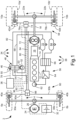
- the motor vehicle 2 shown which is a commercial vehicle, has a single-tire front axle 4 with two wheels 6a, 6b and a double-tire rear axle 8 with a total of, for example, four wheels 10a, 10a', 10b, 10b'.
- the motor vehicle 2 can be driven selectively or jointly by an internal combustion engine 12 and/or by an electric machine 24 that can be operated optionally as a motor or generator.
- the internal combustion engine 12 is in drive connection with the wheels 10a, 10a', 10b, 10b' of the rear axle 8 via a separating clutch 14, a manual transmission 16, a cardan shaft 18, a first axle differential 20 and a drive shaft 22a, 22b in each case.
- the electric machine 24 is connected to the wheels 6a, 6b of the front axle 4 via a drive shaft 26, a second axle differential 28 and a drive shaft 30a, 30b.
- the electric machine 24 In motor mode, the electric machine 24 is supplied with electrical energy from an associated electrical energy storage device 32.
- In generator mode, the electric machine 24 is preferably used to charge the energy storage device 32.
- the braking system 34 of the motor vehicle 2 is electronically controllable and comprises, in addition to an electronic control unit 36, a service braking system 38 with pressure-medium-operated, wheel brakes 40a, 40b, 42a, 42b designed as friction brakes, a continuous braking system or secondary brake 44 in the form of a hydrodynamic or electrodynamic retarder, the electric machine 24 which is in drive connection with the wheels 6a, 6b of the front axle 4, and a foot brake valve 48 which can be actuated by means of a brake pedal 46, can be connected directly or indirectly to a brake value transmitter 50 designed as a travel sensor and a brake pedal actuator 52.
- the brake pedal actuator 52 serves to generate a restoring force acting on the brake pedal 46. It is connected to the electronic control unit 36 via an electrical control line 54 for its control.
- An axially or rotationally acting drive element 53 is arranged on the brake pedal actuator 52, by means of which a signal force can be exerted on the brake pedal 46 in addition to the aforementioned restoring force.
- the service brake system 38 is designed as a compressed air brake system and has a compressed air supply device 56 and two brake circuits 58, 60.
- the compressed air supply device 56 comprises a compressor 62, a pressure regulator 64 and a multi-circuit protection valve 66. Compressed air is supplied from the compressor 62, which can be driven by the internal combustion engine 12, to the two brake circuits 58, 60 via the pressure regulator 64 and the multi-circuit protection valve 66.
- the first brake circuit 58 has a first pressure accumulator 70 and a first supply line 68, which leads from the multi-circuit protection valve 66 to the foot brake valve 48.
- a first axle brake line 72 is connected to the foot brake valve 48, into which a brake pressure is introduced depending on the actuation of the brake pedal 46.
- the first axle brake line 72 leads to a first axle valve module 74 on the rear axle 8.
- the first axle valve module 74 comprises a relay valve and preferably one ABS valve arrangement (not shown) for each wheel pair 10a, 10a'; 10b, 10b' of the rear axle 8. It is pointed out that the presence of the ABS valve arrangement of the first axle valve module 74 is only an optional embodiment, in particular if the first axle valve module 74 is designed as an electronically controllable valve module. has been.
- a wheel brake line 76a, 76b is led from the first axle valve module 74 to the associated wheel brake 42a, 42b of the rear axle 8.
- the relay valve of the first axle valve module 74 is primarily controlled electronically as a function of the braking value detected by the braking value sensor 50 of the foot brake valve 48.
- the braking value sensor 50 is connected to the electronic control unit 36 via an electrical sensor line 78 and the first axle valve module 74 is connected via an electrical control line 80.
- the relay valve of the first axle valve module 74 is controlled pneumatically as a function of the braking pressure present in the axle brake line 72.
- the second brake circuit 60 has a second supply line 82 and a second pressure accumulator 84, wherein the second supply line 82 is guided from the multi-circuit protection valve 66 via the second pressure accumulator 84 to the foot brake valve 48.
- a second axle brake line 86 into which a brake pressure is introduced depending on the actuation of the brake pedal 46, runs from the foot brake valve 48 to a second axle valve module 88.
- This second axle valve module 88 also comprises a relay valve (not shown) and one ABS valve arrangement per wheel 6a, 6b of the front axle 4. From the ABS valve arrangements of the second axle valve module 88, one wheel brake line 90a, 90b is guided to the associated wheel brake 40a, 40b of the front axle 4.
- the relay valve of the second axle valve module 88 is also primarily controlled electronically as a function of the braking value detected by the braking value sensor 50 of the foot brake valve 48 and is connected to the electronic control unit 36 via an electrical control line 92. In the case of redundancy, the relay valve of the second axle valve module 88 is also pneumatically controlled as a function of the braking pressure present in the second axle brake line 86.
- the retarder 44 is connected to an output shaft of the manual transmission 16 and is connected to the wheels 10a, 10a', 10b, 10b' of the rear axle 8 via the cardan shaft 18, the axle differential 20 and the drive shafts 22a, 22b.
- the retarder 44 is connected to the electronic control unit 36 via an electrical control line 94.
- the electric machine 24 is also connected to the drive shaft 18. via an electrical control line 96 with the electronic control unit 36.
- the braking deceleration desired by the driver which corresponds to the braking value detected by the braking value sensor 50 when the brake pedal 46 is actuated, is distributed in the electronic control unit 36 between the components of the braking system 34.
- these are the service braking system 38, the retarder 44 and the electric motor 24 in generator mode, with the distribution of the braking force being prioritized in the order of electric motor 24, retarder 44 and service braking system 38.
- the motor vehicle 2 is initially braked without wear using the electric machine 24 operated as a generator, with partial recovery of the kinetic energy of the motor vehicle 2 and charging of the electrical energy storage device 32 (recuperation).
- the motor vehicle 2 is then further braked without wear using the retarder 44 before the friction brakes 40a, 40b, 42a, 42b of the service brake system 38 are actuated.
- the distribution or the process planning or the sequencing or prioritization with regard to the use of the braking force from the aforementioned brake components (service brake system 38, the retarder 44 and the electric machine 24 in generator mode) is decided depending on the determined driver braking request (by the electronic control unit 36, for example).
- a corresponding restoring force in the form of a signal force is generated by means of the axially or rotationally acting drive element 53 on the brake pedal actuator 52 and introduced into the brake pedal 46.
- feedback is provided to drivers by an increased resistance feeling or resistance force on the brake pedal 46 or the foot brake valve 48 when the driver presses the brake pedal 46 or the foot brake valve 48 should or must be informed about the distribution of the braking force between the components 24, 38, 44 when the brake pedal 46 is deflected in a certain way. It should be taken into account that the deflection of the brake pedal 46 does not always reflect a desired vehicle deceleration. For example, in advanced braking systems such as ESP (Electronic Stability Program), ESC (Electronic Stability Control), ASR (Anti-Slip Regulation), the vehicle deceleration and/or braking force requirement can be controlled independently of the driver's braking request.
- ESP Electronic Stability Program
- ESC Electronic Stability Control
- ASR Anti-Slip Regulation
- the invention provides that, in the event of at least one change in the distribution of the braking force between the components 24, 38, 44 of the braking system 34, for example when one of the components 24, 38, 44 of the braking system 34 is switched on and/or off, a short-term signal force that can be felt haptically on the driver's foot is superimposed on the restoring force by means of the brake pedal actuator 52. How this is preferably done is shown by way of example in the diagram of Fig. 2 shown.
- the course of the resistance force F BP acting on the brake pedal 46 over time t during a braking process is shown (F BP (t)).
- the resistance force F BP results from the sum of the resistance forces generated within the foot brake valve 48 and the restoring force controlled by means of the foot brake actuator 52.
- the braking process begins at time t0 with an actuation of the brake pedal 46 by the driver, whereby the motor vehicle 2 is initially only decelerated by the electric machine 24 operated as a generator.
- the retarder 44 is switched on, which is indicated to the driver by a haptically perceptible signal force S1 in the form of a pulse-shaped increase in the restoring force with the strength H1 and the duration T1.
- the braking torque of the electric machine 24 is then continuously reduced and the braking torque of the retarder 44 is increased accordingly until the electric machine 24 is completely switched off at time t2.
- the switching off of the electric machine 24 is communicated to the driver by a haptically perceptible signal force S2 in the form of a double-pulse-shaped increase in the restoring force with the strength H2 and the duration T2.
- the strength H2 of the second signal force S2 is noticeably lower than the strength H1 of the first signal force S1 and the duration T2 of the second signal force S2 is greater than the duration T1 of the first signal force S1 (H2 ⁇ H1, T2 > T1).
- the switching off of the electric machine 24 and the switching on of the retarder 44 can be necessary, for example, because the electrical energy storage device 32 is largely charged and/or the electric machine 24 has reached its overheating limit.
- the service brake system 38 with the friction brakes 40a, 40b, 42a, 42b is activated, which is indicated to the driver by a haptically perceptible signal force S3 in the form of a vibration sequence that can be felt as a vibration and includes several oscillations of the restoring force with the amplitude A1, the frequency f1 and the duration T3.
- the braking torque of the retarder 44 is then continuously reduced and the braking torque of the friction brakes 40a, 40b, 42a, 42b is increased accordingly by increasing the applied brake pressure until the retarder 44 is completely switched off at time t4.
- the deactivation of the retarder 44 is communicated to the driver by a haptically perceptible signal force S4 in the form of a vibration sequence comprising several oscillations of the restoring force with the amplitude A2, the frequency f2 and the duration T4.
- the amplitude A2 of the fourth signal force S4 is greater than the amplitude A1 of the third signal force S3, the frequency f2 of the fourth signal force S4 is smaller than the frequency f1 of the third signal force S3 and the duration T4 of the fourth signal force S4 is smaller than the duration T3 of the third signal force S3 (A2 > A1, f2 ⁇ f1, T4 ⁇ T3).
- Switching off the retarder 44 and switching on the service brake system 38 may be necessary, for example, because the retarder 44 can no longer generate usable braking torque due to a reduced driving speed of the motor vehicle 2 and/or has reached its overheating limit.
- the different designs of the signal forces S1, S2, S3, S4 make it possible to clearly identify the respective activation and deactivation processes. If there is no emergency braking, the driver can influence the distribution of the braking force between the components 24, 38, 44 of the braking system 38 by operating the brake pedal 46, for example by partially releasing the brake pedal 46 to return to the previous distribution of the braking force.
Landscapes
- Engineering & Computer Science (AREA)
- Transportation (AREA)
- Mechanical Engineering (AREA)
- Power Engineering (AREA)
- Automation & Control Theory (AREA)
- Physics & Mathematics (AREA)
- Electromagnetism (AREA)
- Human Computer Interaction (AREA)
- Regulating Braking Force (AREA)
Description
- Die Erfindung betrifft eine Bremsanlage eines Kraftfahrzeugs sowie ein Verfahren zur Steuerung dieser Bremsanlage, welches eine Betriebsbremsanlage mit druckmittelbetätigbaren Reibungsbremsen, eine Dauerbremsanlage, ausgebildet als hydrodynamischer oder elektrodynamischer Retarder, mindestens eine mit den Rädern an einer Fahrzeugachse in Triebverbindung stehende, zumindest als Generator betreibbare Elektromaschine, sowie ein mittels eines Bremspedals betätigbares Fußbremsventil aufweist, wobei das Fußbremsventil einen Bremswertgeber und einen Bremspedalaktuator zur Erzeugung einer auf das Bremspedal wirkenden Rückstellkraft aufweist, und bei dem die genannten Komponenten der Bremsanlage mittels eines elektronischen Steuergeräts steuerbar sind, wobei der mittels einer Auslenkung des Bremspedals signalisierte Bremskraftbedarf priorisiert in der Reihenfolge von der Elektromaschine im Generatorbetrieb, von dem Retarder und von der Betriebsbremsanlage befriedigt wird, und wobei die Aufteilung der Bremskraft auf die Komponenten der Bremsanlage einem Fahrer des Kraftfahrzeugs in geeigneter Weise mitgeteilt wird.
- Schwere Nutzfahrzeuge verfügen zusätzlich zu einer Betriebsbremsanlage mit druckmittelbetätigten Reibungsbremsen meistens auch über eine verschleißfreie Dauerbremse in Form eines hydrodynamischen oder elektrodynamischen Retarders, mit welcher das Kraftfahrzeug ohne einen Einsatz der Reibungsbremsen verzögert werden kann. Beim Einsatz eines Retarders wird die Bewegungsenergie des betreffenden Fahrzeugs in Wärme umgesetzt, welche durch eine geeignete Kühlvorrichtung in die Umgebungsluft abgeführt wird. Die Bremskraft eines Retarders ist abhängig von der Fahrgeschwindigkeit des Fahrzeugs beziehungsweise von der Drehzahl der Triebwelle, zum Beispiel einer Getriebeausgangswelle eines Schaltgetriebes, mit der ein Rotor des Retarders in Triebverbindung steht. Die nutzbare Bremskraft eines Retarders ist durch die abführbare Wärmemenge begrenzt, sodass die Zuschaltung der Reibungsbremsen erforderlich sein kann, um eine Überhitzung des Retarders zu vermeiden. Zudem kann ein Kraftfahrzeug mit einem Retarder nicht bis zum Stillstand abgebremst werden, sodass die Reibungsbremsen spätestens nach Erreichen oder Unterschreiten einer Mindestfahrgeschwindigkeit zugeschaltet werden müssen.
- Mit der zunehmenden Elektrifizierung von Fahrzeugen werden auch Nutzfahrzeuge als reine Elektrofahrzeuge oder Hybridfahrzeuge jeweils mit mindestens einer Elektromaschine ausgestattet, welche mit den Rädern an einer Fahrzeugachse in Triebverbindung steht, als Motor und als Generator betreibbar ist, und somit im Generatorbetrieb ebenfalls als verschleißfreie Dauerbremse nutzbar ist. Im Generatorbetrieb einer Elektromaschine wird die Bewegungsenergie des Fahrzeugs in elektrische Energie umgewandelt, welche in einem sogenannten Rekuperationsbetrieb zum Aufladen eines elektrischen Energiespeichers genutzt werden kann. Bei einer Elektromaschine ist die nutzbare Bremskraft zum einen durch die abführbare Wärmemenge und zum anderen durch die Kapazität des Energiespeichers begrenzt, weshalb die Zuschaltung des Retarders und/oder der Reibungsbremsen erforderlich sein kann, um eine Überhitzung der Elektromaschine oder eine Überladung des Energiespeichers zu vermeiden.
- Bei einer elektronisch steuerbaren Bremsanlage mit einer integrierten Dauerbremse der gerade beschriebene Art wird die von einem Fahrer über eine Auslenkung des Bremspedals angeforderte und mittels einen am Fußbremsventil angeordneten Bremswertgeber erfasste Abbremsbedarf in Abhängigkeit von einer festgelegten Prioritätsreihenfolge und aktuellen Betriebsparametern, wie der Fahrgeschwindigkeit, der Betriebstemperatur des Retarders oder der Elektromaschine sowie dem Ladezustand des elektrischen Energiespeichers auf die Bremsanlage aufgeteilt (Brake Blending). Dabei ist die Prioritätsreihenfolge meistens derart festgelegt, dass bei einem Bremsvorgang zuerst die Elektromaschine im Generatorbetrieb zur Verzögerung des Fahrzeugs genutzt wird, um den elektrischen Energiespeicher aufzuladen, dass dann bedarfsweise der Retarder zugeschaltet wird, und dass zuletzt bedarfsweise die Betriebsbremsanlage mit den Reibungsbremsen zur Verzögerung des Fahrzeugs genutzt wird. Da der Fahrer des Kraftfahrzeugs unabhängig von der Aufteilung der Bremskraft auf die genannten Komponenten der Bremsanlage jeweils denselben Verlauf der Widerstandskraft am Bremspedal erwartet, ist üblicherweise ein Bremspedalaktuator vorhanden, welcher mit dem Bremspedal in Wirkverbindung steht, und mittels dem jeweils eine Rückstellkraft erzeugt und in das Bremspedal eingeleitet wird. Diese Rückstellkraft ist derart bemessen, dass sich zusammen mit innerhalb des Fußbremsventils erzeugten Widerstandskräften, wie der Federkraft einer auf das Bremspedal wirkenden Rückstellfeder und/oder der auf einen Steuerkolben wirksamen Druckkraft des Druckmittels, eine der gesamten Bremskraft entsprechende Widerstandskraft am Bremspedal einstellt.
- Aus der
DE 11 2007 000 071 B4 ist eine Bremsanlage eines Hybridfahrzeugs bekannt, die eine Betriebsbremsanlage mit hydraulisch betätigbaren Reibungsbremsen und mit den Rädern einer Fahrzeugachse in Triebverbindung stehende, als Motoren und als Generatoren betreibbare Elektromaschinen sowie ein über ein Bremspedal betätigbares Fußbremsventil und einen an einer Hauptbremsleitung angeschlossenen, als Drucksensor ausgebildeten Bremswertgeber umfasst. Der Antriebsstrang des Hybridfahrzeugs weist einen Verbrennungsmotor auf, der mit einem elektrischen Generator gekoppelt ist. Von den Elektromaschinen wird das Hybridfahrzeug im Motorbetrieb angetrieben und im Generatorbetrieb abgebremst. Die im Generatorbetrieb von den Elektromaschinen erzeugte elektrische Energie wird in einem Wärmestrahler in Wärme umgesetzt und an die Umgebungsluft abgegeben. Bei Bremsvorgängen wird das Hybridfahrzeug in Abhängigkeit von der Auslenkung des Bremspedals zusätzlich zu den Reibungsbremsen der Betriebsbremsanlage auch durch die als Generatoren betriebenen Elektromaschinen verzögert. Bei Bremsvorgängen mit geringer Auslenkung des Bremspedals ist dagegen vorgesehen, dass das Hybridfahrzeug nur mit den Reibungsbremsen der Betriebsbremsanlage abgebremst wird, um eine genaue Dosierbarkeit der Bremskraft zu gewährleisten. - In der
US 2004/0251095 A1 ist eine Bremsanlage eines Elektrofahrzeugs beschrieben, welche eine Betriebsbremsanlage mit hydraulisch betätigbaren Reibungsbremsen und eine mit den Rädern einer Fahrzeugachse in Triebverbindung stehende, als Motor und als Generator betreibbare Elektromaschine sowie ein über ein Bremspedal betätigbares Hauptbremsventil, einen an einem Bremshebel des Bremspedals angeordneten Bremswertgeber und einen Bremspedalaktuator zur Erzeugung einer auf das Bremspedal wirksamen Rückstellkraft umfasst. Der Bremspedalaktuator ist in einer ersten Ausführung als ein Elektromotor ausgebildet, der über ein Zahnstangengetriebe mit dem Bremshebel in Stellverbindung steht. In einer zweiten Ausführung ist der Bremspedalaktuator als ein hydraulischer oder pneumatischer Stellzylinder ausgebildet, dessen Kolbenstange mit dem Bremshebel in Stellverbindung ist. Bei Bremsvorgängen wird die über die Auslenkung des Bremspedals angeforderte Bremskraft zwischen den Reibungsbremsen der Betriebsbremsanlage und der als Generator betriebenen Elektromaschine aufgeteilt. Dabei wird mittels des Bremspedalaktuators eine Rückstellkraft erzeugt und in den Bremshebel eingeleitet, welche dem generatorisch erzeugten Anteil der Bremskraft entspricht, sodass der Fahrer am Bremspedal dieselbe Rückstellkraft wie bei einem rein hydraulisch bewirkten Bremsvorgang wahrnimmt. - In der
DE 10 2012 209 157 A1 ist eine Bremsanlage eines Elektro- oder Hybridfahrzeugs offenbart, welche eine Betriebsbremsanlage mit druckmittelbetätigten Reibungsbremsen und mindestens eine mit den Rädern einer Fahrzeugachse in Triebverbindung stehende, als Motor und als Generator betreibbare Elektromaschine sowie ein mittels eines Bremspedals betätigbares Fußbremsventil mit einem Bremswertgeber und einem Bremspedalaktuator zur Erzeugung einer auf das Bremspedal wirksamen Rückstellkraft umfasst. Bei Bremsvorgängen wird das Kraftfahrzeug zunächst durch die als Generator betriebene Elektromaschine verzögert. Bevor die Elektromaschine ihr maximales Bremsmoment erreicht, wird die Betriebsbremsanlage mit den Reibungsbremsen aktiviert. In einer Regelungseinrichtung wird in Abhängig von der Auslenkung des Bremspedals und des maximal oder aktuell verfügbaren oder rekuperierbaren Bremsmomentes der Elektromaschine eine Rückstellkraft bestimmt, welche mittels des Bremspedalaktuators eingestellt wird. Bevor die Elektromaschine ihr maximales Bremsmoment erreicht, wird die Betriebsbremsanlage mit den Reibungsbremsen zugeschaltet, welches dem Fahrer des Fahrzeugs über eine erhöhte Rückstellkraft am Bremspedal zur Kenntnis gebracht wird. - Aus der
DE 10 2018 114 848 A1 ist ein Fußbremsventil einer elektronisch steuerbaren Druckluftbremsanlage bekannt, welches einen als Wegsensor ausgebildeten Bremswertgeber und einen elektropneumatischen Bremspedalaktuator zur Erzeugung einer auf das Bremspedal wirksamen Rückstellkraft aufweist. Der Bremspedalaktuator ist mit einem offenen Druckraum, welcher über ein Einlassventil belüftbar und über ein Auslassventil entlüftbar ist, benachbart zu einem Federteller an das Gehäuse des Fußbremsventils angeflanscht. Der Federteller ist axial verschiebbar in dem Gehäuse des Fußbremsventils geführt und dient primär zur Abstützung einer Rückstellfeder, an der gegenüberliegend ein über das Bremspedal axial verschiebbarer Stößelkolben anliegt. Über den Bremspedalaktuator kann eine abschnittsweise oder stufenweise erhöhte Rückstellkraft in das Bremspedal eingeleitet werden. Bei einem Bremsvorgang mit aktivierter ABS-Regelung können über den Bremspedalaktuator Druckimpulse in das Bremspedal eingeleitet werden, welche von dem Fahrer als Vibration wahrnehmbar sind und die aktuell wirksame ABS-Regelung anzeigen sollen. - In einem Kraftfahrzeug mit einer Bremsanlage, welche eine Betriebsbremsanlage mit Reibungsbremsen, einen Retarder und mindestens eine als Generator betreibbare Elektromaschine umfasst, kann dem Fahrer während eines Bremsvorgangs die Aufteilung der Bremskraft auf die Komponenten der Bremsanlage beispielsweise in einem Display im Armaturenbrett angezeigt werden. Der Fahrer kann den Bremsvorgang dann über die Betätigung des Bremspedals derart beeinflussen, dass zum Beispiel die Betätigung der Reibungsbremsen der Betriebsbremsanlage und damit ein Verschleiß der Reibbeläge sowie der Bremsscheiben oder Bremstrommeln vermieden wird. Da der Fahrer während eines starken Bremsvorgangs den Blick aber nicht von dem vor ihm liegenden Verkehrsraum nehmen sollte, um das Kraftfahrzeug auf der Fahrbahn zu halten, einen Aufprall auf ein anderes Kraftfahrzeug zu verhindern oder ein Hindernis zu umfahren, ist zusätzlich eine haptisch am Bremspedal fühlbare Information über die aktuelle Aufteilung der Bremskraft wünschenswert.
- Der vorliegenden Erfindung liegt daher die Aufgabe zugrunde, ein Verfahren zur Steuerung einer Bremsanlage eines Kraftfahrzeugs der eingangs genannten Art vorzustellen, mit welchem dem Fahrer die Aufteilung seines Bremswunsches auf die Komponenten der Bremsanlage in geeigneter Weise mitgeteilt werden kann. Außerdem soll eine Bremsanlage dargestellt und beschrieben werden, mit dem das genannte Verfahren betrieben werden kann.
- Die Lösung der verfahrensbezogenen Aufgabe ist durch ein Verfahren mit den Merkmalen des Anspruchs 5 gelöst. Die Merkmale des unabhängigen Vorrichtungsanspruchs (Anspruch 1) kennzeichnen eine Bremsanlage, welches die vorrichtungsbezogene Aufgabe löst. Vorteilhafte Ausgestaltungen und Weiterbildungen sind in den jeweils zugeordneten abhängigen Ansprüchen definiert.
- Es wird eine Bremsanlage eines Kraftfahrzeugs beansprucht, welche eine Betriebsbremsanlage mit druckmittelbetätigbaren Reibungsbremsen, eine Dauerbremsanlage, ausgebildet als hydrodynamischer oder elektrodynamischer Retarder, mindestens eine mit den Rädern an einer Fahrzeugachse in Triebverbindung stehende, zumindest als Generator betreibbare Elektromaschine, sowie ein mittels eines Bremspedals betätigbares Fußbremsventil aufweist, wobei das Fußbremsventil einen Bremswertgeber und einen Bremspedalaktuator zur Erzeugung einer auf das Bremspedal wirkenden Rückstellkraft aufweist, und bei dem die genannten Komponenten der Bremsanlage mittels eines elektronischen Steuergeräts steuerbar sind, wobei der signalisierte Bremskraftbedarf priorisiert in der Reihenfolge von der Elektromaschine im Generatorbetrieb, von dem Retarder und von der Betriebsbremsanlage befriedigt wird, und wobei die Aufteilung der Bremskraft auf die Komponenten der Bremsanlage einem Fahrer des Kraftfahrzeugs in geeigneter Weise mitteilbar ist.
- Zur Lösung der vorrichtungsbezogenen Aufgabe ist bei dieser Bremsanlage vorgesehen, dass der Bremspedalaktuator elektrisch wirksam ausgebildet ist und ein drehbares oder axial verschiebbares Triebelement aufweist, und dass das Triebelement des Bremspedalaktuators unmittelbar oder mittelbar mit einem Bremshebel des Bremspedals oder mit einem Stößelkolben des Fußbremsventils in Stellverbindung ist.
- In einer bevorzugten Ausführungsform wird der Bremskraft mittels einer Auslenkung des Bremspedals signalisiert. In einer anderen bevorzugten Ausführungsform wird der Bremskraftbedarf wird automatisch durch den elektronisch geregelten Bremsanforderungen signalisiert. Beispielsweise in den fortschrittlichen Bremsanlagen wie ESP (Electronic Stability Program), ESC (Electronic Stability Control), ASR (Anti-Slip Regulation) kann die Fahrzeug-verzögerung und/oder Bremskraftbedarf unabhängig vom Fahrerbremswünsch, der mittels einer Auslenkung des Bremspedals gegeben ist, kontrolliert oder kalibriert werden.
- Diese elektrisch wirksame Ausbildung des Bremspedalaktuators hat gegenüber den aus dem Stand der Technik bekannten Ausführungen als hydraulischer oder pneumatischer Stellzylinder die Vorteile eines besseren beziehungsweise schnelleren Ansprechverhaltens und einer genaueren Dosierbarkeit der Rückstellkraft und der auf das Bremspedal einwirkenden Signalkraft.
- Gemäß einer ersten Weiterbildung dieser Bremsanlage ist vorgesehen, dass der Bremspedalaktuator als ein Elektromotor mit einer drehbaren Rotorwelle ausgebildet ist. Die Rotorwelle des Elektromotors ist hierbei über ein Spindelgetriebe unmittelbar oder mittelbar mit dem Bremshebel des Bremspedals oder mit dem Stößelkolben des Fußbremsventils verbunden.
- Alternativ dazu kann vorgesehen sein, dass der Bremspedalaktuator als ein Elektromagnet mit einem axial verschiebbaren Anker ausgebildet ist, wobei der Anker des Elektromagneten unmittelbar oder mittelbar mit dem Bremshebel des Bremspedals oder mit dem Stößelkolben des Fußbremsventils in Stellverbindung ist.
- Demnach betrifft die Erfindung zunächst ein Verfahren zur Steuerung einer Bremsanlage eines Kraftfahrzeugs, welches eine Betriebsbremsanlage mit druckmittelbetätigbaren Reibungsbremsen, eine Dauerbremsanlage, ausgebildet als hydrodynamischer oder elektrodynamischer Retarder, mindestens eine mit den Rädern an einer Fahrzeugachse in Triebverbindung stehende, zumindest als Generator betreibbare Elektromaschine, sowie ein mittels eines Bremspedals betätigbares Fußbremsventil aufweist, wobei das Fußbremsventil einen Bremswertgeber und einen Bremspedalaktuator zur Erzeugung einer auf das Bremspedal wirkenden Rückstellkraft aufweist, und bei dem die genannten Komponenten der Bremsanlage mittels eines elektronischen Steuergeräts steuerbar sind, wobei der mittels einer Auslenkung des Bremspedals signalisierte Bremskraftbedarf priorisiert in der Reihenfolge von der Elektromaschine im Generatorbetrieb, von dem Retarder und von der Betriebsbremsanlage befriedigt wird, und wobei die Aufteilung der Bremskraft auf die Komponenten der Bremsanlage einem Fahrer des Kraftfahrzeugs in geeigneter Weise mitgeteilt wird.
- Zur Lösung der verfahrensbezogenen Aufgabe ist bei dieser Bremsanlage vorgesehen, dass bei mindestens einer Änderung der Aufteilung der Bremskraft auf die Komponenten der Bremsanlage mittels des Bremspedalaktuators die auf das Bremspedal wirkende Rückstellkraft kurzzeitig mit einer haptisch wahrnehmbaren Signalkraft überlagert wird.
- Von Vorteil ist hierbei, dass der Fahrer des Kraftfahrzeugs nur über einen sehr kurzen Zeitraum über eine Änderung der Aufteilung der Bremskraft auf die Komponenten der Bremsanlage informiert wird, also keine dauerhafte Änderung der auf das Bremspedal wirkenden Rückstellkraft spürbar ist. Da diese Informationsvermittlung zudem über das Bremspedal auf den Fuß des Fahrers wirkt, kann dieser seine Augen weiter konzentriert auf den vor ihm liegenden Verkehrsraum richten.
- Gemäß einer ersten Weiterbildung des beschriebenen Verfahrens ist vorgesehen, dass bei einer Zuschaltung oder einer Abschaltung wenigstens einer der Komponenten der Bremsanlage mittels des Bremspedalaktuators die auf das Bremspedal wirkende Rückstellkraft kurzzeitig mit einer haptisch wahrnehmbaren Signalkraft überlagert wird. Auch bei dieser Verfahrensvariante gelten die gerade genannten Vorteile. Allerdings wird der Fahrer bei dieser Weiterbildung des Verfahrens nur dann mittels der zusätzlich auf das Bremspedal wirkenden Signalkraft informiert, wenn eine der Komponenten der Bremsanlage vollständig zugeschaltet oder vollständig abgeschaltet wird.
- Durch das Erzeugen einer haptisch wahrnehmbaren Signalkraft mittels des Bremspedalaktuators und deren Einleiten in das Bremspedal wird der Fahrer des Kraftfahrzeugs über eine gerade stattfindende beziehungsweise gerade erfolgte Änderung der Aufteilung der Bremskraft auf die Komponenten der Bremsanlage informiert. Also beispielsweise über die Zuschaltung oder Abschaltung der Elektromaschine in deren generatorischen Betrieb, des Retarders oder der Betriebsbremsanlage. Da dem Fahrer diese Information über das Bremspedal in seinen Fuß signalisiert wird, braucht dieser zur Kenntnisnahme der Information seinen Blick nicht von dem vor ihm liegenden Verkehrsraum abwenden. In Reaktion auf die Signalkraft kann der Fahrer über eine entsprechende Betätigung des Bremspedals die Aufteilung der Bremskraft auf die erwähnten Komponenten der Bremsanlage beeinflussen. So kann er beispielsweise während des elektrischen Bremsens im Generatorbetrieb der Elektromaschine durch ein leichtes Lösen des Bremspedals energetisch sinnvoll die Zuschaltung des Retarders verhindern, sofern die Verkehrssituation eine geringere Bremsverzögerung zulässt.
- Hierbei kann es für die Wahrnehmbarkeit der aktuellen Aufteilung der Bremskraft auf die Komponenten der Bremsanlage vor Vorteil sein, wenn die die Rückstellkraft am Bremspedal verändernde Signalkraft als mindestens eine impulsförmige Erhöhung der Rückstellkraft wirksam ist.
- Um während eines Bremsvorgangs eine Unterscheidung zwischen dem Zuschalten und dem Abschalten der Komponenten der Bremsanlage zu ermöglichen, ist bevorzugt vorgesehen, dass sich bei unterschiedlichen Änderungen der Aufteilung der Bremskraft eingesteuerten impulsförmigen Signalkräfte hinsichtlich ihrer Anzahl und/oder Stärke und/oder Dauer voneinander unterscheiden. Hierauf wird noch bei der Erläuterung eines Ausführungsbeispiels eingegangen.
- Gemäß einer weiteren Verfahrensvariante ist vorgesehen, dass die Signalkraft in Form einer am Bremspedal als Vibration spürbaren, mehrere Schwingungen der Rückstellkraft umfassenden Schwingungssequenz eingesteuert wird. Bei dieser Ausführung der Signalkraft können sich die bei unterschiedlichen Änderungen der Aufteilung der Bremskraft eingesteuerten Schwingungssequenzen hinsichtlich ihrer Frequenz und/oder Amplitude und/oder Dauer voneinander unterscheiden.
- Selbstverständlich können die genannten Verfahrensvarianten auch in Kombination zur Anwendung kommen, beispielsweise derart, dass die Zuschaltung oder Abschaltung mindestens einer Komponente der Bremsanlage, beispielsweise der generatorisch betreibbaren Elektromaschine, über eine Signalkraft in Form mindestens einer impulsförmigen Erhöhung der Rückstellkraft signalisiert wird. Im Unterschied dazu wird die Zuschaltung oder Abschaltung einer anderen Komponente der Bremsanlage, beispielsweise der Betriebsbremsanlage mit den Reibungsbremsen, über eine Signalkraft in Form einer als Vibration spürbaren, mehrere Schwingungen der Rückstellkraft umfassende Schwingungssequenz dem Fahrer zur Kenntnis gebracht.
- Das Verfahren und die Bremsanlage mit den Merkmalen der Erfindung werden nachstehend anhand eines in der beigefügten Zeichnung dargestellten Ausführungsbeispiels anschaulich erläutert. In der Zeichnung zeigt
-
Fig. 1 in einer schematischen Ansicht ein Kraftfahrzeug mit einer Bremsanlage, welches die Merkmale der Erfindung aufweist, und -
Fig. 2 ein Kraft-Zeit-Diagramm, in welchem der Verlauf eines Bremsvorgangs mit einer Anwendung des erfindungsgemäßen Steuerungsverfahrens veranschaulicht ist. - Das in
Fig. 1 abgebildete Kraftfahrzeug 2, bei dem es sich um ein Nutzfahrzeug handelt, weist eine einfachbereifte Vorderachse 4 mit zwei Rädern 6a, 6b und eine doppeltbereifte Hinterachse 8 mit insgesamt bspw. vier Rädern 10a, 10a', 10b, 10b' auf. Das Kraftfahrzeug 2 kann wahlweise oder gemeinsam von einem Verbrennungsmotor 12 und/oder von einer wahlweise als Motor oder Generator betreibbaren Elektromaschine 24 angetrieben werden. Der Verbrennungsmotor 12 steht über eine Trennkupplung 14, ein Schaltgetriebe 16, eine Kardanwelle 18, ein erstes Achsdifferential 20 und jeweils eine Antriebswelle 22a, 22b mit den Rädern 10a, 10a', 10b, 10b' der Hinterachse 8 in Antriebsverbindung. Die Elektromaschine 24 steht über eine Triebwelle 26, ein zweites Achsdifferential 28 und jeweils eine Antriebswelle 30a, 30b mit den Rädern 6a, 6b der Vorderachse 4 in Antriebsverbindung. Im Motorbetrieb wird die Elektromaschine 24 aus einem zugeordneten elektrischen Energiespeicher 32 mit elektrischer Energie versorgt. Im generatorischen Betrieb wird die Elektromaschine 24 bevorzugt zum Laden des Energiespeichers 32 genutzt. - Die Bremsanlage 34 des Kraftfahrzeugs 2 ist elektronisch steuerbar und umfasst neben einem elektronischen Steuergerät 36 eine Betriebsbremsanlage 38 mit druckmittelbetätigbaren, als Reibungsbremsen ausgeführten Radbremsen 40a, 40b, 42a, 42b, eine Dauerbremsanlage oder Sekundärbremse 44 in Form eines hydrodynamischen oder elektrodynamischen Retarders, die mit den Rädern 6a, 6b der Vorderachse 4 in Antriebsverbindung stehende Elektromaschine 24, sowie ein mittels eines Bremspedals 46 betätigbares Fußbremsventil 48 mit einem als Stellwegsensor ausgeführten Bremswertgeber 50 und einem Bremspedalaktuator 52 direkt oder indirekt verbindbar ist. Der Bremspedalaktuator 52 dient zur Erzeugung einer auf das Bremspedal 46 wirkenden Rückstellkraft. Er ist zu seiner Ansteuerung über eine elektrische Steuerleitung 54 mit dem elektronischen Steuergerät 36 verbunden.
- An dem Bremspedalaktuator 52 ist ein axial oder rotatorisch wirkendes Triebelement 53 angeordnet, mittels dem zusätzlich zu der erwähnten Rückstellkraft eine Signalkraft auf das Bremspedal 46 ausgeübt werden kann.
- Die Betriebsbremsanlage 38 ist als eine Druckluftbremsanlage ausgeführt und weist eine Druckluftversorgungseinrichtung 56 und zwei Bremskreise 58, 60 auf. Die Druckluftversorgungseinrichtung 56 umfasst einen Kompressor 62, einen Druckregler 64 und ein Mehrkreisschutzventil 66. Von dem Kompressor 62, der von dem Verbrennungsmotor 12 antreibbar ist. Mittels des Kompressors 62 wird Druckluft über den Druckregler 64 und das Mehrkreisschutzventil 66 in die beiden Bremskreise 58, 60 gefördert.
- Der erste Bremskreis 58 weist einen ersten Druckspeicher 70 und eine erste Vorratsleitung 68 auf, welche von dem Mehrkreisschutzventil 66 zu dem Fußbremsventil 48 führt. An dem Fußbremsventil 48 ist eine erste Achsbremsleitung 72 angebunden, in welche abhängig von der Betätigung des Bremspedals 46 ein Bremsdruck eingesteuert wird. Die erste Achsbremsleitung 72 führt einem ersten Achsventilmodul 74 an der Hinterachse 8.
- Das erste Achsventilmodul 74 umfasst ein Relaisventil und jeweils vorzugsweise eine nicht dargestellte ABS-Ventilanordnung pro Radpaar 10a, 10a'; 10b, 10b' der Hinterachse 8. Es wird darauf hingewiesen, dass die Anwesenheit der ABS-Ventilanordnung des ersten Achsventilmoduls 74 nur eine optionale Ausführung ist, insbesondere wenn das erste Achsventilmodul 74 als elektronisch ansteuerbare Ventilmodul ausgebildet worden ist. Von dem ersten Achsventilmodul 74 ist jeweils eine Radbremsleitung 76a, 76b an die zugeordnete Radbremse 42a, 42b der Hinterachse 8 geführt. Das Relaisventil des ersten Achsventilmoduls 74 wird primär in Abhängigkeit von dem mittels des Bremswertgebers 50 des Fußbremsventils 48 erfassten Bremswert elektronisch gesteuert. Hierzu ist der Bremswertgeber 50 über eine elektrische Sensorleitung 78 und das erste Achsventilmodul 74 über eine elektrische Steuerleitung 80 mit dem elektronischen Steuergerät 36 verbunden. Im Redundanzfall, also bei ausgefallener elektronischer Steuerung, wird das Relaisventil des ersten Achsventilmoduls 74 in Abhängigkeit des in der Achsbremsleitung 72 anliegenden Bremsdruckes pneumatisch gesteuert.
- Der zweite Bremskreis 60 weist eine zweite Vorratsleitung 82 und einen zweiten Druckspeicher 84 auf, wobei die zweite Vorratsleitung 82 von dem Mehrkreisschutzventil 66 über den zweiten Druckspeicher 84 zu dem Fußbremsventil 48 geführt ist. Von dem Fußbremsventil 48 verläuft eine zweite Achsbremsleitung 86, in die abhängig von der Betätigung des Bremspedals 46 ein Bremsdruck eingesteuert wird, zu einem zweiten Achsventilmodul 88. Dieses zweite Achsventilmodul 88 umfasst ebenfalls ein nicht dargestelltes Relaisventil und jeweils eine ABS-Ventilanordnung pro Rad 6a, 6b der Vorderachse 4. Von den ABS-Ventilanordnungen des zweiten Achsventilmoduls 88 ist jeweils eine Radbremsleitung 90a, 90b an die zugeordnete Radbremse 40a, 40b der Vorderachse 4 geführt. Das Relaisventil des zweiten Achsventilmoduls 88 wird ebenfalls primär in Abhängigkeit von dem mittels des Bremswertgebers 50 des Fußbremsventils 48 erfassten Bremswert elektronisch gesteuert und ist hierzu über eine elektrische Steuerleitung 92 mit dem elektronischen Steuergerät 36 verbunden. Im Redundanzfall wird das Relaisventil des zweiten Achsventilmoduls 88 ebenfalls in Abhängigkeit des in der zweiten Achsbremsleitung 86 anliegenden Bremsdruckes pneumatisch gesteuert.
- Der Retarder 44 ist mit einer Ausgangswelle des Schaltgetriebes 16 antriebsverbunden und steht über die Kardanwelle 18, das Achsdifferential 20 und die Antriebswellen 22a, 22b mit den Rädern 10a, 10a', 10b. 10b' der Hinterachse 8 in Antriebsverbindung. Zur elektronischen Steuerung ist der Retarder 44 über eine elektrische Steuerleitung 94 mit dem elektronischen Steuergerät 36 verbunden. Ebenso steht die Elektromaschine 24 über eine elektrische Steuerleitung 96 mit dem elektronischen Steuergerät 36 in Verbindung.
- Bei einem Bremsvorgang wird die von dem Fahrer gewünschte Bremsverzögerung, welche bei einer Betätigung des Bremspedals 46 dem von dem Bremswertgeber 50 erfassten Bremswert entspricht, in dem elektronischen Steuergerät 36 auf die Komponenten der Bremsanlage 34 aufgeteilt. Diese sind wie erwähnt die Betriebsbremsanlage 38, der Retarder 44 und die Elektromaschine 24 im Generatorbetrieb, wobei die Aufteilung der Bremskraft priorisiert in der Reihenfolge Elektromaschine 24, Retarder 44 und Betriebsbremsanlage 38 erfolgt.
- Hierdurch wird das Kraftfahrzeug 2 zunächst mit der als Generator betriebenen Elektromaschine 24 unter teilweiser Rückgewinnung der kinetischen Energie des Kraftfahrzeugs 2 und Aufladung des elektrischen Energiespeichers 32 (Rekuperation) verschleißfrei abgebremst. Danach wird das Kraftfahrzeug 2 mit dem Retarder 44 verschleißfrei weiter abgebremst, bevor die Reibungsbremsen 40a, 40b, 42a, 42b der Betriebsbremsanlage 38 betätigt werden. In einer bevorzugten Ausführungsform ist auch vorstellbar, wobei die Aufteilung bzw. die Ablaufplanung oder die Sequenzierung oder Priorisierung in Bezug auf den Einsatz der Bremskraft von den erwähnten Bremskomponenten (Betriebsbremsanlage 38, der Retarder 44 und die Elektromaschine 24 im Generatorbetrieb) abhängig von dem festgestellten Fahrerbremswünsch (durch bspw. den elektronischen Steuergerät 36) entscheidet ist. Da der Fahrer am Bremspedal 46 bei einer bestimmten Auslenkung des Bremspedals 46 unabhängig von der Aufteilung der Bremskraft auf die Komponenten 24, 38, 44 der Bremsanlage 34 die weitgehend selbe Widerstandskraft FBP wahrnehmen soll, wird in einer bevorzugten Ausführungsform mittels des axial oder rotatorisch wirkenden Triebelements 53 am Bremspedalaktuator 52 eine entsprechende Rückstellkraft in Form einer Signalkraft erzeugt und in das Bremspedal 46 eingeleitet.
- In einer anderen bevorzugten Ausführungsform wird ein Feedback an Fahrer durch einen erhöhten Widerstandsgefühl oder einen Widerstandkraft am Bremspedal 46 oder am Fußbremsventil 48 gegeben, wenn der Fahrer am Bremspedal 46 oder am Fußbremsventil 48 bei einer bestimmten Auslenkung des Bremspedals 46 über die Aufteilung der Bremskraft auf die Komponenten 24, 38, 44 informiert werden soll oder muss. Hierbei sollte man berücksichtigen, dass die Auslenkung des Bremspedals 46 nicht immer eine gewünschte Fahrzeugverzögerung reflektiert wird. Bspw. in den fortschrittlichen Bremsanlagen wie ESP (Electronic Stability Program), ESC (Electronic Stability Control), ASR (Anti-Slip Regulation) kann die Fahrzeugverzögerung und/oder Bremskraftbedarf unabhängig vom Fahrerbremswünsch kontrolliert werden.
- Um den Fahrer gegebenenfalls zusätzlich zu einer optischen Anzeige in einem Display im Armaturenbrett des Kraftfahrzeugs 2 über die Aufteilung der Bremskraft auf die Komponenten 24, 38, 44 der Bremsanlage 34 zu informieren, ist erfindungsgemäß vorgesehen, dass bei mindestens einer Änderung der Aufteilung der Bremskraft auf die Komponenten 24, 38, 44 der Bremsanlage 34, beispielsweise bei der Zuschaltung und/oder Abschaltung einer der Komponenten 24, 38, 44 der Bremsanlage 34, der Rückstellkraft mittels des Bremspedalaktuator 52 eine kurzzeitige, haptisch am Fuß des Fahrers wahrnehmbare Signalkraft überlagert wird. Wie dies bevorzugt erfolgt, ist beispielhaft in dem Diagramm von
Fig. 2 dargestellt. - In dem Diagramm der
Fig. 2 ist der Verlauf der auf das Bremspedal 46 wirkenden Widerstandskraft FBP über die Zeit t während eines Bremsvorgangs dargestellt (FBP(t)). Die Widerstandkraft FBP ergibt sich aus der Summe der innerhalb des Fußbremsventils 48 erzeugten Widerstandskräfte und der mittels des Fußbremsaktuators 52 eingesteuerten Rückstellkraft. Der Bremsvorgang beginnt zum Zeitpunkt t0 mit einer Betätigung des Bremspedals 46 durch den Fahrer, wobei das Kraftfahrzeug 2 zunächst nur durch die als Generator betriebene Elektromaschine 24 verzögert wird. Zum Zeitpunkt t1 wird der Retarder 44 zugeschaltet, welches dem Fahrer durch ein haptisch wahrnehmbares Signalkraft S1 in Form einer impulsförmigen Erhöhung der Rückstellkraft mit der Stärke H1 und der Dauer T1 angezeigt wird. - Danach wird das Bremsmoment der Elektromaschine 24 kontinuierlich reduziert und das Bremsmoment des Retarders 44 entsprechend erhöht, bis die Elektromaschine 24 zum Zeitpunkt t2 vollständig abgeschaltet wird. Das Abschalten der Elektromaschine 24 wird dem Fahrer durch eine haptisch wahrnehmbare Signalkraft S2 in Form einer doppelimpulsförmigen Erhöhung der Rückstellkraft mit der Stärke H2 und der Dauer T2 mitgeteilt. Vorliegend ist beispielhaft die Stärke H2 der zweiten Signalkraft S2 erkennbar geringer als die Stärke H1 der ersten Signalkraft S1 und die Dauer T2 der zweiten Signalkraft S2 größer als die Dauer T1 der ersten Signalkraft S1 (H2 < H1, T2 > T1). Das Abschalten der Elektromaschine 24 und das Zuschalten des Retarders 44 kann beispielsweise dadurch erforderlich sein, dass der elektrische Energiespeicher 32 weitgehend geladen ist und/oder die Elektromaschine 24 ihre Überhitzungsgrenze erreicht hat.
- Zum Zeitpunkt t3 wird die Betriebsbremsanlage 38 mit den Reibungsbremsen 40a, 40b, 42a, 42b zugeschaltet, welches dem Fahrer durch eine haptisch wahrnehmbare Signalkraft S3 in Form einer als Vibration spürbaren, mehrere Schwingungen der Rückstellkraft umfassenden Schwingungssequenz mit der Amplitude A1, der Frequenz f1 und der Dauer T3 angezeigt wird. Danach wird das Bremsmoment des Retarders 44 kontinuierlich reduziert und das Bremsmoment der Reibungsbremsen 40a, 40b, 42a, 42b durch eine Erhöhung des eingesteuerten Bremsdruckes entsprechend vergrößert, bis der Retarder 44 zum Zeitpunkt t4 vollständig abgeschaltet wird.
- Das Abschalten des Retarders 44 wird dem Fahrer durch eine haptisch wahrnehmbare Signalkraft S4 in Form einer als Vibration spürbaren, mehrere Schwingungen der Rückstellkraft umfassende Schwingungssequenz mit der Amplitude A2, der Frequenz f2 und der Dauer T4 mitgeteilt.
- Vorliegend ist beispielhaft die Amplitude A2 der vierten Signalkraft S4 größer als die Amplitude A1 der dritten Signalkraft S3, die Frequenz f2 der vierten Signalkraft S4 kleiner als die Frequenz f1 der dritten Signalkraft S3 und die Dauer T4 der vierten Signalkraft S4 kleiner als die Dauer T3 der dritten Signalkraft S3 (A2 > A1, f2 < f1, T4 < T3). Das Abschalten des Retarders 44 und das Zuschalten der Betriebsbremsanlage 38 kann zum Beispiel dadurch erforderlich sein, dass der Retarder 44 aufgrund einer reduzierten Fahrgeschwindigkeit des Kraftfahrzeugs 2 kein nutzbares Bremsmoment mehr erzeugen kann und/oder seine Überhitzungsgrenze erreicht hat.
- Durch die mittels des Triebelements 53 am Bremspedalaktuator 52 in das Bremspedal 46 eingesteuerten, die Rückstellkraft überlagernden Signalkräfte S1, S2, S3, S4 wird der Fahrer über die jeweiligen Vorgänge zur Verteilung der Bremskraft, wie das Zuschalten des Retarders 44 oder der Betriebsbremsanlage 38 oder das Abschalten der Elektromaschine 24 oder des Retarders 44, informiert, ohne dafür den Blick von dem vor ihm liegenden Verkehrsraum nehmen zu müssen. Durch die unterschiedliche Ausführung der Signalkräfte S1, S2, S3, S4 sind die jeweiligen Zuschaltvorgänge und Abschaltvorgänge eindeutig identifizierbar. Sofern keine Notbremsung vorliegt, kann der Fahrer die Aufteilung der Bremskraft auf die Komponenten 24, 38, 44 der Bremsanlage 38 über eine Betätigung des Bremspedals 46 beeinflussen, zum Beispiel indem er durch ein teilweises Loslassen des Bremspedals 46 eine Rückkehr zu der vorhergehenden Aufteilung der Bremskraft bewirkt.
-
- 2
- Kraftfahrzeug, Nutzfahrzeug
- 4
- Fahrzeugachse, Vorderachse
- 6a, 6b
- Räder an der Vorderachse
- 8
- Fahrzeugachse, Hinterachse
- 10a, 10a'
- Räder an der Hinterachse rechte Fahrzeugseite
- 10b, 10b'
- Räder an der Hinterachse linke Fahrzeugseite
- 12
- Verbrennungsmotor
- 14
- Trennkupplung
- 16
- Schaltgetriebe
- 18
- Kardanwelle
- 20
- Achsdifferential an der Hinterachse
- 22a, 22b
- Antriebswellen an der Hinterachse
- 24
- Elektromaschine
- 26
- Triebwelle
- 28
- Achsdifferential an der Vorderachse
- 30a, 30b
- Antriebswellen an der Vorderachse
- 32
- Energiespeicher, Batterie
- 34
- Bremsanlage
- 36
- Elektronisches Steuergerät
- 38
- Betriebsbremsanlage
- 40a, 40b
- Radbremsen, Reibungsbremsen an der Vorderachse
- 42a, 42b
- Radbremsen, Reibungsbremsen an der Hinterachse
- 44
- Dauerbremsanlage, Retarder
- 46
- Bremspedal
- 48
- Fußbremsventil
- 50
- Bremswertgeber, Stellwegsensor
- 52
- Bremspedalaktuator
- 53
- Triebelement am Bremspedalaktuator
- 54
- Erste Steuerleitung
- 56
- Druckluftversorgungseinrichtung
- 58
- Erster Bremskreis
- 60
- Zweiter Bremskreis
- 62
- Kompressor
- 64
- Druckregler
- 66
- Mehrkreisschutzventil
- 68
- Erste Vorratsleitung
- 70
- Erster Druckspeicher
- 72
- Erste Achsbremsleitung
- 74
- Erstes Achsventilmodul
- 76a, 76b
- Radbremsleitungen
- 78
- Zweite Sensorleitung
- 80
- Dritte Steuerleitung
- 82
- Zweite Vorratsleitung
- 84
- Zweiter Druckspeicher
- 86
- Zweite Achsbremsleitung
- 88
- Zweites Achsventilmodul
- 90a, 90b
- Radbremsleitungen
- 92
- Vierte Steuerleitung
- 94
- Fünfte Steuerleitung
- 96
- Sechste Steuerleitung
- A1
- Amplitude der Signalkraft S3
- A2
- Amplitude der Signalkraft S4
- ECU
- Elektronisches Steuergerät
- f1
- Frequenz der Signalkraft S3
- f2
- Frequenz der Signalkraft S4
- FBP
- Widerstandskraft
- H1
- Stärke der Signalkraft S1
- H2
- Stärke der Signalkraft S2
- S1
- Signalkraft, Rückstellkrafterhöhung
- S2
- Signalkraft, Rückstellkrafterhöhung
- S3
- Signalkraft, Schwingungssequenz
- S4
- Signalkraft, Schwingungssequenz
- t
- Zeit
- t0
- Zeitpunkt, Startzeitpunkt
- t1
- Erster Zeitpunkt
- T1
- Dauer der Signalkraft S1
- t2
- Zweiter Zeitpunkt
- T2
- Dauer der Signalkraft S2
- t3
- Dritter Zeitpunkt
- T3
- Dauer der Signalkraft S3
- t4
- Vierter Zeitpunkt
- T4
- Dauer der Signalkraft S4
Claims (11)
- Bremsanlage (23) eines Kraftfahrzeugs (2), welches eine Betriebsbremsanlage (38) mit druckmittelbetätigbaren Reibungsbremsen (40a, 40b, 42a, 42b), eine Dauerbremsanlage (44), ausgebildet als hydrodynamischer oder elektrodynamischer Retarder, mindestens eine mit den Rädern (6a, 6b) an einer Fahrzeugachse (4) in Triebverbindung stehende, zumindest als Generator betreibbare Elektromaschine (24), sowie ein mittels eines Bremspedals (46) betätigbares Fußbremsventil (48) aufweist, wobei das Fußbremsventil (48) einen Bremswertgeber (50) und einen Bremspedalaktuator (52) zur Erzeugung einer auf das Bremspedal (46) wirkenden Rückstellkraft aufweist, und bei dem die genannten Komponenten (24, 38, 44) der Bremsanlage (23) mittels eines elektronischen Steuergeräts (36) steuerbar sind, wobei der Bremskraftbedarf priorisiert in der Reihenfolge von der Elektromaschine (24) im Generatorbetrieb, von dem Retarder (44) und von der Betriebsbremsanlage (38) angefordert wird, und wobei die Aufteilung der Bremskraft auf die Komponenten (24, 38, 44) der Bremsanlage (23) einem Fahrer des Kraftfahrzeugs (2) in geeigneter Weise mitteilbar ist, dadurch gekennzeichnet, dass der Bremspedalaktuator (52) elektrisch wirksam ausgebildet ist und ein drehbares oder axial verschiebbares Triebelement (53) aufweist, und dass das Triebelement (53) des Bremspedalaktuators (52) unmittelbar oder mittelbar mit einem Bremshebel des Bremspedals (46) oder mit einem Stößelkolben des Fußbremsventils (48) in Stellverbindung ist.
- Bremsanlage nach Anspruch 1, dadurch gekennzeichnet, dass der Bremspedalaktuator (52) als ein Elektromotor mit einer drehbaren Rotorwelle ausgebildet ist, und dass die Rotorwelle des Elektromotors über ein Spindelgetriebe unmittelbar oder mittelbar mit dem Bremshebel des Bremspedals (46) oder mit dem Stößelkolben des Fußbremsventils (48) in Stellverbindung ist.
- Bremsanlage nach Anspruch 1, dadurch gekennzeichnet, dass der Bremspedalaktuator (52) als ein Elektromagnet mit einem axial verschiebbaren Anker ausgebildet ist, und dass der Anker des Elektromagneten unmittelbar oder mittelbar mit dem Bremshebei des Bremspedals (46) oder mit dem Stößelkolben des Fußbremsventils (48) in Stellverbindung ist.
- Bremsanlage nach einem der Ansprüche 1 bis 3, wobei der Bremskraftbedarf mittels einer Auslenkung des Bremspedals (46) signalisiert ist.
- Verfahren zur Steuerung einer Bremsanlage (34) eines Kraftfahrzeugs (2), welches eine Betriebsbremsanlage (38) mit druckmittelbetätigbaren Reibungsbremsen (40a, 40b, 42a, 42b), eine Dauerbremsanlage (44), ausgebildet als hydrodynamischer oder elektrodynamischer Retarder, mindestens eine mit den Rädern (6a, 6b) an einer Fahrzeugachse (4) in Triebverbindung stehende, zumindest als Generator betreibbare Elektromaschine (24), sowie ein mittels eines Bremspedals (46) betätigbares Fußbremsventil (48) aufweist, wobei das Fußbremsventil (48) einen Bremswertgeber (50) und einen Bremspedalaktuator (52) zur Erzeugung einer auf das Bremspedal (46) wirkenden Rückstellkraft aufweist, und bei dem die genannten Komponenten (24, 38, 44) der Bremsanlage (34) mittels eines elektronischen Steuergeräts (36) steuerbar sind, wobei der Bremskraftbedarf priorisiert in der Reihenfolge von der Elektromaschine (24) im Generatorbetrieb, von dem Retarder (44) und von der Betriebsbremsanlage (38) befriedigt wird, und wobei die Aufteilung der Bremskraft auf die Komponenten (24, 38, 44) der Bremsanlage (34) einem Fahrer des Kraftfahrzeugs (2) in geeigneter Weise mitgeteilt wird, dadurch gekennzeichnet, dass bei mindestens einer Änderung der Aufteilung der Bremskraft auf die Komponenten (24, 38, 44) der Bremsanlage (34) mittels des Bremspedalaktuators (52) die auf das Bremspedal (46) wirkende Rückstellkraft kurzzeitig mit einer haptisch wahrnehmbaren Signalkraft (S1, S2, S3, S4) überlagert wird.
- Verfahren nach Anspruch 5, dadurch gekennzeichnet, dass bei der Zuschaltung oder der Abschaltung wenigstens einer der Komponenten (24, 38, 44) der Bremsanlage (34) mittels des Bremspedalaktuators (52) die auf das Bremspedal (46) wirkende Rückstellkraft kurzzeitig mit einer haptisch wahrnehmbaren Signalkraft (S1, S2, S3, S4) überlagert wird.
- Verfahren nach Anspruch 5 oder 6, dadurch gekennzeichnet, dass die die Rückstellkraft verändernde Signalkraft (S1, S2) als mindestens eine impulsförmige Erhöhung der Rückstellkraft wirksam ist.
- Verfahren nach Anspruch 7, dadurch gekennzeichnet, dass sich die bei unterschiedlichen Änderungen der Aufteilung der Bremskraft eingesteuerten impulsförmigen Signalkräfte (S1, S2) hinsichtlich ihrer Anzahl und/oder Stärke (H1, H2) und/oder Dauer (T1, T2) voneinander unterscheiden.
- Verfahren nach einem der Ansprüche 5 bis 8, dadurch gekennzeichnet, dass die Signalkraft (S3, S4) in Form einer am Bremspedal (46) als Vibration spürbaren, mehrere Schwingungen der Rückstellkraft umfassenden Schwingungssequenz eingesteuert wird.
- Verfahren nach Anspruch 9, dadurch gekennzeichnet, dass sich die bei unterschiedlichen Änderungen der Aufteilung der Bremskraft eingesteuerten Schwingungssequenzen hinsichtlich ihrer Frequenz (f1, f2) und/oder Amplitude (A1, A2) und/oder Dauer (T3, T4) voneinander unterscheiden.
- Verfahren nach einem der Ansprüche 5 bis 10, dadurch gekennzeichnet, dass der Bremskraftbedarf mittels einer Auslenkung des Bremspedals (46) signalisiert ist.
Applications Claiming Priority (2)
| Application Number | Priority Date | Filing Date | Title |
|---|---|---|---|
| DE102021114497.3A DE102021114497A1 (de) | 2021-06-07 | 2021-06-07 | Bremsanlage eines Kraftfahrzeugs und Verfahren zur Steuerung derselben |
| PCT/EP2022/064230 WO2022258384A1 (de) | 2021-06-07 | 2022-05-25 | Bremsanlage eines kraftfahrzeugs und verfahren zur steuerung derselben |
Publications (2)
| Publication Number | Publication Date |
|---|---|
| EP4351941A1 EP4351941A1 (de) | 2024-04-17 |
| EP4351941B1 true EP4351941B1 (de) | 2024-12-25 |
Family
ID=82067722
Family Applications (1)
| Application Number | Title | Priority Date | Filing Date |
|---|---|---|---|
| EP22730800.4A Active EP4351941B1 (de) | 2021-06-07 | 2022-05-25 | Bremsanlage eines kraftfahrzeugs und verfahren zur steuerung derselben |
Country Status (5)
| Country | Link |
|---|---|
| US (1) | US12090893B2 (de) |
| EP (1) | EP4351941B1 (de) |
| CN (1) | CN117320937A (de) |
| DE (1) | DE102021114497A1 (de) |
| WO (1) | WO2022258384A1 (de) |
Families Citing this family (3)
| Publication number | Priority date | Publication date | Assignee | Title |
|---|---|---|---|---|
| DE102023000770B3 (de) | 2023-03-02 | 2024-06-13 | Mercedes-Benz Group AG | Vorrichtung zur Anzeige von Verzögerungen eines Bremssystems |
| DE102023207549A1 (de) * | 2023-08-04 | 2025-02-06 | Continental Automotive Technologies GmbH | Bremssystem für ein Kraftfahrzeug mit elektrischem Antrieb |
| DE102023209457A1 (de) * | 2023-09-27 | 2025-03-27 | Robert Bosch Gesellschaft mit beschränkter Haftung | Steuervorrichtung und Verfahren zum Betreiben mindestens eines zum Abbremsen eines Fahrzeugs einsetzbaren Elektromotors, einer Wirbelstrombremse und mindestens einer Reibbremse |
Citations (1)
| Publication number | Priority date | Publication date | Assignee | Title |
|---|---|---|---|---|
| US6354671B1 (en) * | 1998-11-13 | 2002-03-12 | Wabco Gmbh | Brake signal transmitter with integrated addition redundancy |
Family Cites Families (49)
| Publication number | Priority date | Publication date | Assignee | Title |
|---|---|---|---|---|
| DE4024078A1 (de) * | 1990-07-28 | 1992-01-30 | Bosch Gmbh Robert | Verfahren zum betreiben der bremsanlage eines nutzfahrzeugs |
| DE4207965A1 (de) * | 1992-03-13 | 1993-09-16 | Bosch Gmbh Robert | Fahrzeugbremse |
| GB9206344D0 (en) * | 1992-03-24 | 1992-05-06 | Lucas Ind Plc | Improved braking in electronic braking systems |
| JPH07228242A (ja) * | 1993-12-20 | 1995-08-29 | Toyo Umpanki Co Ltd | 産業車両の補助ブレーキ装置 |
| DE19706451A1 (de) * | 1997-02-19 | 1998-08-20 | Man Nutzfahrzeuge Ag | Fahrzeugbremse eines Nutzfahrzeuges |
| JP3365301B2 (ja) * | 1998-03-19 | 2003-01-08 | トヨタ自動車株式会社 | 車両の制動エネルギー制御装置とその制御方法 |
| JP3502768B2 (ja) * | 1998-06-30 | 2004-03-02 | 日産ディーゼル工業株式会社 | 車両のブレーキシステム |
| US6554088B2 (en) * | 1998-09-14 | 2003-04-29 | Paice Corporation | Hybrid vehicles |
| US6378636B1 (en) * | 2000-10-11 | 2002-04-30 | Ford Global Technologies, Inc. | Method and system for providing for vehicle drivability feel after accelerator release in an electric or hybrid electric vehicle |
| JP2002315104A (ja) * | 2001-04-12 | 2002-10-25 | Mitsubishi Motors Corp | 車両のブレーキ制御装置及び制御方法 |
| US20040251095A1 (en) | 2003-06-12 | 2004-12-16 | Hydro-Quebec | Electric vehicle braking system |
| US7096852B2 (en) * | 2003-10-30 | 2006-08-29 | Immersion Corporation | Haptic throttle devices and methods |
| DE102004040616B4 (de) * | 2004-08-21 | 2021-01-21 | Robert Bosch Gmbh | Verfahren und Vorrichtung zur Rückmeldung von Fehlerzuständen eines Fahrzeugs an den Fahrer |
| DE102006026873A1 (de) * | 2006-06-09 | 2007-12-13 | Robert Bosch Gmbh | Betätigungsvorrichtung für ein Fahrzeugbremssystem, insbesondere für ein "By-Wire Bremssystem" |
| US7798578B2 (en) * | 2006-08-17 | 2010-09-21 | Ford Global Technologies, Llc | Driver feedback to improve vehicle performance |
| WO2008029593A1 (en) * | 2006-09-05 | 2008-03-13 | Hitachi Construction Machinery Co., Ltd. | Brake system of electrically driven dump truck |
| JP4302133B2 (ja) * | 2006-11-09 | 2009-07-22 | 三菱重工業株式会社 | 作業車両用制動装置および作業車両 |
| US7748792B2 (en) * | 2007-06-11 | 2010-07-06 | Ford Global Technologies | Automotive braking system with master cylinder force simulator |
| DE102007037346C5 (de) * | 2007-08-08 | 2017-11-23 | Knorr-Bremse Systeme für Nutzfahrzeuge GmbH | Steuergerät für eine Bremsanlage eines Nutzfahrzeugs und Verfahren zum Steuern einer Bremsanlage |
| DE102008003381B4 (de) * | 2008-01-07 | 2024-10-02 | Zf Cv Systems Hannover Gmbh | Bremsanlage für ein Fahrzeug |
| DE102008012636A1 (de) * | 2008-03-05 | 2009-09-10 | Robert Bosch Gmbh | Bremsanlage mit einer Vorrichtung zur optimalen Bremsdosierung |
| SE534115C2 (sv) * | 2009-09-23 | 2011-05-03 | Scania Cv Ab | Bromssystem där friktionsbroms och regenerativ broms aktiveras i beroende av pedalnedtryckning |
| US20130133965A1 (en) * | 2011-11-30 | 2013-05-30 | Martin T. Books | Vehicle braking management for a hybrid power train system |
| DE102013204778B4 (de) * | 2012-03-22 | 2026-03-26 | Aumovio Germany Gmbh | Verfahren zur haptischen Information des Fahrers eines Kraftfahrzeugs |
| DE102012209157B4 (de) | 2012-05-31 | 2023-05-04 | Meritor Electric Vehicles Germany Gmbh | Intelligentes Bremssystem in elektrisch betriebenen Fahrzeugen oder Hybridfahrzeugen |
| DE102012220770A1 (de) * | 2012-11-14 | 2014-05-15 | Robert Bosch Gmbh | Steuervorrichtung für zumindest eine Bremssystemkomponente eines rekuperativen Bremssystems, Steuervorrichtung für eine Informationsausgabeeinrichtung eines Fahrzeugs und Verfahren zum Betreiben mindestens eines rekuperativen Bremssystems eines Fahrzeugs |
| US10086811B2 (en) * | 2013-04-30 | 2018-10-02 | Arvinmeritor Technology, Llc | Brake system and method of control |
| US9187079B2 (en) * | 2013-06-28 | 2015-11-17 | Caterpillar Inc. | Retarding system for an electric drive machine |
| DE102014112014A1 (de) | 2014-08-22 | 2016-02-25 | Knorr-Bremse Systeme für Nutzfahrzeuge GmbH | Verfahren zum Steuern einer Betriebsbremseinrichtung eines Fahrzeugs sowie Betriebsbremsventileinrichtung für eine solche Betriebsbremseinrichtung |
| JP2016175503A (ja) * | 2015-03-19 | 2016-10-06 | いすゞ自動車株式会社 | ハイブリッド車両及びその制御方法 |
| DE102015215532A1 (de) * | 2015-08-14 | 2017-02-16 | Robert Bosch Gmbh | Verfahren und Vorrichtung zum Betreiben eines Bremssystems eines Kraftfahrzeugs, Bremssystem |
| US20170166062A1 (en) * | 2015-12-10 | 2017-06-15 | Proterra Inc. | Braking system of a heavy-duty vehicle |
| DE102016206786A1 (de) * | 2016-04-21 | 2017-10-26 | Robert Bosch Gmbh | Pedalgefühlsimulationsvorrichtung für ein Fahrzeug und Verfahren zur Simulation eines Pedalgefühls eines Fahrers |
| GB2554337B (en) * | 2016-05-25 | 2019-10-02 | Jaguar Land Rover Ltd | Apparatus, system and method for braking |
| DE102016013103A1 (de) * | 2016-11-02 | 2017-05-24 | Daimler Ag | Verfahren zum Betrieb einer Bremsvorrichtung eines Fahrzeugs |
| EP3339119A1 (de) * | 2016-12-22 | 2018-06-27 | Haldex Brake Products Aktiebolag | Elektrisches bremssystem für ein fahrzeug |
| DE102017206264A1 (de) * | 2017-04-12 | 2018-10-18 | Robert Bosch Gmbh | Verfahren und Vorrichtung zur Ausgabe haptischer Informationen an den Fahrer eines Kraftfahrzeugs über das Bremspedal |
| JP6859222B2 (ja) * | 2017-07-13 | 2021-04-14 | 株式会社Soken | ハイブリッド車両の制動力制御装置 |
| DE102018200046A1 (de) * | 2018-01-03 | 2019-07-04 | Continental Teves Ag & Co. Ohg | Verfahren zur Erzeugung eines haptischen Informationskanals für einen Fahrer eines Fahrzeugs |
| DE102018114848A1 (de) | 2018-06-20 | 2019-12-24 | Wabco Europe Bvba | Regelventil für Druckluftbremssysteme von Kraftfahrzeugen |
| DE102018122664A1 (de) * | 2018-09-17 | 2020-03-19 | Wabco Gmbh | Verfahren zum Ermitteln von Sprüngen und/oder Knickpunkten in einer Betätigungscharakteristik einer Betätigungseinheit, Auswertemodul und Fahrzeug |
| JP7103152B2 (ja) * | 2018-10-17 | 2022-07-20 | トヨタ自動車株式会社 | 車両のブレーキ制御装置 |
| JP7103165B2 (ja) * | 2018-11-01 | 2022-07-20 | トヨタ自動車株式会社 | 電動車両 |
| JP7042202B2 (ja) * | 2018-11-16 | 2022-03-25 | 日立Astemo株式会社 | ブレーキ制御装置およびブレーキシステム |
| US20220194232A1 (en) * | 2019-05-06 | 2022-06-23 | Aikar Technology Inc. | A vehicle braking method and system |
| DE102019206655A1 (de) * | 2019-05-08 | 2020-11-12 | Volkswagen Aktiengesellschaft | Verfahren und System zur Unterstützung eines Fahrers beim Betrieb eines Fahrzeuges |
| DE102019130200A1 (de) * | 2019-11-08 | 2021-05-12 | Wabco Europe Bvba | Verfahren und Vorrichtung zum Bremsen eines Nutzfahrzeugs mittels eines elektrischen Antriebs |
| US11548485B2 (en) * | 2020-02-11 | 2023-01-10 | Ford Global Technologies, Llc | Electrified vehicle configured to address excess braking request by selectively increasing drag |
| KR102436009B1 (ko) * | 2020-11-04 | 2022-08-23 | 현대모비스 주식회사 | 회생제동 및 유압제동을 수행하는 차량의 브레이크 시스템 및 그 제어방법 |
-
2021
- 2021-06-07 DE DE102021114497.3A patent/DE102021114497A1/de active Pending
-
2022
- 2022-05-25 EP EP22730800.4A patent/EP4351941B1/de active Active
- 2022-05-25 CN CN202280035246.5A patent/CN117320937A/zh active Pending
- 2022-05-25 WO PCT/EP2022/064230 patent/WO2022258384A1/de not_active Ceased
-
2023
- 2023-11-13 US US18/507,840 patent/US12090893B2/en active Active
Patent Citations (1)
| Publication number | Priority date | Publication date | Assignee | Title |
|---|---|---|---|---|
| US6354671B1 (en) * | 1998-11-13 | 2002-03-12 | Wabco Gmbh | Brake signal transmitter with integrated addition redundancy |
Also Published As
| Publication number | Publication date |
|---|---|
| US20240075818A1 (en) | 2024-03-07 |
| US12090893B2 (en) | 2024-09-17 |
| WO2022258384A1 (de) | 2022-12-15 |
| CN117320937A (zh) | 2023-12-29 |
| DE102021114497A1 (de) | 2022-12-08 |
| EP4351941A1 (de) | 2024-04-17 |
Similar Documents
| Publication | Publication Date | Title |
|---|---|---|
| DE102010004846B4 (de) | Verfahren und Steuervorrichtung zur Rekuperation für ein Fahrzeug | |
| EP3377382B1 (de) | Verfahren und vorrichtung zum assistierten, teilautomatisierten, hochautomatisierten, vollautomatisierten oder fahrerlosen fahren eines kraftfahrzeuges | |
| DE102020202477A1 (de) | Sicherheitssystem für einen elektrisch antreibbaren Kraftwagen, Verfahren zum Betreiben eines solchen Sicherheitssystems sowie Kraftwagen | |
| EP2254783A1 (de) | Verfahren und vorrichtung zum betreiben eines fahrzeuges mit hybridantrieb | |
| DE102021114497A1 (de) | Bremsanlage eines Kraftfahrzeugs und Verfahren zur Steuerung derselben | |
| DE102011076980B4 (de) | Bremsanlage für Kraftfahrzeug, damit ausgestattetes Kraftfahrzeug sowie Verfahren zum Betrieb der Bremsanlage | |
| DE102010028252B4 (de) | Hydraulisches Bremssystem sowie Verfahren zu dessen Betrieb | |
| DE102008020842A1 (de) | Kraftfahrzeug mit Hybridantrieb | |
| EP3947064A1 (de) | Verfahren zum verzögern eines kraftfahrzeugs bei einer notbremsung mit einem elektromotor eines elektroantriebs des kraftfahrzeugs und einem bremsmoment einer betriebsbremsanlage des kraftfahrzeugs, sowie kraftfahrzeug | |
| DE10357922A1 (de) | Verfahren zum Ansteuern von Stellern in Fahrzeugen | |
| DE19914428C1 (de) | Antriebsanordnung für ein Kraftfahrzeug | |
| EP3074258A1 (de) | Vorrichtungen und verfahren zum verteilen einer gesamtsollmoment-vorgabe | |
| DE102020003455A1 (de) | Bremssystem für ein Fahrzeug | |
| EP4359270B1 (de) | Bremssystem für ein kraftfahrzeug | |
| EP2560845B1 (de) | Verfahren zum betreiben von antriebssteuergeräten in einem kraftfahrzeug, sowie kraftfahrzeug | |
| DE102015215532A1 (de) | Verfahren und Vorrichtung zum Betreiben eines Bremssystems eines Kraftfahrzeugs, Bremssystem | |
| DE102021215007A1 (de) | Bremssystem und Verfahren zum Betreiben eines Bremssystems | |
| EP1303432A1 (de) | Vorrichtung und verfahren zur einstellung einer sollverzögerung eines fahrzeuges | |
| DE102015210297B4 (de) | Kraftfahrzeug mit Rekuperationsbremse | |
| EP1233894B1 (de) | Verfahren zum abbremsen eines fahrzeugs und vorrichtung zur durchführung des verfahrens | |
| EP2776271B1 (de) | Verfahren zur steuerung einer durch eine betriebsbremse und eine elektrische generatorbremse gebildeten bremseinrichtung eines fahrzeugs | |
| EP4731482A1 (de) | Verfahren zum betreiben eines bremssystems und bremssystem | |
| DE102010061438A1 (de) | Bremssystem für ein Kraftfahrzeug | |
| DE102021206807A1 (de) | Verfahren zum Einkuppeln einer Kupplung und Kraftfahrzeug | |
| DE102016004029A1 (de) | Bremssystem eines Fahrzeugs |
Legal Events
| Date | Code | Title | Description |
|---|---|---|---|
| STAA | Information on the status of an ep patent application or granted ep patent |
Free format text: STATUS: UNKNOWN |
|
| STAA | Information on the status of an ep patent application or granted ep patent |
Free format text: STATUS: THE INTERNATIONAL PUBLICATION HAS BEEN MADE |
|
| PUAI | Public reference made under article 153(3) epc to a published international application that has entered the european phase |
Free format text: ORIGINAL CODE: 0009012 |
|
| STAA | Information on the status of an ep patent application or granted ep patent |
Free format text: STATUS: REQUEST FOR EXAMINATION WAS MADE |
|
| 17P | Request for examination filed |
Effective date: 20231011 |
|
| AK | Designated contracting states |
Kind code of ref document: A1 Designated state(s): AL AT BE BG CH CY CZ DE DK EE ES FI FR GB GR HR HU IE IS IT LI LT LU LV MC MK MT NL NO PL PT RO RS SE SI SK SM TR |
|
| DAV | Request for validation of the european patent (deleted) | ||
| DAX | Request for extension of the european patent (deleted) | ||
| GRAP | Despatch of communication of intention to grant a patent |
Free format text: ORIGINAL CODE: EPIDOSNIGR1 |
|
| STAA | Information on the status of an ep patent application or granted ep patent |
Free format text: STATUS: GRANT OF PATENT IS INTENDED |
|
| GRAS | Grant fee paid |
Free format text: ORIGINAL CODE: EPIDOSNIGR3 |
|
| INTG | Intention to grant announced |
Effective date: 20241021 |
|
| GRAA | (expected) grant |
Free format text: ORIGINAL CODE: 0009210 |
|
| STAA | Information on the status of an ep patent application or granted ep patent |
Free format text: STATUS: THE PATENT HAS BEEN GRANTED |
|
| AK | Designated contracting states |
Kind code of ref document: B1 Designated state(s): AL AT BE BG CH CY CZ DE DK EE ES FI FR GB GR HR HU IE IS IT LI LT LU LV MC MK MT NL NO PL PT RO RS SE SI SK SM TR |
|
| REG | Reference to a national code |
Ref country code: GB Ref legal event code: FG4D Free format text: NOT ENGLISH |
|
| REG | Reference to a national code |
Ref country code: CH Ref legal event code: EP |
|
| REG | Reference to a national code |
Ref country code: DE Ref legal event code: R096 Ref document number: 502022002526 Country of ref document: DE |
|
| REG | Reference to a national code |
Ref country code: IE Ref legal event code: FG4D Free format text: LANGUAGE OF EP DOCUMENT: GERMAN |
|
| REG | Reference to a national code |
Ref country code: LT Ref legal event code: MG9D |
|
| PG25 | Lapsed in a contracting state [announced via postgrant information from national office to epo] |
Ref country code: HR Free format text: LAPSE BECAUSE OF FAILURE TO SUBMIT A TRANSLATION OF THE DESCRIPTION OR TO PAY THE FEE WITHIN THE PRESCRIBED TIME-LIMIT Effective date: 20241225 |
|
| PG25 | Lapsed in a contracting state [announced via postgrant information from national office to epo] |
Ref country code: FI Free format text: LAPSE BECAUSE OF FAILURE TO SUBMIT A TRANSLATION OF THE DESCRIPTION OR TO PAY THE FEE WITHIN THE PRESCRIBED TIME-LIMIT Effective date: 20241225 |
|
| PG25 | Lapsed in a contracting state [announced via postgrant information from national office to epo] |
Ref country code: BG Free format text: LAPSE BECAUSE OF FAILURE TO SUBMIT A TRANSLATION OF THE DESCRIPTION OR TO PAY THE FEE WITHIN THE PRESCRIBED TIME-LIMIT Effective date: 20241225 |
|
| PG25 | Lapsed in a contracting state [announced via postgrant information from national office to epo] |
Ref country code: NO Free format text: LAPSE BECAUSE OF FAILURE TO SUBMIT A TRANSLATION OF THE DESCRIPTION OR TO PAY THE FEE WITHIN THE PRESCRIBED TIME-LIMIT Effective date: 20250325 |
|
| PG25 | Lapsed in a contracting state [announced via postgrant information from national office to epo] |
Ref country code: GR Free format text: LAPSE BECAUSE OF FAILURE TO SUBMIT A TRANSLATION OF THE DESCRIPTION OR TO PAY THE FEE WITHIN THE PRESCRIBED TIME-LIMIT Effective date: 20250326 Ref country code: LV Free format text: LAPSE BECAUSE OF FAILURE TO SUBMIT A TRANSLATION OF THE DESCRIPTION OR TO PAY THE FEE WITHIN THE PRESCRIBED TIME-LIMIT Effective date: 20241225 |
|
| PG25 | Lapsed in a contracting state [announced via postgrant information from national office to epo] |
Ref country code: RS Free format text: LAPSE BECAUSE OF FAILURE TO SUBMIT A TRANSLATION OF THE DESCRIPTION OR TO PAY THE FEE WITHIN THE PRESCRIBED TIME-LIMIT Effective date: 20250325 |
|
| REG | Reference to a national code |
Ref country code: NL Ref legal event code: MP Effective date: 20241225 |
|
| PG25 | Lapsed in a contracting state [announced via postgrant information from national office to epo] |
Ref country code: NL Free format text: LAPSE BECAUSE OF FAILURE TO SUBMIT A TRANSLATION OF THE DESCRIPTION OR TO PAY THE FEE WITHIN THE PRESCRIBED TIME-LIMIT Effective date: 20241225 |
|
| PG25 | Lapsed in a contracting state [announced via postgrant information from national office to epo] |
Ref country code: SM Free format text: LAPSE BECAUSE OF FAILURE TO SUBMIT A TRANSLATION OF THE DESCRIPTION OR TO PAY THE FEE WITHIN THE PRESCRIBED TIME-LIMIT Effective date: 20241225 |
|
| PG25 | Lapsed in a contracting state [announced via postgrant information from national office to epo] |
Ref country code: PL Free format text: LAPSE BECAUSE OF FAILURE TO SUBMIT A TRANSLATION OF THE DESCRIPTION OR TO PAY THE FEE WITHIN THE PRESCRIBED TIME-LIMIT Effective date: 20241225 |
|
| PGFP | Annual fee paid to national office [announced via postgrant information from national office to epo] |
Ref country code: DE Payment date: 20250402 Year of fee payment: 4 |
|
| PG25 | Lapsed in a contracting state [announced via postgrant information from national office to epo] |
Ref country code: ES Free format text: LAPSE BECAUSE OF FAILURE TO SUBMIT A TRANSLATION OF THE DESCRIPTION OR TO PAY THE FEE WITHIN THE PRESCRIBED TIME-LIMIT Effective date: 20241225 |
|
| PG25 | Lapsed in a contracting state [announced via postgrant information from national office to epo] |
Ref country code: IS Free format text: LAPSE BECAUSE OF FAILURE TO SUBMIT A TRANSLATION OF THE DESCRIPTION OR TO PAY THE FEE WITHIN THE PRESCRIBED TIME-LIMIT Effective date: 20250425 |
|
| PG25 | Lapsed in a contracting state [announced via postgrant information from national office to epo] |
Ref country code: PT Free format text: LAPSE BECAUSE OF FAILURE TO SUBMIT A TRANSLATION OF THE DESCRIPTION OR TO PAY THE FEE WITHIN THE PRESCRIBED TIME-LIMIT Effective date: 20250428 |
|
| PG25 | Lapsed in a contracting state [announced via postgrant information from national office to epo] |
Ref country code: EE Free format text: LAPSE BECAUSE OF FAILURE TO SUBMIT A TRANSLATION OF THE DESCRIPTION OR TO PAY THE FEE WITHIN THE PRESCRIBED TIME-LIMIT Effective date: 20241225 |
|
| PGFP | Annual fee paid to national office [announced via postgrant information from national office to epo] |
Ref country code: FR Payment date: 20250401 Year of fee payment: 4 |
|
| PG25 | Lapsed in a contracting state [announced via postgrant information from national office to epo] |
Ref country code: RO Free format text: LAPSE BECAUSE OF FAILURE TO SUBMIT A TRANSLATION OF THE DESCRIPTION OR TO PAY THE FEE WITHIN THE PRESCRIBED TIME-LIMIT Effective date: 20241225 |
|
| PGFP | Annual fee paid to national office [announced via postgrant information from national office to epo] |
Ref country code: AT Payment date: 20250721 Year of fee payment: 4 |
|
| PG25 | Lapsed in a contracting state [announced via postgrant information from national office to epo] |
Ref country code: SK Free format text: LAPSE BECAUSE OF FAILURE TO SUBMIT A TRANSLATION OF THE DESCRIPTION OR TO PAY THE FEE WITHIN THE PRESCRIBED TIME-LIMIT Effective date: 20241225 |
|
| PG25 | Lapsed in a contracting state [announced via postgrant information from national office to epo] |
Ref country code: CZ Free format text: LAPSE BECAUSE OF FAILURE TO SUBMIT A TRANSLATION OF THE DESCRIPTION OR TO PAY THE FEE WITHIN THE PRESCRIBED TIME-LIMIT Effective date: 20241225 |
|
| PG25 | Lapsed in a contracting state [announced via postgrant information from national office to epo] |
Ref country code: IT Free format text: LAPSE BECAUSE OF FAILURE TO SUBMIT A TRANSLATION OF THE DESCRIPTION OR TO PAY THE FEE WITHIN THE PRESCRIBED TIME-LIMIT Effective date: 20241225 |
|
| PG25 | Lapsed in a contracting state [announced via postgrant information from national office to epo] |
Ref country code: SE Free format text: LAPSE BECAUSE OF FAILURE TO SUBMIT A TRANSLATION OF THE DESCRIPTION OR TO PAY THE FEE WITHIN THE PRESCRIBED TIME-LIMIT Effective date: 20241225 |
|
| REG | Reference to a national code |
Ref country code: DE Ref legal event code: R097 Ref document number: 502022002526 Country of ref document: DE |
|
| PG25 | Lapsed in a contracting state [announced via postgrant information from national office to epo] |
Ref country code: DK Free format text: LAPSE BECAUSE OF FAILURE TO SUBMIT A TRANSLATION OF THE DESCRIPTION OR TO PAY THE FEE WITHIN THE PRESCRIBED TIME-LIMIT Effective date: 20241225 |
|
| PLBE | No opposition filed within time limit |
Free format text: ORIGINAL CODE: 0009261 |
|
| STAA | Information on the status of an ep patent application or granted ep patent |
Free format text: STATUS: NO OPPOSITION FILED WITHIN TIME LIMIT |
|
| REG | Reference to a national code |
Ref country code: CH Ref legal event code: L10 Free format text: ST27 STATUS EVENT CODE: U-0-0-L10-L00 (AS PROVIDED BY THE NATIONAL OFFICE) Effective date: 20251105 |
|
| 26N | No opposition filed |
Effective date: 20250926 |
|
| REG | Reference to a national code |
Ref country code: CH Ref legal event code: H13 Free format text: ST27 STATUS EVENT CODE: U-0-0-H10-H13 (AS PROVIDED BY THE NATIONAL OFFICE) Effective date: 20251223 |
|
| PG25 | Lapsed in a contracting state [announced via postgrant information from national office to epo] |
Ref country code: LU Free format text: LAPSE BECAUSE OF NON-PAYMENT OF DUE FEES Effective date: 20250525 |
|
| PG25 | Lapsed in a contracting state [announced via postgrant information from national office to epo] |
Ref country code: CH Free format text: LAPSE BECAUSE OF NON-PAYMENT OF DUE FEES Effective date: 20250531 |
|
| REG | Reference to a national code |
Ref country code: BE Ref legal event code: MM Effective date: 20250531 |
|
| PG25 | Lapsed in a contracting state [announced via postgrant information from national office to epo] |
Ref country code: MC Free format text: LAPSE BECAUSE OF FAILURE TO SUBMIT A TRANSLATION OF THE DESCRIPTION OR TO PAY THE FEE WITHIN THE PRESCRIBED TIME-LIMIT Effective date: 20241225 |
|
| PGFP | Annual fee paid to national office [announced via postgrant information from national office to epo] |
Ref country code: GB Payment date: 20260313 Year of fee payment: 5 |
|
| PG25 | Lapsed in a contracting state [announced via postgrant information from national office to epo] |
Ref country code: IE Free format text: LAPSE BECAUSE OF NON-PAYMENT OF DUE FEES Effective date: 20250525 |
|
| PG25 | Lapsed in a contracting state [announced via postgrant information from national office to epo] |
Ref country code: BE Free format text: LAPSE BECAUSE OF NON-PAYMENT OF DUE FEES Effective date: 20250531 |