EP4337049B1 - Verfahren zum aufbringen von elastomer und einem kabel auf eine stofflage - Google Patents
Verfahren zum aufbringen von elastomer und einem kabel auf eine stofflage Download PDFInfo
- Publication number
- EP4337049B1 EP4337049B1 EP23717403.2A EP23717403A EP4337049B1 EP 4337049 B1 EP4337049 B1 EP 4337049B1 EP 23717403 A EP23717403 A EP 23717403A EP 4337049 B1 EP4337049 B1 EP 4337049B1
- Authority
- EP
- European Patent Office
- Prior art keywords
- cable
- elastomer
- nozzle
- fabric layer
- material layer
- Prior art date
- Legal status (The legal status is an assumption and is not a legal conclusion. Google has not performed a legal analysis and makes no representation as to the accuracy of the status listed.)
- Active
Links
Images


Classifications
-
- B—PERFORMING OPERATIONS; TRANSPORTING
- B29—WORKING OF PLASTICS; WORKING OF SUBSTANCES IN A PLASTIC STATE IN GENERAL
- B29C—SHAPING OR JOINING OF PLASTICS; SHAPING OF MATERIAL IN A PLASTIC STATE, NOT OTHERWISE PROVIDED FOR; AFTER-TREATMENT OF THE SHAPED PRODUCTS, e.g. REPAIRING
- B29C48/00—Extrusion moulding, i.e. expressing the moulding material through a die or nozzle which imparts the desired form; Apparatus therefor
- B29C48/001—Combinations of extrusion moulding with other shaping operations
- B29C48/0021—Combinations of extrusion moulding with other shaping operations combined with joining, lining or laminating
-
- A—HUMAN NECESSITIES
- A41—WEARING APPAREL
- A41D—OUTERWEAR; PROTECTIVE GARMENTS; ACCESSORIES
- A41D1/00—Garments
- A41D1/002—Garments adapted to accommodate electronic equipment
- A41D1/005—Garments adapted to accommodate electronic equipment with embedded cable or connector
-
- A—HUMAN NECESSITIES
- A61—MEDICAL OR VETERINARY SCIENCE; HYGIENE
- A61F—FILTERS IMPLANTABLE INTO BLOOD VESSELS; PROSTHESES; DEVICES PROVIDING PATENCY TO, OR PREVENTING COLLAPSING OF, TUBULAR STRUCTURES OF THE BODY, e.g. STENTS; ORTHOPAEDIC, NURSING OR CONTRACEPTIVE DEVICES; FOMENTATION; TREATMENT OR PROTECTION OF EYES OR EARS; BANDAGES, DRESSINGS OR ABSORBENT PADS; FIRST-AID KITS
- A61F13/00—Bandages or dressings; Absorbent pads
- A61F13/00987—Apparatus or processes for manufacturing non-adhesive dressings or bandages
- A61F13/00991—Apparatus or processes for manufacturing non-adhesive dressings or bandages for treating webs, e.g. for moisturising, coating, impregnating or applying powder
- A61F13/00995—Apparatus or processes for manufacturing non-adhesive dressings or bandages for treating webs, e.g. for moisturising, coating, impregnating or applying powder for mechanical treatments
-
- A—HUMAN NECESSITIES
- A61—MEDICAL OR VETERINARY SCIENCE; HYGIENE
- A61F—FILTERS IMPLANTABLE INTO BLOOD VESSELS; PROSTHESES; DEVICES PROVIDING PATENCY TO, OR PREVENTING COLLAPSING OF, TUBULAR STRUCTURES OF THE BODY, e.g. STENTS; ORTHOPAEDIC, NURSING OR CONTRACEPTIVE DEVICES; FOMENTATION; TREATMENT OR PROTECTION OF EYES OR EARS; BANDAGES, DRESSINGS OR ABSORBENT PADS; FIRST-AID KITS
- A61F13/00—Bandages or dressings; Absorbent pads
- A61F13/01—Non-adhesive bandages or dressings
- A61F13/01008—Non-adhesive bandages or dressings characterised by the material
-
- A—HUMAN NECESSITIES
- A61—MEDICAL OR VETERINARY SCIENCE; HYGIENE
- A61F—FILTERS IMPLANTABLE INTO BLOOD VESSELS; PROSTHESES; DEVICES PROVIDING PATENCY TO, OR PREVENTING COLLAPSING OF, TUBULAR STRUCTURES OF THE BODY, e.g. STENTS; ORTHOPAEDIC, NURSING OR CONTRACEPTIVE DEVICES; FOMENTATION; TREATMENT OR PROTECTION OF EYES OR EARS; BANDAGES, DRESSINGS OR ABSORBENT PADS; FIRST-AID KITS
- A61F13/00—Bandages or dressings; Absorbent pads
- A61F13/01—Non-adhesive bandages or dressings
- A61F13/01034—Non-adhesive bandages or dressings characterised by a property
- A61F13/01038—Flexibility, stretchability or elasticity
-
- B—PERFORMING OPERATIONS; TRANSPORTING
- B29—WORKING OF PLASTICS; WORKING OF SUBSTANCES IN A PLASTIC STATE IN GENERAL
- B29C—SHAPING OR JOINING OF PLASTICS; SHAPING OF MATERIAL IN A PLASTIC STATE, NOT OTHERWISE PROVIDED FOR; AFTER-TREATMENT OF THE SHAPED PRODUCTS, e.g. REPAIRING
- B29C48/00—Extrusion moulding, i.e. expressing the moulding material through a die or nozzle which imparts the desired form; Apparatus therefor
- B29C48/03—Extrusion moulding, i.e. expressing the moulding material through a die or nozzle which imparts the desired form; Apparatus therefor characterised by the shape of the extruded material at extrusion
- B29C48/05—Filamentary, e.g. strands
-
- B—PERFORMING OPERATIONS; TRANSPORTING
- B29—WORKING OF PLASTICS; WORKING OF SUBSTANCES IN A PLASTIC STATE IN GENERAL
- B29C—SHAPING OR JOINING OF PLASTICS; SHAPING OF MATERIAL IN A PLASTIC STATE, NOT OTHERWISE PROVIDED FOR; AFTER-TREATMENT OF THE SHAPED PRODUCTS, e.g. REPAIRING
- B29C48/00—Extrusion moulding, i.e. expressing the moulding material through a die or nozzle which imparts the desired form; Apparatus therefor
- B29C48/15—Extrusion moulding, i.e. expressing the moulding material through a die or nozzle which imparts the desired form; Apparatus therefor incorporating preformed parts or layers, e.g. extrusion moulding around inserts
- B29C48/154—Coating solid articles, i.e. non-hollow articles
-
- B—PERFORMING OPERATIONS; TRANSPORTING
- B29—WORKING OF PLASTICS; WORKING OF SUBSTANCES IN A PLASTIC STATE IN GENERAL
- B29C—SHAPING OR JOINING OF PLASTICS; SHAPING OF MATERIAL IN A PLASTIC STATE, NOT OTHERWISE PROVIDED FOR; AFTER-TREATMENT OF THE SHAPED PRODUCTS, e.g. REPAIRING
- B29C48/00—Extrusion moulding, i.e. expressing the moulding material through a die or nozzle which imparts the desired form; Apparatus therefor
- B29C48/25—Component parts, details or accessories; Auxiliary operations
- B29C48/30—Extrusion nozzles or dies
- B29C48/32—Extrusion nozzles or dies with annular openings, e.g. for forming tubular articles
- B29C48/34—Cross-head annular extrusion nozzles, i.e. for simultaneously receiving moulding material and the preform to be coated
-
- B—PERFORMING OPERATIONS; TRANSPORTING
- B29—WORKING OF PLASTICS; WORKING OF SUBSTANCES IN A PLASTIC STATE IN GENERAL
- B29C—SHAPING OR JOINING OF PLASTICS; SHAPING OF MATERIAL IN A PLASTIC STATE, NOT OTHERWISE PROVIDED FOR; AFTER-TREATMENT OF THE SHAPED PRODUCTS, e.g. REPAIRING
- B29C64/00—Additive manufacturing, i.e. manufacturing of three-dimensional [3D] objects by additive deposition, additive agglomeration or additive layering, e.g. by 3D printing, stereolithography or selective laser sintering
- B29C64/20—Apparatus for additive manufacturing; Details thereof or accessories therefor
- B29C64/205—Means for applying layers
- B29C64/209—Heads; Nozzles
-
- B—PERFORMING OPERATIONS; TRANSPORTING
- B33—ADDITIVE MANUFACTURING TECHNOLOGY
- B33Y—ADDITIVE MANUFACTURING, i.e. MANUFACTURING OF THREE-DIMENSIONAL [3-D] OBJECTS BY ADDITIVE DEPOSITION, ADDITIVE AGGLOMERATION OR ADDITIVE LAYERING, e.g. BY 3-D PRINTING, STEREOLITHOGRAPHY OR SELECTIVE LASER SINTERING
- B33Y10/00—Processes of additive manufacturing
-
- B—PERFORMING OPERATIONS; TRANSPORTING
- B33—ADDITIVE MANUFACTURING TECHNOLOGY
- B33Y—ADDITIVE MANUFACTURING, i.e. MANUFACTURING OF THREE-DIMENSIONAL [3-D] OBJECTS BY ADDITIVE DEPOSITION, ADDITIVE AGGLOMERATION OR ADDITIVE LAYERING, e.g. BY 3-D PRINTING, STEREOLITHOGRAPHY OR SELECTIVE LASER SINTERING
- B33Y30/00—Apparatus for additive manufacturing; Details thereof or accessories therefor
-
- A—HUMAN NECESSITIES
- A61—MEDICAL OR VETERINARY SCIENCE; HYGIENE
- A61F—FILTERS IMPLANTABLE INTO BLOOD VESSELS; PROSTHESES; DEVICES PROVIDING PATENCY TO, OR PREVENTING COLLAPSING OF, TUBULAR STRUCTURES OF THE BODY, e.g. STENTS; ORTHOPAEDIC, NURSING OR CONTRACEPTIVE DEVICES; FOMENTATION; TREATMENT OR PROTECTION OF EYES OR EARS; BANDAGES, DRESSINGS OR ABSORBENT PADS; FIRST-AID KITS
- A61F13/00—Bandages or dressings; Absorbent pads
- A61F2013/00089—Wound bandages
- A61F2013/00119—Wound bandages elastic
-
- B—PERFORMING OPERATIONS; TRANSPORTING
- B29—WORKING OF PLASTICS; WORKING OF SUBSTANCES IN A PLASTIC STATE IN GENERAL
- B29C—SHAPING OR JOINING OF PLASTICS; SHAPING OF MATERIAL IN A PLASTIC STATE, NOT OTHERWISE PROVIDED FOR; AFTER-TREATMENT OF THE SHAPED PRODUCTS, e.g. REPAIRING
- B29C64/00—Additive manufacturing, i.e. manufacturing of three-dimensional [3D] objects by additive deposition, additive agglomeration or additive layering, e.g. by 3D printing, stereolithography or selective laser sintering
- B29C64/10—Processes of additive manufacturing
- B29C64/106—Processes of additive manufacturing using only liquids or viscous materials, e.g. depositing a continuous bead of viscous material
- B29C64/118—Processes of additive manufacturing using only liquids or viscous materials, e.g. depositing a continuous bead of viscous material using filamentary material being melted, e.g. fused deposition modelling [FDM]
-
- B—PERFORMING OPERATIONS; TRANSPORTING
- B29—WORKING OF PLASTICS; WORKING OF SUBSTANCES IN A PLASTIC STATE IN GENERAL
- B29K—INDEXING SCHEME ASSOCIATED WITH SUBCLASSES B29B, B29C OR B29D, RELATING TO MOULDING MATERIALS OR TO MATERIALS FOR MOULDS, REINFORCEMENTS, FILLERS OR PREFORMED PARTS, e.g. INSERTS
- B29K2619/00—Use of rubber not provided for in a single one of main groups B29K2607/00 - B29K2611/00, for preformed parts, e.g. for inserts
-
- B—PERFORMING OPERATIONS; TRANSPORTING
- B29—WORKING OF PLASTICS; WORKING OF SUBSTANCES IN A PLASTIC STATE IN GENERAL
- B29K—INDEXING SCHEME ASSOCIATED WITH SUBCLASSES B29B, B29C OR B29D, RELATING TO MOULDING MATERIALS OR TO MATERIALS FOR MOULDS, REINFORCEMENTS, FILLERS OR PREFORMED PARTS, e.g. INSERTS
- B29K2705/00—Use of metals, their alloys or their compounds, for preformed parts, e.g. for inserts
-
- B—PERFORMING OPERATIONS; TRANSPORTING
- B29—WORKING OF PLASTICS; WORKING OF SUBSTANCES IN A PLASTIC STATE IN GENERAL
- B29K—INDEXING SCHEME ASSOCIATED WITH SUBCLASSES B29B, B29C OR B29D, RELATING TO MOULDING MATERIALS OR TO MATERIALS FOR MOULDS, REINFORCEMENTS, FILLERS OR PREFORMED PARTS, e.g. INSERTS
- B29K2713/00—Use of textile products or fabrics for preformed parts, e.g. for inserts
-
- B—PERFORMING OPERATIONS; TRANSPORTING
- B29—WORKING OF PLASTICS; WORKING OF SUBSTANCES IN A PLASTIC STATE IN GENERAL
- B29K—INDEXING SCHEME ASSOCIATED WITH SUBCLASSES B29B, B29C OR B29D, RELATING TO MOULDING MATERIALS OR TO MATERIALS FOR MOULDS, REINFORCEMENTS, FILLERS OR PREFORMED PARTS, e.g. INSERTS
- B29K2995/00—Properties of moulding materials, reinforcements, fillers, preformed parts or moulds
- B29K2995/0003—Properties of moulding materials, reinforcements, fillers, preformed parts or moulds having particular electrical or magnetic properties, e.g. piezoelectric
- B29K2995/0005—Conductive
-
- B—PERFORMING OPERATIONS; TRANSPORTING
- B29—WORKING OF PLASTICS; WORKING OF SUBSTANCES IN A PLASTIC STATE IN GENERAL
- B29K—INDEXING SCHEME ASSOCIATED WITH SUBCLASSES B29B, B29C OR B29D, RELATING TO MOULDING MATERIALS OR TO MATERIALS FOR MOULDS, REINFORCEMENTS, FILLERS OR PREFORMED PARTS, e.g. INSERTS
- B29K2995/00—Properties of moulding materials, reinforcements, fillers, preformed parts or moulds
- B29K2995/0037—Other properties
- B29K2995/0046—Elastic
-
- B—PERFORMING OPERATIONS; TRANSPORTING
- B29—WORKING OF PLASTICS; WORKING OF SUBSTANCES IN A PLASTIC STATE IN GENERAL
- B29L—INDEXING SCHEME ASSOCIATED WITH SUBCLASS B29C, RELATING TO PARTICULAR ARTICLES
- B29L2031/00—Other particular articles
- B29L2031/48—Wearing apparel
-
- B—PERFORMING OPERATIONS; TRANSPORTING
- B29—WORKING OF PLASTICS; WORKING OF SUBSTANCES IN A PLASTIC STATE IN GENERAL
- B29L—INDEXING SCHEME ASSOCIATED WITH SUBCLASS B29C, RELATING TO PARTICULAR ARTICLES
- B29L2031/00—Other particular articles
- B29L2031/753—Medical equipment; Accessories therefor
Definitions
- the invention relates to a method for applying elastomer and a cable embedded in the elastomer to a fabric layer of a garment or a bandage.
- a method for producing clothing or bandages is known in which a fabric layer of the clothing or bandage is connected to a composite of elastomer and reinforcing material.
- the reinforcing material is applied to an elastomer layer in a liquid or soft, deformable state, which hardens after application.
- the elastomer layer and the reinforcing material are each applied via a nozzle, with the nozzle for the reinforcing material being designed as a 3D printing head.
- the electrode From the EN 10 2018 104 774 B3 is an electrode that can be worn on the skin and is integrated into a piece of clothing or a bandage.
- the electrode comprises an electrically conductive skin contact layer that can be connected to a power connection via an electrically conductive Velcro fastener.
- a print head for a printing system for the additive production of a fiber composite component comprises a first feed section for feeding strand-shaped thermoplastic material into the print head and a second feed section for feeding strand-shaped fiber material or conductor material as core material into the print head. Furthermore, a heating device for plasticizing the thermoplastic material fed through the first feed section and a cutting device for severing the core material fed through the second feed section are provided.
- the core material is embedded in the thermoplastic material via a nozzle of the print head, which forms an extrusion channel.
- the US 2015/0 165 666 A1 discloses a device having a nozzle for coextruding a polymer thread and a fiber thread.
- the EP 3 130 444 A1 describes a 3D printer in which a reinforcing filament with a core and a matrix material surrounding the core is inserted into an extrusion nozzle.
- the WO 2017/091154 A1 discloses providing an electrical conductor with insulation in sections, so that the conductor is composed of insulated and non-insulated sections. This document also discloses a method with the features of the preamble of claim 1.
- the US 2019/0009472 A1 discloses a nozzle for applying a conductor 1502 and coating material which envelops the conductor after completion of the application process.
- the coating material is an insulating plastic material.
- the invention is based on the object of applying elastomer and a cable embedded in the elastomer to a fabric layer of a garment or a bandage in a simple and efficient manner.
- elastomer and a cable can be applied to a fabric layer of an item of clothing or a bandage in a single process step in such a way that the cable is partially or completely covered by the elastomer.
- the method is carried out using a nozzle that is designed both for applying the elastomer and for applying the cable to the fabric layer.
- the elastomer is applied in a deformable state via the nozzle and at the same time the cable is applied to the fabric layer via this nozzle. Only a single nozzle is therefore sufficient for applying both the elastomer and the cable.
- the cable is laid in an elastomer web on the fabric layer that is created by the elastomer emerging from the nozzle. The elastomer and cable are ejected from the shared nozzle at the same time.
- the cable is at least partially covered by the elastomer, which on the one hand creates a secure and firm connection between the cable and the material layer and on the other hand protects the cable from external influences, such as moisture.
- the connection between the elastomer and the material layer is made by applying the elastomer to the material layer in a deformable or soft, flowable state so that the elastomer can penetrate the material layer. After curing, the elastomer is firmly connected to the material layer.
- the item of clothing that has the fabric layer as a component is, for example, a Undergarments or an outer garment such as a shirt, a T-shirt, trousers such as sports trousers, a bra or the like.
- a belt, a chest strap or a cuff that is pulled over the wrist or ankle, for example, also comes into consideration; such objects also count as items of clothing within the meaning of the invention.
- the fabric layer can also be part of a bandage, in particular a joint bandage such as a knee bandage or an elbow bandage.
- the cable is advantageously designed to be electrically conductive and is therefore able to transmit electrical signals.
- This makes it possible, for example, to integrate electrodes or sensors into the item of clothing or the bandage, whereby electrical signals from the sensor or electrode can be transmitted via the cable connected to the sensor or electrode to an evaluation unit in which the electrical signals are evaluated.
- the sensor or electrode for example, vital parameters of the body are determined based on voltage changes in the skin or a change in the electrical skin resistance.
- the electrode or sensor as a signal generator via which electrical impulses generated in a pulse generator are transmitted to the skin, for example for muscle stimulation.
- the elastomer and the cable exit the nozzle via the same nozzle opening. It is therefore basically sufficient for the nozzle to have only one outlet opening through which both the elastomer as well as the cable.
- This design has the advantage that the cable is already at least partially covered by the elastomer when it exits the nozzle opening and a relative movement between the nozzle and the material layer creates an elastomer track with an integrated cable.
- a common nozzle for cable and elastomer which however has two outlet openings, of which one outlet opening is assigned to the cable and the second outlet opening to the elastomer.
- the cable and the elastomer exit through different nozzle openings, which can, however, be arranged in such a way that the cable is embedded in the elastomer on the material layer in the desired manner.
- the outlet opening for the elastomer is advantageously located upstream of the outlet opening for the cable in the direction of travel of the nozzle, so that the elastomer is dispensed first and then the cable in the direction of travel.
- elastomer and the cable can exit the nozzle at the same time.
- This process is carried out in phases.
- the cable is applied to the fabric layer via the nozzle without elastomer. Accordingly, the application of elastomer is stopped, for example by interrupting the elastomer supply to the nozzle.
- the sole application of the cable from the nozzle has the advantage that a section of the cable rests on the fabric layer free of elastomer or is located a short distance from the fabric layer, so that this section can be connected to an electrical component, in particular the sensor or electrode or an evaluation unit.
- the invention relates to a method for applying elastomer and a cable embedded in the elastomer to a fabric layer of a garment or a bandage, wherein the elastomer is applied to the fabric layer in a deformable state using a nozzle and the cable is applied in phases simultaneously with the elastomer is applied to the material layer in such a way that the elastomer at least partially covers the cable.
- the cable is applied to the material layer via the nozzle.
- a cable end that has already emerged from the nozzle is fixed relative to the material layer. The fixing can take place either directly on the material layer or on a stationary object, such as a table on which the material layer is resting.
- the cable end that has emerged from the nozzle is fixed before the work step with elastomer and cable being applied simultaneously at least in phases. Due to the fixing, in the event of a relative movement between the nozzle and the material layer, the cable can be pulled out of the nozzle opening in the nozzle as soon as, for example, the nozzle moves over the material layer. This procedure has the advantage that a drive device for driving the cable is not necessary.
- the cable can be driven by means of a drive device at a speed that corresponds to the relative speed between the nozzle and the material layer.
- the drive device can either be arranged upstream of the nozzle before the cable is guided into the nozzle by the drive, or downstream of the nozzle so that the cable is pulled out of the nozzle by means of the drive device.
- the drive device has the advantage that, in an embodiment not claimed, the cable end that has already emerged from the nozzle does not have to be fixed.
- the cable used is elastic in the longitudinal direction of the cable and has a relatively high elasticity, in particular in such a way that the cable can be elastically stretched to at least 1.6 times. Only when stretched more than 1.6 times does the linear elastic range of the cable come out. Up to this stretch, however, a linear elastic behavior of the cable is guaranteed when stretched in the longitudinal direction of the cable.
- the elasticity of the cable allows the cable to also stretch the fabric, which does not impair the wearing comfort of the item of clothing or the bandage that is provided with the cable. Fabric stretches can also be carried out by the elastomer with which the cable is at least partially covered and which holds the cable to the fabric layer.
- the cable is preferably covered by the elastomer in such a way that the cable is completely covered by elastomer on the side facing away from the fabric layer.
- the cable can, if necessary, lie directly on the fabric layer.
- an elastic cable which consists of a rubber core and a surrounding metal net.
- the rubber core supports the surrounding metal net and allows elastic stretching in the longitudinal direction.
- the metal net which surrounds the rubber core is electrically conductive and enables electrical signal transmission, while at the same time ensuring stability of the cable is improved by the metal mesh.
- the metal mesh is also stretched. As soon as the rubber core contracts elastically again, the metal mesh is also contracted again.
- thermoplastic elastomer is used as an elastomer, for example, which becomes soft or liquid when heated and hardens when cooled. When heated, the elastomer can be applied via the nozzle, whereupon the elastomer hardens and forms a firm bond with the material layer, and also protects the cable and secures it to the material layer. When hardened, the elastomer has elastic properties.
- a silicone for example, can be used as an elastomer.
- a flocking material can be applied to the elastomer after it has been applied to the fabric layer and before it has hardened, which can improve the wearing comfort.
- the flocking material is able to absorb moisture.
- a clothing item or a bandage with a fabric layer is also described, which supports a cable which is connected to the fabric layer using elastomer.
- the cable is designed in the manner described above, preferably electrically conductive and elastic in the longitudinal direction of the cable.
- the clothing item or the bandage is advantageously manufactured according to the method described above.
- At least one cable end preferably both cable ends, are free of elastomer, with the cable section between the cable ends being covered with elastomer.
- the cable is firmly connected to the fabric layer, and at the same time at least one cable end, preferably both cable ends, can be connected, for example, to a sensor or an electrode and an evaluation unit or a signal generation unit.
- the item of clothing is advantageously an item of clothing as described above, and the same applies to the bandage.
- the elastomer and the cable can be arranged both on the inside of the garment facing the body and on the outside of the garment facing away from the body.
- a nozzle for the joint application of elastomer and cable to a fabric layer is also described.
- the article of clothing or bandage is manufactured according to the method described above using the nozzle.
- the nozzle has a nozzle body into which two feed openings are made, of which a first feed opening is used for the feed of elastomer and the second feed opening is used for the feed of the cable. If necessary, the elastomer and the cable can be fed via a common feed opening.
- the elastomer and the cable can be applied to the fabric layer simultaneously or at different times via the common nozzle.
- the nozzle body has an interior space into which the first and second supply openings open.
- the nozzle also has a common outlet opening for both the elastomer and the cable.
- a design with one outlet opening each for the elastomer and the cable is also possible.
- the cable comes into contact with the elastomer and is wetted by the elastomer.
- the pressurized elastomer exits the nozzle via the outlet opening, the cable is also moved out of the outlet opening of the nozzle with a force due to the adhesion of the cable to the elastomer. This force can be sufficient to ensure that the cable continuously exits the nozzle.
- a tubular cable guide part through which the cable is guided can be integrated into the nozzle body of the nozzle.
- the cable guide part is guided through the interior of the nozzle body and ensures that contact between the elastomer and the cable only occurs after it exits the nozzle. This has the advantage that the cable does not stick to the elastomer inside the nozzle and the cable is ejected from the nozzle unhindered by the elastomer and with low feed forces.
- the outlet opening of the cable guide part is conveniently located in or adjacent to the outlet opening of the nozzle.
- the end of the tubular cable guide part can protrude into the outlet opening.
- the cable guide part is advantageously formed as one piece with the nozzle body.
- a nozzle 1 which has a nozzle body 2, wherein an elastomer 4 and a cable 5 located therein can be applied to a material layer 6 via the nozzle body interior 3 in the nozzle body 2.
- the material layer 6 preferably lies horizontally on a work table.
- the nozzle 1 is moved over the upper side of the fabric layer 6 by means of a suitable nozzle device, and at the same time the elastomer 4 and the cable 5 are ejected from the nozzle 1 and applied to the upper side of the fabric layer 6.
- the cable 5 is preferably an electrically conductive cable that is used for electrical signal transmission.
- the cable 5 is firmly connected to the material layer 6 using the elastomer 4.
- the cable 5 is in particular covered by the elastomer 4 and is thereby protected from external influences such as moisture.
- the cable 5 is advantageously designed to be longitudinally elastic and in particular has an elasticity according to which the cable 5 can be linearly elastically stretched to at least 1.6 times.
- electrical signals can be transmitted between an electrode or a sensor that is integrated into the material layer 6 and an evaluation unit or a signal generation unit.
- the sensor or electrode can be used, for example, to record vital parameters of a person wearing an item of clothing and a bandage with the material layer 6 shown. It is also possible to transmit current pulses via the cable 5 to an electrode in the material layer 6, via which individual muscle groups can be specifically stimulated.
- the item of clothing into which the fabric layer 6 is integrated is, for example, an item of sports clothing such as a T-shirt or sports pants.
- a bandage into which the fabric layer 6 is integrated it is in particular a cuff-shaped joint bandage, for example a knee bandage or an elbow bandage.
- nozzle body 2 On the nozzle body 2 there is a first, upper feed opening 7 for the supply of the elastomer 4 via a feed line 9.
- a second feed opening 8 is made in the side wall of the nozzle body 2, through which the cable 5 is introduced into the nozzle body interior 3.
- the nozzle body 2 tapers downwards, with a common outlet opening 10 for the outlet of elastomer 4 and cable 5 being arranged at the lower tip of the nozzle body 2.
- flowable elastomer 4 is introduced into the nozzle body interior 3 via the supply line 9, into which the cable 5 is also introduced via the second supply opening 8 in the side area of the nozzle body 2.
- the elastomer 4 adheres to the cable 5, whereupon the elastomer 4 and the cable 5 exit together via the outlet opening 10 located below and are applied to the top of the material layer 6.
- the supply directions of elastomer through the supply line 9 and of the cable 5 laterally into the nozzle body interior 3 are each marked with arrows.
- the nozzle 1 is guided over the material layer 6 in such a way that the outlet opening 10 at the bottom is a small distance from the top of the material layer 6.
- the nozzle 1 is advantageously located on a device by means of which the nozzle 1 is moved horizontally in the direction of the arrow 11 over the fixed material layer 6.
- a bead forms on the top of the material layer 6, consisting of elastomer 4 and cable 5, which is preferably completely covered by the elastomer 4.
- the elastomer 4 is applied in a flowable state and can penetrate into the pores of the material layer 6. After curing, a firm connection between the elastomer 4 including the cable 5 and the material layer 6 is created.
- the cable end 5a of the cable 5 is fixed without elastomer 4 to the material layer 6 or a work table on which the material layer 6 rests after it has been pulled through the nozzle 2 and exited via the outlet opening 10.
- a fixing element 12 is provided, for example a clamp or the like, which engages the cable end 5.
- the cable end 5a which is free of elastomer 4, is suitable for connection to, for example, a sensor, an electrode or an evaluation unit or signal generation unit.
- a second, opposite cable end can also be kept free of elastomer.
- the elastomer supply is briefly interrupted for this purpose.
- the elastomer 4 is applied, in particular in a heated, flowable state and under pressure, via the supply line 9 into the nozzle body interior 3 and further via the outlet openings 10 onto the material layer 6. As it cools, the elastomer 4 hardens, whereby the elastomer also exhibits elastic behavior in the hardened state.
- the cable 5 is also designed to be elastic, so that the material layer can stretch and contract elastically even after the application of elastomer 4 and cable 5.
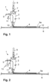
- Fig. 2 A variant is shown in which the nozzle 1 basically has the same structure as in Fig.1 , but an additional drive device 13 is provided for driving the cable 5.
- the drive device 13 comprises an electric motor, a driven roller and a passively rotating roller, wherein the driven roller is driven by the electric motor and the cable 5 is guided between the two rollers.
- the drive device 13 is mounted in front of the nozzle body 2 so that the cable 5 is driven into the nozzle body interior 3.
- a design at the outlet from the nozzle body 2 is also possible in order to pull the cable 5 out of the nozzle body interior 4 with the aid of the drive device.
- the drive device 13 can be attached to the nozzle body 2 or to a device holding the nozzle body 2.
- the speed at which the cable 5 is driven by the drive device 13 corresponds in particular to the relative speed between the nozzle 1 and the material layer 6. This ensures a continuous, uniform exit of the cable 5 and elastomer 4 via the outlet opening 10 in the lower area of the nozzle 1.
- the cable 5 can be applied to the material layer 6 without stretching or compressing. Furthermore, it is advantageous that there is no need to fix the cable 5 to the material layer 6 or to a device supporting the material layer 6.
- Fig.3 the material layer 6 with applied, caterpillar-shaped elastomer and cable 5 accommodated therein is shown in an enlarged view.
- the cable protrudes on both sides of the elastomer 4 with cable ends 5a, 5b, which are thus bare and free of elastomer and can be used for connection to a sensor, an electrode or an evaluation unit or signal generation unit.
- Fig.4 shows a longitudinal section through the cable 5, which consists of a rubber core or a rubber core 14 and an enveloping metal mesh 15.
- the metal mesh 15 is designed as a wire mesh that is electrically conductive and can transmit electrical signals.
- the inner rubber core 14 can be greatly stretched and retracts to its original state after linear-elastic stretching.
- the metal mesh 15 in the form of the wire mesh can also exert corresponding stretches and is returned to its retracted original state either due to its own elastic behavior or via the rubber core 14 after external forces are removed.
- the linear elastic elongation of the cable 5 is at least 60% and thus 1.6 times higher than the unstretched initial state.
- a nozzle 1 is shown in a variant in which a tubular cable guide part 16 is integrated into the nozzle body 2 of the nozzle 1, through which the cable 5 is guided.
- the cable guide part is guided through the nozzle body interior 3.
- the feed opening 8, through which the cable 5 is guided into the cable guide part 16, is located at a front end of the cable guide part 16 in the side area of the nozzle body 2.
- the lower end of the curved cable guide part 16 projects into the outlet opening 10 of the nozzle 1, with the outlet opening 17 of the cable guide part 16 lying in the outlet opening 10 of the nozzle 1.
- the elastomer can exit via the annular area between the outer wall of the cable guide part 16 and the inner wall of the outlet opening 10.
- the cable guide part 16 is formed in one piece with the nozzle body 2.
Landscapes
- Engineering & Computer Science (AREA)
- Health & Medical Sciences (AREA)
- Mechanical Engineering (AREA)
- Manufacturing & Machinery (AREA)
- Materials Engineering (AREA)
- Chemical & Material Sciences (AREA)
- Heart & Thoracic Surgery (AREA)
- Animal Behavior & Ethology (AREA)
- General Health & Medical Sciences (AREA)
- Public Health (AREA)
- Veterinary Medicine (AREA)
- Life Sciences & Earth Sciences (AREA)
- Vascular Medicine (AREA)
- Biomedical Technology (AREA)
- Physics & Mathematics (AREA)
- Optics & Photonics (AREA)
- Textile Engineering (AREA)
- Treatment Of Fiber Materials (AREA)
- Laminated Bodies (AREA)
Description
- Die Erfindung bezieht sich auf ein Verfahren zum Aufbringen von Elastomer und einem in das Elastomer eingebetteten Kabel auf eine Stofflage eines Bekleidungsstücks oder einer Bandage.
- Aus der
EP 3 172 977 A1 ist ein Verfahren zur Herstellung von Bekleidungsstücken oder Bandagen bekannt, bei dem eine Stofflage des Bekleidungsstücks bzw. der Bandage mit einem Verbund von Elastomer und Verstärkungsmaterial verbunden wird. Hierbei wird auf eine Elastomerschicht das Verstärkungsmaterial im flüssigen oder weichen, verformbaren Zustand aufgetragen, das nach dem Auftragen aushärtet. Die Elastomerschicht und das Verstärkungsmaterial werden über jeweils eine Düse aufgetragen, wobei die Düse für das Verstärkungsmaterial als ein 3D-Druckkopf ausgebildet ist. - Aus der
US 2017/0151770 A1 ist es bekannt, mithilfe eines Druckkopfes schichtweise Elastomer auf eine Stofflage aufzubringen. - Aus der
DE 10 2018 104 774 B3 ist eine auf der Haut tragbare Elektrode bekannt, die in ein Bekleidungsstück oder in eine Bandage integriert ist. Die Elektrode umfasst eine elektrisch leitende Hautkontaktschicht, die über einen elektrisch leitenden Klettverschluss mit einem Stromanschluss zu verbinden ist. - In der
DE 10 2020 200 508 A1 wird ein Druckkopf für ein Drucksystem zur additiven Herstellung eines Faserverbundbauteils beschrieben. Der Druckkopf umfasst einen ersten Zufuhrabschnitt zum Zuführen von strangförmigem Thermoplastmaterial in den Druckkopf und einen zweiten Zufuhrabschnitt zum Zuführen von strangförmigem Fasermaterial oder Leitermaterial als Kernmaterial in den Druckkopf. Desweiteren sind eine Heizeinrichtung zum Plastifizieren des durch den ersten Zufuhrabschnitt zugeführten Thermoplastmaterials und eine Schneideinrichtung zum Durchtrennen des durch den zweiten Zufuhrabschnitt zugeführten Kernmaterials vorgesehen. Über eine Düse des Druckkopfes, die einen Extrusionskanal bildet, wird das Kernmaterial in das Thermoplastmaterial eingebettet. - Die
US 2015/0 165 666 A1 offenbart eine Vorrichtung mit einer Düse zum Koextrudieren eines Polymerfadens und eines Faserfadens. - Die
EP 3 130 444 A1 beschreibt einen 3D-Drucker, bei dem ein Verstärkungsfilament mit einem Kern und einem den Kern umgebenden Matrixmaterial in eine Extrusionsdüse eingeführt wird. - Aus der
EP 0 187 270 A1 ist ein Verfahren zum Fixieren eines elastischen Bandes oder einer elastischen Folie auf flächigen Materialien bekannt. Durch Koextrusion oder sukzessive Extrusion wird ein Produkt hergestellt, das aus einer Hotmeltschicht und einer Schicht aus einem thermoplastischen Elastomermaterial besteht. - In der
DE 197 44 527 A1 wird die Herstellung eines isolierten elektrischen Leiters im Extrusionsverfahren beschrieben. Die Extrusion erfolgt durch ineinandergesetzte, innere und äußere Düsen. - Die
WO 2017/091154 A1 offenbart, einen elektrischen Leiter abschnittsweise mit einer Isolierung zu versehen, so dass der Leiter sich aus isolierten und aus nicht-isolierten Abschnitten zusammensetzt. Dieses Dokument offenbart auch ein Verfahren mit den Merkmalen des Oberbegriffs des Anspruchs 1. - Die
US 2019/0009472 A1 offenbart eine Düse zum Auftragen eines Leiters 1502 und von Beschichtungsmaterial, das nach dem Beenden des Auftragungsvorgangs den Leiter einhüllt. Bei dem Beschichtungsmaterial handelt es sich um ein isolierendes Kunststoffmaterial. - Der Erfindung liegt die Aufgabe zugrunde, auf einfache und effiziente Weise Elastomer und ein in das Elastomer eingebettetes Kabel auf eine Stofflage eines Bekleidungsstücks oder einer Bandage aufzubringen.
- Diese Aufgabe wird erfindungsgemäß mit den Merkmalen des unabhängigen Anspruchs 1 gelöst. Die abhängigen Ansprüche geben zweckmäßige Weiterbildungen an.
- Mithilfe des erfindungsgemäßen Verfahrens kann in einem einzigen Verfahrensschritt Elastomer und ein Kabel auf eine Stofflage eines Bekleidungsstücks oder einer Bandage in der Weise aufgebracht werden, dass das Kabel teilweise oder vollständig von dem Elastomer umhüllt ist. Das Verfahren wird mithilfe einer Düse durchgeführt, die sowohl für das Auftragen des Elastomers als auch für das Auftragen des Kabels auf die Stofflage ausgebildet ist. Hierbei wird das Elastomer im verformbaren Zustand über die Düse aufgetragen und gleichzeitig auch das Kabel über diese Düse auf die Stofflage aufgetragen. Es genügt somit lediglich eine einzige Düse für den Auftrag sowohl von Elastomer als auch des Kabels. Das Kabel wird in eine Elastomerbahn auf der Stofflage gelegt, die von dem aus der Düse austretenden Elastomer erzeugt wird. Der Ausstoß von Elastomer und Kabel aus der gemeinsamen Düse erfolgt zeitgleich.
- Nach Abschluss des Verfahrensschrittes ist es grundsätzlich nicht erforderlich, eine weitere Behandlung oder einen weiteren Verfahrensschritt durchzuführen. Das Kabel ist von dem Elastomer zumindest teilweise umhüllt, wodurch zum einen eine sichere und feste Verbindung zwischen dem Kabel und der Stofflage erreicht wird und zum andern das Kabel vor äußeren Einflüssen, beispielsweise Feuchtigkeit geschützt ist. Die Verbindung zwischen dem Elastomer und der Stofflage erfolgt dadurch, dass das Elastomer im verformbaren bzw. weichen, fließfähigen Zustand auf die Stofflage aufgetragen wird, so dass das Elastomer in die Stofflage eindringen kann. Nach dem Aushärten ist das Elastomer fest mit der Stofflage verbunden.
- Bei dem Bekleidungsstück, das als Bestandteil die Stofflage aufweist, handelt es sich beispielsweise um ein Unterbekleidungsstück oder um ein Oberbekleidungsstück wie beispielsweise ein Hemd, ein T-Shirt, eine Hose wie zum Beispiel eine Sporthose, einen Büstenhalter oder dergleichen. Des Weiteren kommt auch ein Gürtel, ein Brustgurt oder eine Manschette in Betracht, die zum Beispiel über das Handgelenk oder das Fußgelenk gestülpt wird; auch derartige Gegenstände zählen im Sinne der Erfindung als Bekleidungsstück. Die Stofflage kann auch Bestandteil einer Bandage sein, insbesondere einer Gelenkbandage wie beispielsweise einer Kniebandage oder einer Ellbogenbandage.
- Das Kabel ist vorteilhafterweise elektrisch leitfähig ausgebildet und dementsprechend in der Lage, elektrische Signale zu übertragen. Dies ermöglicht es, beispielsweise Elektroden oder Sensoren in das Bekleidungsstück bzw. die Bandage zu integrieren, wobei elektrische Signale von dem Sensor bzw. der Elektrode über das Kabel, welches an den Sensor bzw. die Elektrode angeschlossen ist, zu einer Auswerteeinheit übertragen werden können, in der die elektrischen Signale einer Auswertung unterzogen werden. Mithilfe des Sensors bzw. der Elektrode werden beispielsweise Vitalparameter des Körpers anhand von Spannungsänderungen der Haut oder einer Änderung des elektrischen Hautwiderstandes ermittelt. Umgekehrt ist es auch möglich, die Elektrode bzw. den Sensor als Signalgeber einzusetzen, über den elektrische Impulse, die in einem Impulsgeber erzeugt werden, auf die Haut übertragen werden, beispielsweise zur Muskelstimulation.
- Gemäß einer weiteren vorteilhaften Ausführung treten das Elastomer und das Kabel über die gleiche Düsenöffnung aus der Düse aus. Es genügt somit grundsätzlich, dass die Düse nur eine Austrittsöffnung aufweist, über die sowohl das Elastomer als auch das Kabel austreten. Diese Ausführung hat den Vorteil, dass das Kabel bereits mit dem Austreten aus der Düsenöffnung zumindest teilweise von dem Elastomer umhüllt ist und bei einer Relativbewegung zwischen Düse und Stofflage eine Elastomerbahn mit integriertem Kabel erzeugt wird.
- Alternativ ist es auch möglich, eine gemeinsame Düse für Kabel und Elastomer vorzusehen, die jedoch zwei Austrittsöffnungen besitzt, von denen eine Austrittsöffnung dem Kabel und die zweite Austrittsöffnung dem Elastomer zugeordnet sind. In diesem Fall treten das Kabel und das Elastomer über unterschiedliche Düsenöffnungen aus, die jedoch in der Weise angeordnet sein können, dass das Kabel in gewünschter Weise in das Elastomer auf der Stofflage eingebettet wird. Vorteilhafterweise ist die Austrittsöffnung für das Elastomer in Verfahrrichtung der Düse der Austrittsöffnung für das Kabel vorgelagert, so dass in Verfahrrichtung zuerst das Elastomer und darauffolgend das Kabel ausgebracht werden.
- Mithilfe des Verfahrens kann gleichzeitig Elastomer und das Kabel aus der Düse austreten. Dieser Vorgang wird phasenweise durchgeführt. Das Kabel wird in einer weiteren Phase ohne Elastomer über die Düse auf die Stofflage aufgetragen. Dementsprechend wird das Ausbringen von Elastomer gestoppt, indem beispielsweise die Elastomerzufuhr zu der Düse unterbrochen wird. Das alleinige Ausbringen des Kabels aus der Düse hat den Vorteil, dass ein Kabelabschnitt frei von Elastomer auf der Stofflage aufliegt oder sich mit geringem Abstand zu der Stofflage befindet, so dass dieser Abschnitt an eine elektrische Baueinheit angeschlossen werden kann, insbesondere dem Sensor bzw. der Elektrode oder einer Auswerteeinheit. Es ist insbesondere möglich, zwei gegenüberliegende Enden des Kabels frei von Elastomer zu belassen, so dass ein Ende mit dem Sensor bzw. der Elektrode und das gegenüberliegende Ende mit der Auswerteeinheit verbunden werden können. Indem die Phase, in der nur das Kabel, jedoch kein Elastomer über die Düse aufgebracht wird, am Beginn oder am Ende eines Arbeitsschrittes liegt, genügt es, nur einen einzigen Arbeitsschritt mit einer Relativbewegung zwischen Kabel und Stofflage vorzusehen, um das Kabel phasenweise mit Elastomer auszubringen, so dass das Kabel vom Elastomer umhüllt ist, und phasenweise nur das Kabel, jedoch kein Elastomer auszubringen, so dass ein oder mehrere Abschnitte des Kabels frei von Elastomer liegen.
- Dementsprechend weist das erfindungsgemäße Verfahren, bei dem Elastomer und ein in das Elastomer eingebettetes Kabel auf eine Stofflage eines Bekleidungsstücks oder einer Bandage aufgebracht wird, die folgenden Verfahrensschritte auf:
- das Elastomer wird mithilfe einer Düse im verformbaren Zustand auf die Stofflage aufgetragen,
- das Kabel wird über die gleiche Düse phasenweise gleichzeitig mit dem Elastomer in der Weise auf die Stofflage aufgetragen, dass das Elastomer das Kabel zumindest teilweise umhüllt,
- in einer anderen Phase wird nur das Kabel, jedoch kein Elastomer über die Düse auf die Stofflage aufgetragen.
- Somit bezieht sich die Erfindung auf ein Verfahren zum Aufbringen von Elastomer und einem in das Elastomer eingebetteten Kabel auf eine Stofflage eines Bekleidungsstücks oder einer Bandage, wobei das Elastomer mithilfe einer Düse im verformbaren Zustand auf die Stofflage aufgetragen wird und das Kabel über die gleiche Düse phasenweise gleichzeitig mit dem Elastomer in der Weise auf die Stofflage aufgetragen wird, dass das Elastomer das Kabel zumindest teilweise umhüllt. In einer anderen, weiteren Phase wird nur das Kabel, jedoch kein Elastomer über die Düse auf die Stofflage aufgetragen. Ein aus der Düse bereits ausgetretenes Kabelende wird relativ zur Stofflage fixiert. Die Fixierung kann entweder unmittelbar auf der Stofflage erfolgen oder an einem ortsfesten Gegenstand, beispielsweise einem Tisch, auf dem die Stofflage aufliegt. Die Fixierung des aus der Düse ausgetretenen Kabelendes erfolgt vor dem Arbeitsschritt mit zumindest phasenweise gleichzeitigem Auftragen von Elastomer und Kabel. Aufgrund der Fixierung kann bei einer Relativbewegung zwischen Düse und Stofflage das Kabel aus der Düsenöffnung in der Düse herausgezogen werden, sobald beispielsweise die Düse sich über die Stofflage bewegt. Diese Vorgehensweise hat den Vorteil, dass auf eine Antriebseinrichtung zum Antreiben des Kabels verzichtet werden kann.
- Zusätzlich ist es auch möglich, dass das Kabel mithilfe einer Antriebseinrichtung mit einer Geschwindigkeit angetrieben wird, die der Relativgeschwindigkeit zwischen der Düse und der Stofflage entspricht. Die Antriebseinrichtung kann entweder der Düse vorgelagert sein, bevor das Kabel mit Antrieb in die Düse hineingeführt wird, oder der Düse nachgeordnet sein, so dass das Kabel mithilfe der Antriebseinrichtung aus der Düse herausgezogen wird. Die Antriebseinrichtung hat den Vorteil, dass, in einer nicht beanspruchten Ausführungsform, das aus der Düse bereits ausgetretene Kabelende nicht fixiert werden muss.
- Gemäß noch einer weiteren vorteilhaften Ausführung ist das verwendete Kabel in Kabellängsrichtung elastisch ausgebildet und weist eine verhältnismäßig hohe Elastizität auf, insbesondere in der Weise, dass das Kabel auf das mindestens 1.6fache elastisch dehnbar ist. Erst bei Dehnungen, die größer sind als das 1.6fache, wird der linear-elastische Bereich des Kabels verlassen. Bis zu dieser Dehnung jedoch ist ein linearelastisches Verhalten des Kabels bei einer Dehnung in Kabellängsrichtung gewährleistet. Die Elastizität des Kabels erlaubt es, dass Stoffdehnungen auch von dem Kabel mit ausgeführt werden können, wodurch das Traggefühl des Bekleidungsstücks oder der Bandage, das bzw. die mit dem Kabel versehen ist, nicht beeinträchtigt wird. Stoffdehnungen können auch von dem Elastomer mit ausgeführt werden, mit dem das Kabel zumindest teilweise umhüllt ist und das das Kabel an der Stofflage hält.
- Die Umhüllung des Kabels durch das Elastomer erfolgt vorzugsweise derart, dass das Kabel auf der der Stofflage abgewandten Seite vollständig von Elastomer bedeckt ist. Das Kabel kann gegebenenfalls unmittelbar auf der Stofflage aufliegen. Alternativ ist es auch möglich, dass das Kabel ringsum von Elastomer umhüllt ist, also auch auf der der Stofflage zugewandten Seite.
- Gemäß einer weiteren vorteilhaften Ausführung wird ein elastisches Kabel verwendet, das aus einem Gummikern und einem umhüllenden Metallnetz besteht. Der Gummikern ist Träger des umhüllenden Metallnetzes und erlaubt eine elastische Dehnung in Längsrichtung. Das Metallnetz, welches den Gummikern umhüllt, ist elektrisch leitfähig und ermöglicht eine elektrische Signalübertragung, wobei zugleich die Stabilität des Kabels durch das Metallnetz verbessert ist. Bei einer Dehnung in Kabellängsrichtung wird auch das Metallnetz gedehnt. Sobald sich der Gummikern wieder elastische zusammenzieht, wird auch das Metallnetz wieder zusammengezogen.
- Als Elastomer wird beispielsweise ein thermoplastisches Elastomer verwendet, das bei Erwärmung weich oder flüssig wird und mit dem Abkühlen aushärtet. Im erwärmten Zustand kann das Elastomer über die Düse aufgetragen werden, woraufhin das Elastomer aushärtet und hierbei die feste Verbindung mit der Stofflage eingeht und außerdem das Kabel schützt und an der Stofflage sichert. Im ausgehärteten Zustand besitzt das Elastomer ein elastisches Verhalten. Als Elastomer kann zum Beispiel ein Silikon verwendet werden.
- Optional wird auf das Elastomer nach dem Auftragen auf die Stofflage und im noch nicht ausgehärteten Zustand ein Beflockungsmaterial aufgebracht, wodurch das Tragegefühl verbessert werden kann. Das Beflockungsmaterial ist in der Lage, Feuchtigkeit aufzunehmen.
- Es wird auch ein Bekleidungsstück oder eine Bandage mit einer Stofflage beschrieben, die Träger eines Kabels ist, welches mithilfe von Elastomer mit der Stofflage verbunden ist. Das Kabel ist in der vorbeschriebenen Weise ausgebildet, vorzugsweise elektrisch leitfähig und in Kabellängsrichtung elastisch. Das Bekleidungsstück bzw. die Bandage wird vorteilhafterweise nach dem vorbeschriebenen Verfahren hergestellt.
- Mindestens ein Kabelende, vorzugsweise beide Kabelenden liegen frei von Elastomer, wobei der zwischen den Kabelenden liegende Kabelabschnitt mit Elastomer bedeckt ist. In dieser Ausführung ist das Kabel fest mit der Stofflage verbunden, zugleich kann zumindest ein Kabelende, vorzugsweise beide Kabelenden, beispielsweise mit einem Sensor oder einer Elektrode und einer Auswerteeinheit oder einer Signalerzeugungseinheit verbunden werden. Bei dem Bekleidungsstück handelt es sich vorteilhafterweise um ein vorbeschriebenes Bekleidungsstück, gleiches gilt für die Bandage.
- Das Elastomer und das Kabel können sowohl auf der dem Körper zugewandten Innenseite des Bekleidungsstücks als auch auf der dem Körper abgewandten Außenseite des Bekleidungsstücks angeordnet sein.
- Eine Düse zum gemeinsamen Auftragen von Elastomer und Kabel auf eine Gewebelage wird ebenfalls beschrieben. Das Bekleidungsstück bzw. die Bandage wird nach dem vorbeschriebenen Verfahren unter Verwendung der Düse hergestellt. Die Düse weist einen Düsenkörper auf, in den zwei Zufuhröffnungen eingebracht sind, von denen eine erste Zufuhröffnung für die Zufuhr von Elastomer und die zweite Zufuhröffnung für die Zufuhr des Kabels dienen. Gegebenenfalls können das Elastomer und das Kabel über eine gemeinsame Zufuhröffnung zugeführt werden.
- Das Elastomer und das Kabel können über die gemeinsame Düse gleichzeitig oder zeitlich versetzt auf die Stofflage aufgetragen werden.
- Der Düsenkörper weist einen Düsenkörperinnenraum auf, in den die erste und die zweite Zufuhröffnung münden. Außerdem weist die Düse eine gemeinsame Austrittsöffnung sowohl für das Elastomer als auch für das Kabel auf. Möglich ist auch eine Ausführung mit jeweils einer Austrittsöffnung für Elastomer und das Kabel. Innerhalb des Düsenkörperinnenraums gelangt das Kabel in Kontakt mit dem Elastomer und wird von dem Elastomer benetzt. Wenn das unter Druck stehende Elastomer über die Austrittsöffnung aus der Düse austritt, wird durch die Haftung des Kabels an das Elastomer auch das Kabel mit einer Kraft aus der Austrittsöffnung der Düse hinausbewegt. Diese Kraft kann ausreichend sein, um einen kontinuierlichen Austritt des Kabels aus der Düse zu bewerkstelligen.
- Es kann sich an oder in der Düse eine Antriebseinrichtung für das Kabel finden, welche das Kabel antreibt, wobei je nach Positionierung der Antriebseinrichtung entweder das Kabel in die Düse hineinbefördert oder aus der Düse herausgezogen wird.
- Es kann in den Düsenkörper der Düse ein röhrenförmiges Kabelführungsteil integriert sein, durch das das Kabel geführt ist. Das Kabelführungsteil ist durch den Düsenkörperinnenraum geführt und stellt sicher, dass der Kontakt zwischen dem Elastomer und dem Kabel erst nach dem Austritt aus der Düse erfolgt. Dies hat den Vorteil, dass das Kabel innerhalb der Düse nicht am Elastomer haftet und das Ausbringen des Kabels aus der Düse ungehindert vom Elastomer und mit geringen Vorschubkräften erfolgt. Die Austrittsöffnung des Kabelführungsteils liegt zweckmäßigerweise in oder benachbart zu der Austrittsöffnung der Düse.
- Das Ende des röhrenförmigen Kabelführungsteils kann in die Austrittsöffnung hineinragen. Das Kabelführungsteil ist vorteilhafterweise einteilig mit dem Düsenkörper ausgebildet.
- Weitere Vorteile und zweckmäßige Ausführungen sind den weiteren Ansprüchen, der Figurenbeschreibung und den Zeichnungen zu entnehmen. Es zeigen:
- Fig. 1
- einen Schnitt durch eine Düse zum gemeinsamen Auftrag von Elastomer und einem Kabel auf eine Stofflage,
- Fig. 2
- die Düse gemäß
Fig. 1 , jedoch mit einer zusätzlichen Antriebseinrichtung zum Antreiben des Kabels durch die Düse, - Fig. 3
- in vergrößerter Darstellung die Stofflage mit Elastomer und Kabel,
- Fig. 4
- einen Schnitt durch ein elektrisch leitfähiges Kabel,
- Fig. 5
- einen Schnitt durch eine Düse zum gemeinsamen Auftrag von Elastomer und einem Kabel in einer weiteren Ausführung.
- In den Figuren sind gleiche Bauteile mit gleichen Bezugszeichen versehen.
- In
Fig. 1 ist eine Düse 1 dargestellt, die einen Düsenkörper 2 aufweist, wobei über den Düsenkörperinnenraum 3 im Düsenkörper 2 ein darin befindliches Elastomer 4 und ein Kabel 5 auf eine Stofflage 6 aufgetragen werden können. Die Stofflage 6 liegt vorzugsweise horizontal auf einem Arbeitstisch auf. Die Düse 1 wird mithilfe einer geeigneten Düsenvorrichtung über die Oberseite der Stofflage 6 hinwegbewegt, und zugleich werden das Elastomer 4 und das Kabel 5 aus der Düse 1 ausgebracht und auf die Oberseite der Stofflage 6 aufgetragen. - Das Kabel 5 ist vorzugsweise ein elektrisch leitfähiges Kabel, das zur elektrischen Signalübertragung eingesetzt wird. Das Kabel 5 ist mithilfe des Elastomers 4 fest mit der Stofflage 6 verbunden. Das Kabel 5 wird insbesondere von dem Elastomer 4 umhüllt und ist hierdurch vor äußeren Einflüssen wie beispielsweise Feuchtigkeit geschützt. Das Kabel 5 ist vorteilhafterweise längselastisch ausgebildet und besitzt insbesondere eine Elastizität, gemäß der das Kabel 5 auf das mindestens 1.6fache linear-elastisch dehnbar ist. Mithilfe des Kabels 5 können beispielsweise elektrische Signale zwischen einer Elektrode oder einem Sensor, die bzw. der in die Stofflage 6 integriert ist, und einer Auswerteeinheit oder einer Signalerzeugungseinheit übertragen werden. Über den Sensor bzw. die Elektrode können zum Beispiel Vitalparameter einer Person aufgenommen werden, welche ein Bekleidungsstück und eine Bandage mit der gezeigten Stofflage 6 trägt. Es ist auch möglich, über das Kabel 5 Stromimpulse auf eine Elektrode in der Stofflage 6 zu übertragen, über die einzelne Muskelpartien gezielt stimuliert werden.
- Bei dem Bekleidungsstück, in das die Stofflage 6 integriert wird, handelt es sich beispielsweise um ein Sportbekleidungsstück wie ein T-Shirt oder eine Sporthose. Im Fall einer Bandage, in die die Stofflage 6 integriert wird, handelt es sich insbesondere um eine manschettenförmige Gelenkbandage, zum Beispiel eine Kniebandage oder eine Ellbogenbandage.
- An dem Düsenkörper 2 befindet sich eine erste, obenliegende Zufuhröffnung 7 für die Zufuhr des Elastomers 4 über eine Zufuhrleitung 9. In die Seitenwand des Düsenkörpers 2 ist eine zweite Zufuhröffnung 8 eingebracht, über die das Kabel 5 in den Düsenkörperinnenraum 3 eingeleitet wird. Der Düsenkörper 2 verjüngt sich nach unten hin, wobei an der untenliegenden Spitze des Düsenkörpers 2 eine gemeinsame Austrittsöffnung 10 für den Austritt von Elastomer 4 und Kabel 5 angeordnet ist.
- Über die Zufuhrleitung 9 wird unter Druck stehendes, fließfähiges Elastomer 4 in den Düsenkörperinnenraum 3 eingeleitet, in den auch über die zweite Zufuhröffnung 8 im Seitenbereich des Düsenkörpers 2 das Kabel 5 eingeführt wird. Im Düsenkörperinnenraum 3 haftet sich das Elastomer 4 an das Kabel 5 an, woraufhin Elastomer 4 und das Kabel 5 gemeinsam über die untenliegende Austrittsöffnung 10 austreten und auf die Oberseite der Stofflage 6 aufgebracht werden. Die Zufuhrrichtungen von Elastomer durch die Zufuhrleitung 9 und des Kabels 5 seitlich in den Düsenkörperinnenraum 3 hinein sind jeweils mit Pfeilen gekennzeichnet.
- Die Düse 1 wird in der Weise über die Stofflage 6 geführt, dass die untenliegende Austrittsöffnung 10 einen kleinen Abstand zur Oberseite der Stofflage 6 aufweist. Die Düse 1 befindet sich vorteilhafterweise an einer Vorrichtung, mittels der die Düse 1 horizontal in Pfeilrichtung 11 über die feststehende Stofflage 6 bewegt wird. Beim Austritt aus der Austrittsöffnung 10 bildet sich eine Raupe auf der Oberseite der Stofflage 6, bestehend aus Elastomer 4 und Kabel 5, das vorzugweise vollständig von dem Elastomer 4 umhüllt ist. Das Elastomer 4 wird im fließfähigen Zustand aufgebracht und kann in die Poren der Stofflage 6 eindringen. Nach dem Aushärten ist eine feste Verbindung von Elastomer 4 einschließlich dem Kabel 5 mit der Stofflage 6 gegeben.
- Das Kabelende 5a des Kabels 5 wird zu Beginn eines Arbeitsschrittes, nachdem es durch die Düse 2 durchgezogen wurde und über die Austrittsöffnung 10 ausgetreten ist, ohne Elastomer 4 an der Stofflage 6 oder einem Arbeitstisch, auf dem die Stofflage 6 aufliegt, fixiert. Hierzu ist ein Fixierelement 12 vorgesehen, beispielsweise eine Klammer oder dergleichen, das an dem Kabelende 5 angreift. Sobald die Düse 2 in Pfeilrichtung 11 über die Stofflage 6 bewegt wird, wird das Kabel 5 aufgrund seiner Befestigung über das Fixierelement 12 in den Düsenkörper 2 hineingezogen und über die Austrittsöffnung 10 herausgezogen.
- Das von Elastomer 4 freie Kabelende 5a eignet sich zum Anschluss beispielsweise an einen Sensor, an eine Elektrode oder auch eine Auswerteeinheit oder Signalerzeugungseinheit.
- In entsprechender Weise kann ein gegenüberliegendes, zweites Kabelende auch frei von Elastomer gehalten werden. Die Elastomerzufuhr wird hierfür kurz unterbrochen.
- Das Elastomer 4 wird insbesondere im erwärmten, fließfähigen Zustand und unter Druck über die Zufuhrleitung 9 in den Düsenkörperinnenraum 3 und weiter über die Austrittsöffnungen 10 auf die Stofflage 6 aufgebracht. Mit dem Abkühlen härtet das Elastomer 4 aus, wobei auch im ausgehärteten Zustand ein elastisches Verhalten des Elastomers gegeben ist. Auch das Kabel 5 ist elastisch ausgebildet, so dass sich die Stofflage auch nach dem Auftragen von Elastomer 4 und Kabel 5 elastisch dehnen und wieder zusammenziehen kann.
- In
Fig. 2 ist eine Ausführungsvariante dargestellt, in der die Düse 1 grundsätzlich den gleichen Aufbau wie beiFig. 1 aufweist, jedoch eine zusätzliche Antriebseinrichtung 13 zum Antreiben des Kabels 5 vorgesehen ist. Die Antriebseinrichtung 13 umfasst einen Elektromotor, eine angetriebene Rolle und eine passiv mitdrehende Rolle, wobei die angetriebene Rolle von dem Elektromotor angetrieben wird und das Kabel 5 zwischen den beiden Rollen hindurchgeführt ist. Die Antriebseinrichtung 13 ist im Düsenkörper 2 vorgelagert, so dass das Kabel 5 mit Antrieb in den Düsenkörperinnenraum 3 hineinbefördert wird. Grundsätzlich möglich ist auch eine Ausbildung am Austritt aus dem Düsenkörper 2, um das Kabel 5 mithilfe der Antriebseinrichtung aus dem Düsenkörperinnenraum 4 herauszuziehen. Die Antriebseinrichtung 13 kann an dem Düsenkörper 2 oder einer den Düsenkörper 2 haltenden Vorrichtung befestigt werden. - Die Geschwindigkeit, mit der das Kabel 5 von der Antriebseinrichtung 13 angetrieben wird, entspricht insbesondere der Relativgeschwindigkeit zwischen Düse 1 und Stofflage 6. Dies stellt einen kontinuierlichen, gleichmäßigen Austritt von Kabel 5 und Elastomer 4 über die Austrittsöffnung 10 im unteren Bereich der Düse 1 sicher. Das Kabel 5 kann hierbei ohne Dehnungen oder Stauchungen auf die Stofflage 6 aufgetragen werden. Des Weiteren ist es vorteilhaft, dass auf eine Fixierung des Kabels 5 an der Stofflage 6 oder einer die Stofflage 6 tragenden Vorrichtung verzichtet werden kann.
- In
Fig. 3 ist die Stofflage 6 mit aufgebrachtem, raupenförmigem Elastomer und darin aufgenommenem Kabel 5 in vergrößerter Darstellung gezeigt. Zu beiden Seiten des Elastomers 4 ragt das Kabel mit Kabelenden 5a, 5b heraus, die somit blank und frei von Elastomer liegen und zum Anschluss an einen Sensor, einer Elektrode oder einer Auswerteeinheit oder Signalerzeugungseinheit genutzt werden können. -
Fig. 4 zeigt einen Längsschnitt durch das Kabel 5, das aus einem Gummikern oder einer Gummiseele 14 und einem umhüllenden Metallnetz 15 besteht. Das Metallnetz 15 ist als ein Drahtgeflecht ausgebildet, das elektrisch leitend ist und elektrische Signale übertragen kann. Der innenliegende Gummikern 14 kann stark gedehnt werden und zieht sich nach linear-elastischer Dehnung wieder in den Ausgangszustand zurück. Das Metallnetz 15 in Form des Drahtgeflechts kann ebenfalls entsprechende Dehnungen ausüben und wird entweder aufgrund eines eigenen elastischen Verhaltens oder über den Gummikern 14 nach Wegfall äußerer Kräfte wieder in den zurückgezogenen Ausgangszustand gebracht. - Die linear-elastische Dehnung des Kabels 5 beträgt mindestens 60 % und somit das 1.6fache gegenüber dem ungedehnten Ausgangszustand.
- In
Fig. 5 ist eine Düse 1 in einer Ausführungsvariante dargestellt, bei der in den Düsenkörper 2 der Düse 1 ein röhrenförmiges Kabelführungsteil 16 integriert ist, durch das das Kabel 5 geführt ist. Das Kabelführungsteil ist durch den Düsenkörperinnenraum 3 geführt. Die Zufuhröffnung 8, über die das Kabel 5 in das Kabelführungsteil 16 hineingeführt wird, befindet sich an einem vorderen Ende des Kabelführungsteil 16 im Seitenbereich des Düsenkörpers 2. Das untere Ende des gekrümmt ausgeführten Kabelführungsteils 16 ragt in die Austrittsöffnung 10 der Düse 1 hinein, wobei die Austrittsöffnung 17 des Kabelführungsteils 16 in der Austrittsöffnung 10 der Düse 1 liegt. Das Elastomer kann über den ringförmigen Bereich zwischen der Außenwand des Kabelführungsteils 16 und der Innenwand der Austrittsöffnung 10 austreten. - Das Kabelführungsteil 16 ist einteilig mit dem Düsenkörper 2 ausgebildet.
Claims (7)
- Verfahren, bei dem Elastomer (4) und ein in das Elastomer (4) eingebettetes Kabel (5) auf eine Stofflage (6) eines Bekleidungsstücks oder einer Bandage aufgebracht werden, gekennzeichnet durch die folgenden Verfahrensschritten:- das Elastomer (4) wird mithilfe einer Düse (1) im verformbaren Zustand auf die Stofflage (6) aufgetragen,- das Kabel (5) wird über die gleiche Düse (1) phasenweise gleichzeitig mit dem Elastomer (4) in der Weise auf die Stofflage (6) aufgetragen, dass das Elastomer (4) das Kabel (5) zumindest teilweise umhüllt,- in einer anderen Phase wird nur das Kabel (5), jedoch kein Elastomer (4) über die Düse (1) auf die Stofflage (6) aufgetragen,wobei ein aus der Düse (1) bereits ausgetretenes Kabelende (5a, 5b) relativ zur Stofflage (6) fixiert wird,wobei die Fixierung des aus der Düse (1) ausgetretenen Kabelendes (5a, 5b) vor dem Arbeitsschritt mit zumindest phasenweise gleichzeitigem Auftragen von Elastomer (4) und Kabel (5) erfolgt.
- Verfahren nach Anspruch 1,
dadurch gekennzeichnet,
dass das Elastomer (4) und das Kabel (5) über die gleiche Düsenöffnung aus der Düse (1) austreten. - Verfahren nach Anspruch 1 oder 2,
dadurch gekennzeichnet,
dass die andere Phase, in der nur das Kabel (5), jedoch kein Elastomer (4) über die Düse (1) auf die Stofflage (6) aufgebracht wird, am Beginn oder am Ende eines Arbeitsschrittes liegt, in welchem das Kabel (5) aus der Düse (1) austritt. - Verfahren nach einem der Ansprüche 1 bis 5,
dadurch gekennzeichnet,
dass das Kabel (5) mithilfe einer Antriebseinrichtung (13) mit einer Geschwindigkeit angetrieben wird, die der Relativgeschwindigkeit zwischen der Düse (1) und Stofflage (6) entspricht. - Verfahren nach einem der Ansprüche 1 bis 4,
dadurch gekennzeichnet,
dass das Kabel (5) elastisch ausgebildet ist und eine Elastizität aufweist, gemäß der das Kabel (5) auf das mindestens 1.6fache elastisch dehnbar ist. - Verfahren nach einem der Ansprüche 1 bis 5,
dadurch gekennzeichnet,
dass ein elastisches Kabel (5) verwendet wird, das aus einem Gummikern (14) und einem umhüllenden Metallnetz (15) besteht. - Verfahren nach einem der Ansprüche 1 bis 6,
dadurch gekennzeichnet,
dass das Kabel (5) elektrisch leitfähig ausgebildet ist.
Applications Claiming Priority (2)
| Application Number | Priority Date | Filing Date | Title |
|---|---|---|---|
| DE102022109327.1A DE102022109327A1 (de) | 2022-04-14 | 2022-04-14 | Verfahren zum Aufbringen von Elstomer und einem Kabel auf eine Stofflage |
| PCT/EP2023/025140 WO2023198309A1 (de) | 2022-04-14 | 2023-03-29 | Verfahren zum aufbringen von elastomer und einem kabel auf eine stofflage |
Publications (3)
| Publication Number | Publication Date |
|---|---|
| EP4337049A1 EP4337049A1 (de) | 2024-03-20 |
| EP4337049C0 EP4337049C0 (de) | 2024-08-28 |
| EP4337049B1 true EP4337049B1 (de) | 2024-08-28 |
Family
ID=86051837
Family Applications (1)
| Application Number | Title | Priority Date | Filing Date |
|---|---|---|---|
| EP23717403.2A Active EP4337049B1 (de) | 2022-04-14 | 2023-03-29 | Verfahren zum aufbringen von elastomer und einem kabel auf eine stofflage |
Country Status (4)
| Country | Link |
|---|---|
| US (1) | US20240359383A1 (de) |
| EP (1) | EP4337049B1 (de) |
| DE (1) | DE102022109327A1 (de) |
| WO (1) | WO2023198309A1 (de) |
Family Cites Families (17)
| Publication number | Priority date | Publication date | Assignee | Title |
|---|---|---|---|---|
| US3557403A (en) * | 1969-01-21 | 1971-01-26 | Jerome H Lemelson | Composite extrusion apparatus and method |
| EP0187270A1 (de) | 1984-12-12 | 1986-07-16 | Ecomelt Ag | Verfahren zur Befestigung eines elastischen Bandes oder Filmes auf der Oberfläche von bahnförmigen Materialien und Verwendung dieser bahnförmigen Materialien |
| DE3740410A1 (de) | 1987-11-28 | 1989-06-08 | Fuller H B Gmbh | Verfahren zum dauerhaften verbinden von dehnbaren faden- oder baendchenfoermigen elementen auf einem flaechigen substrat sowie anwendung desselben zur herstellung von gerueschten folienbahnabschnitten |
| DE19744527A1 (de) | 1997-10-09 | 1999-04-15 | Innocept Medizintechnik Gmbh | Isolierter Kunststoff-Leiter |
| US20050095406A1 (en) | 2003-10-31 | 2005-05-05 | Gunzel Edward C. | Attachment of cables to flexible fabrics |
| JP2008057100A (ja) | 2006-08-29 | 2008-03-13 | Mmi-Ipco Llc | 感温性且つ感湿性のスマートテキスタイル |
| US7638885B2 (en) | 2007-04-18 | 2009-12-29 | Korea Advanced Institute Of Science & Technology | Fabric type semiconductor device package and methods of installing and manufacturing same |
| US10953609B1 (en) * | 2013-03-22 | 2021-03-23 | Markforged, Inc. | Scanning print bed and part height in 3D printing |
| WO2014197732A2 (en) | 2013-06-05 | 2014-12-11 | Markforged, Inc. | Methods for fiber reinforced additive manufacturing |
| US9931776B2 (en) | 2013-12-12 | 2018-04-03 | United Technologies Corporation | Methods for manufacturing fiber-reinforced polymeric components |
| GB201520881D0 (en) * | 2015-11-26 | 2016-01-13 | Mas Innovation Private Ltd | Process |
| EP3172977B1 (de) | 2015-11-27 | 2018-01-03 | NTT New Textile Technologies GmbH | Verfahren zur herstellung von bekleidungsstücken oder bandagen |
| US10254499B1 (en) * | 2016-08-05 | 2019-04-09 | Southern Methodist University | Additive manufacturing of active devices using dielectric, conductive and magnetic materials |
| JP2018150648A (ja) | 2017-03-14 | 2018-09-27 | グンゼ株式会社 | 導電性部材の衣類への取り付け構造およびその構造を備えた衣類 |
| DE102018104774B3 (de) | 2018-03-02 | 2019-02-28 | Ntt New Textile Technologies Gmbh | Auf der Haut tragbare Elektrode sowie Bekleidungsstück |
| EP4011437A4 (de) * | 2019-08-06 | 2022-09-07 | MTG Co., Ltd. | Fitnesskleidung mit elektrischer stimulation |
| DE102020200508A1 (de) | 2020-01-16 | 2021-07-22 | Airbus Operations Gmbh | Druckkopf, Drucksystem und Verfahren zur Herstellung eines Faserverbundbauteils |
-
2022
- 2022-04-14 DE DE102022109327.1A patent/DE102022109327A1/de active Pending
-
2023
- 2023-03-29 EP EP23717403.2A patent/EP4337049B1/de active Active
- 2023-03-29 WO PCT/EP2023/025140 patent/WO2023198309A1/de not_active Ceased
-
2024
- 2024-07-03 US US18/762,928 patent/US20240359383A1/en active Pending
Also Published As
| Publication number | Publication date |
|---|---|
| US20240359383A1 (en) | 2024-10-31 |
| EP4337049C0 (de) | 2024-08-28 |
| DE102022109327A1 (de) | 2023-10-19 |
| WO2023198309A1 (de) | 2023-10-19 |
| EP4337049A1 (de) | 2024-03-20 |
Similar Documents
| Publication | Publication Date | Title |
|---|---|---|
| EP3172977B1 (de) | Verfahren zur herstellung von bekleidungsstücken oder bandagen | |
| DE3506738C2 (de) | ||
| DE69027592T2 (de) | Absorbierender Wegwerfartikel | |
| EP2139670B1 (de) | Verfahren und vorrichtung zur herstellung eines kunststoffprofils | |
| DE2014538C3 (de) | Endloser Zahnriemen und Verfahren zu seiner Herstellung | |
| EP0149155A2 (de) | Tampon für die Frauenhygiene sowie Verfahren und Einrichtung zur Herstellung desselben | |
| DE3929930C1 (de) | ||
| EP2184158B1 (de) | Vorrichtung zum Walzensiegeln von Folien | |
| EP1753618B1 (de) | Verfahren zur herstellung von elastischem bahnmaterial | |
| DE102018132640A1 (de) | Elastisches Flächenmaterial, Bandage daraus und Verfahren zu dessen Herstel-lung | |
| EP4337049B1 (de) | Verfahren zum aufbringen von elastomer und einem kabel auf eine stofflage | |
| EP1181144B1 (de) | Verfahren und vorrichtung zur herstellung von bürsten | |
| DE2616177A1 (de) | Verfahren zur kontinuierlichen herstellung von endlosen zahnriemen mit beliebiger umfangslaenge | |
| EP0728454A2 (de) | Verfahren zum Befestigen von Polstern an medizinischen Bandagen | |
| DE102022109330A1 (de) | Verfahren zum Aufbringen von Elastomer und einem Kabel auf eine Stofflage | |
| DE3714935A1 (de) | Kuenstliches haar zur haarimplantation und verfahren zu seiner herstellung | |
| DE102014209093A1 (de) | Formteil-Herstellungsvorrichtung und Verfahren zum Herstellen eines Formteils | |
| DE2023652A1 (en) | Plastic tubes production | |
| WO2002091869A1 (de) | Verfahren zum herstellen eines haftverschlussteils | |
| DE69000862T2 (de) | Verfahren zur herstellung eines elastomeren streifens. | |
| EP4046511B1 (de) | Verfahren zur herstellung von bekleidungsstücken oder bandagen | |
| DE102014114857A1 (de) | Verfahren zur Herstellung von Bekleidungsstücken oder Bandagen | |
| EP0083741A1 (de) | Verfahren und Vorrichtung zum Herstellen eines Wellenteils | |
| EP1872934B1 (de) | Zugelastischer Flächenverbundstoff, Verfahren zum Herstellen eines derartigen Flächenverbundstoffs, Verschlussband, Bandmaterial und Windel | |
| DE3929146A1 (de) | Verfahren und vorrichtung zur herstellung faserverstaerkter formteile |
Legal Events
| Date | Code | Title | Description |
|---|---|---|---|
| STAA | Information on the status of an ep patent application or granted ep patent |
Free format text: STATUS: UNKNOWN |
|
| STAA | Information on the status of an ep patent application or granted ep patent |
Free format text: STATUS: THE INTERNATIONAL PUBLICATION HAS BEEN MADE |
|
| PUAI | Public reference made under article 153(3) epc to a published international application that has entered the european phase |
Free format text: ORIGINAL CODE: 0009012 |
|
| STAA | Information on the status of an ep patent application or granted ep patent |
Free format text: STATUS: REQUEST FOR EXAMINATION WAS MADE |
|
| STAA | Information on the status of an ep patent application or granted ep patent |
Free format text: STATUS: EXAMINATION IS IN PROGRESS |
|
| 17P | Request for examination filed |
Effective date: 20231213 |
|
| AK | Designated contracting states |
Kind code of ref document: A1 Designated state(s): AL AT BE BG CH CY CZ DE DK EE ES FI FR GB GR HR HU IE IS IT LI LT LU LV MC ME MK MT NL NO PL PT RO RS SE SI SK SM TR |
|
| 17Q | First examination report despatched |
Effective date: 20240312 |
|
| RIC1 | Information provided on ipc code assigned before grant |
Ipc: B33Y 10/00 20150101ALI20240513BHEP Ipc: B33Y 30/00 20150101ALI20240513BHEP Ipc: B29C 64/209 20170101ALI20240513BHEP Ipc: B29C 64/118 20170101ALI20240513BHEP Ipc: A41D 1/00 20180101AFI20240513BHEP |
|
| GRAP | Despatch of communication of intention to grant a patent |
Free format text: ORIGINAL CODE: EPIDOSNIGR1 |
|
| STAA | Information on the status of an ep patent application or granted ep patent |
Free format text: STATUS: GRANT OF PATENT IS INTENDED |
|
| GRAS | Grant fee paid |
Free format text: ORIGINAL CODE: EPIDOSNIGR3 |
|
| GRAA | (expected) grant |
Free format text: ORIGINAL CODE: 0009210 |
|
| STAA | Information on the status of an ep patent application or granted ep patent |
Free format text: STATUS: THE PATENT HAS BEEN GRANTED |
|
| DAV | Request for validation of the european patent (deleted) | ||
| DAX | Request for extension of the european patent (deleted) | ||
| INTG | Intention to grant announced |
Effective date: 20240712 |
|
| AK | Designated contracting states |
Kind code of ref document: B1 Designated state(s): AL AT BE BG CH CY CZ DE DK EE ES FI FR GB GR HR HU IE IS IT LI LT LU LV MC ME MK MT NL NO PL PT RO RS SE SI SK SM TR |
|
| REG | Reference to a national code |
Ref country code: CH Ref legal event code: EP |
|
| REG | Reference to a national code |
Ref country code: DE Ref legal event code: R096 Ref document number: 502023000133 Country of ref document: DE |
|
| REG | Reference to a national code |
Ref country code: IE Ref legal event code: FG4D Free format text: LANGUAGE OF EP DOCUMENT: GERMAN |
|
| U01 | Request for unitary effect filed |
Effective date: 20240829 |
|
| U07 | Unitary effect registered |
Designated state(s): AT BE BG DE DK EE FI FR IT LT LU LV MT NL PT RO SE SI Effective date: 20240917 |
|
| PG25 | Lapsed in a contracting state [announced via postgrant information from national office to epo] |
Ref country code: NO Free format text: LAPSE BECAUSE OF FAILURE TO SUBMIT A TRANSLATION OF THE DESCRIPTION OR TO PAY THE FEE WITHIN THE PRESCRIBED TIME-LIMIT Effective date: 20241128 |
|
| PG25 | Lapsed in a contracting state [announced via postgrant information from national office to epo] |
Ref country code: GR Free format text: LAPSE BECAUSE OF FAILURE TO SUBMIT A TRANSLATION OF THE DESCRIPTION OR TO PAY THE FEE WITHIN THE PRESCRIBED TIME-LIMIT Effective date: 20241129 Ref country code: PL Free format text: LAPSE BECAUSE OF FAILURE TO SUBMIT A TRANSLATION OF THE DESCRIPTION OR TO PAY THE FEE WITHIN THE PRESCRIBED TIME-LIMIT Effective date: 20240828 |
|
| PG25 | Lapsed in a contracting state [announced via postgrant information from national office to epo] |
Ref country code: IS Free format text: LAPSE BECAUSE OF FAILURE TO SUBMIT A TRANSLATION OF THE DESCRIPTION OR TO PAY THE FEE WITHIN THE PRESCRIBED TIME-LIMIT Effective date: 20241228 |
|
| PG25 | Lapsed in a contracting state [announced via postgrant information from national office to epo] |
Ref country code: HR Free format text: LAPSE BECAUSE OF FAILURE TO SUBMIT A TRANSLATION OF THE DESCRIPTION OR TO PAY THE FEE WITHIN THE PRESCRIBED TIME-LIMIT Effective date: 20240828 |
|
| PG25 | Lapsed in a contracting state [announced via postgrant information from national office to epo] |
Ref country code: ES Free format text: LAPSE BECAUSE OF FAILURE TO SUBMIT A TRANSLATION OF THE DESCRIPTION OR TO PAY THE FEE WITHIN THE PRESCRIBED TIME-LIMIT Effective date: 20240828 Ref country code: RS Free format text: LAPSE BECAUSE OF FAILURE TO SUBMIT A TRANSLATION OF THE DESCRIPTION OR TO PAY THE FEE WITHIN THE PRESCRIBED TIME-LIMIT Effective date: 20241128 |
|
| PG25 | Lapsed in a contracting state [announced via postgrant information from national office to epo] |
Ref country code: RS Free format text: LAPSE BECAUSE OF FAILURE TO SUBMIT A TRANSLATION OF THE DESCRIPTION OR TO PAY THE FEE WITHIN THE PRESCRIBED TIME-LIMIT Effective date: 20241128 Ref country code: PL Free format text: LAPSE BECAUSE OF FAILURE TO SUBMIT A TRANSLATION OF THE DESCRIPTION OR TO PAY THE FEE WITHIN THE PRESCRIBED TIME-LIMIT Effective date: 20240828 Ref country code: NO Free format text: LAPSE BECAUSE OF FAILURE TO SUBMIT A TRANSLATION OF THE DESCRIPTION OR TO PAY THE FEE WITHIN THE PRESCRIBED TIME-LIMIT Effective date: 20241128 Ref country code: IS Free format text: LAPSE BECAUSE OF FAILURE TO SUBMIT A TRANSLATION OF THE DESCRIPTION OR TO PAY THE FEE WITHIN THE PRESCRIBED TIME-LIMIT Effective date: 20241228 Ref country code: HR Free format text: LAPSE BECAUSE OF FAILURE TO SUBMIT A TRANSLATION OF THE DESCRIPTION OR TO PAY THE FEE WITHIN THE PRESCRIBED TIME-LIMIT Effective date: 20240828 Ref country code: GR Free format text: LAPSE BECAUSE OF FAILURE TO SUBMIT A TRANSLATION OF THE DESCRIPTION OR TO PAY THE FEE WITHIN THE PRESCRIBED TIME-LIMIT Effective date: 20241129 Ref country code: ES Free format text: LAPSE BECAUSE OF FAILURE TO SUBMIT A TRANSLATION OF THE DESCRIPTION OR TO PAY THE FEE WITHIN THE PRESCRIBED TIME-LIMIT Effective date: 20240828 |
|
| PG25 | Lapsed in a contracting state [announced via postgrant information from national office to epo] |
Ref country code: SM Free format text: LAPSE BECAUSE OF FAILURE TO SUBMIT A TRANSLATION OF THE DESCRIPTION OR TO PAY THE FEE WITHIN THE PRESCRIBED TIME-LIMIT Effective date: 20240828 |
|
| PG25 | Lapsed in a contracting state [announced via postgrant information from national office to epo] |
Ref country code: CZ Free format text: LAPSE BECAUSE OF FAILURE TO SUBMIT A TRANSLATION OF THE DESCRIPTION OR TO PAY THE FEE WITHIN THE PRESCRIBED TIME-LIMIT Effective date: 20240828 |
|
| PG25 | Lapsed in a contracting state [announced via postgrant information from national office to epo] |
Ref country code: SK Free format text: LAPSE BECAUSE OF FAILURE TO SUBMIT A TRANSLATION OF THE DESCRIPTION OR TO PAY THE FEE WITHIN THE PRESCRIBED TIME-LIMIT Effective date: 20240828 |
|
| U20 | Renewal fee for the european patent with unitary effect paid |
Year of fee payment: 3 Effective date: 20250323 |
|
| PLBE | No opposition filed within time limit |
Free format text: ORIGINAL CODE: 0009261 |
|
| STAA | Information on the status of an ep patent application or granted ep patent |
Free format text: STATUS: NO OPPOSITION FILED WITHIN TIME LIMIT |
|
| 26N | No opposition filed |
Effective date: 20250530 |
|
| PG25 | Lapsed in a contracting state [announced via postgrant information from national office to epo] |
Ref country code: MC Free format text: LAPSE BECAUSE OF FAILURE TO SUBMIT A TRANSLATION OF THE DESCRIPTION OR TO PAY THE FEE WITHIN THE PRESCRIBED TIME-LIMIT Effective date: 20240828 |
|
| PG25 | Lapsed in a contracting state [announced via postgrant information from national office to epo] |
Ref country code: IE Free format text: LAPSE BECAUSE OF NON-PAYMENT OF DUE FEES Effective date: 20250329 |