EP4327439B1 - Verfahren zur herstellung eines rotorkerns und rotorkernformsystem dafür - Google Patents
Verfahren zur herstellung eines rotorkerns und rotorkernformsystem dafür Download PDFInfo
- Publication number
- EP4327439B1 EP4327439B1 EP22720790.9A EP22720790A EP4327439B1 EP 4327439 B1 EP4327439 B1 EP 4327439B1 EP 22720790 A EP22720790 A EP 22720790A EP 4327439 B1 EP4327439 B1 EP 4327439B1
- Authority
- EP
- European Patent Office
- Prior art keywords
- rotor core
- mold
- core body
- magnet cavities
- unmolded
- Prior art date
- Legal status (The legal status is an assumption and is not a legal conclusion. Google has not performed a legal analysis and makes no representation as to the accuracy of the status listed.)
- Active
Links
Images
Classifications
-
- B—PERFORMING OPERATIONS; TRANSPORTING
- B29—WORKING OF PLASTICS; WORKING OF SUBSTANCES IN A PLASTIC STATE IN GENERAL
- B29C—SHAPING OR JOINING OF PLASTICS; SHAPING OF MATERIAL IN A PLASTIC STATE, NOT OTHERWISE PROVIDED FOR; AFTER-TREATMENT OF THE SHAPED PRODUCTS, e.g. REPAIRING
- B29C45/00—Injection moulding, i.e. forcing the required volume of moulding material through a nozzle into a closed mould; Apparatus therefor
- B29C45/02—Transfer moulding, i.e. transferring the required volume of moulding material by a plunger from a "shot" cavity into a mould cavity
- B29C45/021—Plunger drives; Pressure equalizing means for a plurality of transfer plungers
-
- B—PERFORMING OPERATIONS; TRANSPORTING
- B29—WORKING OF PLASTICS; WORKING OF SUBSTANCES IN A PLASTIC STATE IN GENERAL
- B29C—SHAPING OR JOINING OF PLASTICS; SHAPING OF MATERIAL IN A PLASTIC STATE, NOT OTHERWISE PROVIDED FOR; AFTER-TREATMENT OF THE SHAPED PRODUCTS, e.g. REPAIRING
- B29C45/00—Injection moulding, i.e. forcing the required volume of moulding material through a nozzle into a closed mould; Apparatus therefor
- B29C45/03—Injection moulding apparatus
-
- H—ELECTRICITY
- H02—GENERATION; CONVERSION OR DISTRIBUTION OF ELECTRIC POWER
- H02K—DYNAMO-ELECTRIC MACHINES
- H02K1/00—Details of the magnetic circuit
- H02K1/04—Details of the magnetic circuit characterised by the material used for insulating the magnetic circuit or parts thereof
-
- H—ELECTRICITY
- H02—GENERATION; CONVERSION OR DISTRIBUTION OF ELECTRIC POWER
- H02K—DYNAMO-ELECTRIC MACHINES
- H02K15/00—Processes or apparatus specially adapted for manufacturing, assembling, maintaining or repairing of dynamo-electric machines
- H02K15/02—Processes or apparatus specially adapted for manufacturing, assembling, maintaining or repairing of dynamo-electric machines of stator or rotor bodies
- H02K15/03—Processes or apparatus specially adapted for manufacturing, assembling, maintaining or repairing of dynamo-electric machines of stator or rotor bodies having permanent magnets
-
- H—ELECTRICITY
- H02—GENERATION; CONVERSION OR DISTRIBUTION OF ELECTRIC POWER
- H02K—DYNAMO-ELECTRIC MACHINES
- H02K15/00—Processes or apparatus specially adapted for manufacturing, assembling, maintaining or repairing of dynamo-electric machines
- H02K15/12—Impregnating, moulding insulation, heating or drying of windings, stators, rotors or machines
-
- B—PERFORMING OPERATIONS; TRANSPORTING
- B29—WORKING OF PLASTICS; WORKING OF SUBSTANCES IN A PLASTIC STATE IN GENERAL
- B29C—SHAPING OR JOINING OF PLASTICS; SHAPING OF MATERIAL IN A PLASTIC STATE, NOT OTHERWISE PROVIDED FOR; AFTER-TREATMENT OF THE SHAPED PRODUCTS, e.g. REPAIRING
- B29C45/00—Injection moulding, i.e. forcing the required volume of moulding material through a nozzle into a closed mould; Apparatus therefor
- B29C45/14—Injection moulding, i.e. forcing the required volume of moulding material through a nozzle into a closed mould; Apparatus therefor incorporating preformed parts or layers, e.g. injection moulding around inserts or for coating articles
- B29C45/14008—Inserting articles into the mould
- B29C2045/14057—Inserting articles into the mould feeding inserts wrapped on a core
-
- B—PERFORMING OPERATIONS; TRANSPORTING
- B29—WORKING OF PLASTICS; WORKING OF SUBSTANCES IN A PLASTIC STATE IN GENERAL
- B29C—SHAPING OR JOINING OF PLASTICS; SHAPING OF MATERIAL IN A PLASTIC STATE, NOT OTHERWISE PROVIDED FOR; AFTER-TREATMENT OF THE SHAPED PRODUCTS, e.g. REPAIRING
- B29C45/00—Injection moulding, i.e. forcing the required volume of moulding material through a nozzle into a closed mould; Apparatus therefor
- B29C45/14—Injection moulding, i.e. forcing the required volume of moulding material through a nozzle into a closed mould; Apparatus therefor incorporating preformed parts or layers, e.g. injection moulding around inserts or for coating articles
- B29C45/14065—Positioning or centering articles in the mould
- B29C2045/14139—Positioning or centering articles in the mould positioning inserts having a part extending into a positioning cavity outside the mould cavity
-
- B—PERFORMING OPERATIONS; TRANSPORTING
- B29—WORKING OF PLASTICS; WORKING OF SUBSTANCES IN A PLASTIC STATE IN GENERAL
- B29C—SHAPING OR JOINING OF PLASTICS; SHAPING OF MATERIAL IN A PLASTIC STATE, NOT OTHERWISE PROVIDED FOR; AFTER-TREATMENT OF THE SHAPED PRODUCTS, e.g. REPAIRING
- B29C45/00—Injection moulding, i.e. forcing the required volume of moulding material through a nozzle into a closed mould; Apparatus therefor
- B29C45/14—Injection moulding, i.e. forcing the required volume of moulding material through a nozzle into a closed mould; Apparatus therefor incorporating preformed parts or layers, e.g. injection moulding around inserts or for coating articles
- B29C2045/1486—Details, accessories and auxiliary operations
- B29C2045/14967—Injecting through an opening of the insert
-
- B—PERFORMING OPERATIONS; TRANSPORTING
- B29—WORKING OF PLASTICS; WORKING OF SUBSTANCES IN A PLASTIC STATE IN GENERAL
- B29C—SHAPING OR JOINING OF PLASTICS; SHAPING OF MATERIAL IN A PLASTIC STATE, NOT OTHERWISE PROVIDED FOR; AFTER-TREATMENT OF THE SHAPED PRODUCTS, e.g. REPAIRING
- B29C45/00—Injection moulding, i.e. forcing the required volume of moulding material through a nozzle into a closed mould; Apparatus therefor
- B29C45/14—Injection moulding, i.e. forcing the required volume of moulding material through a nozzle into a closed mould; Apparatus therefor incorporating preformed parts or layers, e.g. injection moulding around inserts or for coating articles
- B29C45/14639—Injection moulding, i.e. forcing the required volume of moulding material through a nozzle into a closed mould; Apparatus therefor incorporating preformed parts or layers, e.g. injection moulding around inserts or for coating articles for obtaining an insulating effect, e.g. for electrical components
-
- B—PERFORMING OPERATIONS; TRANSPORTING
- B29—WORKING OF PLASTICS; WORKING OF SUBSTANCES IN A PLASTIC STATE IN GENERAL
- B29L—INDEXING SCHEME ASSOCIATED WITH SUBCLASS B29C, RELATING TO PARTICULAR ARTICLES
- B29L2031/00—Other particular articles
- B29L2031/748—Machines or parts thereof not otherwise provided for
- B29L2031/7498—Rotors
-
- H—ELECTRICITY
- H02—GENERATION; CONVERSION OR DISTRIBUTION OF ELECTRIC POWER
- H02K—DYNAMO-ELECTRIC MACHINES
- H02K1/00—Details of the magnetic circuit
- H02K1/02—Details of the magnetic circuit characterised by the magnetic material
-
- H—ELECTRICITY
- H02—GENERATION; CONVERSION OR DISTRIBUTION OF ELECTRIC POWER
- H02K—DYNAMO-ELECTRIC MACHINES
- H02K1/00—Details of the magnetic circuit
- H02K1/06—Details of the magnetic circuit characterised by the shape, form or construction
- H02K1/22—Rotating parts of the magnetic circuit
- H02K1/27—Rotor cores with permanent magnets
- H02K1/2706—Inner rotors
- H02K1/272—Inner rotors the magnetisation axis of the magnets being perpendicular to the rotor axis
- H02K1/274—Inner rotors the magnetisation axis of the magnets being perpendicular to the rotor axis the rotor consisting of two or more circumferentially positioned magnets
- H02K1/2753—Inner rotors the magnetisation axis of the magnets being perpendicular to the rotor axis the rotor consisting of two or more circumferentially positioned magnets the rotor consisting of magnets or groups of magnets arranged with alternating polarity
- H02K1/276—Magnets embedded in the magnetic core, e.g. interior permanent magnets [IPM]
- H02K1/2766—Magnets embedded in the magnetic core, e.g. interior permanent magnets [IPM] having a flux concentration effect
-
- H—ELECTRICITY
- H02—GENERATION; CONVERSION OR DISTRIBUTION OF ELECTRIC POWER
- H02K—DYNAMO-ELECTRIC MACHINES
- H02K2201/00—Specific aspects not provided for in the other groups of this subclass relating to the magnetic circuits
- H02K2201/06—Magnetic cores, or permanent magnets characterised by their skew
-
- H—ELECTRICITY
- H02—GENERATION; CONVERSION OR DISTRIBUTION OF ELECTRIC POWER
- H02K—DYNAMO-ELECTRIC MACHINES
- H02K2213/00—Specific aspects, not otherwise provided for and not covered by codes H02K2201/00 - H02K2211/00
- H02K2213/12—Machines characterised by the modularity of some components
-
- H—ELECTRICITY
- H02—GENERATION; CONVERSION OR DISTRIBUTION OF ELECTRIC POWER
- H02K—DYNAMO-ELECTRIC MACHINES
- H02K2215/00—Specific aspects not provided for in other groups of this subclass relating to methods or apparatus specially adapted for manufacturing, assembling, maintaining or repairing of dynamo-electric machines
Definitions
- the invention relates to a rotor core manufacturing method and system for molding magnets in an unmolded rotor core to provide a molded rotor core for an electric motor, wherein an unmolded rotor core comprises a rotor core body having a central through-hole extending along and around a longitudinal axis of the rotor core body, magnet cavities distributed around the longitudinal axis and magnets inserted in the magnet cavities, the magnet cavities and central through-hole extend along the longitudinal axis between opposing first and second rotor core body ends of the rotor core body, and the magnet cavities have an opening at one or both of the first and second rotor core body ends to allow filling of the magnet cavities with a fluid molding material, and wherein a molded rotor core comprises the rotor core body having the magnets fixed in the magnet cavities by a cured molding material in the magnet cavities.
- the system comprises a first mold and a second mold arranged to allow clamping at least one unmolded rotor core between the first and second molds.
- Such rotor core molding systems and corresponding methods are generally known.
- An unmolded rotor core of generally a set of stacked individual metal lamellae, is provided between the molds after which a clamping pressure is set.
- a fluid molding material is provided into the magnet cavities of the unmolded rotor core clamped between the first and second molds, which is subsequently allowed to cure within the magnet cavities to provide a molded rotor cores.
- the first and second molds are then opened and the rotor core is removed from between the first and second molds.
- the unmolded rotor core is provided first on a supporting plate that generally has a pin that is provided into the central through-hole of the rotor core.
- the rotor core may have a number of sets of lamellae, each set having magnet cavity segments that are slightly displaced with respect to the magnet cavity segments of adjacent sets of lamellae.
- the central pin of the supporting plate aligns the various lamellae and sets thereof, and maintains the alignment during processing of the rotor core.
- providing the rotor core on the supporting plate and pin, and removing the rotor core from the supporting plate and pin after processing requires very careful attention and dedicating handling of the rotor core.
- the invention provides a rotor core manufacturing method for molding permanent magnets in an unmolded rotor core to provide a molded rotor core for an electric motor
- a rotor core end cap is provided at one or both of the first and second rotor core body ends, and one or both rotor core end caps have cap openings therein, which cap openings are associated with the magnet cavities in the rotor core body for one or both of providing fluid molding material into the magnet cavities through the respective cap openings and escaping air from the magnet cavities while filling the magnet cavities with fluid molding material.
- fluid molding material is provided into the magnet cavities such that cap openings of the one or both end caps become at least partially filled.
- the invention provides a rotor core pressure molding system for molding permanent magnets in an unmolded rotor core to provide a molded rotor core for an electrical motor
- first mold and the second mold comprise(s) a plurality of cylinder reservoirs, and plungers associated with respective cylinder reservoirs of the plurality of cylinder reservoirs, for providing fluid molding material into the magnet cavities of the rotor core body of the unmolded rotor core, and the cylinder reservoirs of the plurality of cylinder reservoirs are arranged around said recess or opening for receiving the shaft projecting from the central through hole of the rotor core body.
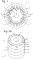
- Figure 1 shows a cross-section of an electric motor 1, especially an electric motor for driving a vehicle such as a car, the electric motor having a rotor 10 and a stator 20.
- the stator has electrical windings 21 for an electrical current inducing a magnetic field interacting with a magnetic field of permanent magnets 13 of the rotor 10 so as to drive the rotor core 10 into rotation.
- electric motors may have a large variety of configurations for the electrical windings and magnets.
- An axle or shaft 16 mounted in a central opening or central through-hole 15 of the rotor 10 along axis A is driven into rotation by driving the rotor 10 into rotation.
- the shaft 16 is the driving shaft of the electric motor 1 for transferring rotation of the electric motor to a driven assembly.
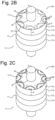
- Figure 2B shows an embodiment of a rotor core 10A comprising a rotor core body 11 having magnet cavities 12 distributed around the longitudinal axis A of the rotor core and rotor core body.
- the magnet cavities 12 extend along the longitudinal axis A between opposing first and second rotor core ends 11.1, 11.2 of the rotor core body.
- the rotor core body has a height as measured between the first and second rotor core ends, and a central opening 15 with the axle 16 received therein.
- the magnet cavities 12 each have an opening 12.1 at one or both of the first and second rotor core ends.
- the rotor body 11, in the embodiment shown, is made up of four rotor core body segments 11A that each have magnet cavity segments 12A of height h.
- the magnet cavity segments of adjacent rotor core body segments are slightly offset with respect to one another but in contact to allow passing fluid molding material between adjacent magnet cavity segments.
- the magnet cavity segments 12A in contact with one another form a magnet cavity 12.
- Permanent magnets 13 are inserted into the magnet cavity segments 12A of the magnet cavities 12, after which rotor core segments 11A are stacked, as is shown in figure 2A .
- the axle 16 is provided into central through-hole 15 of the rotor core body to project from the central through-hole of the rotor core body with respect to the rotor core body ends 11.1, 11.2 to arrive at the unmolded rotor core of figure 2B .
- Figure 2B shows the unmolded rotor core 10A
- figure 2C shows the molded rotor core 10B
- Figure 2A shows the unmolded rotor core prior to inserting the shaft 16 into the central through hole 15.
- the molded rotor core 10B basically is the rotor provided inside the stator when assembling an electric motor.
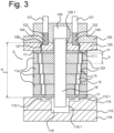
- Rotor core end caps may, for instance, be provided on the rotor core body ends 11.1, 11.2 as part of the rotor core.
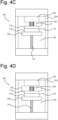
- the first (bottom) mold 110 with the unmolded rotor core and runner plate 125 placed thereon, in use, is moved upwards and pressed against the second (top) mold 120.
- Figure 3 shows the rotor core body with the rotor core end caps clamped and pressed between the first mold 110 and the second mold 120.
- the runner gate plate 125 becomes part of the second mold 120 when the rotor core is clamped and pressed between the first and second molds 110, 120 along a clamping direction that is parallel to a longitudinal direction of the shaft or axle 16.
- the top part 115 of the first mold is, as said, specifically configured to the rotor core to be processed.
- the top part 115 has venting channels 115.1 of which top side openings are associated and aligned with the magnet cavities 12 of the rotor core processed in the molding system, and allow air to escape from the magnet cavities while fluid molding material is introduced at the top sides of the magnet cavities.
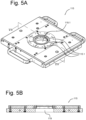
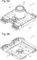
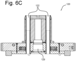
- Figure 6A and 6B show top and bottom perspective views of an embodiment of the second mold 120, and figure 6C shows a cross-section.
- a plurality of cylinder reservoirs 122 is provided around a recess 129 for receiving the shaft 16 projecting upwards from the rotor core body process in the molding system.
- the respective plungers associated with the cylinder reservoirs are not shown in figure 6A . They will enter into the cylinder reservoirs 122 from above. Open bottom ends of the cylinder reservoirs are visible in figure 6B .
- the second mold 120 has heating elements for heating the rotor core from above and for heating the molding material in the cylinder reservoirs during the molding process.
- Fluid molding material will leave the cylinder reservoirs from the open bottom ends when pressed out of the cylinder reservoirs by the respective plungers and enter into channels 126 and subsequently in the gates 127 of the runner gate plate 125 as part of the second mold during the molding process.
- the central opening 129.1 in the runner gate plate 125 as part of the second mold 120 during the molding process is part of the recess 129 in the second mold 120. In some embodiments the opening 129.1 in the runner gate plate could even fully provide the recess 129 in the second mold.
Landscapes
- Engineering & Computer Science (AREA)
- Power Engineering (AREA)
- Manufacturing & Machinery (AREA)
- Mechanical Engineering (AREA)
- Permanent Field Magnets Of Synchronous Machinery (AREA)
- Manufacture Of Motors, Generators (AREA)
Claims (8)
- Herstellungsverfahren für einen Rotorkern zum Formen von Permanentmagneten in einem ungeformten Rotorkern, um einen geformten Rotorkern für einen Elektromotor bereitzustellen,wobei ein ungeformter Rotorkern (10A) eine Welle (16) des Elektromotors (1) und einen Rotorkernkörper (11) umfasst, der ein zentrales Durchgangsloch (15) aufweist, das sich entlang und um eine Längsachse (A) des Rotorkernkörpers erstreckt, wobei Magnethohlräume (12) um die Längsachse (A) verteilt sind und Permanentmagnete (13) in die Magnethohlräume eingesetzt sind, die Welle des Elektromotors in dem zentralen Durchgangsloch angeordnet ist, die Magnethohlräume und das zentrale Durchgangsloch sich entlang der Längsachse zwischen gegenüberliegenden ersten und zweiten Rotorkernkörperenden (11.1, 11.2) des Rotorkernkörpers erstrecken und die Magnethohlräume eine Öffnung (12.1) an einem oder beiden der ersten und zweiten Rotorkernkörperenden zum Füllen der Magnethohlräume mit einem fluiden Formungsmaterial aufweisen, wobei die Welle aus dem zentralen Durchgangsloch des Rotorkernkörpers in Bezug auf eines oder beide Enden des Rotorkernkörpers vorsteht,wobei ein geformter Rotorkern (10B) den Rotorkernkörper (11) umfasst, der die Permanentmagnete aufweist, die in den Magnethohlräumen durch ein ausgehärtetes Formungsmaterial (14) in den Magnethohlräumen fixiert sind, undwobei das Verfahren Folgendes umfasst- Bereitstellen eines ungeformten Rotorkerns;- Bereitstellen eines Druckformungssystems für den Rotorkern (100), das eine erste Form (110) und eine zweite Form (120) aufweist, die konfiguriert und angeordnet sind, um in einer offenen Konfiguration der ersten Form und der zweiten Form den ungeformten Rotorkern zwischen der ersten und der zweiten Form einzusetzen, wobei die ersten und zweiten Rotorkernkörperenden entlang einer Klemmrichtung in Richtung der entsprechenden ersten und zweiten Form gerichtet sind, und in einer geschlossenen Konfiguration der ersten Form und der zweiten Form den Rotorkernkörper des nicht ausgeformten Rotorkerns zwischen der ersten und der zweiten Form festzuklemmen, um durch die erste und die zweite Form Druck entlang der Klemmrichtung auf den festgeklemmten Rotorkernkörper auszuüben, und ein fluides Formungsmaterial in den Magnethohlräumen des nicht ausgeformten Rotorkerns bereitzustellen, der zwischen der ersten und der zweiten Form festgeklemmt ist, wobei die erste Form und die zweite Form konfiguriert sind, um darin die Welle zu empfangen, die aus dem zentralen Durchgangsloch des Rotorkernkörpers in Bezug auf die Enden des Rotorkernkörpers vorsteht, die erste Form eine Vertiefung oder eine Öffnung darin umfasst, um die Welle zu empfangen, die aus dem zentralen Durchgangsloch des Rotorkernkörpers in Bezug auf das jeweilige Rotorkernkörperende vorsteht, und die Vertiefung oder die Öffnung in der ersten Form so dimensioniert ist, dass die Welle die erste Form nicht berührt, um eine Kraft in der Klemmrichtung auszuüben, wenn der Rotorkern zwischen der ersten Form und der zweiten Form festgeklemmt wird, und die zweite Form eine Vertiefung oder eine Öffnung darin umfasst, um die Welle zu empfangen, die aus dem zentralen Durchgangsloch des Rotorkernkörpers in Bezug auf das jeweilige Rotorkernkörperende vorsteht, und die Vertiefung oder die Öffnung in der zweiten Form so dimensioniert ist, dass die Welle die zweite Form nicht berührt, um eine Kraft in der Klemmrichtung auszuüben, wenn der Rotorkern zwischen der ersten Form und der zweiten Form festgeklemmt wird;- Einsetzen des ungeformten Rotorkerns zwischen der ersten Form (110) und der zweiten Form (120) des Rotorkernformsystems (100) in der offenen Konfiguration der ersten und zweiten Form, wobei die ersten und zweiten Körperenden des Rotorkerns in Richtung der jeweiligen ersten und zweiten Form gerichtet sind;- Schließen der ersten und zweiten Form von der offenen Konfiguration zur geschlossenen Konfiguration durch Bewegen der ersten und zweiten Form aufeinander zu, um den Rotorkernkörper des nicht geformten Rotorkerns mit einem vorbestimmten Druck zwischen der ersten und zweiten Form in der geschlossenen Konfiguration festzuklemmen;- Bereitstellen eines fluiden Formungsmaterials in den Magnetkammern des ungeformten Rotorkernkörpers, der zwischen der ersten und zweiten Form eingeklemmt ist;- Aushärtenlassen des fluiden Formungsmaterials in den Magnethohlräumen, um einen geformten Rotorkern bereitzustellen;- Öffnen der ersten und zweiten Form in die offene Konfiguration, indem die erste und zweite Form voneinander weg bewegt werden; und- Entfernen des geformten Rotorkerns aus dem Zwischenraum zwischen der ersten und zweiten Form.
- Verfahren nach dem vorstehenden Anspruch, wobei eine Rotorkernendkappe (17) an einem oder beiden Enden des ersten und zweiten Rotorkernkörpers bereitgestellt wird und eine oder beide Rotorkernendkappen darin Kappenöffnungen (17.1) aufweisen, wobei die Kappenöffnungen den Magnethohlräumen im Rotorkernkörper zugeordnet sind, um fluides Formungsmaterial durch die jeweiligen Kappenöffnungen in die Magnethohlräume bereitzustellen und Luft aus den Magnethohlräumen entweichen zu lassen, während die Magnethohlräume mit fluidem Formungsmaterial gefüllt werden.
- Verfahren nach dem vorstehenden Anspruch, wobei ein fluides Formgebungsmaterial in den Magnetkammern bereitgestellt wird, sodass die Öffnungen der einen oder beider Endkappen mindestens teilweise gefüllt werden.
- Druckformsystem für einen Rotorkern zum Formen von Permanentmagneten in einem ungeformten Rotorkern, um einen geformten Rotorkern für einen Elektromotor bereitzustellen,wobei ein ungeformter Rotorkern (10A) eine Welle (16) des Elektromotors (1) und einen Rotorkernkörper (11) umfasst, der ein zentrales Durchgangsloch (15) aufweist, das sich entlang und um eine Längsachse (A) des Rotorkernkörpers erstreckt, wobei Magnethohlräume (12) um die Längsachse (A) verteilt sind und Permanentmagnete (13) in die Magnethohlräume eingesetzt sind, die Welle des Elektromotors in dem zentralen Durchgangsloch angeordnet ist, die Magnethohlräume und das zentrale Durchgangsloch sich entlang der Längsachse zwischen gegenüberliegenden ersten und zweiten Rotorkernkörperenden (11.1, 11.2) des Rotorkernkörpers erstrecken und die Magnethohlräume eine Öffnung (12.1) an einem oder beiden der ersten und zweiten Rotorkernkörperenden zum Füllen der Magnethohlräume mit einem fluiden Formungsmaterial aufweisen, wobei die Welle aus dem zentralen Durchgangsloch des Rotorkernkörpers in Bezug auf eines oder beide Enden des Rotorkernkörpers vorsteht,wobei ein geformter Rotorkern (10B) den Rotorkernkörper (11) umfasst, der die Permanentmagnete aufweist, die in den Magnethohlräumen durch ein ausgehärtetes Formungsmaterial (14) in den Magnethohlräumen fixiert sind, undwobei das System eine erste Form (110) und eine zweite Form (120) umfasst, die konfiguriert und angeordnet sind, um in einer offenen Konfiguration der ersten Form und der zweiten Form den ungeformten Rotorkern zwischen der ersten und der zweiten Form einzusetzen, wobei die ersten und zweiten Rotorkernkörperenden entlang einer Klemmrichtung in Richtung der entsprechenden ersten und zweiten Form gerichtet sind, und in einer geschlossenen Konfiguration der ersten Form und der zweiten Form den Rotorkernkörper des nicht ausgeformten Rotorkerns zwischen der ersten und der zweiten Form festzuklemmen, um durch die erste und die zweite Form Druck entlang der Klemmrichtung auf den festgeklemmten Rotorkernkörper auszuüben, und ein fluides Formungsmaterial in den Magnethohlräumen des nicht ausgeformten Rotorkerns bereitzustellen, der zwischen der ersten und der zweiten Form festgeklemmt ist, wobei die erste Form und die zweite Form konfiguriert sind, um darin die Welle zu empfangen, die aus dem zentralen Durchgangsloch des Rotorkernkörpers in Bezug auf die Enden des Rotorkernkörpers vorsteht, die erste Form eine Vertiefung oder eine Öffnung darin umfasst, um die Welle zu empfangen, die aus dem zentralen Durchgangsloch des Rotorkernkörpers in Bezug auf das jeweilige Rotorkernkörperende vorsteht, und die Vertiefung oder die Öffnung in der ersten Form so dimensioniert ist, dass die Welle die erste Form nicht berührt, um eine Kraft in der Klemmrichtung auszuüben, wenn der Rotorkern zwischen der ersten Form und der zweiten Form festgeklemmt wird, und die zweite Form eine Vertiefung oder eine Öffnung darin umfasst, um die Welle zu empfangen, die aus dem zentralen Durchgangsloch des Rotorkernkörpers in Bezug auf das jeweilige Rotorkernkörperende vorsteht, und die Vertiefung oder die Öffnung in der zweiten Form so dimensioniert ist, dass die Welle die zweite Form nicht berührt, um eine Kraft in der Klemmrichtung auszuüben, wenn der Rotorkern zwischen der ersten Form und der zweiten Form festgeklemmt wird.
- System oder Verfahren nach einem der vorstehenden Ansprüche, wobei eines oder beide der ersten und zweiten Form eine Vielzahl von Zylinderreservoirs und Kolben, die den jeweiligen Zylinderreservoirs der Vielzahl von Zylinderreservoirs zugeordnet sind, umfassen, um fluides Formungsmaterial in die Magnetkammern des Rotorkernkörpers des ungeformten Rotorkerns zu bringen, und die Zylinderreservoirs der Vielzahl von Zylinderreservoirs um die Vertiefung oder Öffnung herum angeordnet sind, um die Welle aufzunehmen, die aus dem zentralen Durchgangsloch des Rotorkernkörpers herausragt.
- Verfahren oder System nach einem der vorstehenden Ansprüche, wobei die zweite Form (120) konfiguriert ist, um fluides Formungsmaterial in den Magnetkammern des Rotorkernkörpers des ungeformten Rotorkerns bereitzustellen, und die erste Form (110) ein austauschbares Teil (115) umfasst, das mit dem zu verarbeitenden ungeformten Rotorkern (10A) in Kontakt kommt und für diesen konfiguriert ist, wobei das austauschbare Teil (115) eine Öffnung (119.1) umfasst, die mindestens einen Teil der Vertiefung (119) oder der Öffnung zum Empfangen der Welle, die aus dem zentralen Durchgangsloch des Rotorkernkörpers vorsteht, bildet.
- Verfahren oder System nach einem der vorstehenden Ansprüche, wobei die zweite Form (120) konfiguriert ist, um fluides Formungsmaterial in den Magnetkammern des Rotorkernkörpers des nicht geformten Rotorkerns bereitzustellen, und die erste Form (110) Entlüftungskanäle (115.1) umfasst, deren Öffnungen den Magnethohlräumen (12) des zu bearbeitenden Rotorkerns zugeordnet und mit diesen ausgerichtet sind, um das Entweichen von Luft aus den Magnethohlräumen zu ermöglichen, während fluides Formungsmaterial in die Magnethohlräume eingeführt wird.
- Verfahren oder System nach den vorstehenden zwei Ansprüchen, wobei die Entlüftungskanäle (115.1) und deren Öffnungen in dem austauschbaren Teil (115) bereitgestellt werden.
Applications Claiming Priority (2)
| Application Number | Priority Date | Filing Date | Title |
|---|---|---|---|
| NL2028010A NL2028010B1 (en) | 2021-04-19 | 2021-04-19 | Rotor Core Manufacturing Method, and rotor core molding system therefore |
| PCT/NL2022/050213 WO2022225392A1 (en) | 2021-04-19 | 2022-04-19 | Rotor core manufacturing method, and rotor core molding system therefore |
Publications (3)
| Publication Number | Publication Date |
|---|---|
| EP4327439A1 EP4327439A1 (de) | 2024-02-28 |
| EP4327439C0 EP4327439C0 (de) | 2025-06-04 |
| EP4327439B1 true EP4327439B1 (de) | 2025-06-04 |
Family
ID=77627439
Family Applications (1)
| Application Number | Title | Priority Date | Filing Date |
|---|---|---|---|
| EP22720790.9A Active EP4327439B1 (de) | 2021-04-19 | 2022-04-19 | Verfahren zur herstellung eines rotorkerns und rotorkernformsystem dafür |
Country Status (9)
| Country | Link |
|---|---|
| US (1) | US12184135B2 (de) |
| EP (1) | EP4327439B1 (de) |
| JP (1) | JP7600434B2 (de) |
| KR (1) | KR102795569B1 (de) |
| CN (1) | CN117321896B (de) |
| CA (1) | CA3215996A1 (de) |
| MX (1) | MX2023012428A (de) |
| NL (1) | NL2028010B1 (de) |
| WO (1) | WO2022225392A1 (de) |
Families Citing this family (2)
| Publication number | Priority date | Publication date | Assignee | Title |
|---|---|---|---|---|
| TWI811078B (zh) * | 2022-08-25 | 2023-08-01 | 晉弘科技股份有限公司 | 內視鏡的光源影像模組及其製作方法 |
| JP2024157333A (ja) * | 2023-04-25 | 2024-11-07 | トヨタ紡織株式会社 | ロータ及びロータの製造方法 |
Family Cites Families (36)
| Publication number | Priority date | Publication date | Assignee | Title |
|---|---|---|---|---|
| NL193748C (nl) * | 1991-02-26 | 2000-09-04 | Boschman Tech Bv | Spuitgietinrichting. |
| NL193526C (nl) * | 1991-02-26 | 2000-01-04 | Boschman Tech Bv | Inrichting voor het omhullen van elektronische onderdelen met een kunststof. |
| JP2000166190A (ja) * | 1998-11-30 | 2000-06-16 | Toshiba Corp | 永久磁石形モータのロータ製造装置及び永久磁石形モータの製造方法 |
| JP2002044915A (ja) * | 2000-07-27 | 2002-02-08 | Yamaha Motor Co Ltd | 磁石埋込型回転子及び充填方法 |
| NL1021266C2 (nl) * | 2002-08-13 | 2004-02-17 | Otb Group Bv | Werkwijze en inrichting voor het geheel of ten dele bedekken van ten minste één elektronische component met een compound. |
| JP2004336927A (ja) * | 2003-05-09 | 2004-11-25 | Nissan Motor Co Ltd | 電動機回転子の製造装置及び製造方法 |
| JP2006035831A (ja) | 2004-07-30 | 2006-02-09 | Uchihama Kasei Kk | モーター用ローターの製造法 |
| JP4850528B2 (ja) * | 2006-02-08 | 2012-01-11 | トヨタ自動車株式会社 | ロータの製造方法 |
| JP4948040B2 (ja) | 2006-05-30 | 2012-06-06 | 株式会社三井ハイテック | 回転子積層鉄心の樹脂封止方法 |
| NL1032888C2 (nl) * | 2006-11-17 | 2008-05-20 | Sven Erik Brouwer | Waterdicht afsluitbare houder. |
| ITMI20112149A1 (it) * | 2011-11-25 | 2013-05-26 | Sisme Spa | Metodo perfezionato per rivestire con materiale plastico un rotore di un motore elettrico a magneti permanenti usato in una pompa per elettrodomestico e rotore cosi' ottenuto |
| JP2014057433A (ja) * | 2012-09-12 | 2014-03-27 | Daikin Ind Ltd | 回転電気機械 |
| JP6135770B2 (ja) * | 2013-10-02 | 2017-05-31 | 富士電機株式会社 | 永久磁石埋め込み式回転電機およびその製造方法 |
| JP2016039676A (ja) * | 2014-08-06 | 2016-03-22 | トヨタ紡織株式会社 | 回転電機のロータコア及びその製造方法 |
| JP2016093006A (ja) * | 2014-11-06 | 2016-05-23 | 株式会社三井ハイテック | 回転子の製造方法 |
| JP2016152653A (ja) * | 2015-02-16 | 2016-08-22 | 株式会社ジェイテクト | 磁石埋込型ロータの製造装置及び磁石埋込型ロータの製造方法 |
| JP6572623B2 (ja) * | 2015-05-14 | 2019-09-11 | アイシン・エィ・ダブリュ株式会社 | 樹脂充填方法 |
| JP2017005854A (ja) * | 2015-06-10 | 2017-01-05 | 日本電産テクノモータ株式会社 | ロータ、モータ、およびロータの製造方法 |
| US10821637B2 (en) * | 2016-10-31 | 2020-11-03 | Mitsui High-Tec, Inc. | Resin injection apparatus and method of manufacturing core product |
| JP6597594B2 (ja) * | 2016-12-27 | 2019-10-30 | トヨタ自動車株式会社 | 回転子製造装置 |
| DE102017126143A1 (de) * | 2017-11-08 | 2019-05-09 | C. & E. Fein Gmbh | EC-Motor mit vergossener Ankerwelle |
| JP7113694B2 (ja) * | 2018-07-31 | 2022-08-05 | 株式会社三井ハイテック | 鉄心製品の製造方法及び鉄心製品の製造装置 |
| JP6933624B2 (ja) | 2018-10-05 | 2021-09-08 | 株式会社三井ハイテック | 回転子の製造方法 |
| WO2020075275A1 (ja) * | 2018-10-11 | 2020-04-16 | 黒田精工株式会社 | ロータコア保持治具、磁石埋込み型コアの製造装置及び製造方法 |
| WO2020095349A1 (ja) * | 2018-11-05 | 2020-05-14 | 黒田精工株式会社 | 磁石埋込み型コアの製造装置及び製造方法 |
| JP7132143B2 (ja) * | 2019-02-05 | 2022-09-06 | ファナック株式会社 | ロータコアの製造装置及びロータコアの製造方法 |
| JP2020127293A (ja) * | 2019-02-05 | 2020-08-20 | ファナック株式会社 | ロータコアの製造装置及びロータコアの製造方法、並びにロータ構造 |
| JP6898370B2 (ja) * | 2019-02-12 | 2021-07-07 | ファナック株式会社 | ロータコアの製造装置及びロータコアの製造方法 |
| JP7363296B2 (ja) * | 2019-09-30 | 2023-10-18 | ニデック株式会社 | ホルダ、ロータ、モータ、およびロータの製造方法 |
| NL2024038B1 (en) * | 2019-10-17 | 2021-06-22 | Boschman Tech B V | Component Processing Apparatus, such as a Pressure Sintering Apparatus or a Component Encapsulation Apparatus |
| US11190090B1 (en) * | 2020-05-22 | 2021-11-30 | Gallant Micro. Machining Co., Ltd. | Apparatus for automated encapsulation of motor rotor core with magnet steel |
| JP7414666B2 (ja) * | 2020-08-19 | 2024-01-16 | 株式会社三井ハイテック | コア部製造装置 |
| JP7422629B2 (ja) * | 2020-08-21 | 2024-01-26 | 株式会社三井ハイテック | 鉄心製品の製造方法、残留樹脂の除去方法及び残留樹脂の除去装置 |
| NL2027722B1 (en) * | 2021-03-08 | 2022-09-26 | Boschman Tech Bv | Rotor Core Molding Method and System for Molding a Rotor Core of an Electric Motor |
| KR102686251B1 (ko) * | 2021-09-06 | 2024-07-18 | 주식회사 비엠씨 | 로터 코어의 마그넷 몰딩 장치 |
| JP2024070957A (ja) * | 2022-11-14 | 2024-05-24 | トヨタ自動車株式会社 | ローターの製造方法、ローター、駆動装置及びエンドプレート |
-
2021
- 2021-04-19 NL NL2028010A patent/NL2028010B1/en active
-
2022
- 2022-04-19 US US18/556,191 patent/US12184135B2/en active Active
- 2022-04-19 EP EP22720790.9A patent/EP4327439B1/de active Active
- 2022-04-19 WO PCT/NL2022/050213 patent/WO2022225392A1/en not_active Ceased
- 2022-04-19 CN CN202280035694.5A patent/CN117321896B/zh active Active
- 2022-04-19 MX MX2023012428A patent/MX2023012428A/es unknown
- 2022-04-19 KR KR1020237039468A patent/KR102795569B1/ko active Active
- 2022-04-19 JP JP2023564190A patent/JP7600434B2/ja active Active
- 2022-04-19 CA CA3215996A patent/CA3215996A1/en active Pending
Also Published As
| Publication number | Publication date |
|---|---|
| MX2023012428A (es) | 2024-02-09 |
| EP4327439C0 (de) | 2025-06-04 |
| CN117321896A (zh) | 2023-12-29 |
| JP7600434B2 (ja) | 2024-12-16 |
| KR20230165861A (ko) | 2023-12-05 |
| CN117321896B (zh) | 2024-08-23 |
| NL2028010B1 (en) | 2022-10-31 |
| JP2024513531A (ja) | 2024-03-25 |
| US20240235347A1 (en) | 2024-07-11 |
| KR102795569B1 (ko) | 2025-04-15 |
| EP4327439A1 (de) | 2024-02-28 |
| WO2022225392A1 (en) | 2022-10-27 |
| US12184135B2 (en) | 2024-12-31 |
| CA3215996A1 (en) | 2022-10-27 |
Similar Documents
| Publication | Publication Date | Title |
|---|---|---|
| EP4327439B1 (de) | Verfahren zur herstellung eines rotorkerns und rotorkernformsystem dafür | |
| CN103069698B (zh) | 叠积式铁心的制造方法 | |
| US11552540B2 (en) | Method of manufacturing magnet embedded core | |
| US11201527B2 (en) | Device, method, and jig for manufacturing magnet embedded core | |
| JP7163610B2 (ja) | ロータコアの製造装置及び製造方法 | |
| US20240146160A1 (en) | Rotor core molding method and system for molding a rotor core of an electric motor | |
| JP7756016B2 (ja) | 回転電機のコア部製造方法及びコア部製造装置 | |
| EP0112941A1 (de) | Verfahren zur Herstellung eines Läufers für eine dynamo-elektrische Maschine | |
| KR102686251B1 (ko) | 로터 코어의 마그넷 몰딩 장치 | |
| US11996746B2 (en) | Method and apparatus for transfer molding of electric motor cores and magnetizable inserts | |
| KR20220160884A (ko) | 모터코어의 제조장치 | |
| KR20220160886A (ko) | 모터코어의 제조장치 | |
| KR102674855B1 (ko) | 모터코어의 제조장치 | |
| US20250364857A1 (en) | Apparatus for securing a rotor core | |
| US20230026066A1 (en) | Rotor for an electric machine having a widened filling or venting opening | |
| US20250330070A1 (en) | Rotor manufacturing apparatus | |
| KR20220160885A (ko) | 모터코어의 제조장치 | |
| KR20240057789A (ko) | 로터 제조 장치 | |
| KR20220160883A (ko) | 모터코어의 제조장치 | |
| JP2023028833A (ja) | 回転電機のコア部製造方法及びコア部製造装置 |
Legal Events
| Date | Code | Title | Description |
|---|---|---|---|
| STAA | Information on the status of an ep patent application or granted ep patent |
Free format text: STATUS: UNKNOWN |
|
| STAA | Information on the status of an ep patent application or granted ep patent |
Free format text: STATUS: THE INTERNATIONAL PUBLICATION HAS BEEN MADE |
|
| PUAI | Public reference made under article 153(3) epc to a published international application that has entered the european phase |
Free format text: ORIGINAL CODE: 0009012 |
|
| STAA | Information on the status of an ep patent application or granted ep patent |
Free format text: STATUS: REQUEST FOR EXAMINATION WAS MADE |
|
| 17P | Request for examination filed |
Effective date: 20231019 |
|
| AK | Designated contracting states |
Kind code of ref document: A1 Designated state(s): AL AT BE BG CH CY CZ DE DK EE ES FI FR GB GR HR HU IE IS IT LI LT LU LV MC MK MT NL NO PL PT RO RS SE SI SK SM TR |
|
| DAV | Request for validation of the european patent (deleted) | ||
| DAX | Request for extension of the european patent (deleted) | ||
| GRAP | Despatch of communication of intention to grant a patent |
Free format text: ORIGINAL CODE: EPIDOSNIGR1 |
|
| STAA | Information on the status of an ep patent application or granted ep patent |
Free format text: STATUS: GRANT OF PATENT IS INTENDED |
|
| INTG | Intention to grant announced |
Effective date: 20241212 |
|
| GRAS | Grant fee paid |
Free format text: ORIGINAL CODE: EPIDOSNIGR3 |
|
| GRAA | (expected) grant |
Free format text: ORIGINAL CODE: 0009210 |
|
| STAA | Information on the status of an ep patent application or granted ep patent |
Free format text: STATUS: THE PATENT HAS BEEN GRANTED |
|
| AK | Designated contracting states |
Kind code of ref document: B1 Designated state(s): AL AT BE BG CH CY CZ DE DK EE ES FI FR GB GR HR HU IE IS IT LI LT LU LV MC MK MT NL NO PL PT RO RS SE SI SK SM TR |
|
| REG | Reference to a national code |
Ref country code: GB Ref legal event code: FG4D |
|
| REG | Reference to a national code |
Ref country code: CH Ref legal event code: EP |
|
| REG | Reference to a national code |
Ref country code: DE Ref legal event code: R096 Ref document number: 602022015512 Country of ref document: DE |
|
| REG | Reference to a national code |
Ref country code: IE Ref legal event code: FG4D |
|
| U01 | Request for unitary effect filed |
Effective date: 20250703 |
|
| U07 | Unitary effect registered |
Designated state(s): AT BE BG DE DK EE FI FR IT LT LU LV MT NL PT RO SE SI Effective date: 20250710 |
|
| PG25 | Lapsed in a contracting state [announced via postgrant information from national office to epo] |
Ref country code: ES Free format text: LAPSE BECAUSE OF FAILURE TO SUBMIT A TRANSLATION OF THE DESCRIPTION OR TO PAY THE FEE WITHIN THE PRESCRIBED TIME-LIMIT Effective date: 20250604 |
|
| PG25 | Lapsed in a contracting state [announced via postgrant information from national office to epo] |
Ref country code: GR Free format text: LAPSE BECAUSE OF FAILURE TO SUBMIT A TRANSLATION OF THE DESCRIPTION OR TO PAY THE FEE WITHIN THE PRESCRIBED TIME-LIMIT Effective date: 20250905 Ref country code: NO Free format text: LAPSE BECAUSE OF FAILURE TO SUBMIT A TRANSLATION OF THE DESCRIPTION OR TO PAY THE FEE WITHIN THE PRESCRIBED TIME-LIMIT Effective date: 20250904 |
|
| PG25 | Lapsed in a contracting state [announced via postgrant information from national office to epo] |
Ref country code: PL Free format text: LAPSE BECAUSE OF FAILURE TO SUBMIT A TRANSLATION OF THE DESCRIPTION OR TO PAY THE FEE WITHIN THE PRESCRIBED TIME-LIMIT Effective date: 20250604 |
|
| PG25 | Lapsed in a contracting state [announced via postgrant information from national office to epo] |
Ref country code: HR Free format text: LAPSE BECAUSE OF FAILURE TO SUBMIT A TRANSLATION OF THE DESCRIPTION OR TO PAY THE FEE WITHIN THE PRESCRIBED TIME-LIMIT Effective date: 20250604 |
|
| PG25 | Lapsed in a contracting state [announced via postgrant information from national office to epo] |
Ref country code: RS Free format text: LAPSE BECAUSE OF FAILURE TO SUBMIT A TRANSLATION OF THE DESCRIPTION OR TO PAY THE FEE WITHIN THE PRESCRIBED TIME-LIMIT Effective date: 20250904 |
|
| PG25 | Lapsed in a contracting state [announced via postgrant information from national office to epo] |
Ref country code: IS Free format text: LAPSE BECAUSE OF FAILURE TO SUBMIT A TRANSLATION OF THE DESCRIPTION OR TO PAY THE FEE WITHIN THE PRESCRIBED TIME-LIMIT Effective date: 20251004 |
|
| PG25 | Lapsed in a contracting state [announced via postgrant information from national office to epo] |
Ref country code: SM Free format text: LAPSE BECAUSE OF FAILURE TO SUBMIT A TRANSLATION OF THE DESCRIPTION OR TO PAY THE FEE WITHIN THE PRESCRIBED TIME-LIMIT Effective date: 20250604 |
|
| PG25 | Lapsed in a contracting state [announced via postgrant information from national office to epo] |
Ref country code: CZ Free format text: LAPSE BECAUSE OF FAILURE TO SUBMIT A TRANSLATION OF THE DESCRIPTION OR TO PAY THE FEE WITHIN THE PRESCRIBED TIME-LIMIT Effective date: 20250604 |
|
| PG25 | Lapsed in a contracting state [announced via postgrant information from national office to epo] |
Ref country code: SK Free format text: LAPSE BECAUSE OF FAILURE TO SUBMIT A TRANSLATION OF THE DESCRIPTION OR TO PAY THE FEE WITHIN THE PRESCRIBED TIME-LIMIT Effective date: 20250604 |