EP4317045B1 - Kran für beengte räume und basis zur installation eines solchen krans auf entsprechenden zielflächen von gebäudestrukturen oder ähnlichen tragstrukturen - Google Patents
Kran für beengte räume und basis zur installation eines solchen krans auf entsprechenden zielflächen von gebäudestrukturen oder ähnlichen tragstrukturen Download PDFInfo
- Publication number
- EP4317045B1 EP4317045B1 EP23189705.9A EP23189705A EP4317045B1 EP 4317045 B1 EP4317045 B1 EP 4317045B1 EP 23189705 A EP23189705 A EP 23189705A EP 4317045 B1 EP4317045 B1 EP 4317045B1
- Authority
- EP
- European Patent Office
- Prior art keywords
- installation base
- crane
- engagement seat
- optionally
- engagement
- Prior art date
- Legal status (The legal status is an assumption and is not a legal conclusion. Google has not performed a legal analysis and makes no representation as to the accuracy of the status listed.)
- Active
Links
Images
Classifications
-
- B—PERFORMING OPERATIONS; TRANSPORTING
- B66—HOISTING; LIFTING; HAULING
- B66C—CRANES; LOAD-ENGAGING ELEMENTS OR DEVICES FOR CRANES, CAPSTANS, WINCHES, OR TACKLES
- B66C23/00—Cranes comprising essentially a beam, boom, or triangular structure acting as a cantilever and mounted for translatory of swinging movements in vertical or horizontal planes or a combination of such movements, e.g. jib-cranes, derricks, tower cranes
- B66C23/16—Cranes comprising essentially a beam, boom, or triangular structure acting as a cantilever and mounted for translatory of swinging movements in vertical or horizontal planes or a combination of such movements, e.g. jib-cranes, derricks, tower cranes with jibs supported by columns, e.g. towers having their lower end mounted for slewing movements
- B66C23/166—Simple cranes with jibs which may be fixed or can slew or luff
-
- B—PERFORMING OPERATIONS; TRANSPORTING
- B66—HOISTING; LIFTING; HAULING
- B66C—CRANES; LOAD-ENGAGING ELEMENTS OR DEVICES FOR CRANES, CAPSTANS, WINCHES, OR TACKLES
- B66C23/00—Cranes comprising essentially a beam, boom, or triangular structure acting as a cantilever and mounted for translatory of swinging movements in vertical or horizontal planes or a combination of such movements, e.g. jib-cranes, derricks, tower cranes
- B66C23/18—Cranes comprising essentially a beam, boom, or triangular structure acting as a cantilever and mounted for translatory of swinging movements in vertical or horizontal planes or a combination of such movements, e.g. jib-cranes, derricks, tower cranes specially adapted for use in particular purposes
- B66C23/20—Cranes comprising essentially a beam, boom, or triangular structure acting as a cantilever and mounted for translatory of swinging movements in vertical or horizontal planes or a combination of such movements, e.g. jib-cranes, derricks, tower cranes specially adapted for use in particular purposes with supporting couples provided by walls of buildings or like structures
- B66C23/202—Cranes comprising essentially a beam, boom, or triangular structure acting as a cantilever and mounted for translatory of swinging movements in vertical or horizontal planes or a combination of such movements, e.g. jib-cranes, derricks, tower cranes specially adapted for use in particular purposes with supporting couples provided by walls of buildings or like structures with supporting couples provided from below, e.g. by floors of buildings
-
- B—PERFORMING OPERATIONS; TRANSPORTING
- B66—HOISTING; LIFTING; HAULING
- B66C—CRANES; LOAD-ENGAGING ELEMENTS OR DEVICES FOR CRANES, CAPSTANS, WINCHES, OR TACKLES
- B66C23/00—Cranes comprising essentially a beam, boom, or triangular structure acting as a cantilever and mounted for translatory of swinging movements in vertical or horizontal planes or a combination of such movements, e.g. jib-cranes, derricks, tower cranes
- B66C23/18—Cranes comprising essentially a beam, boom, or triangular structure acting as a cantilever and mounted for translatory of swinging movements in vertical or horizontal planes or a combination of such movements, e.g. jib-cranes, derricks, tower cranes specially adapted for use in particular purposes
- B66C23/20—Cranes comprising essentially a beam, boom, or triangular structure acting as a cantilever and mounted for translatory of swinging movements in vertical or horizontal planes or a combination of such movements, e.g. jib-cranes, derricks, tower cranes specially adapted for use in particular purposes with supporting couples provided by walls of buildings or like structures
- B66C23/208—Cranes comprising essentially a beam, boom, or triangular structure acting as a cantilever and mounted for translatory of swinging movements in vertical or horizontal planes or a combination of such movements, e.g. jib-cranes, derricks, tower cranes specially adapted for use in particular purposes with supporting couples provided by walls of buildings or like structures with supporting couples provided from the side, e.g. by walls of buildings
Definitions
- the present invention relates to a crane, in particular for lifting, handling and lowering loads in confined spaces.
- an object of the present invention is a method of assembling and installing a crane for confined spaces on corresponding target surfaces of building structures or similar supporting structures.
- the object of the present invention is in the industrial field of equipment for lifting, handling and lowering loads in confined spaces, such as special recovery and rescue cranes that are used in confined spaces, such as tanks, silos, sewage pipes, shafts, manholes, culverts and/or the like.
- such cranes comprise a support post of elongated shape extending along a prevailing direction with a first end designed to attach the crane to a target surface of a building structure or similar support structure and a second end, facing away therefrom, designed to support a respective lifting arm, which may also be telescopic.
- the lifting arm is fixed in relation to the support frame and its inclination in relation to the latter is determined during the design phase or during assembly.
- the lifting arm can be cantilevered on one side of the support post only or on both sides of the post.
- the lift arm is almost always supported and reinforced by an oblique support rod that connects a portion of the support post away from the corresponding second end to a portion of the lift arm that may also coincide with one of its ends.
- These cranes are also equipped with corresponding lifting devices that are appropriately mounted on the support post or lifting arm.
- the lifting devices fitted to such cranes comprise normally one or more hoisting mechanisms, such as a winch or other similar pull-back mechanism, equipped with a special drum on which a lifting cable is wound, the end portion of which runs along the lifting arm around at least one idler pulley located on the end of the lifting arm and from which it hangs vertically, terminating in a corresponding engagement hook.
- Activation of the lifting device in one direction or the other causes the engagement hook to be raised or lowered and, consequently, any load associated with it.
- FR1557966 An example of such a crane is shown and described in FR1557966 in which the first end of the support post has an attachment flange fitted with an attachment plate that is clamped against the horizontal target surface of the corresponding building structure or similar supporting structure by means of a plurality of threaded fasteners suitably screwed and cooperating with corresponding locking nuts.
- Confined space cranes such as the one described in FR1557966 have objective limitations in terms of adaptability and flexibility of use with respect to the different types of target surfaces that may be encountered during installation and deployment.
- the support post is generally manufactured in such a way as to present a first end with a cylindrical shape suitable for coupling to corresponding engagement housings, also with cylindrical shapes, manufactured on different types of installation bases, some configured for installations on horizontal target surfaces and others configured for installations on vertical target surfaces.
- the installation bases configured for horizontal target surfaces are provided with a flat fixing plate from which a cylindrical body develops orthogonally, defining within it the cylindrical engagement seat designed to receive the first cylindrical end of the crane support post in coupling.
- the fixing plate can be bolted or screwed to the horizontal target surface, whereby the crane support post, the first end of which is inserted into the engagement seat of the installation base and locked therein by means of a special locking element, develops vertically from the fixing plate.
- Installation bases configured for vertical target surfaces also have a flat fixing plate to which a cylindrical body is engaged. Unlike installation bases for horizontal target surfaces, the cylindrical body is not perpendicular to the fixing plate, but develops longitudinally parallel to it to provide a vertical engagement seat parallel to the vertical target surface of the respective building structure or the similar supporting structure.
- document US2021/053801 discloses the features of the preamble of independent claims 1 and 14, and it describes a confined space crane comprising an elongated vertical post having at least one annular tube and a boom hinged to an upper portion of the post. There is also provided a base or installation plate provided with a flat support portion having a square shape from which a housing bushing vertically and centrally develops to vertically accommodate the crane post. A plurality of reinforcing flaps are arranged between the flat support portion and the housing bush.
- Document EP3730447 concerns a transportable crane comprising a post, an arm that can be attached to the upper end of the post, and a diagonal rod that connects the arm to the post.
- the base has a flat, circular support portion from which a housing bushing receives the crane post vertically and centrally.
- a plurality of reinforcing flaps are arranged between the flat support portion and the housing bushing.
- Document DE10319856 refers to a support base for a crane with a substantially box-like shape, which includes a housing for the vertical engagement of the crane mast.
- the support base can be bolted to various types of installation plates.
- the aim of the present invention is therefore to substantially solve at least one of the drawbacks and/or limitations found in known solutions.
- An object of the invention is to provide a confined space crane and a base for its installation that is easy and simple to install regardless of the intended target area.
- An object of the present invention is to make the confined space crane suitable for installation on a target surface of a building structure or similar horizontal or vertical support structure without the need for specifically dedicated installation bases.
- a further object of the present invention is to reduce the overall production and/or marketing costs of such cranes.
- a further aim of the present invention is to reduce the volumes required for the storage of cranes and their accessories in the relevant warehouses.
- a crane (1) for confined spaces comprising:
- an installation base (2) for a crane (1) for confined spaces comprising at least one fixing portion (3) arranged to be fixed on a target surface of a building structure or a similar supporting structure and at least one engagement seat (4) developing predominantly transversely, preferably perpendicularly, with respect to a lying plane of the fixing portion (3) for receiving in engagement a first end (5a) of a support post (5) of a crane (1), characterized by further comprising at least one auxiliary engagement seat (10) developed transversely, optionally perpendicularly, with respect to the engagement seat (4) and also arranged to receive in engagement the first end (5a) of the support post (5) of the crane (1), the presence of the engagement seat (4) and the auxiliary engagement seat (10) allowing, by means of the fixing portion (3), the installation of the crane (1) on different target surfaces, in particular orthogonal, even more particularly on a horizontal target surface or on a vertical target surface.
- the auxiliary engagement seat (10) of the installation base (2) predominantly runs substantially parallel to the lying plane of the fixing portion (3) of the base (2).
- the fixing portion (3) of the installation base (2) comprises at least two support plates (3a) separated from each other and each lying on the same lying plane as the fixing portion (3).
- each support plate (3a) of the fixing portion (3) is provided with at least one through opening (3b) arranged to receive in engagement at least one bolt or similar threaded fastening element to the target surface of the building structure or similar support structure.
- each support plate (3a) of the fixing portion (3) is provided with two through openings (3b) arranged on opposite sides of the respective support plate (3a), each through opening (3b) being arranged to receive in engagement at least one bolt or similar threaded element for fastening to the target surface of the respective building structure or the similar supporting structure.
- each through opening (3b) of each support plate (3a) of the fixing portion (3) has a substantially oval or elliptical shape to allow, during a crane installation operation (1) for confined spaces, the adjustment of the position of the installation base (2) along at least one direction parallel to the target surface of the respective building structure or the similar supporting structure.
- each through opening (3b) of each support plate (3a) of the fixing portion (3) develops predominantly along a direction substantially orthogonal to the prevailing direction of development of the other through opening (3b) of the same support plate (3b) to allow, during a crane installation operation (1), adjustment of the position of the installation base (2) along two directions perpendicular to each other and parallel to the target surface of the respective building structure or the similar supporting structure.
- the engagement seat (4) of the installation base is defined, at least in part, by at least one first portion (4a), optionally cylindrical, made through a respective first central plate (2a) of the base (2), optionally the first central plate (2a) of the base (2) being substantially parallel to the plane of the lying plane of the fixing portion (3) of the installation base (2).
- the engagement seat (4) of the installation base (2) is defined, at least in part, by at least a second portion (4b), optionally cylindrical, respectively made through a respective second central plate (2b) of the installation base (2), optionally parallel to the first central plate (2a) of the installation base (2), in particular both central plates (2a, 2b) of the installation base (2) being substantially parallel to the lying plane of the engagement portion (3) of the installation base (2).
- the first central plate (2a) and the second central plate (2b) of the installation base (2) are spaced along the prevailing direction of development of the engagement seat (4) transversely, substantially perpendicular to the lying plane of the fixing portion (3) whereby the first portion (4a), optionally cylindrical, and the second portion (4b), optionally cylindrical, provide respective contact rings for the first end (5a) of the support post (5) of the crane (1) spaced apart from each other.
- the first portion (4a) and the second portion (4b), which at least partially define the seat of engagement (4) of the installation base (2), are identical.
- the first portion (4a) and the second portion (4b) at least partially defining the engagement seat (4) of the installation base (2) are overlapped and aligned along a transverse direction, preferably substantially perpendicular, with respect to the plane of lay of the fixing portion (3) of the installation base (2).
- the engagement seat (4) of the installation base is defined, at least in part, by at least a third portion (4c), optionally cylindrical, respectively made through a respective third central plate (2c) of the installation base (2), optionally parallel to the first and second central plates (2a, 2b) of the installation base (2), in particular all of the central plates (2a, 2b, 2c) of the installation base (2) being substantially parallel to the lying plane of the fixing portion (3) of the installation base (2).
- the third central plate (2a) and the second central plate (2b) of the installation base (2) are spaced along the prevailing direction of development of the transverse engagement seat (4), substantially perpendicular to the lying plane of the fixing portion (3) wherein the third portion (4c) and the second portion (4b) provide respective closed-form, optionally ringshaped contact elements, spaced apart from each other, for receiving in engagement the first end (5a) of the support post (5) of the crane (1).
- the portions (4a, 4b, 4c) defining at least partially the engagement seat (4) of the installation base (2) are identical.
- the portions (4a, 4b, 4c) defining the engagement seat (4) of the installation base (2) are superimposed and aligned along a transverse direction, preferably substantially perpendicular, with respect to the plane of the engagement seat (3) of the installation base (2).
- the auxiliary engagement seat (10) is defined at least in part by a tang (10a), optionally cylindrical, which develops predominantly perpendicular to the prevailing development of the engagement seat (4) of the installation base (2), optionally substantially parallel to lying plane of the fixing portion (3).
- the auxiliary engagement seat (10) is defined at least in part by two tangs (10a), optionally cylindrical, which develop predominantly perpendicular to the prevailing development of the engagement seat (4) of the installation base (2), optionally substantially parallel to lying plane of the fixing portion (3).
- the tangs (10a) defining the auxiliary engagement seat (10) of the installation base (2) are specularly identical.
- the tangs (10a) are aligned along the prevailing direction of development.
- the engagement seat (4) of the installation base (2) passes centrally through the auxiliary engagement seat (10).
- the engagement seat (4) of the installation base divides the auxiliary engagement seat (10) into the two tangs (10a).
- the auxiliary engagement seat (10) is defined at least in part by two tangs (10a), optionally cylindrical, which develop predominantly perpendicular to the prevailing development of the engagement seat (4) of the installation base (2), optionally substantially parallel with respect to lying plane of the fixing portion (3).
- the tangs (10a) defining the auxiliary engagement seat (10) of the installation base (2) are specularly identical.
- the tangs (10a) are aligned along the prevailing direction of development.
- the engagement seat (4) of the installation base (2) passes centrally through the auxiliary engagement seat (10).
- the engagement seat (4) of the installation base (2) divides the auxiliary engagement seat (10) into the two tangs (10a).
- the tangs (10a) at least partially defining the auxiliary engagement seat (10) of the installation base (2) are tangent to at least one of the central plates (2a, 2b) of the installation base (2), preferably they are tangent to the first central plate (2a) and the second central plate (2b) of the installation base (2).
- the tangs (10a) defining the auxiliary engagement seat (10) of the installation base (2) are interposed between the first central plate (2a) and the second central plate (2b) of the installation base (2).
- the third central plate (2c) of the installation base (2) is interposed between the second central plate (2b) of the installation base (2) and the support plates (3a) of the fixing portion (3) of the latter.
- the installation base (2) comprises two walls (11) substantially orthogonal with respect to the lying plane of the fixing portion (3) and substantially parallel to each other, each wall (11) extending between the first central plate (2a) of the base (2) and the respective support plate (3a) of the fixing portion (3) to define a substantially box-like or parallelepiped volume in which the engagement seat (4) and the auxiliary engagement seat (10) are defined.
- the tangs (10a) defining the auxiliary engagement seat (10) of the installation base (2) are tangent to the walls (11) of the latter.
- At least one coupling sleeve (12), optionally of cylindrical shape is interposable between at least one of the engagement seats (4, 10) of the installation base (2) and the first end (5a) of the support post (5) of the crane (1), preferably to allow coupling of different support posts (5) having first ends (5a) of different sizes with at least one of the engagement seats (4, 10) of the installation base (2).
- the coupling sleeve (12) comprises a first portion (12a), optionally cylindrical, insertable into at least one of the engagement seats (4, 10) of the installation base (2), the first portion (12a) of the coupling sleeve (12) having at least one circular shoulder (12b) projecting transversely preferably perpendicularly, outwards from one end of the first portion (12a) itself so as to rest against a corresponding edge of the corresponding engagement seat (4, 10) of the installation base 2.
- the coupling sleeve (12) comprises a second portion (12c), optionally cylindrical, which can be fitted on the first end (5a) of the support post (5) of the crane (1) and can be inserted into the first portion (12a) to ensure proper coupling between the crane (1) and the installation base (2), the first and second portions (12a, 12c), of the coupling sleeve (12) allowing the coupling of different support posts (5), having first ends (5a) of different sizes, with at least one of the engagement seats (4, 10) of the installation base (2).
- the first end (5a) of the support post (5) is arranged to engage at least one of the engagement seats (4, 10) or the respective coupling sleeve (12) associated with it by interference.
- the first portion (4a) of the engagement seat (4) of the installation base (2) has a substantially cylindrical profile.
- the first portion (4a) and the second portion (4b) of the engagement seat (4) of the installation base (2) each has a substantially cylindrical profile.
- the first portion (4a), the second portion (4b) and the third portion (4c) of the engagement seat (4) of the installation base (2) each has a substantially cylindrical profile.
- the tang (10a) of the auxiliary engagement seat (10) of the installation base (2) has a substantially cylindrical profile.
- each tang (10a) of the auxiliary engagement seat (10) of the installation base (2) has a substantially cylindrical profile.
- the coupling sleeve (12) has a substantially cylindrical profile.
- the first portion (12a) of the coupling sleeve (12) has a substantially cylindrical profile.
- the shoulder (12b) of the first portion (12a) of the coupling sleeve (12) is substantially circular.
- the second portion (12c) of the coupling sleeve (12) has a substantially cylindrical profile.
- the first end (5a) of the support post (5) of the crane (1) has a substantially cylindrical profile.
- the first portion (4a) of the engagement seat (4) of the installation base (2) does not have a cylindrical profile, optionally the profile of the first portion (4a) of the engagement seat (4) of the installation base (2) is polygonal.
- the first portion (4a) and the second portion (4b) of the installation base (2) each does not have a cylindrical profile, optionally the profile of each of the first portion (4a) and the second portion (4b) of the engagement seat (4) of the installation base (2) is polygonal.
- the first portion (4a), the second portion (4b) and the third portion (4c) of the engagement seat (4) of the installation base (2) each does not have a cylindrical profile, optionally the profile of each of the first portion (4a), the second portion (4b) and the third portion (4c) of the engagement seat (4) of the installation base (2) is polygonal.
- the tang (10a) of the auxiliary engagement seat (10) of the installation base (2) does not have a cylindrical profile, optionally the profile of the tang (10a) of the auxiliary engagement seat (10) of the installation base (2) is polygonal.
- each tang (10a) of the auxiliary engagement seat (10) of the installation base (2) does not have a cylindrical profile, optionally the profile of each tang (10a) of the auxiliary engagement seat (10) is polygonal.
- the coupling sleeve (12) does not have a cylindrical profile, optionally the profile of the coupling sleeve (12) is polygonal.
- the first portion (12a) of the coupling sleeve (12) does not have a cylindrical profile, optionally the profile of the first portion (12a) of the coupling sleeve (12) is polygonal.
- the shoulder (12b) of the first portion (12a) of the coupling sleeve (12) is not circular, optionally the profile of the shoulder (12b) of the first portion (12a) of the coupling sleeve (12) has a polygonal profile, preferably the same profile as the first portion (12a) of the coupling sleeve (12).
- the second portion (12c) of the coupling sleeve (12) does not have a cylindrical profile, optionally the profile of the second portion (12c) of the coupling sleeve (12) is polygonal.
- the first end (5a) of the support post (5) of the crane (1) does not have a cylindrical shape profile, optionally the profile of the first end (5a) of the support post (5) of the crane (1) is polygonal.
- the profile of the first end (5a) of the support post (5) of the crane (1) recalls the polygonal shape of the polygonal profile of the portions (4a, 4b, 4c) of the engagement seat (4) of the installation base (2) and/or of the tangs (10a) of the auxiliary engagement seat (10) of the installation base (2).
- the profile of the first end (5a) of the support post (5) of the crane (1) is at least partially counter shaped to the polygonal shape of the portions (4a, 4b, 4c) of the engagement seat (4) of the installation base (2) and/or of the tangs (1 0a) of the auxiliary engagement seat (10) of the installation base (2).
- the support post and/or the lifting arm (6) of the crane (1) has/present a profile, in cross-section, substantially octagonal.
- the lifting arm (6) of the crane (1) can be extended and shortened.
- the lifting arm (6) of the crane (1) is telescopic.
- the step of engaging the first end (5a) of the support post (5) of the crane (1) in one of the engagement seats (4, 10) of the installation base (2) of the crane (2) is performed either by inserting the first end (5a) of the support post (5) of the crane (1) into the engagement seat (4) which is substantially perpendicular to the plane of the laying plane of the fixing portion (3) of the base (2) when the target surface of the building structure or the similar supporting structure is substantially horizontal, or by inserting the first end (5a) of the crane support post (5) of the crane (1) into the auxiliary engagement seat (10) which develops substantially parallel to the lying plane of the fixing portion (3) of the base (2) when the target surface of the building structure or similar support structure is substantially vertical.
- a method for assembling and installing a crane (1) for confined spaces that includes:
- the step of engaging the first end (5a) of the support strut (5) of the crane (1) into the engagement seat (4, 10) of the installation base (2) of the crane (1) is carried out by engaging the first end (5a) of the support post (5) into the engagement seat (4) of the installation base (2) when the target surface of the building structure or the similar supporting structure is substantially horizontal.
- the step of engaging the first end (5a) of the support post (5) of the crane (1) in the engagement seat (4, 10) of the installation base (2) of the crane (1) is carried out by engaging the first end (5a) of the support post (5) in the auxiliary engagement seat (10) of the installation base (2) when the target surface of the building structure or the similar supporting structure is substantially vertical.
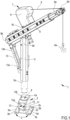
- a confined space crane according to the present invention is collectively referred to as 1.
- the crane 1 comprises a support post 5 extending along a prevailing direction having a first end 5a, optionally of cylindrical shape, arranged to engage an installation base 2 which will be described in detail below, and a second end 5b, opposite to the first end 5a, arranged to engage and support a lifting arm 6 having a cantilevered end 6a cantilevered from the support post 5.
- the lifting arm 6 on the opposite side to the cantilevered end 6a, the lifting arm 6 has a bottom end 6b which is also cantilevered from the support post 5.
- the lifting arm 6 is fixedly engaged with the second end 5b of the support frame 5 according to a predetermined orientation which is determined during the design phase or during assembly.
- the lifting arm is telescopic so that it can be lengthened or shortened.
- the crane 1 is provided with an oblique support rod 13 connecting a portion of the support post 5, intermediate to the first end 5a and the second end 5b of the latter, to the bottom end 6b of the lifting arm 6.
- the oblique support rod 13 has a first end 13a bolted to the support post 5 and a second end 13b bolted to the bottom end 6b of the lifting arm 6.
- the crane 1 can also provide for the use of at least one lifting device 7 (suitably schematized) which is removable from the support post 5 or the lifting arm 6.
- at least one lifting device 7 (suitably schematized) which is removable from the support post 5 or the lifting arm 6.
- the lifting device 7 can be mounted on the lifting arm 6 by means of a corresponding attachment portion 6c which is arranged between the cantilevered end 6a and the bottom end 6b.
- the lifting arm 6 can be provided with two or more attachment portions 6c which allow the lifting device 7 to be mounted, according to different positions, along the lifting arm 6, or different lifting devices 7 to be mounted on the same lifting arm 6.
- the lifting device 7 is provided with at least one cable 8 having a hook 8a for hooking a load to be raised or lowered.
- the cable 8 is at least partially wound on a corresponding winding mechanism 9 of the lifting device 7, operable for lifting or lowering the hook 8a and, consequently, any load associated therewith.
- the cantilevered end 6a of the latter is provided with one or more idler pulleys 6d on which the cable 8 changes its orientation to hang vertically from the cantilevered end 6a.
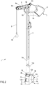
- the lifting arm 6 has a bottom end 6b solidly connected to the second end 5b of the support post 5 to form a fixed inverted 'L' structure with the latter.
- the lifting arm is not telescopic and maintains a fixed length so it cannot be extended or shortened.
- crane 1 has no oblique support rods or similar structural support elements between support arm 5 and lifting arm 6.
- the attachment portion 6c of the lifting device 7 is positioned on the support post 5, in proximity to the second end 5b of the latter, and an auxiliary idler pulley 6e is located at the connection area between the lifting arm 6 and the support post 5.
- the cable 8 then runs from the winding mechanism 9 of the lifting device 7 via the auxiliary deflection sheave 6e located at the bottom end 6b of the lifting arm 6 and the idler pulley 6d of the cantilevered end 6a of the latter, from which it hangs vertically terminating with the corresponding hook 8a.
- An additional attachment portion 6c is provided along support post 5 at a position further away from the second end 5b.
- attachment 6c allow for different engagement positions of lifting device 7 to support post 5, or the simultaneous engagement of different lifting devices 7 or otherwise to support post 5.
- Both construction solutions have, in cross-section, an external profile, of the support post 5 and/or lifting arm 6, which is substantially polygonal, preferably octagonal.
- the first end 5a of the support post 5 of the crane 1 is substantially cylindrical in shape.
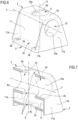
- crane 1 is advantageously equipped with an installation base 2 which allows it to be installed on a target surface of a respective building structure or similar substantially horizontal (as illustrated in Figure 1 ) or substantially vertical (as illustrated in Figure 2 ) support structure.
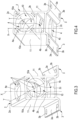
- the installation base 2 has a single body, preferably made of a single material.
- the installation base 2 comprises at least one fixing portion 3 prepared to be fixed on a target surface of a building structure or a similar supporting structure.
- the fixing portion 3 of the installation base 2 comprises at least two support plates 3a separated from each other and each lying on the same lying plane as the fixing portion 3.
- Each support plate 3a of the fixing portion 3 has a substantially rectangular shape and develops with its long sides substantially parallel to the long sides of the other support plate 3a.
- Each support plate 3a of the fixing portion 3 has two through openings 3b arranged on opposite sides of it.
- each support plate 3a of the fixing portion 3 each has a substantially oval or elliptical shape to permit adjustment of the installation position of the installation base 2 along at least one direction parallel to the target surface of the respective building structure or the similar supporting structure.
- a through opening 3b of the support plate 3a of the fixing portion 3 develops predominantly along a direction substantially orthogonal to the prevailing development of the other through opening 3b of the same support plate 3a, in order to allow an adjustment of the installation position of the installation base 2 along two directions orthogonal to each other and substantially parallel to the target surface of the respective building structure or the respective supporting structure.
- the installation base 2 comprises at least one engagement seat 4 arranged to receive in engagement, preferably by insertion, the first end 5a of the support post 5 of the crane 1.
- the engagement seat 4 of the installation base 2 runs predominantly transverse, preferably perpendicular, to a lying plane of the fixing portion 3, so that when it is engaged by the support post 5, the latter is perpendicular to the lying plane of the fixing portion 3 of the installation base 2.
- the engagement seat 4 of the installation base 2 is defined at least in part by three cylindrical portions 4a, 4b, 4c, each made through a respective central plate 2a, 2b, 2c, of the installation base 2, preferably substantially parallel to each other and substantially parallel to the lying plane of the fixing portion 3.
- the central plates 2a, 2b, 2c, of the installation base 2 are spaced apart from each other along the prevailing development axis X in such a way that the cylindrical portions 4a, 4b, 4c provide the first end 5a of the support post 5 of the crane 1 with corresponding spaced contact rings intended to engage different zones of the first end 5a of the support post itself.
- cylindrical portions 4a, 4b, 4c, which at least partially define the engagement seat 4 of the installation base 2, are identical.
- cylindrical portions 4a, 4b, 4c which at least partially define the engagement seat 4 of the installation base 2, are superimposed and aligned along the longitudinal axis of prevailing development X, namely along a transverse direction substantially perpendicular to the plane of engagement of the fixing portion 3.
- the engagement seat 4 is defined by two cylindrical portions 4a, 4b each made by means of a respective central plate 2a, 2b of the installation base 2, parallel to each other and substantially parallel to the plane of the lying plane of the fixing portion 3.
- the cylindrical portions 4a, 4b are identical and preferably overlapping and aligned along the longitudinal axis of prevailing development X.
- the engagement seat 4 of the installation base 2 is defined by a single cylindrical portion 4a, 4b, 4c which develops along the longitudinal axis of prevailing development X.
- the cylindrical portion 4a, 4b, 4c must have dimensions such as to ensure the stability of the coupling with the first portion 5a of the support post 5.
- the installation base 2 further comprises at least one auxiliary engagement seat 10 arranged to receive in engagement the first end 5a of the support post 5.
- the auxiliary engagement seat 10 develops transversely, optionally perpendicularly, with respect to the engagement seat 4, so that when it is engaged by the support post 5 the latter is substantially parallel to the lying plane of the fixing portion 3 of the installation base 2.
- the first end 5a of the support post 5 of crane 1 can be coupled to either the engagement seat 4 or the auxiliary engagement seat 10 depending on the orientation of the target surface of the respective building structure or the similar supporting structure.
- the auxiliary engagement seat 10 is defined at least in part by two cylindrical tangs 10a which develop predominantly perpendicular to the prevailing development of the engagement seat 4 of the installation base 2, optionally substantially parallel with respect to lying plane of the fixing portion 3.
- the cylindrical tangs 10a defining the auxiliary engagement seat 10 of installation base 2 are specularly identical and are aligned along the longitudinal axis of prevailing development Y.
- the auxiliary engagement seat 10 can be defined by a single cylindrical tang whose dimensions are such as to ensure the stability of the engagement of the first portion 5a of the support post 5.
- the engagement seat 4 of the installation base 2 passes centrally, substantially perpendicularly, through auxiliary engagement seat 10.
- the engagement seat 4 of the installation base 2 divides the auxiliary engagement seat 10 into the two cylindrical tangs 10a mentioned above that define it.
- the cylindrical tangs 10a which at least partially define the auxiliary engagement seat 10 of the installation base 2 are tangential to the first central plate 2a and the second central plate 2b of the installation base 2.
- the third central plate 2c of the installation base 2 is interposed between the second central plate 2b of the installation base 2 and the support plates 3a of the fixing portion 3 of the latter.
- the installation base 2 comprises two walls 11 substantially orthogonal to the lying plane of the fixing portion 3 and substantially parallel to each other.
- Each wall 11 develops between the first central plate 2a of the installation base 2 and the respective support plate 3a of the fixing portion 3 to define a substantially box-like or parallelepiped volume in which the engagement seat 4 and the auxiliary engagement seat 10 are defined.
- the cylindrical tangs 10a defining the auxiliary engagement seat 10 of the installation base 2 are tangent to the walls 11 of the latter, so that each cylindrical tang is inscribed in a substantially parallelepiped or cubic solid, however substantially box-shaped.
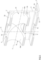
- the embodiment shown in Figures 6 and 7 provides for two auxiliary walls 11a, which are substantially orthogonal to the walls 11 and the auxiliary engagement seat 10, to close, at least in part, the installation base 2 at the front and rear, leaving the auxiliary engagement seat 10 free to accommodate the support post 5 in engagement.
- each auxiliary wall 11a has a substantially trapezoidal shape with a major base developing from one end to the other of the support plates 3a of the fixing portion 3 and a minor base coinciding, approximately, with the first central plate 2a of the installation base 2.
- the installation base 2 has a corresponding lateral concavity 14 at each support plate 3a of the fixing portion 3.
- Each lateral concavity 14 is, at least in part, delimited by a respective fixing plate 3a of the fixing portion 3, a respective wall 11 of the installation base 2 and two triangular portions 11b, opposite and facing each other, each afferent to a respective auxiliary wall 11a of the installation base 2.
- the installation base 2 it is possible to provide for the installation base 2 to be carried out by welding together different tile components, such as the embodiment shown in Figures 3 to 5 .
- the installation base 2 it is possible to provide for the installation base 2 to be made by casting and/or moulding, such as the embodiment shown in Figures 6 and 7 .
- crane 1 may be provided with at least one coupling sleeve 12 ( Figures 1 and 2 ), preferably of cylindrical shape.
- the coupling sleeve 12 comprises a first cylindrical portion 12a insertable in at least one of the engagement seats 4, 10 of the installation base 2 and has at least one circular shoulder 12b which protrudes transversely, preferably perpendicularly, outwards from one end of the first cylindrical portion 12a itself so as to rest supported against a corresponding edge of the corresponding engagement seat 4, 10 of the installation base 2.
- the coupling sleeve 12 comprises a second cylindrical portion 12c that can be fitted to the first end 5a of the support post 5 of crane 1 and inserted into the first cylindrical portion 12a to ensure correct coupling between crane 1 and installation base 2.
- the coupling sleeve 12 allows coupling between support posts 5 of crane 1 having first ends 5a of different dimensions than the dimensions of the corresponding engagement housings 4, 10 of installation base 2.
- the coupling sleeve 12 acts as an intermediate adapter between the engagement seats 4, 10 of the installation base 2 and the first end 5a of the support post 5 of the crane 1.
- Different sized coupling sleeves 12 allow the engagement seats 4, 10 of the installation base 2 to accommodate in engagement first ends 5a of different sizes of corresponding support posts 5 of different sizes.
- shapes other than cylindrical can be considered both with regard to the external shape of the first ends 5a of the support posts 5 of the cranes 1 and with regard to the inner profile of the engagement seats 4, 10 of the installation base 2.
- the external shape of the first end 5a which differs from the cylindrical shape will have to be reproduced in negative by the shape of the engagement seats 4, 10 of the installation base 2.
- the first end 5a of the support post 5 is externally counter shaped to, or closely resembles the shape of, the inner profile of the engagement seats 4, 10 of the installation base 2. Accordingly, the inner profile of each engagement seat 4, 10 of the installation base 2 is counter shaped to, or closely resembles the external shape of, the first end 5a of the support post 5.
- a first end 5a of the support post 5 of crane 1 having an elliptical or polygonal profile and engagement seats 4, 10 of the installation base 2, also having an elliptical or polygonal internal profile that recalls in negative the profile of the first end 5a of the support post 5.
- the coupling sleeve 12 must also have the same profile as the engagement housings 4, 10 of the installation base 2 and the first ends 5a of the support posts 5 of the cranes 1 in order to allow the coupling between these elements.
- a method of assembling and installing the confined space crane 1 described above is also an object of the present invention.
- the assembly and installation method includes the steps of:
- the engagement of the first end 5a of the support post 5 of the crane 1 in the engagement seat 4, 10 of the installation base 2 of the crane 1 is carried out by engaging the first end 5a of the support post 5 in the engagement seat 4 of the installation base 2 when the target surface of the building structure or the similar supporting structure is substantially horizontal.
- the engagement of the first end 5a of the support post 5 of the crane 1 into the engagement seat 4, 10 of the installation base 2 of the crane 1 is carried out by engaging the first end 5a of the support post 5 into the auxiliary engagement seat 10 of the installation base 2.
- the insertion of the first end 5 of the support post 5 into the respective engagement seat 4, 10 is carried out after the interposition of a respective coupling sleeve 12, as described above and illustrated in Figures 1 and 2 .
- the installation base 2 provided with an engagement seat 4 orthogonal to the locating plane of the fixing portion 3 and an auxiliary engagement seat 10 orthogonal to the engagement seat 4 and parallel to the locating plane of the fixing portion 3 gives the crane the flexibility to be installed on both a horizontal and a vertical target surface.
Landscapes
- Engineering & Computer Science (AREA)
- Structural Engineering (AREA)
- Mechanical Engineering (AREA)
- Civil Engineering (AREA)
- Jib Cranes (AREA)
Claims (15)
- Kran (1) für beengte Räume, umfassend:eine Installationsbasis (2), welche wenigstens einen Befestigungsabschnitt (3), welcher dazu eingerichtet ist, an einer Zielfläche einer Gebäudestruktur oder einer ähnlichen Tragestruktur befestigt zu sein, und wenigstens einen Eingriffssitz (4) aufweist, welcher vorwiegend transversal, vorzugsweise senkrecht, zu einer Ebene des Befestigungsabschnitts (3) verläuft;einen Tragepfosten (5), welcher entlang einer vorherrschenden Richtung verläuft und ein erstes Ende (5a), welches dazu eingerichtet ist, mit dem wenigstens einen Eingriffssitz (4) der Installationsbasis (2) einzugreifen, und ein zweites Ende (5b) aufweist, welches von dem ersten Ende (5a) weg weist;einen Hebearm (6), welcher mit dem Tragepfosten (5) in Eingriff steht, vorzugsweise an dem zweiten Ende (5b) des Tragepfostens (5), und wenigstens ein auskragendes Ende (6a) aufweist;optional wenigstens eine Hebevorrichtung (7), welche lösbar an dem Tragepfosten (5) oder Hebearm (6) angebracht ist, ausgerüstet mit wenigstens einem Kabel (8), welches einen Haken (8a) zum Einhaken einer anzuhebenden oder abzusenkenden Last aufweist, wobei die Hebevorrichtung (7) wenigstens einen Windenmechanismus (9) umfasst, welcher dazu betreibbar ist, den Haken (8a) und folglich die ihm zugeordnete Last anzuheben oder abzusenken;dadurch gekennzeichnet, dass die Installationsbasis (2) zusätzlich wenigstens einen Hilfs-Eingriffssitz (10) umfasst, welcher dazu eingerichtet ist, in Eingriff den Tragepfosten (5) aufzunehmen, welcher sich transversal, optional senkrecht, bezüglich des Eingriffssitzes (4) erstreckt, wobei das erste Ende (5a) des Tragepfostens (5) des Krans (1) mit dem Eingriffssitz (4) oder dem Hilfs-Eingriffssitz (10) gekoppelt ist, abhängig von der Orientierung der Zielfläche.
- Kran (1) für beengte Räume nach dem vorhergehenden Anspruch, wobei sich der Hilfs-Eingriffssitz (10) der Installationsbasis (2) vorwiegend im Wesentlichen parallel zu der Liegeebene des Befestigungsabschnitts (3) der Basis (2) erstreckt.
- Kran (1) für beengte Räume nach Anspruch 1 oder 2, wobei der Befestigungsabschnitt (3) der Installationsbasis (2) wenigstens zwei Trageplatten (3a) umfasst, welche voneinander getrennt sind und jeweils an derselben Liegeebene wie der Befestigungsabschnitt (3) liegen, wobei optional jede Trageplatte (3a) mit einer Durchgangsöffnung (3b) bereitgestellt ist, vorzugsweise zwei Durchgangsöffnungen (3b), welche an gegenüberliegenden Seiten der entsprechenden Trageplatte (3a) angeordnet sind, welche dazu eingerichtet ist, in Eingriff wenigstens einen Bolzen oder ein ähnliches mit einem Gewinde versehenes Element zum Befestigen an der Zielfläche der Gebäudestruktur oder ähnlichen Tragestruktur aufzunehmen.
- Kran (1) für beengte Räume nach einem vorhergehenden Anspruch, wobei jede Durchgangsöffnung (3b) von jeder Trageplatte (3a) des Befestigungsabschnitts (3) eine im Wesentlichen ovale oder elliptische Form aufweist, um während eines Installationsvorgangs des Krans (1) eine Anpassung der Position der Installationsbasis (2) entlang wenigstens einer Richtung parallel zu der Zielfläche der entsprechenden Gebäudestruktur oder ähnlichen Tragestruktur zu erlauben, wobei sich optional jede Durchgangsöffnung (3b) von jeder Trageplatte (3a) des Befestigungsabschnitts (3) vorwiegend entlang einer Richtung im Wesentlichen orthogonal zu der vorherrschenden Erstreckungsrichtung der anderen Durchgangsöffnung (3b) derselben Trageplatte (3b) erstreckt, um während eines Kran-Installationsvorgangs (1) eine Anpassung der Position der Installationsbasis (2) entlang zweier Richtungen senkrecht zueinander und parallel zu der Zielfläche der entsprechenden Gebäudestruktur oder ähnlichen Tragestruktur zu erlauben.
- Kran (1) für beengte Räume nach einem der vorhergehenden Ansprüche, wobei der Eingriffsort (4) der Installationsbasis (2) wenigstens teilweise definiert ist durch:wenigstens einen ersten Abschnitt (4a), optional zylindrisch, welcher durch eine entsprechende erste zentrale Platte (2a) der Basis (2) hergestellt ist, wobei optional die erste zentrale Platte (2a) der Basis (2) im Wesentlichen parallel zu der Liegeebene des Befestigungsabschnitts (3) der Installationsbasis (2) ist;durch wenigstens einen zweiten Abschnitt (4b), optional zylindrisch, welcher entsprechend durch eine entsprechende zweite zentrale Platte (2b) der Installationsbasis (2) hergestellt ist, optional parallel zu der ersten zentralen Platte (2a) der Installationsbasis (2), wobei insbesondere beide zentrale Platten (2a, 2b) der Installationsbasis (2) im Wesentlichen parallel zu der Ebene des Eingriffsabschnitts (3) der Installationsbasis (2) sind.
- Kräne (1) für beengte Räume nach einem vorhergehenden Anspruch, wobei der Eingriffssitz (4) der Installationsbasis wenigstens teilweise durch wenigstens einen dritten Abschnitt (4c) definiert ist, optional zylindrisch, welcher entsprechend durch eine entsprechende dritte zentrale Platte (2c) der Installationsbasis (2) hergestellt ist, optional parallel zu den ersten und zweiten zentralen Platten (2a, 2b) der Installationsbasis (2), wobei insbesondere alle der zentralen Platten (2a, 2b, 2c) der Installationsbasis (2) im Wesentlichen parallel zu der Liegeebene des Befestigungsabschnitts (3) der Installationsbasis (2) sind.
- Kran (1) für beengte Räume nach einem vorhergehenden Anspruch, wobei die Abschnitte (4a, 4b, 4c), optional zylindrisch, welche wenigstens teilweise den Eingriffssitz (4) der Installationsbasis (2) definieren, im Wesentlichen identisch sind, wobei optional die Abschnitte (4a, 4b, 4c), welche wenigstens teilweise den Eingriffssitz (4) der Installationsbasis (2) definieren, überlappend und entlang einer transversalen Richtung ausgerichtet sind, vorzugsweise im Wesentlichen senkrecht bezüglich der Liegeebene des Befestigungsabschnitts (3) der Installationsbasis (2).
- Kräne (1) für beengte Räume nach einem der vorhergehenden Ansprüche, wobei der Hilfs-Eingriffssitz (10) wenigstens teilweise durch zwei Zapfen (10a), optional zylindrisch, definiert ist, welche sich vorwiegend senkrecht zu der vorherrschenden Erstreckung des Eingriffssitzes (4) der Installationsbasis (2) erstrecken, optional im Wesentlichen parallel bezüglich der Ebene der Liegeebene des Befestigungsabschnitts (3).
- Kran (1) für beengte Räume nach Anspruch 8, wobei die Zapfen (10a), optional zylindrisch, welche den Hilfs-Eingriffssitz (10) der Installationsbasis (2) definieren, spiegelidentisch sind, wobei optional die Zapfen (10a) entlang der vorherrschenden Erstreckungsrichtung ausgerichtet sind.
- Kran (1) für beengte Räume nach Anspruch 8 oder 9, wobei der Eingriffssitz (4) der Installationsbasis (2) den Hilfs-Eingriffssitz (10) zentral kreuzt, wobei optional der Eingriffssitz (4) der Installationsbasis (2) den Hilfs-Eingriffssitz (10) in die beiden Zapfen (10a) unterteilt, optional zylindrisch.
- Kräne (1) für beengte Räume nach einem der drei vorhergehenden Ansprüche, wobei die Zapfen (10a), optional zylindrisch, welche wenigstens teilweise den Hilfs-Eingriffssitz (10) der Installationsbasis (2) definieren, tangential zu wenigstens einer der zentralen Platten (2a, 2b) der Installationsbasis (2) sind, wobei sie vorzugsweise tangential zu der ersten zentralen Platte (2a) und der zweiten zentralen Platte (2b) der Installationsbasis (2) sind, wobei optional die Zapfen (10a) zwischen der ersten zentralen Platte (2a) und der zweiten zentralen Platte (2b) der Installationsbasis (2) eingefügt sind, wobei weiter optional die dritte zentrale Platte (2c) der Installationsbasis (2) zwischen der zweiten zentralen Platte (2b) der Installationsbasis (2) und den Trageplatten (3a) des Befestigungsabschnitts (3) des letzteren eingefügt sind.
- Kran (1) für beengte Räume nach einem der vorhergehenden fünf Ansprüche, wobei die Installationsbasis (2) zwei Wände (11) umfasst, welche im Wesentlichen orthogonal bezüglich der Liegeebene des Befestigungsabschnitts (3) und im Wesentlichen parallel zueinander sind, wobei sich jede Wand (11) zwischen der ersten zentralen Platte (2a) der Basis (2) und der entsprechenden Trageplatte (3a) des Befestigungsabschnitts (3) erstreckt, um ein im Wesentlichen kistenartiges oder parallelepipedes Volumen zu definieren, in welchem der Eingriffssitz (4) und der Hilfs-Eingriffssitz (10) definiert sind, wobei vorzugsweise die Zapfen (10a), optional zylindrisch, welche den Hilfs-Eingriffssitz (10) der Installationsbasis (2) definieren, tangential zu den Wänden (11) davon sind.
- Kran (1) für beengte Räume nach einem der vorhergehenden Ansprüche, wobei die wenigstens eine Kopplungshülse (12), optional von zylindrischer Form, zwischen wenigstens einem der Eingriffssitze (4, 10) der Installationsbasis (2) und dem ersten Ende (5a) des Tragepfostens (5) des Krans (1) einfügbar ist, wobei optional die Kopplungshülse (12) umfasst:einen ersten Abschnitt (12a), optional zylindrisch, welcher in wenigstens einen der Eingriffssitze (4, 10) der Installationsbasis (2) eingesetzt werden kann, wobei der erste Abschnitt (12a) der Kopplungshülse (12) wenigstens eine Schulter (12b) aufweist, optional kreisförmig, welche transversal vorsteht, vorzugsweise senkrecht, nach außen von einem Ende des ersten Abschnitts (12a) selbst, um so gegen einen entsprechenden Rand des entsprechenden Eingriffssitzes (4, 10) der Installationsbasis (2) zu ruhen;einen zweiten Abschnitt (12c), optional zylindrisch, welcher an das erste Ende (5a) des Tragepfostens (5) des Krans (1) angepasst und in den ersten Abschnitt (12a) eingesetzt werden kann, um eine korrekte Kopplung zwischen dem Kran (1) und der Installationsbasis (2) sicherzustellen.
- Installationsbasis (2) für einen Kran (1) für beengte Räume, umfassend:wenigstens einen Befestigungsabschnitt (3), welcher dazu eingerichtet ist, an einer Zielfläche einer Gebäudestruktur oder ähnlichen Tragestruktur befestigt zu sein, und wenigstens einen Eingriffssitz (4), welcher sich vorwiegend transversal erstreckt, vorzugsweise senkrecht, bezüglich einer Liegeebene des Befestigungsabschnitts (3), um in Eingriff ein erstes Ende (5a) eines Tragepfostens (5) eines Krans (1) aufzunehmen,dadurch gekennzeichnet, dass sie ebenfalls umfasst:
wenigstens einen Hilfs-Eingriffssitz (10), welcher sich transversal, optional senkrecht, bezüglich des Eingriffssitzes (4) erstreckt und ebenfalls dazu eingerichtet ist, in Eingriff das erste Ende (5a) des Tragepfostens (5) des Krans (1) aufzunehmen, wobei es das Vorliegen des Eingriffssitzes (4) und des Hilfs-Eingriffssitzes (10) erlaubt, mittels des Befestigungsabschnitts (3) den Kran (1) an unterschiedlichen Zielflächen zu installieren, insbesondere orthogonal, weiter insbesondere an einer horizontalen Zielfläche oder an einer vertikalen Zielfläche. - Verfahren zum Montieren und Installieren eines Krans (1) für beengte Räume, umfassend:eine Installationsbasis (2), welche wenigstens einen Befestigungsabschnitt (3), welcher dazu eingerichtet ist, an einer Zielfläche einer Gebäudestruktur oder einer ähnlichen Tragestruktur befestigt zu werden, und wenigstens einen Eingriffssitz (4) aufweist, welcher sich vorwiegend transversal, vorzugsweise senkrecht, zu einer Liegeebene des Befestigungsabschnitts (3) erstreckt;einen Tragepfosten (5), welcher sich entlang einer vorherrschenden Richtung erstreckt und ein erstes Ende (5a), welches dazu eingerichtet ist, mit dem wenigstens einen Eingriffssitz (4) der Installationsbasis (2) einzugreifen, und ein zweites Ende (5b) aufweist, welches weg von dem ersten Ende (5a) weist;einen Hebearm (6), welcher mit dem Tragepfosten (5) in Eingriff steht, vorzugsweise an dem zweiten Ende (5b) des Tragepfostens (5), und wenigstens ein auskragendes Ende (6a) aufweist;optional wenigstens eine Hebevorrichtung (7), welche lösbar an dem Tragepfosten (5) oder Hebearm (6) angebracht ist, ausgerüstet mit wenigstens einem Kabel (8) mit einem Haken (8a) zum Einhaken einer anzuhebenden oder abzusenkenden Last, wobei die Hebevorrichtung (7) wenigstens einen Windenmechanismus (9) umfasst, welcher dazu betreibbar ist, den Haken (8a) und dementsprechend die ihm zugeordnete Last anzuheben oder abzusenken;wobei die Installationsbasis (2) zusätzlich wenigstens einen Hilfs-Eingriffssitz (10) umfasst, welcher dazu eingerichtet ist, in Eingriff den Tragepfosten (5) aufzunehmen, welcher sich transversal erstreckt, optional senkrecht, bezüglich des Eingriffssitzes (4), wobei das erste Ende (5a) des Tragepfostens (5) des Krans (1) mit dem Eingriffssitz (4) oder mit dem Hilfs-Eingriffssitz (10) gekoppelt wird, abhängig von der Orientierung der Zielfläche,wobei das Kran-Montage- und Installationsverfahren (1) die Schritte umfasst:Identifizieren einer Zielfläche einer Gebäudestruktur oder ähnlichen Tragestruktur, an welcher der Kran (1) zu installieren ist;Erkennen, ob die Zielfläche der Gebäudestruktur oder der ähnlichen Tragestruktur horizontal oder vertikal ist;Positionieren der Installationsbasis (2) des Krans (1) an der Zielfläche der Gebäudestruktur oder ähnlichen Tragestruktur in einer derartigen Weise, dass der Befestigungsabschnitt (3) der Installationsbasis (2) in Kontakt mit dieser Zielfläche steht und wenigstens einer der Eingriffssitze (4, 10) vertikal, insbesondere von oben, eingegriffen werden kann;Befestigen, optional mittels einer Mehrzahl von Bolzen oder ähnlichen mit einem Gewinde versehenen Elementen, des Befestigungsabschnitts (3) der Installationsbasis (2) des Krans (1) an der Zielfläche der entsprechenden Gebäudestruktur oder ähnlichen Tragestruktur;Eingreifen des ersten Endes (5a) des Tragepfostens (5) des Krans (1) in dem Eingriffssitz (4) der Installationsbasis (2) des Krans (1), wenn die Zielfläche der Gebäudestruktur oder ähnlichen Tragestruktur im Wesentlichen horizontal ist, oder Eingreifen des ersten Endes (5a) des Tragepfostens (5) des Krans (1) in dem Hilfs-Eingriffssitz (10) der Installationsbasis (2) des Krans (1), wenn die Zielfläche der Gebäudestruktur oder der ähnlichen Tragestruktur im Wesentlichen vertikal ist.
Applications Claiming Priority (1)
| Application Number | Priority Date | Filing Date | Title |
|---|---|---|---|
| IT102022000016905A IT202200016905A1 (it) | 2022-08-05 | 2022-08-05 | Gru per spazi confinati e base per l’installazione di tale gru su corrispettive superfici di destinazione di strutture edili o di simili strutture di supporto |
Publications (3)
| Publication Number | Publication Date |
|---|---|
| EP4317045A1 EP4317045A1 (de) | 2024-02-07 |
| EP4317045B1 true EP4317045B1 (de) | 2024-12-25 |
| EP4317045C0 EP4317045C0 (de) | 2024-12-25 |
Family
ID=83691558
Family Applications (1)
| Application Number | Title | Priority Date | Filing Date |
|---|---|---|---|
| EP23189705.9A Active EP4317045B1 (de) | 2022-08-05 | 2023-08-04 | Kran für beengte räume und basis zur installation eines solchen krans auf entsprechenden zielflächen von gebäudestrukturen oder ähnlichen tragstrukturen |
Country Status (2)
| Country | Link |
|---|---|
| EP (1) | EP4317045B1 (de) |
| IT (1) | IT202200016905A1 (de) |
Families Citing this family (1)
| Publication number | Priority date | Publication date | Assignee | Title |
|---|---|---|---|---|
| AU2021225128A1 (en) * | 2020-12-23 | 2022-07-07 | Sayfa R&D Pty Ltd | A davit assembly |
Family Cites Families (5)
| Publication number | Priority date | Publication date | Assignee | Title |
|---|---|---|---|---|
| FR1557966A (de) | 1968-02-09 | 1969-02-21 | ||
| US5445487A (en) | 1993-12-07 | 1995-08-29 | Koscinski, Jr.; Stanley | Boom lift apparatus mountable to different support structures |
| DE20207119U1 (de) * | 2002-05-06 | 2002-08-29 | Brockmann, Heinrich, 48249 Dülmen | Schweißnahtlose Hebevorrichtung |
| WO2019123145A1 (en) * | 2017-12-19 | 2019-06-27 | 3M Innovative Properties Company | Confined-space davit |
| IT201900005782A1 (it) * | 2019-04-15 | 2020-10-15 | Fin Group S R L | Dispositivo di sollevamento trasportabile |
-
2022
- 2022-08-05 IT IT102022000016905A patent/IT202200016905A1/it unknown
-
2023
- 2023-08-04 EP EP23189705.9A patent/EP4317045B1/de active Active
Also Published As
| Publication number | Publication date |
|---|---|
| IT202200016905A1 (it) | 2024-02-05 |
| EP4317045C0 (de) | 2024-12-25 |
| EP4317045A1 (de) | 2024-02-07 |
Similar Documents
| Publication | Publication Date | Title |
|---|---|---|
| KR101215356B1 (ko) | 파일 인양용 기구 | |
| KR20090109698A (ko) | 결속부재를 구비한 컨테이너 | |
| EP4317045B1 (de) | Kran für beengte räume und basis zur installation eines solchen krans auf entsprechenden zielflächen von gebäudestrukturen oder ähnlichen tragstrukturen | |
| JP2009091123A (ja) | 鉄塔用クレーン | |
| KR20110014341A (ko) | 안전펜스가 설치된 타워크레인 지지장치 | |
| JP2002356297A (ja) | 鉄塔建設用クレーン及び該クレーンを用いた鉄塔建設方法 | |
| KR102252089B1 (ko) | 빔 인상장치 | |
| KR100929311B1 (ko) | 대빗 장치 | |
| CN116621003A (zh) | 一种多吊梁的装配方法 | |
| JP6223874B2 (ja) | 揚重装置並びにそれを用いるポールの取付および取外方法 | |
| CN213112298U (zh) | 一种桅杆 | |
| JP3242775B2 (ja) | 竪型容器の据付方法 | |
| JPH09110379A (ja) | クレーン | |
| KR900008874B1 (ko) | 고소작업용 족장 및 그의 시설공법 | |
| JP2005090160A (ja) | 吊り足場 | |
| JP7388883B2 (ja) | クレーンの基礎構造部 | |
| JP2017197960A (ja) | 吊り天井用の吊り鉄骨フレームの施工方法 | |
| JP3280228B2 (ja) | 筒状巨大構造物の据付け方法 | |
| JP3179246B2 (ja) | 張出ユニット吊込治具 | |
| KR101071557B1 (ko) | 폴더형 조립식 비계 | |
| CN222974756U (zh) | 便携式车载吊机 | |
| CN213059892U (zh) | 桥梁装配专用吊具 | |
| JP7817134B2 (ja) | 腹起し材用吊り治具及び腹起し材の施工方法 | |
| CN221546425U (zh) | 一种免拆栈桥板的板底钢骨柱安装系统 | |
| KR102528987B1 (ko) | 메가급 항만 물류 자동화 구축을 위한 항만 기초구조물 시공 방법 |
Legal Events
| Date | Code | Title | Description |
|---|---|---|---|
| PUAI | Public reference made under article 153(3) epc to a published international application that has entered the european phase |
Free format text: ORIGINAL CODE: 0009012 |
|
| STAA | Information on the status of an ep patent application or granted ep patent |
Free format text: STATUS: THE APPLICATION HAS BEEN PUBLISHED |
|
| AK | Designated contracting states |
Kind code of ref document: A1 Designated state(s): AL AT BE BG CH CY CZ DE DK EE ES FI FR GB GR HR HU IE IS IT LI LT LU LV MC ME MK MT NL NO PL PT RO RS SE SI SK SM TR |
|
| STAA | Information on the status of an ep patent application or granted ep patent |
Free format text: STATUS: REQUEST FOR EXAMINATION WAS MADE |
|
| 17P | Request for examination filed |
Effective date: 20240320 |
|
| RBV | Designated contracting states (corrected) |
Designated state(s): AL AT BE BG CH CY CZ DE DK EE ES FI FR GB GR HR HU IE IS IT LI LT LU LV MC ME MK MT NL NO PL PT RO RS SE SI SK SM TR |
|
| GRAP | Despatch of communication of intention to grant a patent |
Free format text: ORIGINAL CODE: EPIDOSNIGR1 |
|
| STAA | Information on the status of an ep patent application or granted ep patent |
Free format text: STATUS: GRANT OF PATENT IS INTENDED |
|
| INTG | Intention to grant announced |
Effective date: 20240722 |
|
| GRAS | Grant fee paid |
Free format text: ORIGINAL CODE: EPIDOSNIGR3 |
|
| GRAA | (expected) grant |
Free format text: ORIGINAL CODE: 0009210 |
|
| STAA | Information on the status of an ep patent application or granted ep patent |
Free format text: STATUS: THE PATENT HAS BEEN GRANTED |
|
| AK | Designated contracting states |
Kind code of ref document: B1 Designated state(s): AL AT BE BG CH CY CZ DE DK EE ES FI FR GB GR HR HU IE IS IT LI LT LU LV MC ME MK MT NL NO PL PT RO RS SE SI SK SM TR |
|
| REG | Reference to a national code |
Ref country code: GB Ref legal event code: FG4D |
|
| REG | Reference to a national code |
Ref country code: CH Ref legal event code: EP |
|
| REG | Reference to a national code |
Ref country code: DE Ref legal event code: R096 Ref document number: 602023001490 Country of ref document: DE |
|
| REG | Reference to a national code |
Ref country code: IE Ref legal event code: FG4D |
|
| U01 | Request for unitary effect filed |
Effective date: 20250124 |
|
| U07 | Unitary effect registered |
Designated state(s): AT BE BG DE DK EE FI FR IT LT LU LV MT NL PT RO SE SI Effective date: 20250130 |
|
| PG25 | Lapsed in a contracting state [announced via postgrant information from national office to epo] |
Ref country code: HR Free format text: LAPSE BECAUSE OF FAILURE TO SUBMIT A TRANSLATION OF THE DESCRIPTION OR TO PAY THE FEE WITHIN THE PRESCRIBED TIME-LIMIT Effective date: 20241225 |
|
| PG25 | Lapsed in a contracting state [announced via postgrant information from national office to epo] |
Ref country code: NO Free format text: LAPSE BECAUSE OF FAILURE TO SUBMIT A TRANSLATION OF THE DESCRIPTION OR TO PAY THE FEE WITHIN THE PRESCRIBED TIME-LIMIT Effective date: 20250325 |
|
| PG25 | Lapsed in a contracting state [announced via postgrant information from national office to epo] |
Ref country code: GR Free format text: LAPSE BECAUSE OF FAILURE TO SUBMIT A TRANSLATION OF THE DESCRIPTION OR TO PAY THE FEE WITHIN THE PRESCRIBED TIME-LIMIT Effective date: 20250326 |
|
| PG25 | Lapsed in a contracting state [announced via postgrant information from national office to epo] |
Ref country code: RS Free format text: LAPSE BECAUSE OF FAILURE TO SUBMIT A TRANSLATION OF THE DESCRIPTION OR TO PAY THE FEE WITHIN THE PRESCRIBED TIME-LIMIT Effective date: 20250325 |
|
| PG25 | Lapsed in a contracting state [announced via postgrant information from national office to epo] |
Ref country code: SM Free format text: LAPSE BECAUSE OF FAILURE TO SUBMIT A TRANSLATION OF THE DESCRIPTION OR TO PAY THE FEE WITHIN THE PRESCRIBED TIME-LIMIT Effective date: 20241225 |
|
| PG25 | Lapsed in a contracting state [announced via postgrant information from national office to epo] |
Ref country code: PL Free format text: LAPSE BECAUSE OF FAILURE TO SUBMIT A TRANSLATION OF THE DESCRIPTION OR TO PAY THE FEE WITHIN THE PRESCRIBED TIME-LIMIT Effective date: 20241225 |
|
| PG25 | Lapsed in a contracting state [announced via postgrant information from national office to epo] |
Ref country code: ES Free format text: LAPSE BECAUSE OF FAILURE TO SUBMIT A TRANSLATION OF THE DESCRIPTION OR TO PAY THE FEE WITHIN THE PRESCRIBED TIME-LIMIT Effective date: 20241225 |
|
| PG25 | Lapsed in a contracting state [announced via postgrant information from national office to epo] |
Ref country code: IS Free format text: LAPSE BECAUSE OF FAILURE TO SUBMIT A TRANSLATION OF THE DESCRIPTION OR TO PAY THE FEE WITHIN THE PRESCRIBED TIME-LIMIT Effective date: 20250425 |
|
| PG25 | Lapsed in a contracting state [announced via postgrant information from national office to epo] |
Ref country code: SK Free format text: LAPSE BECAUSE OF FAILURE TO SUBMIT A TRANSLATION OF THE DESCRIPTION OR TO PAY THE FEE WITHIN THE PRESCRIBED TIME-LIMIT Effective date: 20241225 |
|
| PG25 | Lapsed in a contracting state [announced via postgrant information from national office to epo] |
Ref country code: CZ Free format text: LAPSE BECAUSE OF FAILURE TO SUBMIT A TRANSLATION OF THE DESCRIPTION OR TO PAY THE FEE WITHIN THE PRESCRIBED TIME-LIMIT Effective date: 20241225 |
|
| U20 | Renewal fee for the european patent with unitary effect paid |
Year of fee payment: 3 Effective date: 20250825 |
|
| PLBE | No opposition filed within time limit |
Free format text: ORIGINAL CODE: 0009261 |
|
| STAA | Information on the status of an ep patent application or granted ep patent |
Free format text: STATUS: NO OPPOSITION FILED WITHIN TIME LIMIT |
|
| 26N | No opposition filed |
Effective date: 20250926 |