EP4313609B1 - Anlage und verfahren zum vorbeschichten und drucken auf metallbändern - Google Patents
Anlage und verfahren zum vorbeschichten und drucken auf metallbändern Download PDFInfo
- Publication number
- EP4313609B1 EP4313609B1 EP22717009.9A EP22717009A EP4313609B1 EP 4313609 B1 EP4313609 B1 EP 4313609B1 EP 22717009 A EP22717009 A EP 22717009A EP 4313609 B1 EP4313609 B1 EP 4313609B1
- Authority
- EP
- European Patent Office
- Prior art keywords
- strip
- coat
- drying
- ink
- printing
- Prior art date
- Legal status (The legal status is an assumption and is not a legal conclusion. Google has not performed a legal analysis and makes no representation as to the accuracy of the status listed.)
- Active
Links
Images


Classifications
-
- B—PERFORMING OPERATIONS; TRANSPORTING
- B41—PRINTING; LINING MACHINES; TYPEWRITERS; STAMPS
- B41J—TYPEWRITERS; SELECTIVE PRINTING MECHANISMS, i.e. MECHANISMS PRINTING OTHERWISE THAN FROM A FORME; CORRECTION OF TYPOGRAPHICAL ERRORS
- B41J11/00—Devices or arrangements of selective printing mechanisms, e.g. ink-jet printers or thermal printers, for supporting or handling copy material in sheet or web form
- B41J11/0015—Devices or arrangements of selective printing mechanisms, e.g. ink-jet printers or thermal printers, for supporting or handling copy material in sheet or web form for treating before, during or after printing or for uniform coating or laminating the copy material before or after printing
- B41J11/002—Curing or drying the ink on the copy materials, e.g. by heating or irradiating
- B41J11/0022—Curing or drying the ink on the copy materials, e.g. by heating or irradiating using convection means, e.g. by using a fan for blowing or sucking air
-
- B—PERFORMING OPERATIONS; TRANSPORTING
- B41—PRINTING; LINING MACHINES; TYPEWRITERS; STAMPS
- B41J—TYPEWRITERS; SELECTIVE PRINTING MECHANISMS, i.e. MECHANISMS PRINTING OTHERWISE THAN FROM A FORME; CORRECTION OF TYPOGRAPHICAL ERRORS
- B41J11/00—Devices or arrangements of selective printing mechanisms, e.g. ink-jet printers or thermal printers, for supporting or handling copy material in sheet or web form
- B41J11/008—Controlling printhead for accurately positioning print image on printing material, e.g. with the intention to control the width of margins
-
- B—PERFORMING OPERATIONS; TRANSPORTING
- B41—PRINTING; LINING MACHINES; TYPEWRITERS; STAMPS
- B41J—TYPEWRITERS; SELECTIVE PRINTING MECHANISMS, i.e. MECHANISMS PRINTING OTHERWISE THAN FROM A FORME; CORRECTION OF TYPOGRAPHICAL ERRORS
- B41J11/00—Devices or arrangements of selective printing mechanisms, e.g. ink-jet printers or thermal printers, for supporting or handling copy material in sheet or web form
- B41J11/0095—Detecting means for copy material, e.g. for detecting or sensing presence of copy material or its leading or trailing end
-
- B—PERFORMING OPERATIONS; TRANSPORTING
- B41—PRINTING; LINING MACHINES; TYPEWRITERS; STAMPS
- B41J—TYPEWRITERS; SELECTIVE PRINTING MECHANISMS, i.e. MECHANISMS PRINTING OTHERWISE THAN FROM A FORME; CORRECTION OF TYPOGRAPHICAL ERRORS
- B41J15/00—Devices or arrangements of selective printing mechanisms, e.g. ink-jet printers or thermal printers, specially adapted for supporting or handling copy material in continuous form, e.g. webs
- B41J15/04—Supporting, feeding, or guiding devices; Mountings for web rolls or spindles
- B41J15/046—Supporting, feeding, or guiding devices; Mountings for web rolls or spindles for the guidance of continuous copy material, e.g. for preventing skewed conveyance of the continuous copy material
-
- B—PERFORMING OPERATIONS; TRANSPORTING
- B41—PRINTING; LINING MACHINES; TYPEWRITERS; STAMPS
- B41J—TYPEWRITERS; SELECTIVE PRINTING MECHANISMS, i.e. MECHANISMS PRINTING OTHERWISE THAN FROM A FORME; CORRECTION OF TYPOGRAPHICAL ERRORS
- B41J15/00—Devices or arrangements of selective printing mechanisms, e.g. ink-jet printers or thermal printers, specially adapted for supporting or handling copy material in continuous form, e.g. webs
- B41J15/16—Means for tensioning or winding the web
- B41J15/165—Means for tensioning or winding the web for tensioning continuous copy material by use of redirecting rollers or redirecting nonrevolving guides
-
- B—PERFORMING OPERATIONS; TRANSPORTING
- B41—PRINTING; LINING MACHINES; TYPEWRITERS; STAMPS
- B41J—TYPEWRITERS; SELECTIVE PRINTING MECHANISMS, i.e. MECHANISMS PRINTING OTHERWISE THAN FROM A FORME; CORRECTION OF TYPOGRAPHICAL ERRORS
- B41J29/00—Details of, or accessories for, typewriters or selective printing mechanisms not otherwise provided for
- B41J29/377—Cooling or ventilating arrangements
-
- B—PERFORMING OPERATIONS; TRANSPORTING
- B41—PRINTING; LINING MACHINES; TYPEWRITERS; STAMPS
- B41J—TYPEWRITERS; SELECTIVE PRINTING MECHANISMS, i.e. MECHANISMS PRINTING OTHERWISE THAN FROM A FORME; CORRECTION OF TYPOGRAPHICAL ERRORS
- B41J29/00—Details of, or accessories for, typewriters or selective printing mechanisms not otherwise provided for
- B41J29/38—Drives, motors, controls or automatic cut-off devices for the entire printing mechanism
- B41J29/393—Devices for controlling or analysing the entire machine ; Controlling or analysing mechanical parameters involving printing of test patterns
-
- B—PERFORMING OPERATIONS; TRANSPORTING
- B41—PRINTING; LINING MACHINES; TYPEWRITERS; STAMPS
- B41J—TYPEWRITERS; SELECTIVE PRINTING MECHANISMS, i.e. MECHANISMS PRINTING OTHERWISE THAN FROM A FORME; CORRECTION OF TYPOGRAPHICAL ERRORS
- B41J3/00—Typewriters or selective printing or marking mechanisms characterised by the purpose for which they are constructed
- B41J3/407—Typewriters or selective printing or marking mechanisms characterised by the purpose for which they are constructed for marking on special material
- B41J3/413—Typewriters or selective printing or marking mechanisms characterised by the purpose for which they are constructed for marking on special material for metal
-
- B—PERFORMING OPERATIONS; TRANSPORTING
- B41—PRINTING; LINING MACHINES; TYPEWRITERS; STAMPS
- B41M—PRINTING, DUPLICATING, MARKING, OR COPYING PROCESSES; COLOUR PRINTING
- B41M5/00—Duplicating or marking methods; Sheet materials for use therein
- B41M5/0011—Pre-treatment or treatment during printing of the recording material, e.g. heating, irradiating
- B41M5/0017—Application of ink-fixing material, e.g. mordant, precipitating agent, on the substrate prior to printing, e.g. by ink-jet printing, coating or spraying
-
- B—PERFORMING OPERATIONS; TRANSPORTING
- B41—PRINTING; LINING MACHINES; TYPEWRITERS; STAMPS
- B41M—PRINTING, DUPLICATING, MARKING, OR COPYING PROCESSES; COLOUR PRINTING
- B41M5/00—Duplicating or marking methods; Sheet materials for use therein
- B41M5/0041—Digital printing on surfaces other than ordinary paper
- B41M5/0047—Digital printing on surfaces other than ordinary paper by ink-jet printing
-
- B—PERFORMING OPERATIONS; TRANSPORTING
- B41—PRINTING; LINING MACHINES; TYPEWRITERS; STAMPS
- B41M—PRINTING, DUPLICATING, MARKING, OR COPYING PROCESSES; COLOUR PRINTING
- B41M5/00—Duplicating or marking methods; Sheet materials for use therein
- B41M5/0041—Digital printing on surfaces other than ordinary paper
- B41M5/0058—Digital printing on surfaces other than ordinary paper on metals and oxidised metal surfaces
-
- B—PERFORMING OPERATIONS; TRANSPORTING
- B41—PRINTING; LINING MACHINES; TYPEWRITERS; STAMPS
- B41M—PRINTING, DUPLICATING, MARKING, OR COPYING PROCESSES; COLOUR PRINTING
- B41M7/00—After-treatment of prints, e.g. heating, irradiating, setting of the ink, protection of the printed stock
- B41M7/0036—After-treatment of prints, e.g. heating, irradiating, setting of the ink, protection of the printed stock using protective coatings or layers dried without curing
-
- B—PERFORMING OPERATIONS; TRANSPORTING
- B41—PRINTING; LINING MACHINES; TYPEWRITERS; STAMPS
- B41M—PRINTING, DUPLICATING, MARKING, OR COPYING PROCESSES; COLOUR PRINTING
- B41M7/00—After-treatment of prints, e.g. heating, irradiating, setting of the ink, protection of the printed stock
- B41M7/009—After-treatment of prints, e.g. heating, irradiating, setting of the ink, protection of the printed stock using thermal means, e.g. infrared radiation, heat
-
- B—PERFORMING OPERATIONS; TRANSPORTING
- B41—PRINTING; LINING MACHINES; TYPEWRITERS; STAMPS
- B41J—TYPEWRITERS; SELECTIVE PRINTING MECHANISMS, i.e. MECHANISMS PRINTING OTHERWISE THAN FROM A FORME; CORRECTION OF TYPOGRAPHICAL ERRORS
- B41J11/00—Devices or arrangements of selective printing mechanisms, e.g. ink-jet printers or thermal printers, for supporting or handling copy material in sheet or web form
- B41J11/0015—Devices or arrangements of selective printing mechanisms, e.g. ink-jet printers or thermal printers, for supporting or handling copy material in sheet or web form for treating before, during or after printing or for uniform coating or laminating the copy material before or after printing
- B41J11/002—Curing or drying the ink on the copy materials, e.g. by heating or irradiating
Definitions
- the present invention relates to a plant and a process for pre-coating and digital inkjet printing of a metallic strip, making it suitable for ink adhesion.
- Pre-coated strips have a variety of applications and are widely used in the field of indoor and outdoor architecture, in civil and industrial construction and in the household appliance industry. There is a rising demand in this sector for strips with increasingly complex decorative designs.
- the usual technique for producing these pre-coated strips with complex designs involves the following steps, illustrated with reference to the attached Figure 1 :
- the first step sees the application of a first coat, the primer 10, followed by the drying 12 and subsequent cooling 14 of said primer;
- the second step involves the application of a second coat 16 , that is, the base coat, which constitutes the background of the design to be obtained, followed by drying 18 and subsequent cooling 20 of the coats.
- a third step there follows the application of the design or the print 22 , for example using thinned or unthinned inks with a solvent on the base coat of the previously created double coat, with the subsequent drying of the ink, and finally, in a fourth step, the application of a clear coat 24 also followed by drying 26 and subsequent cooling 28.
- the various steps listed above are reflected in a succession of devices in the pre-coating and printing plant, which precisely follow one another in this order: a first coating device, a first oven, a first cooling device, a second coating device, a second oven, a second cooling device, a printer, a third coating device, a third oven and a third cooling device.
- the flowchart of Figure 1 therefore represents, on the one hand, the succession of the processing steps and, on the other, the succession of the corresponding devices required to carry out each individual step in a plant or corresponding line for pre-coating and printing.
- Ink application or printing technologies have evolved technically and technologically over time, but the following techniques are generally used today: Application with printing rollers (rotogravure), usually consisting of two to five rollers, with a negative design imprinted on the roller; application with printing rollers by flexographic technique, usually consisting of a unit of two to five rubber-coated rollers with an embossed (positive) design on the rubber surface; and application with a four-colour digital inkjet printer. All technologies have their limits.
- the disadvantages associated with the roller application are as follows: The design is constrained by the circumferential development of the roller used. Each design involves the use of a dedicated series of rollers; therefore, the cost of investment is high and the management of a product portfolio with numerous designs to be produced is particularly complex.
- the object of the invention is to overcome the aforementioned drawbacks and to propose, in view of the limitations of the various techniques and technologies for pre-coating and printing on metallic strips, a plant and process for pre-coating and printing on metallic strips, which is less complex, requires fewer components, is cheaper, and preferably provides higher print resistance with a lower environmental footprint.
- the object is achieved by means of a plant for pre-coating and printing, by digital inkjet, of a metallic strip, as defined in appended claim 1, comprising, in the following order:
- Said plant which provides for the application of a single coat that performs the simultaneous functions of primer and base coat, eliminates the need, before printing, of two drying ovens, two cooling devices and two coating devices, thus halving the number of components in the pre-coating step.
- the invention makes it possible to create a pre-coating and printing line that requires only two ovens for heat drying or curing the coats, the first being necessary for the drying and thus polymerization of the initial coat, which acts as a primer and a base coat, and the second, placed after the printing unit and the application of the clear coat, being necessary for the drying/polymerization of the latter.
- the plant according to the invention is particularly suitable for printing on continuous strips.
- the plant advantageously also comprises means for conveying the strip through the various components of the plant itself.
- the printing unit comprises, in the following order:
- the strip tension control system is preferably an "S-like" bridle system.
- a possible "S-like” bridle system for controlling strip tension can be provided at the entrance of the clear coating device.
- the pass-line rollers limit the vertical vibrations of the strip.
- the strip to be printed is guided through said centring system and said first strip tension control system to be subsequently guided underneath said one or more print heads, here advantageously transported by means of a conveyor belt, and then guided to the outlet of the printing unit through said second strip tension control system.
- the conveyor can advantageously be provided with a pneumatic support surface adapted to sustain the corresponding section of the strip on an air cushion.
- the bridle systems virtually cancel out the tension in the longitudinal direction of the strip.
- Strip levelling systems placed before said one or more print heads are also conceivable. Such a strip centring and tension system is described, for example, in patent application IT 102018000007488 .
- the plant further comprises, in the printing unit, a strip position sensor, while the print head(s) is/are mounted onto a slide that can translate orthogonally to the direction of the strip's motion and wherein the plant comprises a corresponding control unit configured to manage the movement of the slide according to the values as detected by the position sensor to compensate for the lateral deviation of the strip's position as measured by the position sensor.
- the plant according to the invention comprises, in an embodiment of the invention, furthermore downstream of the printing unit and upstream of the second coating device, a strip temperature sensor, in particular a temperature transducer, adapted to measure the temperature of the strip and send the measured value to a corresponding control unit configured to control automatically the speed of the strip and/or the flow rate of the third cooling system to bring the temperature measured by the temperature sensor back within predetermined values.
- a control unit is the same that manages the movement of the above slide and the same that controls all the components of the pre-coating and printing plant.
- different first and second control units are also conceivable.
- a second aspect of the invention relates to a process for pre-coating and printing, in particular digital jet printing, of a metallic strip, as defined in appended claim 5, comprising the following steps, in the order indicated
- said strip is centred before step (IV).
- the strip is tensioned, in particular using a plant as defined in the second claim.
- the combined coat is polyester-melamine based and, once dried, makes it possible to obtain perfect ink adhesion from the digital jet printing.
- the combined polyester-melamine coat is advantageously white in colour.
- the coat intended for application onto the strip preferably has a viscosity of between 60 and 90 seconds measured according to DIN Standard 53211.
- DIN Standard 53211 The latter standard requires a flow cup with a capacity of 100 cm 2 and an outlet hole of 4 mm. At an ambient temperature of 20°C, the test liquid drains completely through the hole and the drainage time is determined.
- the unit of measurement is the second DIN Standard.
- the density advantageously is in the range 1000-1500 kg/m 3 , determined according to the methods illustrated in DIN EN ISO 2811-1-4.
- the combined coat is applied with a final (dried) thickness of 5 to 15 ⁇ m.
- the combined coat is a type of "adhesion promoter", more commonly known as an adhesive, that prepares (alters) the surface of the material on which printing is to be carried out, so that the ink adheres to it, and at the same time is adapted to adhere, without pre-coating, to the substrate that can be of various kinds, such as metal, plastic, glass and other substrates that are difficult to print, thus acting simultaneously as a primer and base coat.
- adhesive a type of "adhesion promoter”
- the market offers a wide range of combined coats, from among which the person skilled in the art can choose the one best suited to the substrate and the ink he/she intends to use.
- An ink of the sol-gel type avoids the use of UV lamps for drying and does not require the use of environmentally unfriendly solvents. It is an ink technology that overcomes the limitations of inks currently used and simplifies ink drying.
- a suitably developed ink for this application is preferably a silane-based thermal polymerization product.
- the ink uses an ecological solvent that reduces the ink's environmental footprint.
- the ink is characterized by a dynamic viscosity at 25 °C of 6-10 cps determined according to ASTM D 4040/4207 and preferably by a density of between 0.9 and 1.0 g/ml determined according to ISO 12647-3.
- the ink can be made in the following colours for printing: black, cyan, magenta and yellow.
- the sol-gel process is one of the methods used for creating films like ink-films applied with an inkjet printer.
- a sol-gel type ink comprises colloidal solutions (sol) that constitute the precursors for the subsequent formation of a gel (continuous inorganic lattice containing an interconnected liquid phase) through hydrolysis and condensation reactions. Thermal posttreatments of drying and solidification are generally used to remove the liquid phase from the gel, promote further condensation and increase mechanical properties.
- the ink industry offers a large selection of sol-gel type inks for various media, among which the expert can easily identify the one that best suits his/her needs.
- the clear coat is a HD (high-density) polyester.
- HD polyesters have excellent resistance to the external environment and to chemicals.
- the clear coat layer preferably has at least one of the following characteristics: a viscosity between 80-120 s (measured according to DIN 53211), a solid content by weight >50% (measured according to UNI EN ISO 3251), and a density in the range of 1000-1500 kg/m 3 (measured according to DIN EN ISO 2811-1/2/3/4).
- the final (dried) thickness applied advantageously corresponds to 10 - 25 ⁇ m.
- a measurement of the position of the strip preferably takes place prior to step (IV), and during step (IV) the position of the print heads is adjusted in order to optimize the application of ink onto the strip based on the measurement of the strip's position.
- the process according to the invention provides, in an embodiment thereof, that, after step (IV), the temperature of the strip is monitored and that, if the temperature exceeds a limit value, the speed of the strip is slowed down and/or the drying of the ink is enhanced in order to regulate said drying before application of the clear coat in step (V).
- the printing unit can be advantageously equipped with auxiliary systems for ink recirculation and cleaning or washing of the nozzles of the print heads.
- Figure 1 was discussed at the outset with reference to the state of the art.
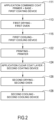
- Figure 2 depicts a block diagram of one embodiment of the invention for making a jet print on a strip.
- the beginning of the process sees the application of a double coat consisting of a primer and a base coat 111 in a single step. Subsequently, the combined coat 113 is dried and then cooled 115. Printing 122 is then executed on the coat. As in the state of the art, printing 122 is followed by the application of a clear coat 124 , its drying 126 and then its cooling 128. Cooling is by air and water. Idle support roller systems and deflectors can guide the strip towards the digital printing section.
- Each step is connected to a corresponding device adapted to perform that step, and precisely in this order: a first coating device for applying the combined coat; a first oven for drying the coat; a first cooling device; the printer; the second coating device for applying a clear coat, preferably with a roller applicator; a second oven; and a second cooling device.
- Figure 2 as Figure 1 , represents both the sequence of steps of an embodiment example of the process according to the invention and the order of the devices in an embodiment example of the plant according to the invention.
- a rough strip centring device 130 At the inlet of the printing unit 122 is a rough strip centring device 130 followed by an "S-like" bridle system 132 for controlling tension of the strip 134. Downstream there follows a fine strip centring device 136 and subsequently pass-line rollers 138 and deflectors (not shown) and a conveyor belt 140. Above the belt conveyor 140 is a plurality of digital inkjet print heads 142.
- An oven 144 for drying the ink then follows.
- a strip cooling system 146 is needed for cooling of the strip 134 .
- a probe 148 to measure the temperature of the strip is foreseen before the coating rollers that apply the clear coat ( Figure 2 ).
- the printer unit 122 ends with an additional "S-like" bridle system 150 at the output of the printing section to control the tension applied to the strip 134.
- a possible variant may provide for the addition of a strip position sensor 152 placed after the digital inkjet print heads 142. Said sensor measures the possible deviation of the strip 134 with respect to the centre of the line. In a further embodiment, the deviation measurement is sent to a control unit 154 that controls the transverse movement 156 of a slide (not shown) onto which the print heads 142 are mounted so as to compensate for any lateral displacement.
- the temperature of the strip measured by a temperature transducer 148 is sent to the line controller 154 which, in the event that the strip's 134 temperature exceeds what is considered to be the limit, intervenes by modifying the process speed and the capacity of the cooling system 146 so as to bring the strip's temperature 134 within the limits deemed acceptable.
- the control unit 154 manages the entire printing unit 122 and can, in this regard, be connected by cable to the individual elements, or else communicate telematically.
- a possible variant may provide for the measurement of the product/process quality parameters for both the top and bottom surfaces of the strip 134.
- the combined coat can be based on a polyester coating compatible with the subsequent application of the ink.
- the following sequence of layers may be created on the strip: a first layer based on a combined polyester-based coat with a thickness of about 5-10 ⁇ m; an ink layer with a thickness of about 0.5-3 ⁇ m; and, finally, a clear coat with a thickness of about 10-20 ⁇ m.
Landscapes
- Physics & Mathematics (AREA)
- Health & Medical Sciences (AREA)
- General Health & Medical Sciences (AREA)
- Thermal Sciences (AREA)
- Toxicology (AREA)
- Application Of Or Painting With Fluid Materials (AREA)
- Coating Apparatus (AREA)
- Ink Jet (AREA)
- Screen Printers (AREA)
- Printing Methods (AREA)
Claims (10)
- Eine Anlage zum Vorbeschichten und digitalen Tintenstrahldrucken eines Metallbandes (134), die in der folgenden Reihenfolge umfasst:(a) eine erste Beschichtungsvorrichtung (111) zum Auftragen einer kombinierten Schicht, die sowohl als Grundierung als auch als Basisschicht dient;(b) einen ersten Ofen (113) zum Trocknen der Beschichtung;(c) ein erstes Kühlsystem (115), beispielsweise ein Luft- und Wasserkühlsystem;(d) eine digitale Sol-Gel-Typ-Tintenstrahldruckeinheit (122), vorzugsweise mit einer Tintentrocknungsvorrichtung (146);(e) eine zweite Beschichtungsvorrichtung (124), insbesondere eine Walzenauftragsvorrichtung, zum Auftragen einer Klarlackschicht; (f) einen zweiten Ofen (126) zum Trocknen der Schicht; und(g) ein zweites Kühlsystem (128), beispielsweise ein Luft- und Wasserkühlsystem.
- Vorbeschichtungs- und Druckanlage nach Anspruch 1, dadurch gekennzeichnet, dass besagte Druckeinheit (122) in der folgenden Reihenfolge umfasst:(d-1) einen oder mehrere digitale Tintenstrahldruckköpfe vom Sol-Gel-Typ (142);(d-2) einen Tintentrockenofen (144);(d-3) ein drittes Kühlsystem (146);und dass stromaufwärts von besagtem einen oder den mehreren Druckköpfen (142) ein Zentriersystem (130, 136, 138) und ein erstes Bandspannungskontrollsystem (132) vorgesehen ist, das insbesondere in der folgenden Reihenfolge umfasst:(d-4) ein grobes Bandzentriersystem (130);(d-5) ein erstes "S"-förmiges Spannsystem (132) zur Steuerung der Bandspannung;(d-6) ein Feinband-Zentriersystem (136);(d-7) Durchlaufwalzen (138) und wahlweise Umlenkeinrichtungen;und dass hinter besagtem einen oder besagten mehreren Druckköpfen (142) ein zweites Bandspannungs-Steuerungssystem (150) vorgesehen ist, insbesondere:
(d-8) ein zweites "S-förmiges" Spann-System (150). - Anlage nach Anspruch 2, dadurch gekennzeichnet, dass sie ferner in der Druckeinheit einen Streifenpositionssensor (152) umfasst, und worin die Druckköpfe (142) auf einem Schlitten montiert sind, der sich orthogonal zur Bewegungsrichtung des Streifens bewegen kann, und worin die Anlage eine entsprechende Steuereinheit (154) umfasst, die so konfiguriert ist, dass sie die Bewegung des Schlittens gemäß den vom Positionssensor (152) erfassten Werten steuert, um die vom Positionssensor (152) gemessene seitliche Abweichung der Position des Streifens (134) auszugleichen.
- Anlage nach Anspruch 2 oder 3, dadurch gekennzeichnet, dass sie hinter der Druckeinheit (122) und vor der zweiten Beschichtungsvorrichtung (124) einen Bandtemperatursensor (148), insbesondere einen Temperaturwandler, umfasst, der geeignet ist, die Temperatur des Bandes (134) zu messen und den gemessenen Wert an eine entsprechende Steuereinheit (154) zu senden, die so konfiguriert ist, dass sie automatisch die Geschwindigkeit des Bandes (134) und/oder die Durchflussmenge des dritten Kühlsystems (146) steuert, um die vom Temperatursensor (148) gemessene Temperatur wieder auf vorgegebene Werte zu bringen.
- Verfahren zum Vorbeschichten und Bedrucken, insbesondere zum digitalen Tintenstrahldrucken, eines Metallbandes (134), das die folgenden Schritte in der angegebenen Reihenfolge umfasst:(I) Aufbringen einer kombinierten Schicht (111), die sowohl als Grundierung als auch als Basisschicht dient, auf ein Metallband (134);(II) Wärmetrocknung (113) der kombinierten Beschichtung;(III) Kühlen (115) der kombinierten Beschichtung;(IV) digitales Sol-Gel-Typ-Tintenstrahlbedrucken (122) des vorbeschichteten Streifens und vorzugsweise Trocknung der Tinte;(V) Aufbringen einer Klarlackschicht (124) auf den vorbeschichteten und bedruckten Streifen;(VI) Wärmetrocknung (126) der Klarlackschicht; und(VII) Kühlen der Klarlackschicht (128).
- Verfahren nach Anspruch 5, dadurch gekennzeichnet, dass das Band (134) vor Schritt (IV) zentriert wird und dass besagtes Band (134) vor und nach Schritt (IV) vorzugsweise gespannt wird, insbesondere mit einer Anlage nach Anspruch 2.
- Verfahren nach Anspruch 5 oder 6, dadurch gekennzeichnet, dass die kombinierte Beschichtung auf Polyester-Melamin basiert.
- Verfahren nach einem der Ansprüche 5 bis 7, dadurch gekennzeichnet, dass die Sol-Gel-Tinte ein thermisches Polymerisationsprodukt auf Silanbasis ist.
- Verfahren nach einem der Ansprüche 5 bis 8, dadurch gekennzeichnet, dass vor dem Schritt (IV) eine Messung der Position des Streifens (134) stattfindet und dass während des Schritts (IV) die Position des einen oder der mehreren Druckköpfe (142) eingestellt wird, um den Auftrag von Tinte auf den Streifen (134) auf der Grundlage der Messung der Position des Streifens zu optimieren.
- Verfahren nach einem der Ansprüche 5 bis 9, dadurch gekennzeichnet, dass nach dem Schritt (IV) die Temperatur des Bandes (134) überwacht wird und dass, wenn die Temperatur einen Grenzwert überschreitet, die Geschwindigkeit des Bandes (134) verlangsamt und/oder die Trocknung der Tinte verstärkt wird, um die Trocknung der Tinte vor dem Auftragen der Klarlackschicht (124) im Schritt (V) zu regulieren.
Applications Claiming Priority (2)
| Application Number | Priority Date | Filing Date | Title |
|---|---|---|---|
| IT102021000008324A IT202100008324A1 (it) | 2021-04-01 | 2021-04-01 | Impianto e procedimento per la stampa su nastri verniciati |
| PCT/IB2022/052994 WO2022208418A1 (en) | 2021-04-01 | 2022-03-31 | Plant and process for pre-coating and printing on metallic strips |
Publications (3)
| Publication Number | Publication Date |
|---|---|
| EP4313609A1 EP4313609A1 (de) | 2024-02-07 |
| EP4313609C0 EP4313609C0 (de) | 2024-11-13 |
| EP4313609B1 true EP4313609B1 (de) | 2024-11-13 |
Family
ID=76601588
Family Applications (1)
| Application Number | Title | Priority Date | Filing Date |
|---|---|---|---|
| EP22717009.9A Active EP4313609B1 (de) | 2021-04-01 | 2022-03-31 | Anlage und verfahren zum vorbeschichten und drucken auf metallbändern |
Country Status (9)
| Country | Link |
|---|---|
| US (1) | US20240359497A1 (de) |
| EP (1) | EP4313609B1 (de) |
| JP (1) | JP7662818B2 (de) |
| KR (1) | KR102877178B1 (de) |
| CN (1) | CN117279787A (de) |
| ES (1) | ES3000660T3 (de) |
| HU (1) | HUE069968T2 (de) |
| IT (1) | IT202100008324A1 (de) |
| WO (1) | WO2022208418A1 (de) |
Families Citing this family (2)
| Publication number | Priority date | Publication date | Assignee | Title |
|---|---|---|---|---|
| CN222291294U (zh) * | 2024-05-30 | 2025-01-03 | 佛山慧谷科技股份有限公司 | 一种人造石喷墨加工线 |
| CN119724764B (zh) * | 2025-02-28 | 2025-05-30 | 浙江应利成材料科技有限公司 | 一种用于漆包线底漆与面漆的均匀涂覆装置及工艺 |
Family Cites Families (17)
| Publication number | Priority date | Publication date | Assignee | Title |
|---|---|---|---|---|
| US5994264A (en) * | 1995-06-07 | 1999-11-30 | American Trim, Llc | Transfer printing of metal using protective overcoat |
| ITTO20030985A1 (it) * | 2003-12-09 | 2005-06-10 | Metlac S P A | Metodo per il trattamento superficiale di un supporto metallico, in particolare per l'imballaggio alimentare, e prodotto relativo. |
| US20070085983A1 (en) * | 2005-10-17 | 2007-04-19 | Photo Man Image Corporation | Digital ink jet printing process |
| JP5505592B2 (ja) * | 2009-01-29 | 2014-05-28 | セイコーエプソン株式会社 | 記録装置 |
| JP5630009B2 (ja) * | 2009-12-04 | 2014-11-26 | コニカミノルタ株式会社 | 活性光線硬化型インクジェット用インクおよびインクジェット記録方法 |
| US9046858B2 (en) * | 2012-12-27 | 2015-06-02 | Ricoh Company, Ltd. | Cooling device and image forming apparatus including same |
| EP3085632A4 (de) * | 2013-12-17 | 2017-08-16 | Toyo Seikan Co., Ltd. | Bedruckte folie für behälter und verfahren zur herstellung davon |
| JP6433868B2 (ja) * | 2015-09-02 | 2018-12-05 | 日新製鋼株式会社 | 塗装金属帯製造設備及びその方法 |
| DE102015118841A1 (de) * | 2015-11-03 | 2017-05-04 | Leonhard Kurz Stiftung & Co. Kg | Verfahren und Applikationsvorrichtung zum Applizieren einer Übertragungslage einer Folie auf ein Substrat |
| CN109844446B (zh) * | 2017-01-19 | 2022-09-30 | 惠普发展公司,有限责任合伙企业 | 打印机系统和用于测量打印介质的厚度的方法 |
| US10744756B2 (en) * | 2017-03-21 | 2020-08-18 | Ricoh Company, Ltd. | Conveyance device, conveyance system, and head unit control method |
| IT201800007488A1 (it) | 2018-07-25 | 2020-01-25 | Globus Srl | Gruppo di stampa per la stampa digitale su un nastro metallico continuo |
| JP7243215B2 (ja) * | 2019-01-23 | 2023-03-22 | コニカミノルタ株式会社 | インクジェット用の活性線硬化型インク、画像形成方法および画像形成装置 |
| US11416728B2 (en) * | 2019-08-15 | 2022-08-16 | Federal Card Services, LLC | Durable dual interface metal transaction cards |
| CN110588181B (zh) * | 2019-09-29 | 2020-11-27 | 南阳柯丽尔科技有限公司 | 胶片偏移的校正方法、装置及终端 |
| WO2022102058A1 (ja) * | 2020-11-12 | 2022-05-19 | コニカミノルタ株式会社 | インクジェット記録方法及びインクジェット記録装置 |
| EP4001366A1 (de) * | 2020-11-18 | 2022-05-25 | Helios Tovarna barv, lakovin umetnih smol Kolicevo D.o.o. | Reaktive sol-gel-tinte für digitalen druck |
-
2021
- 2021-04-01 IT IT102021000008324A patent/IT202100008324A1/it unknown
-
2022
- 2022-03-31 ES ES22717009T patent/ES3000660T3/es active Active
- 2022-03-31 HU HUE22717009A patent/HUE069968T2/hu unknown
- 2022-03-31 US US18/553,446 patent/US20240359497A1/en active Pending
- 2022-03-31 EP EP22717009.9A patent/EP4313609B1/de active Active
- 2022-03-31 JP JP2023560535A patent/JP7662818B2/ja active Active
- 2022-03-31 CN CN202280025343.6A patent/CN117279787A/zh active Pending
- 2022-03-31 WO PCT/IB2022/052994 patent/WO2022208418A1/en not_active Ceased
- 2022-03-31 KR KR1020237034966A patent/KR102877178B1/ko active Active
Also Published As
| Publication number | Publication date |
|---|---|
| US20240359497A1 (en) | 2024-10-31 |
| JP2024513398A (ja) | 2024-03-25 |
| IT202100008324A1 (it) | 2022-10-01 |
| HUE069968T2 (hu) | 2025-04-28 |
| EP4313609C0 (de) | 2024-11-13 |
| CN117279787A (zh) | 2023-12-22 |
| WO2022208418A1 (en) | 2022-10-06 |
| KR102877178B1 (ko) | 2025-10-28 |
| KR20230172477A (ko) | 2023-12-22 |
| JP7662818B2 (ja) | 2025-04-15 |
| ES3000660T3 (en) | 2025-03-03 |
| EP4313609A1 (de) | 2024-02-07 |
Similar Documents
| Publication | Publication Date | Title |
|---|---|---|
| EP1919711B1 (de) | Druckverfahren | |
| EP4313609B1 (de) | Anlage und verfahren zum vorbeschichten und drucken auf metallbändern | |
| US20060075917A1 (en) | Smooth finish UV ink system and method | |
| CN101480867A (zh) | 实现多色组定位冷烫转移印刷的方法 | |
| US5162141A (en) | Polymeric sheet having an incompatible ink permanently bonded thereto | |
| US20060075916A1 (en) | System and method for ink jet printing of water-based inks using aesthetically pleasing ink-receptive coatings | |
| EP4489974A1 (de) | Verfahren zur herstellung einer platte, platte, folie und verfahren zur herstellung einer folie | |
| US8979226B2 (en) | System and method for depositing solidifiable translucent fluid with a determined thickness | |
| JP2016182686A (ja) | 熱転写受像シート及び熱転写受像シートの製造方法 | |
| US7416297B2 (en) | Process and materials for marking plastic surfaces | |
| US6562178B1 (en) | Scratch-resistant, self-laminated printed materials and methods for making same | |
| EP1610957A1 (de) | Tintenstrahlaufzeichnungselemente und druckverfahren auf kunstoffoberflächen mit wässeriger tinte | |
| CN114558765A (zh) | 一种立体花纹防伪酒盖用铝板的生产工艺 | |
| JP3885980B2 (ja) | 転写シート | |
| US8780154B2 (en) | Controlling gloss in a solid ink jet print | |
| WO2021183706A1 (en) | Printing compositions and methods therefor | |
| JP2002363896A (ja) | 印刷効果を高めたシート及びその製造方法 | |
| CN117980151A (zh) | 用于产生纹理化的图像的印刷工艺 | |
| KR20250143342A (ko) | 장식용 라미네이트를 제조하는 시스템 및 방법 | |
| CN116137918A (zh) | 混合热转印标签组件 | |
| WO2007017896A2 (en) | Lacquer coated high-barrier laminates |
Legal Events
| Date | Code | Title | Description |
|---|---|---|---|
| STAA | Information on the status of an ep patent application or granted ep patent |
Free format text: STATUS: UNKNOWN |
|
| STAA | Information on the status of an ep patent application or granted ep patent |
Free format text: STATUS: THE INTERNATIONAL PUBLICATION HAS BEEN MADE |
|
| PUAI | Public reference made under article 153(3) epc to a published international application that has entered the european phase |
Free format text: ORIGINAL CODE: 0009012 |
|
| STAA | Information on the status of an ep patent application or granted ep patent |
Free format text: STATUS: REQUEST FOR EXAMINATION WAS MADE |
|
| 17P | Request for examination filed |
Effective date: 20231018 |
|
| AK | Designated contracting states |
Kind code of ref document: A1 Designated state(s): AL AT BE BG CH CY CZ DE DK EE ES FI FR GB GR HR HU IE IS IT LI LT LU LV MC MK MT NL NO PL PT RO RS SE SI SK SM TR |
|
| DAV | Request for validation of the european patent (deleted) | ||
| DAX | Request for extension of the european patent (deleted) | ||
| REG | Reference to a national code |
Ref country code: DE Ref legal event code: R079 Ipc: B41J0003413000 Ref country code: DE Ref legal event code: R079 Ref document number: 602022007736 Country of ref document: DE Free format text: PREVIOUS MAIN CLASS: B41M0005000000 Ipc: B41J0003413000 |
|
| GRAP | Despatch of communication of intention to grant a patent |
Free format text: ORIGINAL CODE: EPIDOSNIGR1 |
|
| STAA | Information on the status of an ep patent application or granted ep patent |
Free format text: STATUS: GRANT OF PATENT IS INTENDED |
|
| RIC1 | Information provided on ipc code assigned before grant |
Ipc: B41J 15/16 20060101ALI20240716BHEP Ipc: B41J 2/21 20060101ALI20240716BHEP Ipc: B41J 11/00 20060101ALI20240716BHEP Ipc: B41M 7/00 20060101ALI20240716BHEP Ipc: B41M 1/28 20060101ALI20240716BHEP Ipc: B41M 5/00 20060101ALI20240716BHEP Ipc: B41J 3/413 20060101AFI20240716BHEP |
|
| INTG | Intention to grant announced |
Effective date: 20240726 |
|
| GRAS | Grant fee paid |
Free format text: ORIGINAL CODE: EPIDOSNIGR3 |
|
| GRAA | (expected) grant |
Free format text: ORIGINAL CODE: 0009210 |
|
| STAA | Information on the status of an ep patent application or granted ep patent |
Free format text: STATUS: THE PATENT HAS BEEN GRANTED |
|
| AK | Designated contracting states |
Kind code of ref document: B1 Designated state(s): AL AT BE BG CH CY CZ DE DK EE ES FI FR GB GR HR HU IE IS IT LI LT LU LV MC MK MT NL NO PL PT RO RS SE SI SK SM TR |
|
| REG | Reference to a national code |
Ref country code: GB Ref legal event code: FG4D |
|
| REG | Reference to a national code |
Ref country code: CH Ref legal event code: EP |
|
| REG | Reference to a national code |
Ref country code: IE Ref legal event code: FG4D |
|
| REG | Reference to a national code |
Ref country code: DE Ref legal event code: R096 Ref document number: 602022007736 Country of ref document: DE |
|
| U01 | Request for unitary effect filed |
Effective date: 20241119 |
|
| U07 | Unitary effect registered |
Designated state(s): AT BE BG DE DK EE FI FR IT LT LU LV MT NL PT RO SE SI Effective date: 20241122 |
|
| REG | Reference to a national code |
Ref country code: SK Ref legal event code: T3 Ref document number: E 45591 Country of ref document: SK |
|
| REG | Reference to a national code |
Ref country code: ES Ref legal event code: FG2A Ref document number: 3000660 Country of ref document: ES Kind code of ref document: T3 Effective date: 20250303 |
|
| PG25 | Lapsed in a contracting state [announced via postgrant information from national office to epo] |
Ref country code: HR Free format text: LAPSE BECAUSE OF FAILURE TO SUBMIT A TRANSLATION OF THE DESCRIPTION OR TO PAY THE FEE WITHIN THE PRESCRIBED TIME-LIMIT Effective date: 20241113 Ref country code: IS Free format text: LAPSE BECAUSE OF FAILURE TO SUBMIT A TRANSLATION OF THE DESCRIPTION OR TO PAY THE FEE WITHIN THE PRESCRIBED TIME-LIMIT Effective date: 20250313 |
|
| PGFP | Annual fee paid to national office [announced via postgrant information from national office to epo] |
Ref country code: HU Payment date: 20250306 Year of fee payment: 4 |
|
| PG25 | Lapsed in a contracting state [announced via postgrant information from national office to epo] |
Ref country code: NO Free format text: LAPSE BECAUSE OF FAILURE TO SUBMIT A TRANSLATION OF THE DESCRIPTION OR TO PAY THE FEE WITHIN THE PRESCRIBED TIME-LIMIT Effective date: 20250213 |
|
| PG25 | Lapsed in a contracting state [announced via postgrant information from national office to epo] |
Ref country code: GR Free format text: LAPSE BECAUSE OF FAILURE TO SUBMIT A TRANSLATION OF THE DESCRIPTION OR TO PAY THE FEE WITHIN THE PRESCRIBED TIME-LIMIT Effective date: 20250214 |
|
| PG25 | Lapsed in a contracting state [announced via postgrant information from national office to epo] |
Ref country code: PL Free format text: LAPSE BECAUSE OF FAILURE TO SUBMIT A TRANSLATION OF THE DESCRIPTION OR TO PAY THE FEE WITHIN THE PRESCRIBED TIME-LIMIT Effective date: 20241113 |
|
| PGFP | Annual fee paid to national office [announced via postgrant information from national office to epo] |
Ref country code: SK Payment date: 20250304 Year of fee payment: 4 |
|
| REG | Reference to a national code |
Ref country code: HU Ref legal event code: AG4A Ref document number: E069968 Country of ref document: HU |
|
| PG25 | Lapsed in a contracting state [announced via postgrant information from national office to epo] |
Ref country code: RS Free format text: LAPSE BECAUSE OF FAILURE TO SUBMIT A TRANSLATION OF THE DESCRIPTION OR TO PAY THE FEE WITHIN THE PRESCRIBED TIME-LIMIT Effective date: 20250213 |
|
| PGFP | Annual fee paid to national office [announced via postgrant information from national office to epo] |
Ref country code: TR Payment date: 20250311 Year of fee payment: 4 |
|
| U20 | Renewal fee for the european patent with unitary effect paid |
Year of fee payment: 4 Effective date: 20250327 |
|
| PG25 | Lapsed in a contracting state [announced via postgrant information from national office to epo] |
Ref country code: SM Free format text: LAPSE BECAUSE OF FAILURE TO SUBMIT A TRANSLATION OF THE DESCRIPTION OR TO PAY THE FEE WITHIN THE PRESCRIBED TIME-LIMIT Effective date: 20241113 |
|
| PGFP | Annual fee paid to national office [announced via postgrant information from national office to epo] |
Ref country code: ES Payment date: 20250401 Year of fee payment: 4 |
|
| PG25 | Lapsed in a contracting state [announced via postgrant information from national office to epo] |
Ref country code: CZ Free format text: LAPSE BECAUSE OF FAILURE TO SUBMIT A TRANSLATION OF THE DESCRIPTION OR TO PAY THE FEE WITHIN THE PRESCRIBED TIME-LIMIT Effective date: 20241113 |
|
| PLBE | No opposition filed within time limit |
Free format text: ORIGINAL CODE: 0009261 |
|
| STAA | Information on the status of an ep patent application or granted ep patent |
Free format text: STATUS: NO OPPOSITION FILED WITHIN TIME LIMIT |
|
| PG25 | Lapsed in a contracting state [announced via postgrant information from national office to epo] |
Ref country code: MC Free format text: LAPSE BECAUSE OF FAILURE TO SUBMIT A TRANSLATION OF THE DESCRIPTION OR TO PAY THE FEE WITHIN THE PRESCRIBED TIME-LIMIT Effective date: 20241113 |
|
| 26N | No opposition filed |
Effective date: 20250814 |
|
| REG | Reference to a national code |
Ref country code: CH Ref legal event code: H13 Free format text: ST27 STATUS EVENT CODE: U-0-0-H10-H13 (AS PROVIDED BY THE NATIONAL OFFICE) Effective date: 20251023 |
|
| PG25 | Lapsed in a contracting state [announced via postgrant information from national office to epo] |
Ref country code: CH Free format text: LAPSE BECAUSE OF NON-PAYMENT OF DUE FEES Effective date: 20250331 |
|
| PG25 | Lapsed in a contracting state [announced via postgrant information from national office to epo] |
Ref country code: IE Free format text: LAPSE BECAUSE OF NON-PAYMENT OF DUE FEES Effective date: 20250331 |