EP4309557A2 - Filterpatrone für staubsauger - Google Patents
Filterpatrone für staubsauger Download PDFInfo
- Publication number
- EP4309557A2 EP4309557A2 EP23214843.7A EP23214843A EP4309557A2 EP 4309557 A2 EP4309557 A2 EP 4309557A2 EP 23214843 A EP23214843 A EP 23214843A EP 4309557 A2 EP4309557 A2 EP 4309557A2
- Authority
- EP
- European Patent Office
- Prior art keywords
- filter
- cartridge
- filter cartridge
- opening
- flap
- Prior art date
- Legal status (The legal status is an assumption and is not a legal conclusion. Google has not performed a legal analysis and makes no representation as to the accuracy of the status listed.)
- Granted
Links
Images


Classifications
-
- A—HUMAN NECESSITIES
- A47—FURNITURE; DOMESTIC ARTICLES OR APPLIANCES; COFFEE MILLS; SPICE MILLS; SUCTION CLEANERS IN GENERAL
- A47L—DOMESTIC WASHING OR CLEANING; SUCTION CLEANERS IN GENERAL
- A47L9/00—Details or accessories of suction cleaners, e.g. mechanical means for controlling the suction or for effecting pulsating action; Storing devices specially adapted to suction cleaners or parts thereof; Carrying-vehicles specially adapted for suction cleaners
- A47L9/10—Filters; Dust separators; Dust removal; Automatic exchange of filters
- A47L9/12—Dry filters
- A47L9/127—Dry filters tube- or sleeve-shaped
-
- A—HUMAN NECESSITIES
- A47—FURNITURE; DOMESTIC ARTICLES OR APPLIANCES; COFFEE MILLS; SPICE MILLS; SUCTION CLEANERS IN GENERAL
- A47L—DOMESTIC WASHING OR CLEANING; SUCTION CLEANERS IN GENERAL
- A47L9/00—Details or accessories of suction cleaners, e.g. mechanical means for controlling the suction or for effecting pulsating action; Storing devices specially adapted to suction cleaners or parts thereof; Carrying-vehicles specially adapted for suction cleaners
- A47L9/10—Filters; Dust separators; Dust removal; Automatic exchange of filters
- A47L9/14—Bags or the like; Rigid filtering receptacles; Attachment of, or closures for, bags or receptacles
- A47L9/1427—Means for mounting or attaching bags or filtering receptacles in suction cleaners; Adapters
- A47L9/1436—Connecting plates, e.g. collars, end closures
-
- B—PERFORMING OPERATIONS; TRANSPORTING
- B01—PHYSICAL OR CHEMICAL PROCESSES OR APPARATUS IN GENERAL
- B01D—SEPARATION
- B01D46/00—Filters or filtering processes specially modified for separating dispersed particles from gases or vapours
- B01D46/02—Particle separators, e.g. dust precipitators, having hollow filters made of flexible material
-
- B—PERFORMING OPERATIONS; TRANSPORTING
- B01—PHYSICAL OR CHEMICAL PROCESSES OR APPARATUS IN GENERAL
- B01D—SEPARATION
- B01D46/00—Filters or filtering processes specially modified for separating dispersed particles from gases or vapours
- B01D46/42—Auxiliary equipment or operation thereof
- B01D46/4272—Special valve constructions adapted to filters or filter elements
-
- B—PERFORMING OPERATIONS; TRANSPORTING
- B01—PHYSICAL OR CHEMICAL PROCESSES OR APPARATUS IN GENERAL
- B01D—SEPARATION
- B01D46/00—Filters or filtering processes specially modified for separating dispersed particles from gases or vapours
- B01D46/54—Particle separators, e.g. dust precipitators, using ultra-fine filter sheets or diaphragms
- B01D46/543—Particle separators, e.g. dust precipitators, using ultra-fine filter sheets or diaphragms using membranes
-
- F—MECHANICAL ENGINEERING; LIGHTING; HEATING; WEAPONS; BLASTING
- F16—ENGINEERING ELEMENTS AND UNITS; GENERAL MEASURES FOR PRODUCING AND MAINTAINING EFFECTIVE FUNCTIONING OF MACHINES OR INSTALLATIONS; THERMAL INSULATION IN GENERAL
- F16K—VALVES; TAPS; COCKS; ACTUATING-FLOATS; DEVICES FOR VENTING OR AERATING
- F16K15/00—Check valves
- F16K15/14—Check valves with flexible valve members
- F16K15/144—Check valves with flexible valve members the closure elements being fixed along all or a part of their periphery
- F16K15/145—Check valves with flexible valve members the closure elements being fixed along all or a part of their periphery the closure elements being shaped as a solids of revolution, e.g. cylindrical or conical
-
- B—PERFORMING OPERATIONS; TRANSPORTING
- B01—PHYSICAL OR CHEMICAL PROCESSES OR APPARATUS IN GENERAL
- B01D—SEPARATION
- B01D2265/00—Casings, housings or mounting for filters specially adapted for separating dispersed particles from gases or vapours
- B01D2265/04—Permanent measures for connecting different parts of the filter, e.g. welding, glueing or moulding
-
- B—PERFORMING OPERATIONS; TRANSPORTING
- B01—PHYSICAL OR CHEMICAL PROCESSES OR APPARATUS IN GENERAL
- B01D—SEPARATION
- B01D2265/00—Casings, housings or mounting for filters specially adapted for separating dispersed particles from gases or vapours
- B01D2265/06—Details of supporting structures for filtering material, e.g. cores
-
- B—PERFORMING OPERATIONS; TRANSPORTING
- B01—PHYSICAL OR CHEMICAL PROCESSES OR APPARATUS IN GENERAL
- B01D—SEPARATION
- B01D2271/00—Sealings for filters specially adapted for separating dispersed particles from gases or vapours
- B01D2271/02—Gaskets, sealings
-
- B—PERFORMING OPERATIONS; TRANSPORTING
- B01—PHYSICAL OR CHEMICAL PROCESSES OR APPARATUS IN GENERAL
- B01D—SEPARATION
- B01D2275/00—Filter media structures for filters specially adapted for separating dispersed particles from gases or vapours
- B01D2275/20—Shape of filtering material
- B01D2275/203—Shapes flexible in their geometry, e.g. bendable, adjustable to a certain size
-
- B—PERFORMING OPERATIONS; TRANSPORTING
- B01—PHYSICAL OR CHEMICAL PROCESSES OR APPARATUS IN GENERAL
- B01D—SEPARATION
- B01D2279/00—Filters adapted for separating dispersed particles from gases or vapours specially modified for specific uses
- B01D2279/55—Filters adapted for separating dispersed particles from gases or vapours specially modified for specific uses for cleaning appliances, e.g. suction cleaners
Definitions
- the present invention relates to the field of machines for cleaning, particularly vacuum cleaning devices.
- Typical machines include upright vacuum cleaners or canister/cylinder vacuum cleaners which have a wand or tube portion provided with a work head for cleaning various surfaces.
- a vacuum is created within a main body which provides a form of suction that collects dust and other small particles.
- the invention relates to a filter cartridge with a non-return valve for use in a vacuum cleaner, which may be collapsible to permit storage before use in a generally flat configuration.
- the filter bag can be difficult to orientate and fit into the vacuum cleaner.
- the bags must locate on at least one feature, which usually requires two hands to position. Removal of the filter bag is usually by hand, requiring the user to touch the bag during removal.
- Alternative vacuum cleaners operate using a bagless system, wherein the dust is contained within the vacuum cleaner without the use of a separate bag. In these types of vacuum cleaner, hair and long fibres can become entangled within the machine and require removal by hand or tool. Bagless vacuum cleaners often produce a dust "cloud" when being emptied.
- the present invention seeks to provide a filter cartridge for use in vacuum cleaners, which can be easily inserted into the vacuum cleaner and removed from the vacuum cleaner with minimal input from the user.
- the invention also seeks to provide a filter cartridge which minimize the escape of dust during unloading from the vacuum cleaning machine.
- a filter cartridge comprising:
- the filter cartridge has an opening provided through the first end wall for receiving air-entrained detritus into the interior, the opening being defined by the rigid support structure which spans and supports the first end wall of the cartridge.
- rigid we mean that it provides enough rigidity to support the filter cartridge shape without collapsing under its own weight or due to an applied vacuum suction.
- the rigid support structure of the first end wall of the filter cartridge comprises a central inner collar which defines the filter opening. There may also be an annular outer rim which defines a perimeter of the first end wall.
- the collar and rim portions of the rigid structure of the first end wall of the filter cartridge may be structurally attached/integrated as a unitary member.
- the rigid support structure may be provided by a spider member with multiple spokes or arms which provide a connecting means between the collar and the rim portions of the rigid support structure.
- the rigid support structure may comprise a generally annular member formed with a central bore defined by a collar.
- the member may have an inner dished (e.g. frustoconical) portion which is convex away from the cartridge interior.
- the member may have an outer dished portion (e.eg frustoconical) which is concave so that the inner dished portion is inset back into the cartridge.
- the collar may be coterminous with a rim of the body portion of the filter.
- a non-return valve is provided in the filter opening.
- non-return valve we mean that the valve allows fluid (gas) to be drawn through the filter opening into the filter cartridge, but which prevents (or limits) flow of matter (gas or collected detritus) back out through the opening.
- the non-return valve is provided with resilient constraint means which is adapted to adopt an open configuration in response to a threshold reduced pressure in the filter cartridge interior, and which closes, or substantially closes, when the pressure reverts to ambient.
- the non-return valve comprises a flap of material which can deflect between a closed position in which the flap blocks the filter opening and an open position in which the flap is deflected away from the open position and into the filter interior.
- a flap of material which can deflect between a closed position in which the flap blocks the filter opening and an open position in which the flap is deflected away from the open position and into the filter interior.
- the flap may be made of sheet plastics material, such as polypropylene, PVC, polyester or another similar resilient polymer material.
- the flap is preferably oriented so that in the closed position the flap is generally transverse with respect to the longitudinal axis of the filter cartridge, which axis extends between the end caps thereof.
- the flap In deflecting between closed and open positions, the flap may have an edge region which is fixed and a body portion which articulates or pivots with respect to the edge region.
- the pivot may be provided by an elongate seam or weakness (e.g. locally thinned neck region).
- the body portion of the flap may be sufficiently flexible to bend along its length in response to inward airflow into the cartridge.
- the edge region may be fixed to a portion of a collar which defines the filter opening.
- the flap may cantilever from the said collar portion to obturate the opening when undeflected.
- the flap typically comprises a planar web of flexible plastics material.
- Deflection-limiting stop or stops may be provided to limit the inward deflection of the flap or flaps.
- a shroud is provided around the filter opening, projecting inwardly into the filter interior from the collar which defines the opening.
- the shroud may have a generally horseshoe shape.
- the flap stop or stops may comprise one or more radially projecting nubs directed inwardly from the shroud inner surface. There may be two said nubs arranged to be diametrically opposed to one another.
- the filter cartridge may be provided with an annular flange around the outer circumference of the support structure.
- the rigid support structure is preferably generally annular in form.
- the support structure may be provided with a circumferential outer annular flange which renders the filter cartridge capable of being clamped between a rim and a lid of a vacuum chamber in which the filter cartridge may be located.
- the material for the cone facets or flap member material may comprise a transparent material. This allows a visual inspection to indicate whether the filter is full, even when the valve is closed.
- the rigid support structure of the filter cartridge may be provided with one or more seals operative between the filter cartridge opening and an inlet port of a vacuum chamber in which the cartridge is accommodated when in use.
- An inner seal may be provided at the inner collar region of the filter cartridge opening of the rigid support structure.
- the rigid support structure of the filter cartridge may be generally disc shaped and provided with a circumferential outer seal operative between the first end of the cartridge an internal wall of a cylindrical vacuum chamber in which the filter cartridge is accommodated when in use.
- the circumferential outer seal may be provided on an end face of the annular rim of the rigid support structure.
- the filter membrane material may be a single layer, or multilayer of filter material. This material is typically flexible, by which we mean flexible enough to be collapsed flat when handled.
- the filter cartridge may be collapsible, which is to say the body of the cartridge which defines the interior volume may be collapsed flat onto the rigid support structure.
- the filter membrane material or web may be generally planar, and does not rely upon repeated pleats or folds to prevent buckling or increase surface area.
- the filter membrane material of the filter cartridge may provide the side wall or walls of the cartridge.
- the filter membrane material of the filter cartridge may provide the second end wall of the cartridge.
- structural reinforcement may be provided on one or more of the sidewall or walls, and/or second end wall of the filter cartridge, so that the filter cartridge enclosure is self-supporting but collapsible, so that the cartridge may adopt an erect use configuration and in a collapsed configuration the side wall or walls and second end of the filter cartridge are drawn together onto the rigid support structure of the first end so as to be flat-packed.
- the structural reinforcement of the filter cartridge may act to bias the cartridge into the erect configuration, so that a collapsed cartridge will spontaneously adopt the erect configuration when a collapsing constraint is released.
- the filter cartridge may have a generally cylindrical configuration.
- the first and second end walls may have a generally disc-shaped configuration.
- a cylindrical side wall may extend between the first and second ends of the filter cartridge.
- the structural reinforcement of the filter cartridge may comprise one or more elongate seams joining filter membrane material portions.
- the seam may comprise overlapped, or pinched together, or butted together portions of filter membrane material.
- the portions of material may be joined by welding, such as ultrasonic welding, or fusion welding, or by adhesive such as hot melt adhesive.
- the structural reinforcement of the filter bag may comprise one or more resiliently flexible elongate struts, such as wire or plastic spines, which struts when elastically deformed during collapse may provide the erection bias.
- One or more of the seams of the filter cartridge may extend in the sidewall in an axial direction between the end walls. Alternatively, or in addition, the seams may extend helically around and along the sidewall between end walls.
- One or more strut(s) may be integrated into one or more seam of the filter bag. Alternatively, one or more strut(s) may be attached to the sidewall filter membrane material of the filter cartridge.
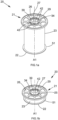
- a filter cartridge is shown generally as 20.
- the filter cartridge comprises a first end portion 21, a second end portion 22 and a body portion 23.
- the first end portion 21 comprises a spider 20 member 25, having eight cut out segments 26, a central opening 27 and a non-return valve 28 best seen in figure 2b .
- the spider member 25 of the first end portion 21 has an outer annular seal 29 having a C-section.
- the seal extends circumferentially about the central axis A1 of the disc shaped main body.
- the seal 29 is mounted onto an outer circumferential edge region 32 of the spider member 25 as shown in figure 2c .
- the seal 29 thereby provides an annular upper lip 31 and a corresponding lower annular lip 33 which protrudes from the underside of the spider member 25 as shown in figure 2c .
- a further annular seal 34 is provided around the opening 27 in the spider member (as shown in figure 1a ).
- the seal bead defines a rectangular sectioned lip 35 about the central axis A1 of the spider member 25.
- the protruding lips 31, 35 of the outer seal 29 and inner seal 34 provide a fluid seal when the filter is accommodated in the vacuum chamber of a vacuum cleaner (as shown in figure 9 for example) so that the suction air flow containing dust and small particles is directed into the filter cartridge 20 through the central opening 27 of the spider member 25.
- the central opening 27 of the spider member 25 provides an entry point for the dust and small particles drawn into the filter cartridge 20 by the vacuum cleaner during use.
- the opening 27 is defined by an annular collar 36.
- the collar extends from a bottom face 37 of the spider member 25 downwards into the main body 23 of the filter cartridge 20. Said collar assists in channelling the air flow into the filter cartridge 20 and provides a connecting face 38 for attachment of the non-return valve 28 to attach, as will be explained below.
- the connecting face 38 is the outer cylindrical face of the annular collar 36.
- the non-return valve 28 is a unitary moulded plastics member having a generally conical form and an annular collar 39.
- the collar 39 comprises an inner face 40 which is fixed (for example by adhesive) to the outer face 38 of the annular collar 36.
- the conical portion 41 depends from the annular collar 39 of the non-return valve 28.
- the conical portion is divided into a plurality of triangular segments 42 by radial slits 43 cut into the conical portion from the apex 44 of the conical portion to the collar.
- the non-return valve 28 is made from a polymer material which is flexibly resilient.
- the triangular segments 42 may each splay outwardly to an open configuration to form an orifice, in response to reduced pressure cause by a suction drive of the vacuum cleaner in which the filter cartridge is placed.
- air-entrained detritus may be drawn into the filter interior through the non-return valve.
- the segments flex back to the conical closed configuration. In this configuration the valve is closed so that escape of collected detritus is prevent or at least limited.
- the underside 37 of spider member 25 has adhered thereto an annular web of filter material 45.
- Said filter material has a central hole of diameter D ( figure 2c ).
- the outer diameter D5 of the filter material 45 is greater than the outside diameter D6 of the cut-out segments D7 in the spider member 25. The aforementioned sizing allows the filter material 45 cover the segments gaps 26.
- the body portion 23 of the filter cartridge is a web of flexible porous material.
- the body has a flared upper annular shoulder 47 which is fixed to the outer underside region of the annular web 45, typically by use of adhesive or welding.
- Figure 2b shows a section side section view A-A of the filter cartridge 20.
- the main body 23 of the filter cartridge 20 is made from a filter material.
- the filter material is structured to allow air to pass through, but to prevent the passing of dust and small particles collected during vacuum cleaning.
- the lower end portion 22 comprises a disc shaped base section 48 which closes the cylindrical body portion 23 of the filter cartridge 20.
- the base section of the body portion 23 has an annular flared shoulder region 51 which is fixed to a rim 49 of the base section 48 by way of a seam 50, shown in figure 2b .
- the filter material forms a complete enclosure for the collection of detritus which enters through the one-way conical valve.
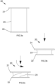
- the filter cartridge 20 In its first configuration, shown in figure 3a , the filter cartridge 20, is self-supported against buckling by the cylindrical shape and structure of the filter cartridge main body 23.
- the filter material 52 of the main body 23 may comprise a number of seams which join the filter material together, as will be described in more detail below.
- the filter may be collapsed by pushing down on the upper end 21 (per figure 3b ) or by twisting the upper end relative to the lower end 22 as per figure 3c .
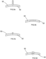
- Figures 5a to 5d show some of the options available for assembling the filter by joining the filter material. These comprise ultrasonic welding of abutting faces ( fig 5a ), ultrasonic welding of overlapping faces ( fig 5b ), adhesion of abutting edges using a bead of hot melt adhesive ( fig 5c ) and incorporation of elongate resilient reinforcement members in joined seams ( fig 5d ).
- the reinforcement members may comprise rods or ribbon struts, typically formed of metal or relatively rigid, but resiliently flexible, plastics material. These provide structural support for the cartridge, but also permit collapse of the cartridges under an applied axial or twisting pressure.
- FIG. 6a shows a single elongate longitudinally oriented seam
- figure 6b has two diametrically opposed elongate longitudinally extending seams
- figure 6c has three such seams
- figure 6d has a single helically extending seam
- figure 6e has two parallel helically extending seams.
- Figures 7a to 7e are side perspective view showing various structures and methods for collapsing the filter cartridge, in which the configuration of the expanded cartridges are shown in dashed lines.
- collapse is by axial pushing and twisting
- fig 7b the cartridge is folded until both end pieces are side-by-side
- fig 7c the cartridge upper end in simply pushed down in an axial direction (without twist)
- fig 7d the lower portion of the cartridge is rolled-up
- fig 7e a single seam extends for just over two complete turns and may be collapsed simply by axial compression in the direction A1.
- Figure 7e shows a method for collapsing the filter cartridge wherein the first end portion 21 is pushed towards the second end portion 22 along the central axis A1 of the filter cartridge 20.
- a double-coiled helical spring feature 54 is present in the filter cartridge main body 23 which travels from the first end 24 to the second end base section 48 within the structure of the filter material.
- the helical spring 54 is compressed as the first end portion 21 moves towards the second end portion 22 along the central axis A1 of the filter cartridge 20.
- the filter cartridge will be held in its second configuration, once the filter cartridge 20 is released from its second configuration, it will return naturally to its first, uncompressed configuration when the helical spring 54 decompresses.
- FIGS 8a and 8b show a filter cartridge 20 in accordance with the present invention, which is collapsed when the first end portion 21 is pushed towards the second end portion 22 along the central axis A1 of the filter cartridge 20, whilst the first end portion 21 is rotated about the central axis A1 of the filter cartridge 20.
- Said filter cartridge is supported by one or more straight struts 55 which travel the length of the filter cartridge body portion 23 from the first end 24 to the second end base 48.
- the vertical struts 55 are fixed to the filter cartridge main body 23.
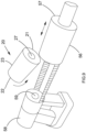
- FIGS 9 , 10a and 10b show schematically a filter cartridge 20 in accordance with the present invention in its first (expanded) configuration being inserted into a hand held vacuum cleaner 58 such that the filter cartridge sits horizontally in the vacuum cleaner.
- the filter cartridge is placed into the vacuum cleaner (arrow F in figure 10b ) such that the second end portion 22 of the filter cartridge 20 sits next to a suction air inlet 59 for a vacuum drive (not shown) of the cleaner.
- the vacuum cleaner comprises an open-ended chamber 56, which slides (arrow C in figure 10b ) over the filter cartridge 20 to the until an interior face of the end cap 57 abuts against the inner seal 34 and outer seal 29 of the first end portion 21 of the filter cartridge 20.
- the filter cartridge may be removed without touching the cartridge by axially shifting the chamber housing (as shown by the arrow R in figure 10a ), and then inverting the vacuum cleaner so that the cartridge falls away. This is useful when the collected dust may contaminated or hazardous.
- the filter body portion has a length which is less than the interior length of the vacuum chamber 56, and a diameter that is less than that of the chamber 65. This ensures a separation between the suction inlet orifice 59 and the filter end portion 22 and ensures that a lower pressure plenum is formed around the cartridge, in the annular space between filter body and chamber housing, when the suction motor is active.
- FIGs 11a to 11c show schematically an alternative arrangement of a handheld vacuum cleaner 60 in which the filter cartridge 20 in accordance with the present invention sits in a vertical orientation in a vacuum chamber 61.
- the chamber is fed by an elbow inlet pipe 63 in a lid 64 of the chamber.
- This inlet pipe is 5 fed by the nozzle tube 65.
- the lid may be opened (arrow in figure 11a ) to permit removal of the filter cartridge by manual vertical extraction, or by inverting the vacuum cleaner so that the cartridge drops out hands free.
- a filter cartridge in accordance with the invention is shown generally as 200 in figure 12 .
- the cartridge has a cylindrical body portion 201 formed of a filter membrane material suitable for vacuum cleaner use.
- the body portion has an elongate welded seam 202 extending in an axial direction.
- a distal end 203 of the cartridge (best seen in figure 15 ) comprises a flat disc of the filter membrane material, with a welded annular seam 204 formed by overlapping portions of the body portion distal edge and the outer region of the flat disc.
- a proximal end 205 of the filter cartridge is formed with as a unitary, generally annular support member 206 which is a moulding of plastics material.
- the support includes an inner frusto-conical portion 209 which tapers inwardly from an outer base region 210 to a central collar 207 around an inlet orifice 240.
- a rim 208 is provided around the collar, which serves as a sealing bead when the cartridge is placed inside a vacuum cleaner.
- the support From the outer base region 210 the support includes a portion 212 which flares outwardly to an annular outer flange feature 211.
- the filter cartridge is shown before loading into a handheld vacuum cleaner 220.
- the vacuum cleaner has a vacuum chamber 221 of generally cylindrical shape defined by a generally cylindrical housing 223.
- the chamber has a proximal end provided with a collar 222.
- a lower region of the collar is provided with a hinge 224 by which a lid member 225 is attached to the housing 223.
- the lid member has a circular, dished configuration and a central inlet orifice 226.
- An outer region of the lid member is provided with an inset semi-circular clamping member 227.
- the lid member is then closed by pivoting around the hinge 224.
- the outer edge of the lid member is held tightly against the flange feature 211 as the clamping member 227 is fastened to a retaining latch (not shown) on the upper edge of the collar 222.
- the central inlet orifice 226 of the lid member will receive one end of an elongate tubular nozzle (not shown), which (during use) will transport air-entrained detritus into the interior of the cartridge via the collar 207, induced by a suction drive 228 provided at a distal end of the vacuum cleaner.
- FIG. 14a and 14b the distal side of the support member 206 is shown.
- a sectioned support member is shown in figure 14c .
- a shroud member 230 having a generally horse-shoe shape is shown surrounding the central collar 207 of the support.
- a chord feature 229 of the collar 207 is best seen in figure 15 .
- the chord feature provided a flat edge region to the collar inner edge.
- Three spaced apart studs 231 are provided along the chord feature.
- a transparent planar flap member 232 has the shape shown in figure 15 which corresponds to the inner shape of the collar 227.
- Three spaced apart bores 233 are provided along one edge region of the flap member. Projecting out from the said one edge region is a tongue feature 234.
- the flap member is placed over the three studs 213 with the bores receiving the studs. The studs are then heat pressed to fix the flap member in place.
- the tongue feature sits in a complementary shaped inset wedge 235.
- the flap member acts as a cantilever closure which, at rest, obturates the inlet orifice 240.
- a vacuum suction is applied to the vacuum chamber 224, the airflow into the filter cartridge through the orifice 240 causes the flap member to bend inwards, as shown in figures 14b and 14c .
- Two radially directed nubs 241, 242 ore provided diametrically opposed to one another on the inside of the shroud 230. These nubs serve as stops to the inward deflection of the flap member.
- the shroud serves to help prevent egress of detritus in the filter cartridge interior via the inlet orifice by blocking radial travel of particles towards the collar, especially when the cartridge interior is almost full.
- the present invention relates to a filter cartridge for a vacuum cleaner comprising first and second opposite end walls, a side wall or walls which extend between the end walls so as to define an enclosure which surrounds a filter interior, wherein one or more of the walls comprises filter membrane material, the cartridge having an opening provided through the first end wall for receiving air-entrained detritus into the interior, the opening being defined by a rigid support structure which spans and supports the first end wall of the cartridge.
- the cartridge includes a non-return valve which closes when suction is removed so as to help prevent collected detritus escaping from the filter cartridge interior.
- the valve may comprises a cantilevered flap.
Landscapes
- Engineering & Computer Science (AREA)
- Mechanical Engineering (AREA)
- Chemical & Material Sciences (AREA)
- Chemical Kinetics & Catalysis (AREA)
- General Engineering & Computer Science (AREA)
- Filtering Of Dispersed Particles In Gases (AREA)
- Filters For Electric Vacuum Cleaners (AREA)
Applications Claiming Priority (3)
| Application Number | Priority Date | Filing Date | Title |
|---|---|---|---|
| GB1902895.0A GB2581969A (en) | 2019-03-04 | 2019-03-04 | Collapsible filter cartridge |
| PCT/GB2020/050504 WO2020178573A1 (en) | 2019-03-04 | 2020-03-03 | Vacuum cleaner filter cartridge |
| EP20709691.8A EP3934501B1 (de) | 2019-03-04 | 2020-03-03 | Staubsauger-filterpatrone |
Related Parent Applications (2)
| Application Number | Title | Priority Date | Filing Date |
|---|---|---|---|
| EP20709691.8A Division EP3934501B1 (de) | 2019-03-04 | 2020-03-03 | Staubsauger-filterpatrone |
| EP20709691.8A Division-Into EP3934501B1 (de) | 2019-03-04 | 2020-03-03 | Staubsauger-filterpatrone |
Publications (4)
| Publication Number | Publication Date |
|---|---|
| EP4309557A2 true EP4309557A2 (de) | 2024-01-24 |
| EP4309557A3 EP4309557A3 (de) | 2024-04-24 |
| EP4309557C0 EP4309557C0 (de) | 2024-09-18 |
| EP4309557B1 EP4309557B1 (de) | 2024-09-18 |
Family
ID=66377284
Family Applications (2)
| Application Number | Title | Priority Date | Filing Date |
|---|---|---|---|
| EP20709691.8A Active EP3934501B1 (de) | 2019-03-04 | 2020-03-03 | Staubsauger-filterpatrone |
| EP23214843.7A Active EP4309557B1 (de) | 2019-03-04 | 2020-03-03 | Filterpatrone für staubsauger |
Family Applications Before (1)
| Application Number | Title | Priority Date | Filing Date |
|---|---|---|---|
| EP20709691.8A Active EP3934501B1 (de) | 2019-03-04 | 2020-03-03 | Staubsauger-filterpatrone |
Country Status (7)
| Country | Link |
|---|---|
| US (2) | US11950749B2 (de) |
| EP (2) | EP3934501B1 (de) |
| CN (1) | CN114007478B (de) |
| ES (2) | ES2991034T3 (de) |
| GB (1) | GB2581969A (de) |
| PL (2) | PL3934501T3 (de) |
| WO (1) | WO2020178573A1 (de) |
Families Citing this family (8)
| Publication number | Priority date | Publication date | Assignee | Title |
|---|---|---|---|---|
| US11672395B2 (en) * | 2021-01-06 | 2023-06-13 | Omachron Intellectual Property Inc. | Surface cleaning apparatus |
| GB2581969A (en) * | 2019-03-04 | 2020-09-09 | Numatic Int Ltd | Collapsible filter cartridge |
| JP1679793S (de) * | 2020-03-25 | 2021-04-19 | ||
| JP1679792S (de) * | 2020-03-25 | 2021-04-19 | ||
| PL4199795T3 (pl) * | 2020-08-20 | 2024-10-28 | Aktiebolaget Electrolux | Kompaktowy worek na kurz do odkurzacza |
| CN113559639B (zh) * | 2021-08-20 | 2023-08-04 | 深圳市晨北科技有限公司 | 过滤装置 |
| USD1053488S1 (en) * | 2023-06-19 | 2024-12-03 | Chengwen Zeng | Screen cleaner |
| USD1060910S1 (en) * | 2023-08-01 | 2025-02-04 | Hangzhou Tanlink Technology Co., Ltd | Screen cleaner |
Family Cites Families (44)
| Publication number | Priority date | Publication date | Assignee | Title |
|---|---|---|---|---|
| US2564339A (en) | 1950-05-06 | 1951-08-14 | Lawrence F Nerheim | Vacuum cleaner |
| US3627115A (en) * | 1969-06-16 | 1971-12-14 | Tenneco Inc | Transparent filter package |
| FI47592C (fi) * | 1969-06-26 | 1974-01-10 | Waertsilae Oy Ab | Vesiklosetin huuhtelusäiliön täyttölaite. |
| CA1121693A (en) * | 1980-01-04 | 1982-04-13 | Robert A. Ritter | Back pressure regulator and non-return valve |
| US4426062A (en) * | 1982-02-10 | 1984-01-17 | Black & Decker Inc. | Fluid flow control valves |
| US5297311A (en) | 1992-05-04 | 1994-03-29 | Citywide Machine Wholesale, Inc. | Vacuum cleaner |
| GB2314031B (en) * | 1996-06-10 | 1999-12-15 | Fram Europ | Fluid filter element and method of manufacture |
| US5855634A (en) * | 1997-06-24 | 1999-01-05 | Shop Vac Corporation | Filter retainer for a vacuum cleaner |
| FR2776908B1 (fr) | 1998-04-02 | 2000-06-09 | Seb Sa | Appareil electrique recuperateur de dechets |
| CN1360668A (zh) * | 1999-06-15 | 2002-07-24 | 艾普万有限公司 | 单向阀 |
| JP2002206576A (ja) | 2001-01-12 | 2002-07-26 | Nissin Kogyo Co Ltd | 機械式車両用ディスクブレーキ |
| FI113395B (fi) * | 2001-05-03 | 2004-04-15 | Evac Int Oy | Venttiilielin |
| KR20030035629A (ko) * | 2001-11-01 | 2003-05-09 | (주)휴먼앤휴먼테크놀러지 | 무선 진공청소기용 집진필터의 착탈구조 |
| EP1539031B1 (de) * | 2002-09-19 | 2013-01-02 | Memory Metal Holland BV | Gefässfilter mit verbesserter festigkeit und flexibilität |
| KR20040043384A (ko) | 2002-11-18 | 2004-05-24 | 삼성광주전자 주식회사 | 진공청소기용 필터 |
| KR100456167B1 (ko) | 2002-11-22 | 2004-11-09 | 삼성광주전자 주식회사 | 진공청소기용 집진필터 및 이를 구비하는 진공청소기 |
| DE10311501B4 (de) * | 2003-03-15 | 2011-06-16 | Neoperl Gmbh | Einbauteil zum Einsetzen in eine Gas- oder Flüssigkeitsleitung |
| CN1284502C (zh) * | 2004-02-12 | 2006-11-15 | 胡海荣 | 用于吸尘器的灰尘收集装置 |
| DE502005005027D1 (de) * | 2004-02-17 | 2008-09-25 | Ehrfeld Mikrotechnik Bts Gmbh | Mikromischer |
| JP2007114513A (ja) * | 2005-10-20 | 2007-05-10 | Kyocera Mita Corp | 塵回収容器、トナー回収容器、画像形成装置および掃除機 |
| US8585753B2 (en) * | 2006-03-04 | 2013-11-19 | John James Scanlon | Fibrillated biodegradable prosthesis |
| JP4699340B2 (ja) * | 2006-11-16 | 2011-06-08 | 日東電工株式会社 | フィルタユニット |
| US20080148511A1 (en) * | 2006-12-22 | 2008-06-26 | Brown Michael O | Pest collecting vacuum |
| EP1992400A1 (de) * | 2007-05-18 | 2008-11-19 | Vlaamse Instelling Voor Technologisch Onderzoek (Vito) | Membranbeutel und Verfahren zu dessen Herstellung |
| US20080127832A1 (en) * | 2008-02-23 | 2008-06-05 | Yuejie Zhang | Transparent Foldable Dust Bag |
| US8066433B2 (en) | 2008-03-14 | 2011-11-29 | Pro-Mart Industries, Inc. | Valve for vacuum storage bag |
| GB2459300B (en) | 2008-04-18 | 2010-03-10 | Black & Decker Inc | Vacuum cleaner |
| DE102008049627A1 (de) * | 2008-09-30 | 2010-04-08 | Mann + Hummel Gmbh | Verfahren zum Herstellen einer Filterendscheibe und eines Fluidfilters, Kraftfahrzeugfluidfilter |
| JP2010125052A (ja) * | 2008-11-27 | 2010-06-10 | Toshiba Corp | 掃除機用集塵袋及び電気掃除機 |
| WO2012152695A1 (en) * | 2011-05-06 | 2012-11-15 | Sanofi-Aventis Deutschland Gmbh | Flexible valve geometry for the use of rigid materials |
| ITBS20110129A1 (it) * | 2011-09-26 | 2013-03-27 | Capitani Srl | Capsula per la produzione di una bevanda infusa |
| GB2507313B (en) * | 2012-10-25 | 2015-09-30 | Tristel Plc | Pump apparatus |
| AT513571B1 (de) * | 2012-11-13 | 2014-08-15 | Aqa Gmbh | Vorrichtung zum Sammeln von Aerosolpartikeln aus der Luft |
| FR3027292B1 (fr) * | 2014-10-17 | 2016-12-23 | Oreal | Dispositif de distribution d'un produit cosmetique sous forme aerosol, ensemble et procede associes |
| DE102014119190A1 (de) * | 2014-12-19 | 2016-06-23 | Vorwerk & Co. Interholding Gmbh | Saugdüse für einen elektromotorisch betriebenen Staubsauger |
| KR102283479B1 (ko) * | 2016-04-28 | 2021-07-29 | 엔테그리스, 아이엔씨. | 가연성 필터 카트리지 및 재사용가능한 프레임을 갖는 공기중 분자 오염 필터 카트리지 시스템 |
| GB2569821B (en) | 2017-12-30 | 2020-04-29 | Dyson Technology Ltd | A cleaning appliance |
| WO2019240254A1 (ja) * | 2018-06-15 | 2019-12-19 | 富士フイルム株式会社 | 親水性多孔質膜および親水性多孔質膜の製造方法 |
| CN113164880A (zh) * | 2018-11-30 | 2021-07-23 | 富士胶片株式会社 | 多孔膜的制造方法及多孔膜 |
| CN113474078B (zh) * | 2019-02-26 | 2023-05-30 | 富士胶片株式会社 | 亲水性多孔膜及亲水性多孔膜的制造方法 |
| GB2581969A (en) * | 2019-03-04 | 2020-09-09 | Numatic Int Ltd | Collapsible filter cartridge |
| GB201902894D0 (en) * | 2019-03-04 | 2019-04-17 | Numatic Int Ltd | Vacuum cleaner |
| JP7177016B2 (ja) * | 2019-07-24 | 2022-11-22 | 富士フイルム株式会社 | 多孔質膜およびフィルターカートリッジ |
| US11918946B2 (en) * | 2019-09-19 | 2024-03-05 | Re-U-Zip, LLC | Portable air filtration system |
-
2019
- 2019-03-04 GB GB1902895.0A patent/GB2581969A/en not_active Withdrawn
-
2020
- 2020-03-03 EP EP20709691.8A patent/EP3934501B1/de active Active
- 2020-03-03 CN CN202080026814.6A patent/CN114007478B/zh active Active
- 2020-03-03 PL PL20709691.8T patent/PL3934501T3/pl unknown
- 2020-03-03 WO PCT/GB2020/050504 patent/WO2020178573A1/en not_active Ceased
- 2020-03-03 ES ES23214843T patent/ES2991034T3/es active Active
- 2020-03-03 US US17/435,341 patent/US11950749B2/en active Active
- 2020-03-03 EP EP23214843.7A patent/EP4309557B1/de active Active
- 2020-03-03 PL PL23214843.7T patent/PL4309557T3/pl unknown
- 2020-03-03 ES ES20709691T patent/ES2980454T3/es active Active
-
2024
- 2024-01-30 US US18/427,550 patent/US12193628B2/en active Active
Also Published As
| Publication number | Publication date |
|---|---|
| CN114007478A (zh) | 2022-02-01 |
| GB2581969A (en) | 2020-09-09 |
| ES2991034T3 (es) | 2024-12-02 |
| EP3934501A1 (de) | 2022-01-12 |
| ES2980454T3 (es) | 2024-10-01 |
| EP4309557C0 (de) | 2024-09-18 |
| US12193628B2 (en) | 2025-01-14 |
| EP4309557B1 (de) | 2024-09-18 |
| WO2020178573A1 (en) | 2020-09-10 |
| US11950749B2 (en) | 2024-04-09 |
| US20220133107A1 (en) | 2022-05-05 |
| EP4309557A3 (de) | 2024-04-24 |
| EP3934501C0 (de) | 2024-05-08 |
| PL4309557T3 (pl) | 2025-02-10 |
| CN114007478B (zh) | 2023-07-21 |
| PL3934501T3 (pl) | 2024-09-09 |
| EP3934501B1 (de) | 2024-05-08 |
| US20240164601A1 (en) | 2024-05-23 |
| GB201902895D0 (en) | 2019-04-17 |
Similar Documents
| Publication | Publication Date | Title |
|---|---|---|
| US12193628B2 (en) | Vacuum cleaner filter cartridge | |
| US6193787B1 (en) | Domestic vacuum cleaner and an attachment therefor | |
| CN109310940B (zh) | 真空过滤器 | |
| US8424154B2 (en) | Vacuum cleaner with filter cleaning means | |
| EP1681099B1 (de) | Zyklonabscheider für Staubsauger | |
| CN102406486B (zh) | 用于真空清洁器具的过滤器组件 | |
| US6428589B1 (en) | Two-stage particle separator for vacuum cleaners | |
| US20010047721A1 (en) | Vacuum collection bag and method of operation | |
| WO1998010691B1 (en) | A domestic vacuum cleaner and an attachment therefor | |
| US20100229512A1 (en) | Multi-layer particle collector assembly | |
| JPH06159178A (ja) | 吸い込みヘッド | |
| JP3913272B2 (ja) | 表面清掃あるいは乾燥に用いる液体除去器具およびこれに使用される集液容器 | |
| US20060117723A1 (en) | Cyclone dust-separating apparatus | |
| US20080127832A1 (en) | Transparent Foldable Dust Bag | |
| JPH02224724A (ja) | タンク式電気掃除機用吸気シール | |
| US2237499A (en) | Vacuum-cleaner bag | |
| JP2003310507A (ja) | 集塵装置およびこの集塵装置が組み込まれた電気掃除機 | |
| JP2003024826A (ja) | 回収袋付きサイクロン分離装置 | |
| US7611559B2 (en) | Filter element | |
| US20220125259A1 (en) | Unopenable canister for vacuum cleaner | |
| WO2003086581A1 (en) | A filter bag and a filter device provided with such filter bag | |
| WO2001078571A1 (en) | Dust container | |
| JP5816009B2 (ja) | フレキシブルコンテナの形成方法 | |
| US20030208998A1 (en) | Filter bag and method of manufacture thereof | |
| CN105996901B (zh) | 用于吸尘器的过滤器及其使用方法和吸尘器 |
Legal Events
| Date | Code | Title | Description |
|---|---|---|---|
| PUAI | Public reference made under article 153(3) epc to a published international application that has entered the european phase |
Free format text: ORIGINAL CODE: 0009012 |
|
| STAA | Information on the status of an ep patent application or granted ep patent |
Free format text: STATUS: REQUEST FOR EXAMINATION WAS MADE |
|
| 17P | Request for examination filed |
Effective date: 20231207 |
|
| AC | Divisional application: reference to earlier application |
Ref document number: 3934501 Country of ref document: EP Kind code of ref document: P |
|
| AK | Designated contracting states |
Kind code of ref document: A2 Designated state(s): AL AT BE BG CH CY CZ DE DK EE ES FI FR GB GR HR HU IE IS IT LI LT LU LV MC MK MT NL NO PL PT RO RS SE SI SK SM TR |
|
| PUAL | Search report despatched |
Free format text: ORIGINAL CODE: 0009013 |
|
| AK | Designated contracting states |
Kind code of ref document: A3 Designated state(s): AL AT BE BG CH CY CZ DE DK EE ES FI FR GB GR HR HU IE IS IT LI LT LU LV MC MK MT NL NO PL PT RO RS SE SI SK SM TR |
|
| RIC1 | Information provided on ipc code assigned before grant |
Ipc: A47L 9/00 20060101ALN20240319BHEP Ipc: A47L 9/12 20060101AFI20240319BHEP |
|
| GRAP | Despatch of communication of intention to grant a patent |
Free format text: ORIGINAL CODE: EPIDOSNIGR1 |
|
| STAA | Information on the status of an ep patent application or granted ep patent |
Free format text: STATUS: GRANT OF PATENT IS INTENDED |
|
| RIC1 | Information provided on ipc code assigned before grant |
Ipc: A47L 9/00 20060101ALN20240409BHEP Ipc: A47L 9/12 20060101AFI20240409BHEP |
|
| INTG | Intention to grant announced |
Effective date: 20240503 |
|
| GRAS | Grant fee paid |
Free format text: ORIGINAL CODE: EPIDOSNIGR3 |
|
| GRAA | (expected) grant |
Free format text: ORIGINAL CODE: 0009210 |
|
| STAA | Information on the status of an ep patent application or granted ep patent |
Free format text: STATUS: THE PATENT HAS BEEN GRANTED |
|
| AC | Divisional application: reference to earlier application |
Ref document number: 3934501 Country of ref document: EP Kind code of ref document: P |
|
| AK | Designated contracting states |
Kind code of ref document: B1 Designated state(s): AL AT BE BG CH CY CZ DE DK EE ES FI FR GB GR HR HU IE IS IT LI LT LU LV MC MK MT NL NO PL PT RO RS SE SI SK SM TR |
|
| REG | Reference to a national code |
Ref country code: GB Ref legal event code: FG4D |
|
| REG | Reference to a national code |
Ref country code: CH Ref legal event code: EP |
|
| REG | Reference to a national code |
Ref country code: IE Ref legal event code: FG4D |
|
| REG | Reference to a national code |
Ref country code: DE Ref legal event code: R096 Ref document number: 602020038176 Country of ref document: DE |
|
| U01 | Request for unitary effect filed |
Effective date: 20240919 |
|
| U07 | Unitary effect registered |
Designated state(s): AT BE BG DE DK EE FI FR IT LT LU LV MT NL PT RO SE SI Effective date: 20241011 |
|
| REG | Reference to a national code |
Ref country code: ES Ref legal event code: FG2A Ref document number: 2991034 Country of ref document: ES Kind code of ref document: T3 Effective date: 20241202 |
|
| PG25 | Lapsed in a contracting state [announced via postgrant information from national office to epo] |
Ref country code: NO Free format text: LAPSE BECAUSE OF FAILURE TO SUBMIT A TRANSLATION OF THE DESCRIPTION OR TO PAY THE FEE WITHIN THE PRESCRIBED TIME-LIMIT Effective date: 20241218 |
|
| PG25 | Lapsed in a contracting state [announced via postgrant information from national office to epo] |
Ref country code: GR Free format text: LAPSE BECAUSE OF FAILURE TO SUBMIT A TRANSLATION OF THE DESCRIPTION OR TO PAY THE FEE WITHIN THE PRESCRIBED TIME-LIMIT Effective date: 20241219 |
|
| PG25 | Lapsed in a contracting state [announced via postgrant information from national office to epo] |
Ref country code: HR Free format text: LAPSE BECAUSE OF FAILURE TO SUBMIT A TRANSLATION OF THE DESCRIPTION OR TO PAY THE FEE WITHIN THE PRESCRIBED TIME-LIMIT Effective date: 20240918 |
|
| PG25 | Lapsed in a contracting state [announced via postgrant information from national office to epo] |
Ref country code: RS Free format text: LAPSE BECAUSE OF FAILURE TO SUBMIT A TRANSLATION OF THE DESCRIPTION OR TO PAY THE FEE WITHIN THE PRESCRIBED TIME-LIMIT Effective date: 20241218 |
|
| PG25 | Lapsed in a contracting state [announced via postgrant information from national office to epo] |
Ref country code: RS Free format text: LAPSE BECAUSE OF FAILURE TO SUBMIT A TRANSLATION OF THE DESCRIPTION OR TO PAY THE FEE WITHIN THE PRESCRIBED TIME-LIMIT Effective date: 20241218 Ref country code: NO Free format text: LAPSE BECAUSE OF FAILURE TO SUBMIT A TRANSLATION OF THE DESCRIPTION OR TO PAY THE FEE WITHIN THE PRESCRIBED TIME-LIMIT Effective date: 20241218 Ref country code: HR Free format text: LAPSE BECAUSE OF FAILURE TO SUBMIT A TRANSLATION OF THE DESCRIPTION OR TO PAY THE FEE WITHIN THE PRESCRIBED TIME-LIMIT Effective date: 20240918 Ref country code: GR Free format text: LAPSE BECAUSE OF FAILURE TO SUBMIT A TRANSLATION OF THE DESCRIPTION OR TO PAY THE FEE WITHIN THE PRESCRIBED TIME-LIMIT Effective date: 20241219 |
|
| PG25 | Lapsed in a contracting state [announced via postgrant information from national office to epo] |
Ref country code: IS Free format text: LAPSE BECAUSE OF FAILURE TO SUBMIT A TRANSLATION OF THE DESCRIPTION OR TO PAY THE FEE WITHIN THE PRESCRIBED TIME-LIMIT Effective date: 20250118 |
|
| PG25 | Lapsed in a contracting state [announced via postgrant information from national office to epo] |
Ref country code: SM Free format text: LAPSE BECAUSE OF FAILURE TO SUBMIT A TRANSLATION OF THE DESCRIPTION OR TO PAY THE FEE WITHIN THE PRESCRIBED TIME-LIMIT Effective date: 20240918 |
|
| PG25 | Lapsed in a contracting state [announced via postgrant information from national office to epo] |
Ref country code: CZ Free format text: LAPSE BECAUSE OF FAILURE TO SUBMIT A TRANSLATION OF THE DESCRIPTION OR TO PAY THE FEE WITHIN THE PRESCRIBED TIME-LIMIT Effective date: 20240918 |
|
| PGFP | Annual fee paid to national office [announced via postgrant information from national office to epo] |
Ref country code: PL Payment date: 20250227 Year of fee payment: 6 |
|
| PG25 | Lapsed in a contracting state [announced via postgrant information from national office to epo] |
Ref country code: SK Free format text: LAPSE BECAUSE OF FAILURE TO SUBMIT A TRANSLATION OF THE DESCRIPTION OR TO PAY THE FEE WITHIN THE PRESCRIBED TIME-LIMIT Effective date: 20240918 |
|
| U20 | Renewal fee for the european patent with unitary effect paid |
Year of fee payment: 6 Effective date: 20250328 |
|
| PGFP | Annual fee paid to national office [announced via postgrant information from national office to epo] |
Ref country code: ES Payment date: 20250401 Year of fee payment: 6 |
|
| PGFP | Annual fee paid to national office [announced via postgrant information from national office to epo] |
Ref country code: CH Payment date: 20250401 Year of fee payment: 6 |
|
| PLBE | No opposition filed within time limit |
Free format text: ORIGINAL CODE: 0009261 |
|
| STAA | Information on the status of an ep patent application or granted ep patent |
Free format text: STATUS: NO OPPOSITION FILED WITHIN TIME LIMIT |
|
| 26N | No opposition filed |
Effective date: 20250619 |
|
| PG25 | Lapsed in a contracting state [announced via postgrant information from national office to epo] |
Ref country code: MC Free format text: LAPSE BECAUSE OF FAILURE TO SUBMIT A TRANSLATION OF THE DESCRIPTION OR TO PAY THE FEE WITHIN THE PRESCRIBED TIME-LIMIT Effective date: 20240918 |
|
| PG25 | Lapsed in a contracting state [announced via postgrant information from national office to epo] |
Ref country code: IE Free format text: LAPSE BECAUSE OF NON-PAYMENT OF DUE FEES Effective date: 20250303 |
|
| PGFP | Annual fee paid to national office [announced via postgrant information from national office to epo] |
Ref country code: GB Payment date: 20260330 Year of fee payment: 7 |