EP4306736B1 - Trennwand - Google Patents
Trennwand Download PDFInfo
- Publication number
- EP4306736B1 EP4306736B1 EP22795670.3A EP22795670A EP4306736B1 EP 4306736 B1 EP4306736 B1 EP 4306736B1 EP 22795670 A EP22795670 A EP 22795670A EP 4306736 B1 EP4306736 B1 EP 4306736B1
- Authority
- EP
- European Patent Office
- Prior art keywords
- air
- blow
- partition
- out port
- air passage
- Prior art date
- Legal status (The legal status is an assumption and is not a legal conclusion. Google has not performed a legal analysis and makes no representation as to the accuracy of the status listed.)
- Active
Links
Images





Classifications
-
- A—HUMAN NECESSITIES
- A47—FURNITURE; DOMESTIC ARTICLES OR APPLIANCES; COFFEE MILLS; SPICE MILLS; SUCTION CLEANERS IN GENERAL
- A47G—HOUSEHOLD OR TABLE EQUIPMENT
- A47G5/00—Screens; Draught-deflectors
-
- E—FIXED CONSTRUCTIONS
- E04—BUILDING
- E04B—GENERAL BUILDING CONSTRUCTIONS; WALLS, e.g. PARTITIONS; ROOFS; FLOORS; CEILINGS; INSULATION OR OTHER PROTECTION OF BUILDINGS
- E04B2/00—Walls, e.g. partitions, for buildings; Wall construction with regard to insulation; Connections specially adapted to walls
- E04B2/74—Removable non-load-bearing partitions; Partitions with a free upper edge
-
- F—MECHANICAL ENGINEERING; LIGHTING; HEATING; WEAPONS; BLASTING
- F24—HEATING; RANGES; VENTILATING
- F24F—AIR-CONDITIONING; AIR-HUMIDIFICATION; VENTILATION; USE OF AIR CURRENTS FOR SCREENING
- F24F11/00—Control or safety arrangements
- F24F11/0001—Control or safety arrangements for ventilation
-
- F—MECHANICAL ENGINEERING; LIGHTING; HEATING; WEAPONS; BLASTING
- F24—HEATING; RANGES; VENTILATING
- F24F—AIR-CONDITIONING; AIR-HUMIDIFICATION; VENTILATION; USE OF AIR CURRENTS FOR SCREENING
- F24F11/00—Control or safety arrangements
- F24F11/70—Control systems characterised by their outputs; Constructional details thereof
- F24F11/72—Control systems characterised by their outputs; Constructional details thereof for controlling the supply of treated air, e.g. its pressure
- F24F11/74—Control systems characterised by their outputs; Constructional details thereof for controlling the supply of treated air, e.g. its pressure for controlling air flow rate or air velocity
-
- F—MECHANICAL ENGINEERING; LIGHTING; HEATING; WEAPONS; BLASTING
- F24—HEATING; RANGES; VENTILATING
- F24F—AIR-CONDITIONING; AIR-HUMIDIFICATION; VENTILATION; USE OF AIR CURRENTS FOR SCREENING
- F24F11/00—Control or safety arrangements
- F24F11/70—Control systems characterised by their outputs; Constructional details thereof
- F24F11/72—Control systems characterised by their outputs; Constructional details thereof for controlling the supply of treated air, e.g. its pressure
- F24F11/74—Control systems characterised by their outputs; Constructional details thereof for controlling the supply of treated air, e.g. its pressure for controlling air flow rate or air velocity
- F24F11/77—Control systems characterised by their outputs; Constructional details thereof for controlling the supply of treated air, e.g. its pressure for controlling air flow rate or air velocity by controlling the speed of ventilators
-
- F—MECHANICAL ENGINEERING; LIGHTING; HEATING; WEAPONS; BLASTING
- F24—HEATING; RANGES; VENTILATING
- F24F—AIR-CONDITIONING; AIR-HUMIDIFICATION; VENTILATION; USE OF AIR CURRENTS FOR SCREENING
- F24F13/00—Details common to, or for air-conditioning, air-humidification, ventilation or use of air currents for screening
- F24F13/02—Ducting arrangements
- F24F13/06—Outlets for directing or distributing air into rooms or spaces, e.g. ceiling air diffuser
- F24F13/068—Outlets for directing or distributing air into rooms or spaces, e.g. ceiling air diffuser formed as perforated walls, ceilings or floors
-
- F—MECHANICAL ENGINEERING; LIGHTING; HEATING; WEAPONS; BLASTING
- F24—HEATING; RANGES; VENTILATING
- F24F—AIR-CONDITIONING; AIR-HUMIDIFICATION; VENTILATION; USE OF AIR CURRENTS FOR SCREENING
- F24F7/00—Ventilation
- F24F7/007—Ventilation with forced flow
-
- F—MECHANICAL ENGINEERING; LIGHTING; HEATING; WEAPONS; BLASTING
- F24—HEATING; RANGES; VENTILATING
- F24F—AIR-CONDITIONING; AIR-HUMIDIFICATION; VENTILATION; USE OF AIR CURRENTS FOR SCREENING
- F24F8/00—Treatment, e.g. purification, of air supplied to human living or working spaces otherwise than by heating, cooling, humidifying or drying
- F24F8/80—Self-contained air purifiers
-
- F—MECHANICAL ENGINEERING; LIGHTING; HEATING; WEAPONS; BLASTING
- F24—HEATING; RANGES; VENTILATING
- F24F—AIR-CONDITIONING; AIR-HUMIDIFICATION; VENTILATION; USE OF AIR CURRENTS FOR SCREENING
- F24F9/00—Use of air currents for screening, e.g. air curtains
-
- F—MECHANICAL ENGINEERING; LIGHTING; HEATING; WEAPONS; BLASTING
- F24—HEATING; RANGES; VENTILATING
- F24H—FLUID HEATERS, e.g. WATER OR AIR HEATERS, HAVING HEAT-GENERATING MEANS, e.g. HEAT PUMPS, IN GENERAL
- F24H3/00—Air heaters
- F24H3/02—Air heaters with forced circulation
- F24H3/04—Air heaters with forced circulation the air being in direct contact with the heating medium, e.g. electric heating element
-
- F—MECHANICAL ENGINEERING; LIGHTING; HEATING; WEAPONS; BLASTING
- F24—HEATING; RANGES; VENTILATING
- F24H—FLUID HEATERS, e.g. WATER OR AIR HEATERS, HAVING HEAT-GENERATING MEANS, e.g. HEAT PUMPS, IN GENERAL
- F24H9/00—Details
- F24H9/0052—Details for air heaters
- F24H9/0057—Guiding means
- F24H9/0063—Guiding means in air channels
-
- F—MECHANICAL ENGINEERING; LIGHTING; HEATING; WEAPONS; BLASTING
- F24—HEATING; RANGES; VENTILATING
- F24F—AIR-CONDITIONING; AIR-HUMIDIFICATION; VENTILATION; USE OF AIR CURRENTS FOR SCREENING
- F24F9/00—Use of air currents for screening, e.g. air curtains
- F24F2009/002—Room dividers
-
- F—MECHANICAL ENGINEERING; LIGHTING; HEATING; WEAPONS; BLASTING
- F24—HEATING; RANGES; VENTILATING
- F24F—AIR-CONDITIONING; AIR-HUMIDIFICATION; VENTILATION; USE OF AIR CURRENTS FOR SCREENING
- F24F2221/00—Details or features not otherwise provided for
- F24F2221/34—Heater, e.g. gas burner, electric air heater
-
- F—MECHANICAL ENGINEERING; LIGHTING; HEATING; WEAPONS; BLASTING
- F24—HEATING; RANGES; VENTILATING
- F24F—AIR-CONDITIONING; AIR-HUMIDIFICATION; VENTILATION; USE OF AIR CURRENTS FOR SCREENING
- F24F7/00—Ventilation
- F24F7/003—Ventilation in combination with air cleaning
Definitions
- the present invention relates to a partition, in particular to a partition having an air blowing function of blowing air to a predetermined region.
- Patent Document 1 discloses a simple partition which can be easily arranged according to the size of a place where the partition is to be used, and has improved usability.
- JP 6 603874 B2 discloses a partition according to the preamble of claim 1.
- Patent Document 1 Japanese Unexamined Patent Publication No. 2019-013287
- a first aspect of the present invention is directed to a partition according to claim 1.
- air is blown from the partition (1), whereby a space partitioned by the partition (1) can be uniformly ventilated and air stagnation can be eliminated.
- the airflow whose average momentum per unit area is in the range of 0.05 kg/ms 2 or more and 0.75 kg/ms 2 or less is generated.
- the flow velocity of blown air can be reduced, power consumption and noise can be reduced.
- a second aspect of the present invention is an embodiment of the first aspect.
- the momentum of air blown out through the blow-out port (14) irregularly changes on the virtual plane (R).
- fluctuating wind is generated on the virtual surface (R) by irregularly changing the momentum of air.
- the comfort of a person inside the partition can be improved by the fluctuating wind.
- the ventilation efficiency can be improved while the comfort in the space is maintained.
- the ventilation efficiency can be improved while the comfort in the space is maintained.
- the ventilation efficiency can be improved while the comfort in the space is maintained.
- a third aspect of the present invention is an embodiment of the first to second aspects.
- the partition further includes an air passage (13) provided in the casing (10).
- the air passage (13) extends in a first direction in which air is delivered from the blower 3 mechanism (20) and is formed such that the tip end of the air passage (13) is closed.
- the blow-out port (14) is arranged along the air passage (13).
- blow-out port (14) is arranged along the air passage (13), it is possible to increase the area of the blow-out opening of the blow-out port (14).
- a fourth aspect of the present invention is an embodiment of the third aspect.
- the partition further includes a guide portion (70) that guides air in the air passage (13) to the blow-out port (14) so as to make a uniform wind velocity of air blown out through the blow-out port (14).
- the guide portion (70) can make a uniform wind velocity of blown air over the entire area of the blow-out port (14).
- a fifth aspect of the present invention is an embodiment of any one of the first to fourth aspects.
- the partition further includes a rectifying member (40) that makes a uniform flow direction of air blown out through the blow-out port (14).
- the air blown out through the blow-out port (14) can flow, by the rectifying member (40), in the same direction regardless of a blow-out position. Since the vector (wind direction and magnitude) of the momentum of the blown air is unified in this manner, the space can be efficiently ventilated even with a small momentum.
- a sixth aspect of the present invention is an embodiment of the fifth aspect.
- the rectifying member (40) is provided in the blow-out port (14), and has a porous portion (41) formed with a plurality of holes (41a).
- the porous portion (41) is formed such that the opening area of the hole (41a) gradually decreases from an intermediate position toward both ends of the air passage (13) in the first direction thereof.
- the size of the hole (41a) of the rectifying member (40) is properly set, so that a difference in the flow velocity of air blown out through each portion of the blow-out port (14) can be reduced.
- a seventh aspect of the present invention is an embodiment of the first to second aspects.
- the partition further includes an air passage (13) provided in the casing (10).
- the air passage (13) extends in a first direction in which air is delivered from the blower mechanism (20), and is formed such that the tip end of the air passage (13) is closed.
- the blow-out port (14) is arranged along the air passage (13). The sectional area of the air passage (13) perpendicular to the first direction gradually decreases in the first direction.
- the flow path sectional area of the air passage (13) can be gradually decreased in the direction in which air is delivered from the blower mechanism (20). As a result, it is possible to reduce the difference in the flow velocity of air blown out through each portion of the blow-out port (14).
- An eight aspect of the present invention is an embodiment of any one of the first to seventh aspects.
- the partition further includes a heat supply device (30) that supplies heat to a position close to the lower end of the casing (10).
- a location relatively close to a floor is heated by the heat supply device (30).
- the feet of a person in the space partitioned by the partition (1) can be warmed to improve the comfort.
- a ninth aspect of the present invention is an embodiment of any one of the first to eight aspects.
- the partition further includes a suction port (12) through which air in an indoor space (S) is sucked, an air passage (13) provided in the casing (10) and communicating the suction port (12) and the blow-out port (14), and an air purification unit (60) arranged in the air passage (13).
- the air purification unit (60) can supply relatively clean air to the space partitioned by the partition (1).
- the inside of the space can be kept clean.
- a tenth aspect of the present invention is an embodiment of the ninth aspect.
- the air purification unit (60) is arranged at the blow-out port (14).
- the air purification unit (60) serves both to purify air in the air passage (13) and to rectify air blown out through the blow-out port (14).
- An eleventh aspect of the present is an embodiment of the ninth aspect.
- the air purification unit (60) is arranged at the suction port (12).
- a filter serving as the air purification unit (60) can be provided over the entire opening area of the suction port (12).
- the opening area of the suction port (12) is greater than the flow path sectional area of the air passage (13), so that an air flow resistance can be reduced as compared to a case where the air purification unit (60) is provided in the air passage (13) and therefore the operating load of the blower mechanism (20) can be reduced.
- partitions (1) of this embodiment are arranged in an indoor space (S) such as an office or a conference room.
- the partitions (1) partition the indoor space (S) to form a plurality of small spaces (ss).
- the small space (ss) is a predetermined space of the present disclosure.
- the partition (1) of this embodiment is portable.
- a user changes the positions of the partitions (1) or combines a plurality of partitions (1) according to the positions, the numbers, and the sizes of the small spaces (ss).
- the partition (1) has a casing (10), a blower fan (20), and a heater (30).
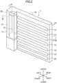
- the terms "upper,” “lower,” “left,” “right,” “front,” and “rear” used in description of the casing (10) refer to directions as viewed in FIG. 2 (directions when the casing (10) is viewed from the front).
- the casing (10) is formed in a rectangular parallelepiped shape having a relatively short depth in the front-rear direction. Specifically, the casing (10) has a fan storing portion (11), suction ports (12), an air passage (13), and blow-out ports (14).
- the fan storing portion (11) stores the blower fan (20).
- the fan storing portion (11) is provided at the left end of the casing (10).
- the fan storing portion (11) is formed in a substantially tubular shape extending in the upper-lower direction.
- the suction ports (12) are formed in the rear surface and left surface of the fan storing portion (11) (indicated by chain double-dashed lines in FIG. 2 ).
- the suction port (12) is formed vertically long. Air in the indoor space (S) is sucked into the blower fan (20) through the suction ports (12).
- the blower fan (20) is a blower mechanism (20) of the present disclosure.
- the blower fan (20) is, for example, a cross-flow fan.
- the blower fan (20) is arranged so as to extend in the upper-lower direction in the fan storing portion (11) (indicated by a broken line in FIG. 2 ).
- the blower fan (20) is arranged at the inflow end of the air passage (13).
- the blower fan (20) delivers air to the air passage (13).
- the air passage (13) is a space through which air passes from the blower fan (20) to the blow-out ports (14). Specifically, the air passage (13) extends in the right-left direction and also extends in the upper-lower direction in the casing (10).
- the blower fan (20) arranged at the left end of the air passage (13) causes air to flow rightward in the air passage (13).
- the right direction is a first direction of the present disclosure.
- the blow-out ports (14) are formed along the air passage (13). Specifically, the blow-out ports (14) are formed in the front surface of the casing (10) (indicated by chain double-dashed lines in FIG. 4 ). The blow-out ports (14) are formed such that a plurality of slit-shaped openings extending in the right-left direction are arranged in the upper-lower direction. The blow-out port (14) is provided with a rectifying member (40).
- the partition (1) has the rectifying members (40).
- the rectifying member (40) is provided at the opening of each blow-out port (14).
- the rectifying member (40) is provided over the entire opening of the blow-out port (14), and makes a uniform flow direction of air blown out through the blow-out port (14).
- the rectifying member (40) has a porous portion (41) formed with a plurality of holes (41a).
- the rectifying member (40) is, for example, a punching metal.
- the porous portion (41) is formed such that the opening area of the hole (41a) gradually decreases from an intermediate position toward both ends of the air passage (13) in the lateral direction (right direction) thereof.
- the maximum opening area of the hole (41a) of the porous portion (41) is about 1.5 times as large as the minimum opening area.
- the partition (1) has the heater (30).
- the heater (30) is, for example, a far infrared heater.
- the heater (30) is a heat supply device (30) of the present disclosure.
- the heater (30) is arranged in a lower portion of the casing (10).
- the heater (30) is arranged so as to extend in the right-left direction.
- the heater (30) is exposed to the small space (ss) in the lower portion of the casing (10).
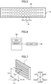
- the partition (1) includes a controller (50).
- the controller (50) includes a CPU that executes a control program, and a memory that stores the control program, data necessary for executing the control program, etc.
- the controller (50) controls the number of rotations of the blower fan (20). By controlling the number of rotations of the blower fan (20), an airflow generated by air blown out through the blow-out ports (14) is adjusted so as to irregularly change within a predetermined range of momentum. Details will be described below.
- the partition (1) of this example blows air toward a first plane (R1) facing the blow-out ports (14).
- the first plane (R1) is a virtual plane (R) of the present disclosure.
- the blower fan (20) is controlled so as to generate, on the first plane (R1), an airflow whose average momentum p per unit area irregularly changes in a range of 0.05 kg/ms 2 or more and 0.75 kg/ms 2 or less.
- the first plane (R1) is a region where a wind velocity is 0.2 m/s or more.
- the first plane (R1) is a plane formed perpendicular to and centered on a center line CL (line extending forward from the center O of the blow-out port (14)).
- the first plane (R1) is a rectangular plane having a width of 0.6 m and a height of 0.5 m about a point O1 on the center line CL at a position apart by 0.3 m from the center O.
- the blower fan (20) is controlled so as to generate, on the first plane (R1), an airflow whose average momentum p per unit area irregularly changes in a range of 0.05 kg/ms 2 or more and 0.75 kg/ms 2 or less when the environment of the indoor space (S) has a room temperature of 20°C and 1 atm (standard atmospheric pressure).
- the air density ⁇ at a temperature of 20°C and a pressure of 1 atm is 0.166 kg/m 3 .
- the airflow whose average momentum p is in the range of 0.05 kg/ms 2 or more and 0.75 kg/ms 2 or less is in a range of 0.2 [m/s] or more and 0.8 [m/s] or less in terms of wind velocity.
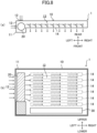
- FIG. 8(a) illustrates the cross section of the partition (1) as viewed from above.
- FIG. 8(b) illustrates the longitudinal section of the partition (1) as viewed from the front. Arrows in FIG. 8 indicate a direction in which air flows.
- blower fan (20) When the blower fan (20) is turned on, air is sucked through the suction ports (12). The sucked air is delivered from the blower fan (20) to the air passage (13). The air in the air passage (13) is blown out through the blow-out ports (14) while flowing toward the tip end (right surface) of the air passage (13). In this manner, the air is blown out through all the openings of the blow-out ports.
- the partition (1) of this embodiment has a blowing function of blowing air into a predetermined space.
- the partition (1) generates, on the virtual plane (R) facing the blow-out ports (14) and having a wind velocity of 0.2 m/s or more, an airflow whose average momentum per unit area is 0.05 kg/ms 2 or more and 0.75 kg/ms 2 or less.
- the partition (1) of this embodiment can improve the efficiency of ventilation of the small space (ss). Consequently, the efficiency of ventilation of the entire indoor space (S) can also be improved.
- the average momentum of the airflow per unit area is set to 0.05 kg/ms 2 or more and 0.75 kg/ms 2 or less, whereby the flow velocity of air blown out through the blow-out port (14) can be reduced.
- the power consumption and the noise can be reduced.
- the partition (1) is portable, the small space (ss) having a desired size can be formed at a desired position. Further, installation work such as construction work is not necessary.
- the momentum of air blown out through the blow-out port (14) is irregularly changed on the virtual plane (R).
- the momentum of air changes irregularly fluctuating wind is generated.
- the comfort of a person in the space partitioned by the partitions (1) can be improved by the fluctuating wind.
- the first plane (R1) (virtual plane (R)) is a plane having a width of 0.6 m and a height of 0.5 m at the position 0.3 m away from the blow-out port (14).
- the partition (1) of this embodiment further includes the rectifying members (40) that makes a uniform flow direction of air blown out through the blow-out port (14).
- the rectifying members (40) With the rectifying members (40), the air blown out through the blow-out port (14) can flow in the same direction regardless of a blow-out position.
- the volume of air blown out through the blow-out port (14) is also made uniform regardless of the blow-out position. Since the vector of the momentum of the blown air is unified in this manner, the small space (ss) can be efficiently ventilated even with a small momentum. Further, it is possible to reduce variation in the volume of air and to reduce impairment of the comfort in the small space (ss).
- the partition (1) of this embodiment further includes the air passage (13) provided in the casing (10).
- the air passage (13) extends in the first direction in which air is delivered from the blower mechanism (20), and is formed such that the tip end of the air passage (13) is closed.
- the blow-out ports (14) are arranged along the air passage (13).
- the rectifying member (40) is provided in the blow-out port (14), and has the porous portion (41) formed with the plurality of holes.
- the porous portion (41) is formed such that the opening area of the hole gradually decreases from the intermediate position toward both ends of the air passage (13) in the first direction thereof.
- the area of the blow-out ports (14) can be increased.
- the momentum p of the airflow blown out through the blow-out ports (14) can be sufficiently ensured even if the flow velocity of the airflow from the blow-out ports (14) is reduced. With this configuration, the comfort in the small space (ss) and the efficiency of ventilation of the small space (ss) can be improved.
- the tip end of the air passage (13) is closed and the porous portion (41) is formed such that the opening area of the hole (41a) gradually decreases from the intermediate position toward both ends in the first direction, the direction and volume of air blown out through the blow-out port (14) can be made uniform.
- the partition (1) of this embodiment further includes the heater (heat supply device) (30) that supplies heat to a position close to the lower end of the casing (10).
- the heater heat supply device
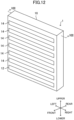
- the opening area of the blow-out ports (14) of the partition (1) of this example is greater than that of the partition (1) of the above-described embodiment.
- the partition (1) of this example sends air toward a second plane (R2) facing the blow-out ports (14).
- the second plane (R2) is a virtual plane (R) of the present disclosure.
- the blower fan (20) is controlled so as to generate, on the second plane (R2), an airflow whose average momentum p per unit area irregularly changes in a range of 0.05 kg/ms 2 or more and 0.75 kg/ms 2 or less.
- the second plane (R2) is a region where a wind velocity is 0.2 m/s or more. Referring to FIG.
- the second plane (R2) is a plane formed perpendicular to and centered on the center line CL.
- the second plane (R2) is a rectangular plane having a width of 1.2 m and a height of 0.5 m about a point O2 on the center line CL at a position apart by 2.0 m from the center O.
- the opening area of the blow-out ports (14) of the partition (1) of this example is greater than that of the partition (1) of the above-described first variation.
- the partition (1) of this example sends air toward a third plane (R3) facing the blow-out ports (14).
- the third plane (R3) is a virtual plane (R) of the present disclosure.
- the blower fan (20) is controlled so as to generate, on the third plane (R3), an airflow whose average momentum p per unit area irregularly changes in a range of 0.05 kg/ms 2 or more and 0.75 kg/ms 2 or less.
- the third plane (R3) is a region where a wind velocity is 0.2 m/s or more. Referring to FIG.
- the third plane (R3) is a plane formed perpendicular to and centered on the center line CL.
- the third plane (R3) is a rectangular plane having a width of 1.8 m and a height of 0.5 m about a point O3 on the center line CL at a position apart by 4.0 m from the center O.
- the partitions (1) of the embodiment, the first variation, and the second variation as described above according to the size of the small space (ss), it is possible to form the small space (ss) having a relatively high ventilation efficiency while maintaining the comfort.
- the casing (10) is formed such that the front surface and the rear surface become closer to each other as approaching the right end.
- the air passage (13) is formed such that a flow path sectional area which is a section perpendicular to the right direction (first direction) gradually decreases in the right direction.
- the partition (1) of this example has no rectifying member (40).
- the flow path sectional area of the air passage (13) gradually decreases in the direction in which air flows from the blower fan (20), so that the flow direction and volume of air blown out through all the blow-out ports (14) can be made uniform.
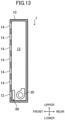
- the suction port (12) of the partition (1) of this example is formed in a lower portion of the front surface of the casing (10).
- the suction port 12 may be formed in the rear surface of the casing 10.
- the suction port (12) is formed so as to extend in the right-left direction of the casing (10).
- the blower fan (20) of the partition (1) of this example is arranged in the lower end of the casing (10).
- the blower fan (20) of this example is, for example, a sirocco fan or a turbo fan. Air is delivered upward in the casing (10) by the blower fan (20).
- the upward direction is a first direction of the present disclosure.
- the air passage (13) is formed in the upper-lower direction. In this manner, the blower fan (20) delivers air sucked through the suction port (12) upward in the air passage (13).
- the partition (1) of this example includes an air purification filter (60).
- the air purification filter (60) is an air purification unit (60) of the present disclosure.
- the air purification filter (60) is arranged at the suction port (12).
- the blow-out ports (14) are formed over the substantially entire front surface of the casing (10), the airflow whose average momentum p per unit area of the virtual plane (R) irregularly changes in the range of 0.05 kg/ms 2 or more and 0.75 kg/ms 2 or less is generated, so that the comfort in the small space (ss) can be improved and the small space (ss) can be efficiently ventilated.
- the air purification filter (60) With the air purification filter (60), the small space (ss) can be supplied with air from which a floating substance such as pollen, house dust, dust, or a microorganism has been removed. As a result, it is possible to suppress an increase in the risk of infection by, e.g., pathogenic bacteria, to alleviate allergic symptoms, and therefore to provide a sense of security to a person in the small space (ss).
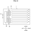
- the heater (30) of the fifth variation is of a heat pump type. Specifically, the heater (30) has an evaporator (31) and a radiator (32). The evaporator (31) and the radiator (32) are connected to a refrigerant circuit including a decompression valve (not shown) and a compressor (not shown). When the refrigerant circuit performs a refrigeration cycle, refrigerant dissipates heat to air in the radiator and absorbs heat from air by evaporating in the evaporator. Arrows illustrated in FIG. 14 indicate the flow of air.
- the evaporator (31) and the radiator (32) are arranged between the blower fan (20) and the inflow end of the air passage (13).
- the evaporator (31) is arranged above the radiator (32).
- air blown out from the blower fan (20) air flowing through an upper portion in the casing (10) is cooled by passing through the evaporator (31) and exchanging heat with refrigerant.
- the cooled air flows through an upper portion of the air passage (13), and is blown out through the blow-out ports (14) arranged in the upper portion of the casing (10).
- air blown out from the blower fan (20) air flowing through a lower portion in the casing (10) is heated, on the other hand, by passing through the radiator (32) and exchanging heat with refrigerant.
- the heated air flows through a lower portion of the air passage (13), and is blown out through the blow-out ports (14) arranged in the lower portion of the casing (10).
- the partition (1) of this example can blow out relatively cool air to an upper portion of the small space (ss) and blow relatively warm air to a lower portion of the small space (ss). This improves the comfort in the small space (ss).
- the partition (1) of this example includes an axial flow fan as the blower fan (20).
- the axial flow fan includes an impeller (20a).
- the impeller (20a) is a so-called propeller fan.
- each blower fan (20) is provided with a fan motor that drives the impeller (20a).
- the impeller (20a) is attached to an output shaft of the fan motor.
- sixteen blower fans (20) are arranged in a matrix, which includes four in the right-left direction and four in the upper-lower direction, in the casing (10).
- the sixteen blower fans (20) face the front surface of the casing (10).
- the blow-out ports (14) are formed at positions corresponding to the sixteen blower fans (20).
- the blow-out ports (14) are arranged in a matrix which includes four in the right-left direction and four in the upper-lower direction.
- the suction port is formed in the rear surface of the casing (10).
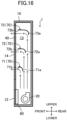
- FIG. 16 is a longitudinal sectional view of the partition (1) according to the seventh variation. As illustrated in FIG. 16 , the suction port (12) of the partition (1) of this example is formed in a lower portion of the front surface of the casing (10).
- the suction port (12) is formed so as to extend in the right-left direction of the casing (10).
- the opening area of the suction port (12) of this example is formed to be greater than the sectional area of the air passage (13) perpendicular to the air flow direction.
- the air passage (13) is formed in the upper-lower direction.
- the upward direction is a first direction of the present disclosure.
- the upper end of the air passage (13) is closed by a top panel of the casing.
- the blower fan (20) of the partition (1) of this example is arranged in the lower end of the casing (10).
- the blower fan (20) of this example is a sirocco fan. Air is delivered upward in the casing (10) by the blower fan (20). In this example, the blower fan (20) delivers air sucked through the suction port (12) upward in the air passage (13).
- the suction port (14) is arranged along the air passage (13).
- the blow-out port (14) is formed above the suction port (12) in the front surface, where the suction port (12) is formed, of the casing (10).
- the opening area of the blow-out port (14) is greater than the opening area of the suction port (12).
- the blow-out port (14) is formed over the substantially entire front surface of the casing (10) except for the suction port (12).
- the blow-out port (14) is provided with the rectifying member (40).
- the rectifying member (40) is formed in a honeycomb shape in which octagonal holes are regularly arranged.
- the air passage (13) is provided with a guide portion (70).
- the guide portion (70) guides air in the air passage (13) to the blow-out port (14) so as to make a uniform wind velocity of air blown out through the blow-out port (14).
- the guide portion (70) has a first flap (71), a second flap (72), and a third flap (73).
- the first flap (71), the second flap (72) and the third flap (73) are arranged in order from below.
- the first flap (71) is arranged at a position higher than the lower end of the blow-out port (14).
- the third flap (73) is arranged at a height position lower than the upper end of the blow-out port (14).
- the first flap (71), the second flap (72), and the third flap (73) are arranged at equal intervals in the upper-lower direction.
- Each flap (71, 72, 73) extends in the right-left direction of the air passage (13). Specifically, each flap (71, 72, 73) extends from one end to the other end of the air passage (13) in the right-left direction.
- each flap (71, 72, 73) is formed in an inverted L-shape in longitudinal section.
- each flap (71, 72, 73) includes a first plate member (71a, 72a, 73a) facing the front surface (back surface) of the casing (10) and a second plate member (71b, 72b, 73b) connected to the upper end of the first plate member (71a, 72a, 73a).
- the second plate member (71b, 72b, 73b) is arranged so as to face the upper surface of the casing (10).
- the first plate member (71a, 72a, 73a) and the second plate member (71b, 72b, 73b) are connected to each other such that the longitudinal section thereof is curved in an arc shape.
- Each flap (71, 72, 73) is arranged such that the front end of the second plate member (71b, 72b, 73b) is at the same distance from the blow-out port (14).
- the first plate members (71a, 72a, 73a) are at different positions in the front-rear direction. Specifically, the first plate member (71a) of the first flap (71) is arranged on the front side with respect to the first plate member (72a) of the second flap (72), and the first plate member (72a) of the second flap (72) is arranged on the front side with respect to the first plate member (73a) of the third flap (73).
- the suction port (12) is provided with the air purification filter (60).
- the air purification filter (60) is provided over the entire region of the suction port (12).
- air passing on the front side of the first plate member (71a) of the first flap (71) is guided by the second plate member (71b) of the first flap (71), and is blown out from the height position of the first flap (71) (specifically, between the lower end of the blow-out port (14) and the height position of the first flap (71)).
- air flowing through the air passage (13) is divided into a plurality of flows by the guide portion (70), and then, is blown out from the entire area of the blow-out port (14) such that the air flow rate is uniform.
- the wind velocity of the air blown out through the blow-out port (14) is made uniform.
- the blow-out port (14) is provided with the rectifying member (40), the air is rectified and blown out through the blow-out port (14).
- the suction port (12) is provided with the air purification filter (60) to purify air flowing into the suction port (12). Since the opening area of the suction port (12) is greater than the sectional area of the air passage (13) perpendicular to the air flow, the air flow resistance of the air flowing through the air passage (13) can be reduced as compared to a case where the air passage (13) is provided with the air purification filter (60). With this configuration, the operating load of the blower fan (20) can be reduced, energy saving and cost saving can be achieved, and the life of the blower fan (20) can be extended.
- the blow-out port (14) is formed over the substantially entire front surface of the casing (10), the airflow whose average momentum p per unit area of the virtual plane (R) is in the range of 0.05 kg/ms 2 or more and 0.75 kg/ms 2 or less is generated, so that the comfort in the small space (ss) can be improved and the small space (ss) can be efficiently ventilated.
- the airflow generated by the blower fan (20) may have a momentum per unit area in a range of 0.05 kgm/s 2 or more and 0.75 kgm/s 2 or less.
- the blower fan (20) is only required to generate the airflow whose average momentum per unit area is in the range of 0.05 kg/ms 2 or more and 0.75 kg/ms 2 or less, and the average momentum does not necessarily change.
- the blower fan (20) may generate an airflow whose average momentum per unit area regularly changes in an average range of 0.05 kg/ms 2 or more and 0.75 kg/ms 2 or less.
- the partition (1) of the above-described embodiment is not necessarily provided with the heater (30). In other variations, the partition (1) may be provided with the heater (30).
- a plurality of partitions (1) may be combined according to the size of the small space (ss).
- a plurality of partitions (1) may be arranged vertically or horizontally adjacent to each other, or a pair of partitions (1) may be arranged so as to face each other such that the blow-out ports (14) face each other.
- blower fans (20) of the embodiment and the second variation described above may be sirocco fans, turbo fans, or propeller fans.
- the partition (1) of the first variation described above may have the rectifying member (40).
- the blower fan (20) of the second variation described above may be a cross-flow fan or a propeller fan.
- the partitions (1) of the embodiment described above and the variations other than the second variation described above may have the air purification units (60).
- the air purification unit (60) is arranged at the suction port (12).
- the air purification unit (60) may have a function of deodorizing or sterilizing sucked air in addition to a function of removing a floating substance etc. contained in the sucked air.
- the air purification unit (60) may have a UV sterilization lamp, a deodorizing filter, a streamer unit, etc.
- the porous portion (41) of the rectifying member (40) is only required to be formed such that the air flow resistance of the hole (41a) in the vicinity of the middle in the right-left direction is smaller than the air flow resistance of the hole (41a) in the vicinity of each end.
- the rectifying member (40) may be cloth. In this case, air is blown out through the weave pattern of the cloth, and therefore, the direction and volume of blown air can be made uniform regardless of the position in the blow-out port (14).
- the rectifying member (40) may be a louver. The direction and volume of blown air can be adjusted by the louver.
- the partition (1) does not necessarily have the sixteen blower fans (20), and may be configured such that sixteen or less blower fans (20) or sixteen or more blower fans (20) are arranged in a matrix. Further, the number of blower fans (20) in the right-left direction and the number of blower fans (20) in the upper-lower direction may not necessarily be the same as each other.
- the air purification filter (60) may be provided in the blow-out port (14). With this configuration, air passing through the air purification filter (60) is rectified. As described above, the air purification filter (60) serves both to purify air in the air passage (13) and to rectify blown air, thereby eliminating the need for providing the rectifying member (40) in the blow-out port (14).
- the present invention is useful for a partition.
Landscapes
- Engineering & Computer Science (AREA)
- Combustion & Propulsion (AREA)
- Mechanical Engineering (AREA)
- General Engineering & Computer Science (AREA)
- Chemical & Material Sciences (AREA)
- Physics & Mathematics (AREA)
- Architecture (AREA)
- Thermal Sciences (AREA)
- Electromagnetism (AREA)
- Civil Engineering (AREA)
- Structural Engineering (AREA)
- Fluid Mechanics (AREA)
- Air-Flow Control Members (AREA)
- Structures Of Non-Positive Displacement Pumps (AREA)
- Ventilation (AREA)
Claims (11)
- Trennwand mit einer Luftblasfunktion zum Blasen von Luft in einen vorbestimmten Bereich, umfassend:ein Gehäuse (10);einen Gebläsemechanismus (20), der in dem Gehäuse (10) angeordnet ist; undeine Ausblasöffnung (14), die in dem Gehäuse (10) ausgebildet ist, undeine Steuerung (50), die eine CPU, die ein Steuerprogramm ausführt, und einen Speicher, der das Steuerprogramm zum Steuern der Anzahl von Umdrehungen des Gebläsemechanismus (20) speichert, enthält,dadurch gekennzeichnet, dass
die Steuerung (50) konfiguriert ist, um einen Luftstromauf einer virtuellen Ebene (R), die der Ausblasöffnung (14) zugewandt ist, zu erzeugen, wobei der Luftstrom eine Windgeschwindigkeit von 0,2 m/s oder mehr aufweist und dessen durchschnittlicher Impuls pro Flächeneinheit in einem Bereich von 0,05 kg/ms2 oder mehr und 0,75 kg/ms2 oder weniger liegt,wobeidie virtuelle Ebene (R) eine Ebene mit einer Breite von 0,6 m und einer Höhe von 0,5 m an einer Position ist, die um 0,3 m von der Ausblasöffnung (14) entfernt ist, oder
wobeidie virtuelle Ebene (R) eine Ebene mit einer Breite von 1,2 m und einer Höhe von 0,5 m an einer Position ist, die um 2,0 m von der Ausblasöffnung (14) entfernt ist, oder
wobeidie virtuelle Ebene (R) eine Ebene mit einer Breite von 1,8 m und einer Höhe von 0,5 m an einer Position ist, die um 4,0 m von der Ausblasöffnung (14) entfernt ist. - Trennwand nach Anspruch 1, wobei
sich ein Impuls von Luft, die durch die Ausblasöffnung (14) ausgeblasen wird, auf der virtuellen Ebene (R) unregelmäßig ändert. - Trennwand nach Anspruch 1, ferner umfassend:einen Luftdurchgang (13), der in dem Gehäuse (10) bereitgestellt ist,
wobeisich der Luftdurchgang (13) in einer ersten Richtung erstreckt, in der Luft von dem Gebläsemechanismus (20) zugeführt wird, und derart ausgebildet ist, dass ein Spitzenende des Luftdurchgangs (13) geschlossen ist, unddie Ausblasöffnung (14) entlang des Luftdurchgangs (13) angeordnet ist. - Trennwand nach Anspruch 3, ferner umfassend:
einen Führungsabschnitt (70), der Luft in dem Luftdurchgang (13) zu der Ausblasöffnung (14) führt, um eine gleichmäßige Windgeschwindigkeit von Luft, die durch die Ausblasöffnung (14) ausgeblasen wird, herzustellen. - Trennwand nach Anspruch 3 oder 4, ferner umfassend:
ein Gleichrichtungselement (40), das eine gleichmäßige Strömungsrichtung von Luft, die durch die Ausblasöffnung (14) ausgeblasen wird, herstellt. - Trennwand nach Anspruch 5, wobeidas Gleichrichtungselement (40) in der Ausblasöffnung (14) vorgesehen ist und einen porösen Abschnitt (41) aufweist, der mit einer Vielzahl von Löchern (41a) ausgebildet ist, undder poröse Abschnitt (41) derart ausgebildet ist, dass eine Öffnungsfläche des Lochs (41a) von einer Zwischenposition zu beiden Enden des Luftdurchgangs (13) in der ersten Richtung allmählich abnimmt.
- Trennwand nach Anspruch 1 oder 2, ferner umfassend:einen Luftdurchgang (13), der in dem Gehäuse (10) bereitgestellt ist,
wobeisich der Luftdurchgang (13) in einer ersten Richtung erstreckt, in der Luft von dem Gebläsemechanismus (20) zugeführt wird, und derart ausgebildet ist, dass ein Spitzenende des Luftdurchgangs (13) geschlossen ist,die Ausblasöffnung (14) entlang des Luftdurchgangs (13) angeordnet ist, undeine Querschnittsfläche des Luftdurchgangs (13) senkrecht zu der ersten Richtung in der ersten Richtung allmählich abnimmt. - Trennwand nach Anspruch 1 oder 2, ferner umfassend:
eine Wärmezufuhrvorrichtung (30), die einer Position nahe einem unteren Ende des Gehäuses (10) Wärme zuführt. - Trennwand nach Anspruch 1 oder 2, ferner umfassend:eine Ansaugöffnung (12), durch die Luft in einem Innenraum (S) angesaugt wird;einen Luftdurchgang (13), der in dem Gehäuse (10) bereitgestellt ist und die Ansaugöffnung (12) und die Ausblasöffnung (14) verbindet; undeine Luftreinigungseinheit (60), die in dem Luftdurchgang (13) angeordnet ist.
- Trennwand nach Anspruch 9, wobei
die Luftreinigungseinheit (60) an der Ausblasöffnung (14) angeordnet ist. - Trennwand nach Anspruch 9, wobei
die Luftreinigungseinheit (60) an der Ansaugöffnung (12) angeordnet ist.
Applications Claiming Priority (2)
| Application Number | Priority Date | Filing Date | Title |
|---|---|---|---|
| JP2021075239 | 2021-04-27 | ||
| PCT/JP2022/018449 WO2022230757A1 (ja) | 2021-04-27 | 2022-04-21 | パーティション |
Publications (3)
| Publication Number | Publication Date |
|---|---|
| EP4306736A1 EP4306736A1 (de) | 2024-01-17 |
| EP4306736A4 EP4306736A4 (de) | 2024-07-17 |
| EP4306736B1 true EP4306736B1 (de) | 2025-05-14 |
Family
ID=83691018
Family Applications (1)
| Application Number | Title | Priority Date | Filing Date |
|---|---|---|---|
| EP22795670.3A Active EP4306736B1 (de) | 2021-04-27 | 2022-04-21 | Trennwand |
Country Status (5)
| Country | Link |
|---|---|
| US (1) | US12270200B2 (de) |
| EP (1) | EP4306736B1 (de) |
| JP (1) | JP7157366B1 (de) |
| CN (1) | CN117178148A (de) |
| WO (1) | WO2022230757A1 (de) |
Families Citing this family (1)
| Publication number | Priority date | Publication date | Assignee | Title |
|---|---|---|---|---|
| KR102802622B1 (ko) * | 2022-10-31 | 2025-05-07 | 주식회사 유니온씨티 | 발열 가능한 파티션을 이용한 난방시스템 |
Family Cites Families (23)
| Publication number | Priority date | Publication date | Assignee | Title |
|---|---|---|---|---|
| US3722580A (en) * | 1971-04-29 | 1973-03-27 | Int Air Conditioning | Modular heating and cooling apparatus |
| US4860642B1 (en) * | 1985-06-11 | 1994-03-29 | Argon Associates L P | Personalized air conditioning and method |
| JPH0761300B2 (ja) * | 1992-08-07 | 1995-07-05 | 日本エアーカーテン株式会社 | 空気清浄機能付つい立て |
| JPH06307707A (ja) * | 1993-04-22 | 1994-11-01 | Matsushita Electric Works Ltd | 間仕切り |
| US6481228B1 (en) * | 2001-08-23 | 2002-11-19 | Industrial Technology Research Institute | Air conditioning module for room partition unit |
| CA2423368A1 (en) * | 2003-03-24 | 2004-09-24 | Jerry Mithuen | Portable air filtration apparatus |
| US7334424B2 (en) * | 2004-10-22 | 2008-02-26 | Winiamando Inc. | Air conditioner having independent cooling and purifying paths |
| JP3949146B2 (ja) * | 2005-07-22 | 2007-07-25 | シャープ株式会社 | 空気調節装置 |
| US9310088B2 (en) * | 2009-07-17 | 2016-04-12 | Technical University Of Denmark | Device and method for reducing spread of microorganisms and airborne health hazardous matter and/or for protection from microorganisms and airborne health hazardous matter |
| JP5313799B2 (ja) * | 2009-07-27 | 2013-10-09 | パナソニック株式会社 | 送風機能付き内装パネル装置 |
| JP2011069563A (ja) * | 2009-09-28 | 2011-04-07 | Panasonic Electric Works Co Ltd | 送風機能付き内装パネル装置 |
| JP5868474B1 (ja) * | 2014-11-07 | 2016-02-24 | 株式会社イースタン | 噴霧装置および噴霧システム |
| CN204461000U (zh) * | 2014-12-24 | 2015-07-08 | 新昌县祥瑞机械设备有限公司 | 一种设有除湿装置的胶板烘干装置 |
| CN106322469A (zh) * | 2015-07-10 | 2017-01-11 | 青岛海尔智能技术研发有限公司 | 油烟机及其调温送风系统 |
| JP6603874B2 (ja) * | 2015-12-22 | 2019-11-13 | パナソニックIpマネジメント株式会社 | 送風装置および送風機能付空気清浄装置 |
| CN105444387B (zh) * | 2015-12-29 | 2018-06-19 | 美的集团武汉制冷设备有限公司 | 出风调节板及空调室内机 |
| CN110121620A (zh) * | 2017-01-06 | 2019-08-13 | 三菱电机株式会社 | 加热烹调器、换气系统及排气方法 |
| JP2019013287A (ja) | 2017-07-04 | 2019-01-31 | 不二ライトメタル株式会社 | 簡易パーテーション |
| CN113464478A (zh) | 2018-02-23 | 2021-10-01 | 大金工业株式会社 | 送风装置 |
| JP6816807B1 (ja) | 2019-09-17 | 2021-01-20 | ダイキン工業株式会社 | 送風機および空調室内機 |
| CN212972744U (zh) * | 2020-04-13 | 2021-04-16 | 宁波方太厨具有限公司 | 一种应用有改进型风道系统的烤箱 |
| US11852375B2 (en) * | 2020-07-10 | 2023-12-26 | 3Flow, Inc. | Ventilation partitions and systems |
| CN112113276B (zh) * | 2020-10-15 | 2022-07-19 | 青岛海尔空调器有限总公司 | 壁挂式空调室内机 |
-
2022
- 2022-04-21 EP EP22795670.3A patent/EP4306736B1/de active Active
- 2022-04-21 WO PCT/JP2022/018449 patent/WO2022230757A1/ja not_active Ceased
- 2022-04-21 CN CN202280029096.7A patent/CN117178148A/zh active Pending
- 2022-04-21 JP JP2022069911A patent/JP7157366B1/ja active Active
-
2023
- 2023-10-25 US US18/383,693 patent/US12270200B2/en active Active
Also Published As
| Publication number | Publication date |
|---|---|
| JP2022169460A (ja) | 2022-11-09 |
| EP4306736A1 (de) | 2024-01-17 |
| EP4306736A4 (de) | 2024-07-17 |
| US12270200B2 (en) | 2025-04-08 |
| JP7157366B1 (ja) | 2022-10-20 |
| CN117178148A (zh) | 2023-12-05 |
| US20240052628A1 (en) | 2024-02-15 |
| WO2022230757A1 (ja) | 2022-11-03 |
Similar Documents
| Publication | Publication Date | Title |
|---|---|---|
| JP2002022198A (ja) | 空気調和機 | |
| CN114484611A (zh) | 壁挂式空调室内机 | |
| JP2021006714A (ja) | 送風装置および空気調和装置 | |
| CN115164280A (zh) | 立式空调室内机 | |
| CN108700312A (zh) | 室内空调系统 | |
| KR20070060875A (ko) | 공기조화기 | |
| US12270200B2 (en) | Partition | |
| JP2005172309A (ja) | 送風装置および室用空調システム | |
| EP0377756B1 (de) | Zimmerkühlvorrichtung mit lokaler strahlung | |
| EP3406979A1 (de) | Klimatisierungssystem | |
| JP6937889B2 (ja) | 空気調和システム | |
| JP2018059675A (ja) | 空気調和機 | |
| US11493231B2 (en) | Indoor unit for air conditioner | |
| JP6292983B2 (ja) | 空調システム | |
| KR20020097465A (ko) | 공기조화기 및 그 토출방법 | |
| EP4012285A1 (de) | Innenraumeinheit einer klimaanlage | |
| JP4729874B2 (ja) | 空気調和機 | |
| JP4418885B2 (ja) | 天井隠蔽型空調機を用いたダクトレス方式による躯体蓄熱空調システム | |
| KR101105765B1 (ko) | 공기조화기 | |
| JP2004263922A (ja) | エアコン室内機 | |
| JP2004324992A (ja) | 冷風換気システム | |
| KR20050104674A (ko) | 에어커튼 기능이 구비되는 공조기 | |
| JP2000337692A (ja) | 空気調和装置 | |
| CN115218278A (zh) | 导风组件及空调器 | |
| JP2007187335A (ja) | 空気調和機 |
Legal Events
| Date | Code | Title | Description |
|---|---|---|---|
| STAA | Information on the status of an ep patent application or granted ep patent |
Free format text: STATUS: THE INTERNATIONAL PUBLICATION HAS BEEN MADE |
|
| PUAI | Public reference made under article 153(3) epc to a published international application that has entered the european phase |
Free format text: ORIGINAL CODE: 0009012 |
|
| STAA | Information on the status of an ep patent application or granted ep patent |
Free format text: STATUS: REQUEST FOR EXAMINATION WAS MADE |
|
| 17P | Request for examination filed |
Effective date: 20231010 |
|
| AK | Designated contracting states |
Kind code of ref document: A1 Designated state(s): AL AT BE BG CH CY CZ DE DK EE ES FI FR GB GR HR HU IE IS IT LI LT LU LV MC MK MT NL NO PL PT RO RS SE SI SK SM TR |
|
| A4 | Supplementary search report drawn up and despatched |
Effective date: 20240614 |
|
| RIC1 | Information provided on ipc code assigned before grant |
Ipc: F24F 13/068 20060101ALI20240610BHEP Ipc: A47G 5/00 20060101ALI20240610BHEP Ipc: F24F 11/77 20180101ALI20240610BHEP Ipc: F24F 11/74 20180101ALI20240610BHEP Ipc: F24F 11/00 20180101ALI20240610BHEP Ipc: F24F 9/00 20060101ALI20240610BHEP Ipc: F24H 3/04 20220101ALI20240610BHEP Ipc: F24F 8/80 20210101ALI20240610BHEP Ipc: F24F 8/108 20210101ALI20240610BHEP Ipc: F24F 7/007 20060101ALI20240610BHEP Ipc: F24F 7/003 20210101ALI20240610BHEP Ipc: E04B 2/74 20060101AFI20240610BHEP |
|
| DAV | Request for validation of the european patent (deleted) | ||
| DAX | Request for extension of the european patent (deleted) | ||
| P01 | Opt-out of the competence of the unified patent court (upc) registered |
Free format text: CASE NUMBER: APP_38385/2024 Effective date: 20240627 |
|
| GRAP | Despatch of communication of intention to grant a patent |
Free format text: ORIGINAL CODE: EPIDOSNIGR1 |
|
| STAA | Information on the status of an ep patent application or granted ep patent |
Free format text: STATUS: GRANT OF PATENT IS INTENDED |
|
| RIC1 | Information provided on ipc code assigned before grant |
Ipc: F24F 13/068 20060101ALI20250121BHEP Ipc: A47G 5/00 20060101ALI20250121BHEP Ipc: F24F 11/77 20180101ALI20250121BHEP Ipc: F24F 11/74 20180101ALI20250121BHEP Ipc: F24F 11/00 20180101ALI20250121BHEP Ipc: F24F 9/00 20060101ALI20250121BHEP Ipc: F24H 3/04 20220101ALI20250121BHEP Ipc: F24F 8/80 20210101ALI20250121BHEP Ipc: F24F 8/108 20210101ALI20250121BHEP Ipc: F24F 7/007 20060101ALI20250121BHEP Ipc: F24F 7/003 20210101ALI20250121BHEP Ipc: E04B 2/74 20060101AFI20250121BHEP |
|
| INTG | Intention to grant announced |
Effective date: 20250206 |
|
| GRAS | Grant fee paid |
Free format text: ORIGINAL CODE: EPIDOSNIGR3 |
|
| GRAA | (expected) grant |
Free format text: ORIGINAL CODE: 0009210 |
|
| STAA | Information on the status of an ep patent application or granted ep patent |
Free format text: STATUS: THE PATENT HAS BEEN GRANTED |
|
| AK | Designated contracting states |
Kind code of ref document: B1 Designated state(s): AL AT BE BG CH CY CZ DE DK EE ES FI FR GB GR HR HU IE IS IT LI LT LU LV MC MK MT NL NO PL PT RO RS SE SI SK SM TR |
|
| REG | Reference to a national code |
Ref country code: GB Ref legal event code: FG4D |
|
| REG | Reference to a national code |
Ref country code: CH Ref legal event code: EP |
|
| REG | Reference to a national code |
Ref country code: DE Ref legal event code: R096 Ref document number: 602022014754 Country of ref document: DE |
|
| REG | Reference to a national code |
Ref country code: IE Ref legal event code: FG4D |
|
| REG | Reference to a national code |
Ref country code: NL Ref legal event code: MP Effective date: 20250514 |
|
| PG25 | Lapsed in a contracting state [announced via postgrant information from national office to epo] |
Ref country code: PT Free format text: LAPSE BECAUSE OF FAILURE TO SUBMIT A TRANSLATION OF THE DESCRIPTION OR TO PAY THE FEE WITHIN THE PRESCRIBED TIME-LIMIT Effective date: 20250915 Ref country code: FI Free format text: LAPSE BECAUSE OF FAILURE TO SUBMIT A TRANSLATION OF THE DESCRIPTION OR TO PAY THE FEE WITHIN THE PRESCRIBED TIME-LIMIT Effective date: 20250514 Ref country code: ES Free format text: LAPSE BECAUSE OF FAILURE TO SUBMIT A TRANSLATION OF THE DESCRIPTION OR TO PAY THE FEE WITHIN THE PRESCRIBED TIME-LIMIT Effective date: 20250514 |
|
| REG | Reference to a national code |
Ref country code: LT Ref legal event code: MG9D |
|
| PG25 | Lapsed in a contracting state [announced via postgrant information from national office to epo] |
Ref country code: NO Free format text: LAPSE BECAUSE OF FAILURE TO SUBMIT A TRANSLATION OF THE DESCRIPTION OR TO PAY THE FEE WITHIN THE PRESCRIBED TIME-LIMIT Effective date: 20250814 Ref country code: GR Free format text: LAPSE BECAUSE OF FAILURE TO SUBMIT A TRANSLATION OF THE DESCRIPTION OR TO PAY THE FEE WITHIN THE PRESCRIBED TIME-LIMIT Effective date: 20250815 |
|
| PG25 | Lapsed in a contracting state [announced via postgrant information from national office to epo] |
Ref country code: NL Free format text: LAPSE BECAUSE OF FAILURE TO SUBMIT A TRANSLATION OF THE DESCRIPTION OR TO PAY THE FEE WITHIN THE PRESCRIBED TIME-LIMIT Effective date: 20250514 Ref country code: PL Free format text: LAPSE BECAUSE OF FAILURE TO SUBMIT A TRANSLATION OF THE DESCRIPTION OR TO PAY THE FEE WITHIN THE PRESCRIBED TIME-LIMIT Effective date: 20250514 |
|
| REG | Reference to a national code |
Ref country code: AT Ref legal event code: MK05 Ref document number: 1794881 Country of ref document: AT Kind code of ref document: T Effective date: 20250514 |
|
| PG25 | Lapsed in a contracting state [announced via postgrant information from national office to epo] |
Ref country code: BG Free format text: LAPSE BECAUSE OF FAILURE TO SUBMIT A TRANSLATION OF THE DESCRIPTION OR TO PAY THE FEE WITHIN THE PRESCRIBED TIME-LIMIT Effective date: 20250514 |
|
| PG25 | Lapsed in a contracting state [announced via postgrant information from national office to epo] |
Ref country code: HR Free format text: LAPSE BECAUSE OF FAILURE TO SUBMIT A TRANSLATION OF THE DESCRIPTION OR TO PAY THE FEE WITHIN THE PRESCRIBED TIME-LIMIT Effective date: 20250514 |
|
| PG25 | Lapsed in a contracting state [announced via postgrant information from national office to epo] |
Ref country code: AT Free format text: LAPSE BECAUSE OF FAILURE TO SUBMIT A TRANSLATION OF THE DESCRIPTION OR TO PAY THE FEE WITHIN THE PRESCRIBED TIME-LIMIT Effective date: 20250514 |
|
| PG25 | Lapsed in a contracting state [announced via postgrant information from national office to epo] |
Ref country code: RS Free format text: LAPSE BECAUSE OF FAILURE TO SUBMIT A TRANSLATION OF THE DESCRIPTION OR TO PAY THE FEE WITHIN THE PRESCRIBED TIME-LIMIT Effective date: 20250814 |
|
| PG25 | Lapsed in a contracting state [announced via postgrant information from national office to epo] |
Ref country code: IS Free format text: LAPSE BECAUSE OF FAILURE TO SUBMIT A TRANSLATION OF THE DESCRIPTION OR TO PAY THE FEE WITHIN THE PRESCRIBED TIME-LIMIT Effective date: 20250914 |
|
| PG25 | Lapsed in a contracting state [announced via postgrant information from national office to epo] |
Ref country code: LV Free format text: LAPSE BECAUSE OF FAILURE TO SUBMIT A TRANSLATION OF THE DESCRIPTION OR TO PAY THE FEE WITHIN THE PRESCRIBED TIME-LIMIT Effective date: 20250514 |
|
| PG25 | Lapsed in a contracting state [announced via postgrant information from national office to epo] |
Ref country code: DK Free format text: LAPSE BECAUSE OF FAILURE TO SUBMIT A TRANSLATION OF THE DESCRIPTION OR TO PAY THE FEE WITHIN THE PRESCRIBED TIME-LIMIT Effective date: 20250514 Ref country code: SM Free format text: LAPSE BECAUSE OF FAILURE TO SUBMIT A TRANSLATION OF THE DESCRIPTION OR TO PAY THE FEE WITHIN THE PRESCRIBED TIME-LIMIT Effective date: 20250514 |
|
| PG25 | Lapsed in a contracting state [announced via postgrant information from national office to epo] |
Ref country code: CZ Free format text: LAPSE BECAUSE OF FAILURE TO SUBMIT A TRANSLATION OF THE DESCRIPTION OR TO PAY THE FEE WITHIN THE PRESCRIBED TIME-LIMIT Effective date: 20250514 |
|
| PG25 | Lapsed in a contracting state [announced via postgrant information from national office to epo] |
Ref country code: EE Free format text: LAPSE BECAUSE OF FAILURE TO SUBMIT A TRANSLATION OF THE DESCRIPTION OR TO PAY THE FEE WITHIN THE PRESCRIBED TIME-LIMIT Effective date: 20250514 |
|
| PG25 | Lapsed in a contracting state [announced via postgrant information from national office to epo] |
Ref country code: SK Free format text: LAPSE BECAUSE OF FAILURE TO SUBMIT A TRANSLATION OF THE DESCRIPTION OR TO PAY THE FEE WITHIN THE PRESCRIBED TIME-LIMIT Effective date: 20250514 |
|
| PG25 | Lapsed in a contracting state [announced via postgrant information from national office to epo] |
Ref country code: IT Free format text: LAPSE BECAUSE OF FAILURE TO SUBMIT A TRANSLATION OF THE DESCRIPTION OR TO PAY THE FEE WITHIN THE PRESCRIBED TIME-LIMIT Effective date: 20250514 |
|
| REG | Reference to a national code |
Ref country code: DE Ref legal event code: R097 Ref document number: 602022014754 Country of ref document: DE |
|
| PLBE | No opposition filed within time limit |
Free format text: ORIGINAL CODE: 0009261 |
|
| STAA | Information on the status of an ep patent application or granted ep patent |
Free format text: STATUS: NO OPPOSITION FILED WITHIN TIME LIMIT |
|
| REG | Reference to a national code |
Ref country code: CH Ref legal event code: L10 Free format text: ST27 STATUS EVENT CODE: U-0-0-L10-L00 (AS PROVIDED BY THE NATIONAL OFFICE) Effective date: 20260325 |
|
| PGFP | Annual fee paid to national office [announced via postgrant information from national office to epo] |
Ref country code: GB Payment date: 20260313 Year of fee payment: 5 |
|
| PGFP | Annual fee paid to national office [announced via postgrant information from national office to epo] |
Ref country code: FR Payment date: 20260309 Year of fee payment: 5 |
|
| 26N | No opposition filed |
Effective date: 20260217 |