EP4302015B1 - Gasbrennervorrichtung mit teilweise vorgemischtem gas - Google Patents
Gasbrennervorrichtung mit teilweise vorgemischtem gas Download PDFInfo
- Publication number
- EP4302015B1 EP4302015B1 EP21707602.5A EP21707602A EP4302015B1 EP 4302015 B1 EP4302015 B1 EP 4302015B1 EP 21707602 A EP21707602 A EP 21707602A EP 4302015 B1 EP4302015 B1 EP 4302015B1
- Authority
- EP
- European Patent Office
- Prior art keywords
- gas
- chamber
- outlet pressure
- valve
- diaphragm
- Prior art date
- Legal status (The legal status is an assumption and is not a legal conclusion. Google has not performed a legal analysis and makes no representation as to the accuracy of the status listed.)
- Active
Links
Images
Classifications
-
- F—MECHANICAL ENGINEERING; LIGHTING; HEATING; WEAPONS; BLASTING
- F23—COMBUSTION APPARATUS; COMBUSTION PROCESSES
- F23N—REGULATING OR CONTROLLING COMBUSTION
- F23N1/00—Regulating fuel supply
- F23N1/02—Regulating fuel supply conjointly with air supply
- F23N1/027—Regulating fuel supply conjointly with air supply using mechanical means
-
- F—MECHANICAL ENGINEERING; LIGHTING; HEATING; WEAPONS; BLASTING
- F23—COMBUSTION APPARATUS; COMBUSTION PROCESSES
- F23N—REGULATING OR CONTROLLING COMBUSTION
- F23N2225/00—Measuring
- F23N2225/04—Measuring pressure
- F23N2225/06—Measuring pressure for determining flow
-
- F—MECHANICAL ENGINEERING; LIGHTING; HEATING; WEAPONS; BLASTING
- F23—COMBUSTION APPARATUS; COMBUSTION PROCESSES
- F23N—REGULATING OR CONTROLLING COMBUSTION
- F23N2235/00—Valves, nozzles or pumps
- F23N2235/12—Fuel valves
- F23N2235/18—Groups of two or more valves
-
- F—MECHANICAL ENGINEERING; LIGHTING; HEATING; WEAPONS; BLASTING
- F23—COMBUSTION APPARATUS; COMBUSTION PROCESSES
- F23N—REGULATING OR CONTROLLING COMBUSTION
- F23N2235/00—Valves, nozzles or pumps
- F23N2235/12—Fuel valves
- F23N2235/20—Membrane valves
-
- F—MECHANICAL ENGINEERING; LIGHTING; HEATING; WEAPONS; BLASTING
- F23—COMBUSTION APPARATUS; COMBUSTION PROCESSES
- F23N—REGULATING OR CONTROLLING COMBUSTION
- F23N2235/00—Valves, nozzles or pumps
- F23N2235/12—Fuel valves
- F23N2235/24—Valve details
Definitions
- the invention relates to a partially-premixed gas burner appliance.
- gas burner appliances there are in principle two different types of gas burner appliances, namely fully-premixed gas burner appliances and partially-premixed gas burner appliances.
- a mixture of gas and air becomes combusted within a combustion chamber of the respective gas burner appliance.
- the present invention relates to a partially-premixed gas burner appliance.
- EP 0 390 964 B2 and US 2009 / 0 197 212 A1 disclose fully-premixed gas burner appliances.
- an air flow provided by a fan is fully premixed with a gas flow provided by a gas modulator before the resulting gas/air mixture is combusted.
- US 2012 / 0 058 439 A1 discloses another fully-premixed gas burner appliance,
- EP 0 103 303 A2 discloses a partially-premixed gas burner appliance comprising a combustion chamber in which gas is combusted.
- a fan provides an air flow to the combustion chamber. The fan is assigned to an exhaust gas outlet port of the combustion chamber. Air is sucked into the combustion chamber when the fan being assigned to the exhaust gas outlet port is running, wherein the air enters into the combustion chamber through an air inlet port.
- An air flow restriction element is assigned to the air inlet port of the combustion chamber.
- a gas modulator provides a gas flow to the combustion chamber, namely to a gas burner rod positioned within the combustion chamber.
- In partially-premixed gas burner appliances only a first portion of the air flow provided by a fan is premixed with the gas flow before combustion takes place.
- a second portion of the air flow provided by the fan is mixed with the gas while the combustion of the gas takes place.
- JP S60 91135 A1 discloses another partially-premixed gas burner appliance.
- the novel partially-premixed gas burner appliance comprises a combustion chamber.
- the novel partially-premixed gas burner appliance further comprises a fan being configured to provide air or an air flow to the combustion chamber.
- the fan is assigned to an air inlet port of the combustion chamber or to an air duct providing the air to the air inlet port.
- the novel partially-premixed gas burner appliance further comprises an air flow restriction element assigned to the air inlet port of the combustion chamber or to the air duct.
- the air flow restriction element is configured to cause a pressure drop so that the air pressure downstream of the air flow restriction element is lower than the air pressure of the air flow provided by the fan upstream of the air flow restriction element.
- the novel partially-premixed gas burner appliance further comprises a gas modulator being configured to provide a gas flow to the combustion chamber.
- a first portion of the air or air flow provided by the fan is premixed with the gas or gas flow before the gas is combusted.
- a second portion of the air or air flow provided by the fan is mixed with the gas while the gas is combusted.
- the gas modulator of the novel partially-premixed gas burner appliance is a pneumatic gas control valve being configured to be used in a fully-premixed gas burner appliance.
- the pneumatic gas control valve has a main gas valve, a safety gas valve, a servo gas valve and a gas outlet pressure regulator. Such a pneumatic gas control valve is configured to be used in a fully-premixed gas burner appliance.
- the gas outlet pressure regulator of the pneumatic gas control valve namely a first chamber of the gas outlet pressure regulator in which a pressure is present that influences the nominal-value of the gas outlet pressure, is connected to the air inlet port of the combustion chamber or to the air duct upstream of the air flow restriction element such that the gas outlet pressure provided by the pneumatic gas control valve depends on the air pressure provided by the fan upstream of the air flow restriction element.
- the present invention proposes to make use of a pneumatic gas control valve being configured to be used in a fully-premixed gas burner appliance within a partially-premixed gas burner appliance.
- the fan is assigned to the air inlet port of the combustion chamber or to an air duct providing the air to the air inlet port.
- the gas outlet pressure regulator of the pneumatic gas control valve namely the first chamber of the same in which the pressure is present that influences the nominal-value of the gas outlet pressure, is connected to the air inlet port of the combustion chamber or to the air duct, namely upstream of the air flow restriction element.
- This makes it possible to provide a 1:1 ratio of the air pressure upstream of the air flow restriction element and the gas outlet pressure of the pneumatic gas control valve without the need of an electronic gas modulator.
- the present invention allows a very simple and reliable 1:1 gas-air control for a partially-premixed gas burner appliance.
- a gas burner rod having at least two segments is positioned within the combustion chamber, wherein the combustion chamber comprises for each segment of the gas burner rod an individual gas inlet port.
- the pneumatic gas control valve provides a gas flow to each of the individual gas inlet ports of the combustion chamber.
- a shut off valve may be assigned to at least one of the individual gas inlet ports to selectively open or close the respective gas inlet port thereby selectively operating the respective segment of the gas burner rod.
- the gas burner rod may not be segmented.
- a gas burner rod not being segmented does not require a shut off valve assigned to the gas inlet port.
- the first chamber of the gas outlet pressure regulator of the pneumatic gas control valve is connected to the air inlet port of the combustion chamber through a pipe or duct. This provides a very simple and reliable way to balance the air pressure drop with the gas pressure drop.
- the gas outlet pressure regulator of the pneumatic gas control valve comprises a diaphragm.
- the first chamber of the gas outlet pressure regulator of the pneumatic gas control valve is positioned on a first side of said diaphragm such that the air pressure being present within the within first chamber acts on the first side of said diaphragm.
- a second chamber of the gas outlet pressure regulator of the pneumatic gas control valve is positioned on a second side of said diaphragm, wherein the second chamber of the gas outlet pressure regulator is connected to a gas outlet chamber of the pneumatic gas control valve such that the gas outlet pressure being present within the within second chamber acts on the second side of said diaphragm.
- the gas outlet pressure regulator further comprises a first spring and a second spring, wherein a spring force provided by the first spring acts on the first side of said diaphragm and a spring force provided by the second spring acts on the second side of said diaphragm.
- the gas outlet pressure regulator of the pneumatic gas control valve further comprises a presetting unit acting on the first spring to adapt the spring force acting on the first side of said diaphragm thereby adapting the nominal-value of the gas outlet pressure. It is possible to provide a very simple and reliable 1:1 gas-air control for a partially-premixed gas burner appliance without the need of an electronic gas modulator.
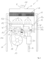
- the present invention relates to a partially-premixed gas burner appliance 10.
- the partially-premixed gas burner appliance 10 comprises a combustion chamber 11 in which gas G is combusted.
- a gas burner rod 12 having at least two segments 12a, 12b is positioned within the combustion chamber 11.
- Gas G is provided to the gas burner rod 12 for combustion.
- the combustion of the gas G takes place under the presence of air A.
- the combustion of the gas G results into flames 13 and exhaust-gas E.
- the gas burner rod 12 may not be segmented in multiple segments.
- a heat exchanger 14 is positioned within the combustion chamber 11.
- the heat exchanger 14 is used to heat e. g. sanitary water or central heating water W for a water consumer.
- the water W to be heated within the heat exchanger 14 is provided by a supply pipe 15 to the heat exchanger 14. Water W which has been heated within the heat exchanger 14 is flowing through a return pipe 16 to the respective water consumer.
- the partially-premixed gas burner appliance 10 comprises a fan 17.
- the fan 17 provides a flow of air A to the combustion chamber 11.
- the fan 17 is assigned to an air inlet port 11A of the combustion chamber 11 or to an air duct 18 providing the air A to the air inlet port 11A.
- the novel partially-premixed gas burner appliance 10 further comprises an air flow restriction element 19 assigned to the air inlet port 11A of the combustion chamber 11 or to the air duct.
- the air flow restriction element 19 causes a pressure drop so that the pressure downstream of the air flow restriction element 19 within the combustion chamber 11 is lower than the pressure of the air flow provided by the fan 17 upstream of the air flow restriction element 19.
- the air flow restriction element 19 can be provided by an orifice plate or by a venturi nozzle.
- the novel partially-premixed gas burner appliance 10 further comprises a gas modulator 20 providing a flow of gas G to the combustion chamber 11, namely through at least one gas inlet port 11G of the combustion chamber 11.
- a gas modulator 20 providing a flow of gas G to the combustion chamber 11, namely through at least one gas inlet port 11G of the combustion chamber 11.
- the combustion chamber 11 may have an individual gas inlet port 11G.
- the combustion chamber 11 may have multiple gas inlet ports 11G.
- a gas flow restriction element 40 is assigned to each of the gas inlet ports 11G. Such a gas flow restriction element 40 causes a pressure drop such that the gas pressure upstream of the gas flow restriction element 40 is greater than the pressure downstream of the gas flow restriction element 40 within the combustion chamber 11.
- the gas flow restriction element 40 can be provided by an orifice plate or by a venturi nozzle.
- a shut off valve 41 is assigned to the gas inlet port 11G providing gas G to the segment 12b of the gas burner rod 12. This makes it possible to selectively open or close the gas inlet port 11G thereby selectively operating the segment 12b of the gas burner rod 12.
- shut off valve 41 the gas inlet port 11G providing gas G to the segment 12a of the gas burner rod 12.
- the exhaust-gas E flows out of the combustion chamber 11 through an exhaust-gas outlet port 11E of the combustion chamber 11.
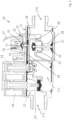
- the gas modulator 20 is provided by a pneumatic gas control valve. Said pneumatic gas control valve 20 is configured to be used in fully-premixed gas burner appliance.
- the pneumatic gas control valve 20 comprises a housing 21 providing an inlet gas chamber 21a, an outlet gas chamber 21b and an intermediate gas chamber 21c coupled between the inlet gas chamber 21a, an outlet gas chamber 21b.
- the pneumatic gas control valve 20 comprises further a main gas valve 22, a safety gas valve 23, a servo gas valve 24 and gas outlet pressure regulator 25.
- the inlet gas chamber 21a and the intermediate gas chamber 21c are fluidically separated from each other.
- the safety gas valve 23 is opened, the intel gas chamber 21a and the intermediate gas chamber 21c are fluidically connected to each other.
- the safety gas valve 12 is opened by an actuator 26 against a closing force provide by a spring 36.
- the safety gas valve 23 is opened, also the servo gas valve 24 becomes opened.
- Safety gas valve 23 and servo gas valve 24 are both opened by the actuator 26.
- the intermediate gas chamber 21c and the outlet gas chamber 21c are fluidically connected to each other.
- the main gas valve 22 comprises a diaphragm 27 and a spring 28.
- the diaphragm 27 separates the outlet gas chamber 21b from a servo pressure chamber 29.
- the servo pressure chamber 29 is fluidically connected to the servo gas valve 24.
- a servo gas pressure being present within the servo gas chamber 29 acts on the second side of the diaphragm 27 of the main gas valve 22 tending to open the main gas valve 22.
- the servo gas chamber 29 is further fluidically connected to the the gas outlet pressure regulator 25 of the pneumatic gas control valve 20 through a pressure relief valve 38.
- the gas outlet pressure regulator 25 of the pneumatic gas control valve 20 comprises a diaphragm 30 and two springs 31, 32.
- the diaphragm 30 of the gas outlet pressure regulator 25 separates a first chamber 33 of the gas outlet pressure regulator 25 from a second chamber 34 of the same.
- the pressure being present within the first chamber 33 of the gas outlet pressure regulator 25 influences the nominal-value of the gas outlet pressure within the outlet gas chamber 21b of the pneumatic gas control valve 20.
- the pressure being present within the first chamber 33 of the gas outlet pressure regulator 25 acts on a first side of the diaphragm 30 of the gas outlet pressure regulator 25. Further on, a spring force provided by the spring 31 acts on a first side of the diaphragm 30.
- the second chamber 34 of the gas outlet pressure regulator 25 is positioned on a second side of said diaphragm 30, wherein the second chamber 34 of the gas outlet pressure regulator 25 is fluidically connected to the gas outlet chamber 11b of the pneumatic gas control valve 20 such that the gas outlet pressure being present within the gas outlet chamber 21b and within the second chamber 34 of the gas outlet pressure regulator 25 acts on the second side of the diaphragm 30 of the gas outlet pressure regulator 25. Further on, a spring force provided by the spring 32 acts on a second side of the diaphragm 30.
- the gas outlet pressure regulator 25 of the pneumatic gas control valve 20 further comprises presetting unit 35 acting on the first spring 31 to adapt the spring force acting on the first side of said diaphragm 30.
- presetting unit 35 acting on the first spring 31 to adapt the spring force acting on the first side of said diaphragm 30.
- the presetting unit 35 can be used to provide an offset or a delta between the pressure on either side of the diaphragm 30 of the gas outlet pressure regulator 25 and as a result an offset or a delta between the generated air pressure and the gas outlet pressure.
- the pressure relief valve 38 through which the servo gas chamber 29 is fluidically connected to the gas outlet pressure regulator 25 of the pneumatic gas control valve 20 is integrated into the diaphragm 30 of the gas outlet pressure regulator 25.
- the gas outlet pressure regulator 25 of the pneumatic gas control valve 20, namely the first chamber 33 of the gas outlet pressure regulator 25 in which the pressure is present that influences the nominal-value of the gas outlet pressure is permanently fluidically connected to the air inlet port 11A of the combustion chamber 11 or to the air duct providing the air A to the air inlet port 11A upstream of the air flow restriction element 18 such that the gas outlet pressure provided by pneumatic gas control valve 20 depends on to the air pressure provided by the fan 17 upstream of the air flow restriction element 18.
- the first chamber 33 of the gas outlet pressure regulator 25 of the pneumatic gas control valve is connected to the air inlet port 11A of the combustion chamber 11 or to the air duct 18 through a pipe or duct 37.
- the pneumatic gas control valve 20 features a positive servo system.
- the main gas valve 22 is closed by the spring 28 in the normal shut down position and can only be opened when pressure within the servo gas chamber 29 is sufficient to overcome the spring force of the spring 28. This ensures the main gas valve 22 will automatically close in the event of power or gas supply failure.
- An element of the pneumatic gas control valve 20 is the gas outlet pressure regulator 25 which comprises the pressure relief valve 38 integrated in the diaphragm 30 which controls the main gas valve 22.
- the pressure relief valve 38 opens relieving some of the working pressure within the servo pressure chamber 29. This reduces the force against the main valve spring 28 allowing the main gas valve 22 to close proportionally.
- the main gas valve 22 limits the gas outlet pressure.
- the gas outlet pressure is continuously maintained by comparing the gas outlet pressure being present in the second chamber 34 of the gas outlet pressure regulator 25 with the pressure being present in the first chamber 33 of the gas outlet pressure regulator 25 and adjusting the position of the main gas valve 22 accordingly.
- the fan 17 is located at the air inlet of the combustion chamber 11.
- the air pressure which is generated by the fan 17 is transferred to first chamber 33 of the gas outlet pressure regulator 25 to generate the outlet gas pressure. This allows to provide a very simple and reliable 1:1 gas-air control for a partially-premixed gas burner appliance.
- the gas outlet pressure and thereby the gas flow provided by the pneumatic gas control valve 20 is a function of air pressure generated by the fan 17.
- An offset or a delta between the pressure on either side of the diaphragm 30 of the gas outlet pressure regulator 25 may be provided by the presetting unit 35.
- the presetting unit 35 At any speed of the fan 17 the pressure drop over air flow restriction 19 equals the pressure drop over the or each gas flow restriction 40. So, the air flow and the gas flow are controlled proportionally.
- presetting unit 35 the gas flow can be influenced to adjust to desired gas and air ratio setting.
Landscapes
- Engineering & Computer Science (AREA)
- Chemical & Material Sciences (AREA)
- Combustion & Propulsion (AREA)
- Mechanical Engineering (AREA)
- General Engineering & Computer Science (AREA)
- Feeding And Controlling Fuel (AREA)
- Regulation And Control Of Combustion (AREA)
Claims (9)
- Teilvormischgasbrennervorrichtung (10), umfassend:eine Brennkammer (11),ein Gebläse (17), das dazu ausgelegt ist, einen Luftstrom zu der Brennkammer (11) bereitzustellen,
wobei das Gebläse (17) einem Lufteinlassanschluss (11A) der Brennkammer (11) oder einem Luftkanal (18) zugeordnet ist, der dazu ausgelegt ist, die Luft zu dem Lufteinlassanschluss (11A) bereitzustellen,ein Luftstrombegrenzungselement (19), das dem Lufteinlassanschluss (11A) der Brennkammer (11) oder dem Luftkanal (18) zugeordnet und dazu ausgelegt ist, einen Druckabfall bereitzustellen, so dass der Druck stromabwärts des Luftstrombegrenzungselements (19) niedriger ist als der Druck stromaufwärts des Luftstrombegrenzungselements (19),einen Gasmodulator (20), der dazu ausgelegt ist, einen Gasstrom zu der Brennkammer (11) bereitzustellen,wobei ein erster Teil der durch das Gebläse (17) bereitgestellten Luft mit dem Gasstrom vorgemischt wird, bevor das Gas verbrannt wird,wobei ein zweiter Teil der durch das Gebläse (17) bereitgestellten Luft mit dem Gas gemischt wird, während das Gas verbrannt wird,wobei der Gasmodulator (20) ein pneumatisches Gassteuerventil ist, das dazu ausgelegt ist, in einer Vollvormischgasbrennervorrichtung verwendet zu werden, wobei das pneumatische Gassteuerventil ein Hauptgasventil (22), ein Sicherheitsgasventil (23), ein Servogasventil (24) und einen Gasauslassdruckregler (25) aufweist,
wobei der Gasauslassdruckregler (25), nämlich eine erste Kammer (33) des Gasauslassdruckreglers (25), in der ein Druck vorhanden ist, der den Nominalwert des Gasauslassdrucks des pneumatischen Gassteuerventils beeinflusst, mit dem Lufteinlassanschluss (11A) oder mit dem Luftkanal (18) stromaufwärts des Luftstrombegrenzungselements (19) verbunden ist, so dass der durch das pneumatische Gassteuerventil bereitgestellte Gasauslassdruck von dem durch das Gebläse (17) stromaufwärts des Luftstrombegrenzungselements (19) bereitgestellten Luftdruck abhängt. - Teilvormischgasbrennervorrichtung nach Anspruch 1, wobei die erste Kammer (33) des Gasauslassdruckreglers (25) des pneumatischen Gassteuerventils über ein Rohr oder einen Kanal (37) mit dem Lufteinlassanschluss (11A) der Brennkammer (11) oder mit dem Luftkanal (18) verbunden ist.
- Teilvormischgasbrennervorrichtung nach Anspruch 1 oder 2, wobeider Gasauslassdruckregler (25) des pneumatischen Gassteuerventils eine Membran (30) umfasst,die erste Kammer (33) des Gasauslassdruckreglers (25) auf einer ersten Seite der Membran (30) positioniert ist, so dass der innerhalb der ersten Kammer (33) vorhandene Druck auf die erste Seite der Membran (30) wirkt,eine zweite Kammer (34) des Gasauslassdruckreglers (25) auf einer zweiten Seite der Membran (30) positioniert ist, wobei die zweite Kammer (34) des Gasauslassdruckreglers (25) mit einer Gasauslasskammer (21b) des pneumatischen Gassteuerventils verbunden ist, so dass der innerhalb der zweiten Kammer (34) vorhandene Gasauslassdruck auf die zweite Seite der Membran (30) wirkt.
- Teilvormischgasbrennervorrichtung nach Anspruch 3, wobeider Gasauslassdruckregler (25) eine erste Feder (31) umfasst, wobei eine durch die erste Feder (31) bereitgestellte Federkraft auf die erste Seite der Membran (30) wirkt,der Gasauslassdruckregler (25) eine zweite Feder (32) umfasst, wobei eine durch die zweite Feder (32) bereitgestellte Federkraft auf die zweite Seite der Membran (30) wirkt,der Gasauslassdruckregler (25) eine Voreinstelleinheit (35) umfasst, die dazu ausgelegt ist, auf die erste Feder (31) zu wirken und die jeweilige auf die erste Seite der Membran (30) wirkende Federkraft anzupassen.
- Teilvormischgasbrennervorrichtung nach Anspruch 4, wobei die Voreinstelleinheit (35) dazu ausgelegt ist, den Nominalwert des Gasauslassdrucks des pneumatischen Gassteuerventils anzupassen.
- Teilvormischgasbrennervorrichtung nach Anspruch 3, 4 oder 5, wobeidas Hauptgasventil (22) des pneumatischen Gassteuerventils eine Membran (27) und eine Feder (28) umfasst,der durch das pneumatische Gassteuerventil bereitgestellte Gasauslassdruck und eine durch die Feder (28) des Hauptgasventils (22) bereitgestellte Federkraft auf eine erste Seite der Membran (27) des Hauptgasventils (22) wirken, was dazu tendiert, das Hauptgasventil (22) zu schließen,eine Servogaskammer (29) auf einer zweiten Seite der Membran (28) des Hauptgasventils (22) positioniert ist, wobei ein innerhalb der Servogaskammer (28) vorhandener Servogasdruck auf die zweite Seite der Membran (27) des Hauptgasventils (22) wirkt, was dazu tendiert, das Hauptgasventil (22) zu öffnen,wobei die Servogaskammer (29) mit dem Servogasventil (24) des pneumatischen Gassteuerventils und mit dem Gasauslassdruckregler (25) des pneumatischen Gassteuerventils verbunden ist.
- Teilvormischgasbrennervorrichtung nach Anspruch 6, wobei die Servogaskammer (29) durch ein in die Membran (30) des Gasauslassdruckreglers (25) integriertes Druckentlastungsventil (38) mit dem Gasauslassdruckregler (25) verbunden ist.
- Teilvormischgasbrennervorrichtung nach einem der Ansprüche 1 bis 7, wobeiein Gasbrennerstab (12) mit mindestens zwei Segmenten (12a, 12b) innerhalb der Brennkammer (11) positioniert ist,die Brennkammer (11) für jedes Segment (12a, 12b) des Gasbrennerstabs (12) mindestens einen einzelnen Gaseinlassanschluss (11G) umfasst,das pneumatische Gassteuerventil einen Gasstrom zu jedem der einzelnen Gaseinlassanschlüsse (11G) der Brennkammer (11) bereitstellt.
- Teilvormischgasbrennervorrichtung nach Anspruch 8, wobei ein Absperrventil (41) mindestens einem der einzelnen Gaseinlassanschlüsse (11G) zugeordnet ist, um den jeweiligen Gaseinlassanschluss (11G) selektiv zu öffnen oder zu schließen, wodurch das jeweilige Segment (12a, 12b) des Gasbrennerstabs (12) selektiv betrieben wird.
Applications Claiming Priority (1)
| Application Number | Priority Date | Filing Date | Title |
|---|---|---|---|
| PCT/CN2021/079048 WO2022183429A1 (en) | 2021-03-04 | 2021-03-04 | Partially-premixed gas burner appliance |
Publications (2)
| Publication Number | Publication Date |
|---|---|
| EP4302015A1 EP4302015A1 (de) | 2024-01-10 |
| EP4302015B1 true EP4302015B1 (de) | 2025-06-04 |
Family
ID=74884771
Family Applications (1)
| Application Number | Title | Priority Date | Filing Date |
|---|---|---|---|
| EP21707602.5A Active EP4302015B1 (de) | 2021-03-04 | 2021-03-04 | Gasbrennervorrichtung mit teilweise vorgemischtem gas |
Country Status (4)
| Country | Link |
|---|---|
| US (1) | US20240142103A1 (de) |
| EP (1) | EP4302015B1 (de) |
| CN (1) | CN116981884A (de) |
| WO (1) | WO2022183429A1 (de) |
Families Citing this family (1)
| Publication number | Priority date | Publication date | Assignee | Title |
|---|---|---|---|---|
| JP2024053871A (ja) * | 2022-10-04 | 2024-04-16 | 株式会社ノーリツ | 燃焼装置およびこれを備えた温水装置 |
Family Cites Families (32)
| Publication number | Priority date | Publication date | Assignee | Title |
|---|---|---|---|---|
| DE2247559A1 (de) * | 1972-09-28 | 1974-04-04 | Junkers & Co | Gas- oder oelbeheiztes geraet, insbesondere wassererhitzer |
| FR2295353A1 (fr) * | 1974-12-16 | 1976-07-16 | Saunier Duval | Systeme regulateur de pression de gaz pour chaudieres a gaz a tirage force |
| US4251025A (en) * | 1979-07-12 | 1981-02-17 | Honeywell Inc. | Furnace control using induced draft blower and exhaust stack flow rate sensing |
| DE3163945D1 (en) * | 1980-03-20 | 1984-07-12 | Honeywell Bv | Regulation apparatus for a gas-fired water or air heater which is controllable by a temperature sensor |
| JPS56151813A (en) * | 1980-04-28 | 1981-11-25 | Hitachi Ltd | Proportional burning method and apparatus therefor |
| US4340355A (en) * | 1980-05-05 | 1982-07-20 | Honeywell Inc. | Furnace control using induced draft blower, exhaust gas flow rate sensing and density compensation |
| US4480988A (en) * | 1982-05-17 | 1984-11-06 | Osaka Gas Company, Limited | Surface combustion type burner with air supply entirely as primary air |
| EP0103303A3 (de) | 1982-09-15 | 1984-06-06 | Joh. Vaillant GmbH u. Co. | Brennstoffbeheizte Wärmequelle |
| JPS6091135A (ja) * | 1983-10-25 | 1985-05-22 | Matsushita Electric Ind Co Ltd | ガス燃焼制御装置 |
| DE3911268A1 (de) | 1989-04-07 | 1990-10-11 | Honeywell Bv | Regeleinrichtung fuer gasbrenner |
| CH680749A5 (de) * | 1990-04-04 | 1992-10-30 | Landis & Gyr Betriebs Ag | |
| DE4317981A1 (de) * | 1993-05-28 | 1994-12-01 | Ranco Inc | Gas-Luft-Verhältnisregelvorrichtung für einen Temperaturregelkreis für Gasverbrauchseinrichtungen |
| DE59304310D1 (de) * | 1993-09-16 | 1996-11-28 | Honeywell Bv | Regeleinrichtung für Gasbrenner |
| DE19639992B4 (de) | 1995-09-23 | 2007-09-13 | Vaillant Gmbh | Verfahren zum Steuern des Gasdurchsatzes |
| DE19821853C1 (de) | 1998-05-15 | 1999-07-29 | Honeywell Bv | Regeleinrichtung für Gasbrenner |
| JP3884653B2 (ja) * | 2002-01-11 | 2007-02-21 | 高木産業株式会社 | 給湯装置 |
| CN1839282A (zh) * | 2003-09-08 | 2006-09-27 | 斯特拉普莱奇萨公开有限公司 | 一种用于控制将燃料气体传送到燃烧器装置的系统 |
| JP4253006B2 (ja) * | 2006-03-27 | 2009-04-08 | リンナイ株式会社 | 循環型給湯装置 |
| JP4234738B2 (ja) * | 2006-07-26 | 2009-03-04 | リンナイ株式会社 | 連結給湯システム |
| JP2009144948A (ja) * | 2007-12-12 | 2009-07-02 | Rinnai Corp | 給湯器 |
| US20090197212A1 (en) | 2008-02-04 | 2009-08-06 | Maxitrol Company | Premix Burner Control System and Method |
| DE102008024843A1 (de) | 2008-05-23 | 2009-11-26 | Honeywell Technologies S.A.R.L. | Gasregelgerät |
| DE102010044762A1 (de) * | 2010-09-08 | 2012-03-08 | Honeywell Technologies S.A.R.L. | Vorrichtung zur Kalibrierung einer Gasbrennerregelung |
| JP5792455B2 (ja) * | 2010-12-02 | 2015-10-14 | パーパス株式会社 | 給湯システム、給湯装置及び給湯制御方法 |
| JP5742553B2 (ja) * | 2011-07-28 | 2015-07-01 | 株式会社ノーリツ | 燃焼装置 |
| JP5806143B2 (ja) * | 2012-02-22 | 2015-11-10 | 株式会社パロマ | 給湯器 |
| US9228759B2 (en) * | 2013-10-07 | 2016-01-05 | Rinnai Corporation | Circulating-type hot-water supply device |
| US9921012B2 (en) * | 2013-11-26 | 2018-03-20 | Noritz Corporation | Water heating apparatus |
| EP2966354B1 (de) * | 2014-07-08 | 2017-11-29 | Honeywell Technologies Sarl | Verfahren zum Betrieb eines Gasbrenners |
| CN208764385U (zh) * | 2018-07-23 | 2019-04-19 | 广州市精鼎电器科技有限公司 | 一种伺服气控燃气比例阀总成 |
| JP7265964B2 (ja) * | 2019-08-26 | 2023-04-27 | リンナイ株式会社 | 給湯器 |
| JP7378323B2 (ja) * | 2020-03-17 | 2023-11-13 | リンナイ株式会社 | ガスマニホールド |
-
2021
- 2021-03-04 EP EP21707602.5A patent/EP4302015B1/de active Active
- 2021-03-04 US US18/548,666 patent/US20240142103A1/en active Pending
- 2021-03-04 WO PCT/CN2021/079048 patent/WO2022183429A1/en not_active Ceased
- 2021-03-04 CN CN202180095188.0A patent/CN116981884A/zh active Pending
Also Published As
| Publication number | Publication date |
|---|---|
| WO2022183429A1 (en) | 2022-09-09 |
| EP4302015A1 (de) | 2024-01-10 |
| US20240142103A1 (en) | 2024-05-02 |
| CN116981884A (zh) | 2023-10-31 |
Similar Documents
| Publication | Publication Date | Title |
|---|---|---|
| US7523762B2 (en) | Modulating gas valves and systems | |
| US5685707A (en) | Integrated burner assembly | |
| US20070154856A1 (en) | Dual fuel boiler with backflow-preventing valve arrangement | |
| CN104114947B (zh) | 用于燃烧设备的燃气空气混合装置 | |
| US7789657B2 (en) | Pressure regulator with bleed orifice | |
| EP4302015B1 (de) | Gasbrennervorrichtung mit teilweise vorgemischtem gas | |
| CN106337965B (zh) | 具有流量限制器的流体控制装置 | |
| US8678345B2 (en) | Variable orifice gas flow modulating valve | |
| ATE371132T1 (de) | Gasregel -und sicherheitsventil | |
| EP2623865B1 (de) | Gasbrenner, Betriebsverfahren davon und Brennersystem für mehrere Gase | |
| KR100521387B1 (ko) | 강제급기식 복합연소장치 | |
| EP4449223B1 (de) | Flüssigkeitsregler mit verbesserter drucksteuerung | |
| EP3617596B1 (de) | Verfahren zum betrieb eines gasbrennergeräts | |
| JP7718183B2 (ja) | ボイラ | |
| US7647776B1 (en) | Fluid flow control system | |
| EP0989366A1 (de) | Ventileinheit zur automatischen Regelung der Brenngasdurchflussmenge | |
| US784073A (en) | Heating system. | |
| KR200237292Y1 (ko) | 비례제어가스버너 | |
| JPH0120523Y2 (de) | ||
| JPH0345005Y2 (de) | ||
| JPH0624620Y2 (ja) | 電磁式比例制御弁装置 | |
| JP2012077964A (ja) | 燃焼装置 | |
| KR100402723B1 (ko) | 비례제어가스버너 | |
| RU2420685C2 (ru) | Устройство для управления подачей горючего газа в горелку | |
| JPH0427444B2 (de) |
Legal Events
| Date | Code | Title | Description |
|---|---|---|---|
| STAA | Information on the status of an ep patent application or granted ep patent |
Free format text: STATUS: UNKNOWN |
|
| STAA | Information on the status of an ep patent application or granted ep patent |
Free format text: STATUS: THE INTERNATIONAL PUBLICATION HAS BEEN MADE |
|
| PUAI | Public reference made under article 153(3) epc to a published international application that has entered the european phase |
Free format text: ORIGINAL CODE: 0009012 |
|
| STAA | Information on the status of an ep patent application or granted ep patent |
Free format text: STATUS: REQUEST FOR EXAMINATION WAS MADE |
|
| 17P | Request for examination filed |
Effective date: 20231002 |
|
| AK | Designated contracting states |
Kind code of ref document: A1 Designated state(s): AL AT BE BG CH CY CZ DE DK EE ES FI FR GB GR HR HU IE IS IT LI LT LU LV MC MK MT NL NO PL PT RO RS SE SI SK SM TR |
|
| DAV | Request for validation of the european patent (deleted) | ||
| DAX | Request for extension of the european patent (deleted) | ||
| GRAP | Despatch of communication of intention to grant a patent |
Free format text: ORIGINAL CODE: EPIDOSNIGR1 |
|
| STAA | Information on the status of an ep patent application or granted ep patent |
Free format text: STATUS: GRANT OF PATENT IS INTENDED |
|
| INTG | Intention to grant announced |
Effective date: 20250117 |
|
| GRAS | Grant fee paid |
Free format text: ORIGINAL CODE: EPIDOSNIGR3 |
|
| GRAA | (expected) grant |
Free format text: ORIGINAL CODE: 0009210 |
|
| STAA | Information on the status of an ep patent application or granted ep patent |
Free format text: STATUS: THE PATENT HAS BEEN GRANTED |
|
| AK | Designated contracting states |
Kind code of ref document: B1 Designated state(s): AL AT BE BG CH CY CZ DE DK EE ES FI FR GB GR HR HU IE IS IT LI LT LU LV MC MK MT NL NO PL PT RO RS SE SI SK SM TR |
|
| REG | Reference to a national code |
Ref country code: GB Ref legal event code: FG4D |
|
| REG | Reference to a national code |
Ref country code: CH Ref legal event code: EP |
|
| REG | Reference to a national code |
Ref country code: DE Ref legal event code: R096 Ref document number: 602021031730 Country of ref document: DE |
|
| REG | Reference to a national code |
Ref country code: IE Ref legal event code: FG4D |
|
| REG | Reference to a national code |
Ref country code: NL Ref legal event code: MP Effective date: 20250604 |
|
| PG25 | Lapsed in a contracting state [announced via postgrant information from national office to epo] |
Ref country code: FI Free format text: LAPSE BECAUSE OF FAILURE TO SUBMIT A TRANSLATION OF THE DESCRIPTION OR TO PAY THE FEE WITHIN THE PRESCRIBED TIME-LIMIT Effective date: 20250604 Ref country code: ES Free format text: LAPSE BECAUSE OF FAILURE TO SUBMIT A TRANSLATION OF THE DESCRIPTION OR TO PAY THE FEE WITHIN THE PRESCRIBED TIME-LIMIT Effective date: 20250604 |
|
| REG | Reference to a national code |
Ref country code: LT Ref legal event code: MG9D |
|
| PG25 | Lapsed in a contracting state [announced via postgrant information from national office to epo] |
Ref country code: NO Free format text: LAPSE BECAUSE OF FAILURE TO SUBMIT A TRANSLATION OF THE DESCRIPTION OR TO PAY THE FEE WITHIN THE PRESCRIBED TIME-LIMIT Effective date: 20250904 Ref country code: GR Free format text: LAPSE BECAUSE OF FAILURE TO SUBMIT A TRANSLATION OF THE DESCRIPTION OR TO PAY THE FEE WITHIN THE PRESCRIBED TIME-LIMIT Effective date: 20250905 |
|
| PG25 | Lapsed in a contracting state [announced via postgrant information from national office to epo] |
Ref country code: PL Free format text: LAPSE BECAUSE OF FAILURE TO SUBMIT A TRANSLATION OF THE DESCRIPTION OR TO PAY THE FEE WITHIN THE PRESCRIBED TIME-LIMIT Effective date: 20250604 |
|
| PG25 | Lapsed in a contracting state [announced via postgrant information from national office to epo] |
Ref country code: BG Free format text: LAPSE BECAUSE OF FAILURE TO SUBMIT A TRANSLATION OF THE DESCRIPTION OR TO PAY THE FEE WITHIN THE PRESCRIBED TIME-LIMIT Effective date: 20250604 |
|
| PG25 | Lapsed in a contracting state [announced via postgrant information from national office to epo] |
Ref country code: HR Free format text: LAPSE BECAUSE OF FAILURE TO SUBMIT A TRANSLATION OF THE DESCRIPTION OR TO PAY THE FEE WITHIN THE PRESCRIBED TIME-LIMIT Effective date: 20250604 |
|
| PG25 | Lapsed in a contracting state [announced via postgrant information from national office to epo] |
Ref country code: RS Free format text: LAPSE BECAUSE OF FAILURE TO SUBMIT A TRANSLATION OF THE DESCRIPTION OR TO PAY THE FEE WITHIN THE PRESCRIBED TIME-LIMIT Effective date: 20250904 |
|
| PG25 | Lapsed in a contracting state [announced via postgrant information from national office to epo] |
Ref country code: LV Free format text: LAPSE BECAUSE OF FAILURE TO SUBMIT A TRANSLATION OF THE DESCRIPTION OR TO PAY THE FEE WITHIN THE PRESCRIBED TIME-LIMIT Effective date: 20250604 |
|
| PG25 | Lapsed in a contracting state [announced via postgrant information from national office to epo] |
Ref country code: NL Free format text: LAPSE BECAUSE OF FAILURE TO SUBMIT A TRANSLATION OF THE DESCRIPTION OR TO PAY THE FEE WITHIN THE PRESCRIBED TIME-LIMIT Effective date: 20250604 |
|
| PG25 | Lapsed in a contracting state [announced via postgrant information from national office to epo] |
Ref country code: PT Free format text: LAPSE BECAUSE OF FAILURE TO SUBMIT A TRANSLATION OF THE DESCRIPTION OR TO PAY THE FEE WITHIN THE PRESCRIBED TIME-LIMIT Effective date: 20251006 |
|
| REG | Reference to a national code |
Ref country code: AT Ref legal event code: MK05 Ref document number: 1800640 Country of ref document: AT Kind code of ref document: T Effective date: 20250604 |
|
| PG25 | Lapsed in a contracting state [announced via postgrant information from national office to epo] |
Ref country code: IS Free format text: LAPSE BECAUSE OF FAILURE TO SUBMIT A TRANSLATION OF THE DESCRIPTION OR TO PAY THE FEE WITHIN THE PRESCRIBED TIME-LIMIT Effective date: 20251004 |
|
| PG25 | Lapsed in a contracting state [announced via postgrant information from national office to epo] |
Ref country code: AT Free format text: LAPSE BECAUSE OF FAILURE TO SUBMIT A TRANSLATION OF THE DESCRIPTION OR TO PAY THE FEE WITHIN THE PRESCRIBED TIME-LIMIT Effective date: 20250604 Ref country code: SM Free format text: LAPSE BECAUSE OF FAILURE TO SUBMIT A TRANSLATION OF THE DESCRIPTION OR TO PAY THE FEE WITHIN THE PRESCRIBED TIME-LIMIT Effective date: 20250604 |
|
| PG25 | Lapsed in a contracting state [announced via postgrant information from national office to epo] |
Ref country code: CZ Free format text: LAPSE BECAUSE OF FAILURE TO SUBMIT A TRANSLATION OF THE DESCRIPTION OR TO PAY THE FEE WITHIN THE PRESCRIBED TIME-LIMIT Effective date: 20250604 |
|
| PG25 | Lapsed in a contracting state [announced via postgrant information from national office to epo] |
Ref country code: EE Free format text: LAPSE BECAUSE OF FAILURE TO SUBMIT A TRANSLATION OF THE DESCRIPTION OR TO PAY THE FEE WITHIN THE PRESCRIBED TIME-LIMIT Effective date: 20250604 |
|
| PG25 | Lapsed in a contracting state [announced via postgrant information from national office to epo] |
Ref country code: SK Free format text: LAPSE BECAUSE OF FAILURE TO SUBMIT A TRANSLATION OF THE DESCRIPTION OR TO PAY THE FEE WITHIN THE PRESCRIBED TIME-LIMIT Effective date: 20250604 |
|
| PG25 | Lapsed in a contracting state [announced via postgrant information from national office to epo] |
Ref country code: IT Free format text: LAPSE BECAUSE OF FAILURE TO SUBMIT A TRANSLATION OF THE DESCRIPTION OR TO PAY THE FEE WITHIN THE PRESCRIBED TIME-LIMIT Effective date: 20250604 |