EP4298698B1 - Hochvoltsteckverbinderanordnung - Google Patents
Hochvoltsteckverbinderanordnung Download PDFInfo
- Publication number
- EP4298698B1 EP4298698B1 EP22711917.9A EP22711917A EP4298698B1 EP 4298698 B1 EP4298698 B1 EP 4298698B1 EP 22711917 A EP22711917 A EP 22711917A EP 4298698 B1 EP4298698 B1 EP 4298698B1
- Authority
- EP
- European Patent Office
- Prior art keywords
- connector
- securing element
- plug
- pins
- connectors
- Prior art date
- Legal status (The legal status is an assumption and is not a legal conclusion. Google has not performed a legal analysis and makes no representation as to the accuracy of the status listed.)
- Active
Links
Images

Classifications
-
- H—ELECTRICITY
- H01—ELECTRIC ELEMENTS
- H01R—ELECTRICALLY-CONDUCTIVE CONNECTIONS; STRUCTURAL ASSOCIATIONS OF A PLURALITY OF MUTUALLY-INSULATED ELECTRICAL CONNECTING ELEMENTS; COUPLING DEVICES; CURRENT COLLECTORS
- H01R13/00—Details of coupling devices of the kinds covered by groups H01R12/70 or H01R24/00 - H01R33/00
- H01R13/62—Means for facilitating engagement or disengagement of coupling parts or for holding them in engagement
- H01R13/627—Snap or like fastening
- H01R13/6271—Latching means integral with the housing
- H01R13/6273—Latching means integral with the housing comprising two latching arms
-
- H—ELECTRICITY
- H01—ELECTRIC ELEMENTS
- H01R—ELECTRICALLY-CONDUCTIVE CONNECTIONS; STRUCTURAL ASSOCIATIONS OF A PLURALITY OF MUTUALLY-INSULATED ELECTRICAL CONNECTING ELEMENTS; COUPLING DEVICES; CURRENT COLLECTORS
- H01R13/00—Details of coupling devices of the kinds covered by groups H01R12/70 or H01R24/00 - H01R33/00
- H01R13/46—Bases; Cases
- H01R13/53—Bases or cases for heavy duty; Bases or cases for high voltage with means for preventing corona or arcing
-
- H—ELECTRICITY
- H01—ELECTRIC ELEMENTS
- H01R—ELECTRICALLY-CONDUCTIVE CONNECTIONS; STRUCTURAL ASSOCIATIONS OF A PLURALITY OF MUTUALLY-INSULATED ELECTRICAL CONNECTING ELEMENTS; COUPLING DEVICES; CURRENT COLLECTORS
- H01R13/00—Details of coupling devices of the kinds covered by groups H01R12/70 or H01R24/00 - H01R33/00
- H01R13/46—Bases; Cases
- H01R13/533—Bases, cases made for use in extreme conditions, e.g. high temperature, radiation, vibration, corrosive environment, pressure
-
- H—ELECTRICITY
- H01—ELECTRIC ELEMENTS
- H01R—ELECTRICALLY-CONDUCTIVE CONNECTIONS; STRUCTURAL ASSOCIATIONS OF A PLURALITY OF MUTUALLY-INSULATED ELECTRICAL CONNECTING ELEMENTS; COUPLING DEVICES; CURRENT COLLECTORS
- H01R13/00—Details of coupling devices of the kinds covered by groups H01R12/70 or H01R24/00 - H01R33/00
- H01R13/62—Means for facilitating engagement or disengagement of coupling parts or for holding them in engagement
- H01R13/639—Additional means for holding or locking coupling parts together, after engagement, e.g. separate keylock, retainer strap
-
- H—ELECTRICITY
- H01—ELECTRIC ELEMENTS
- H01R—ELECTRICALLY-CONDUCTIVE CONNECTIONS; STRUCTURAL ASSOCIATIONS OF A PLURALITY OF MUTUALLY-INSULATED ELECTRICAL CONNECTING ELEMENTS; COUPLING DEVICES; CURRENT COLLECTORS
- H01R13/00—Details of coupling devices of the kinds covered by groups H01R12/70 or H01R24/00 - H01R33/00
- H01R13/64—Means for preventing incorrect coupling
- H01R13/641—Means for preventing incorrect coupling by indicating incorrect coupling; by indicating correct or full engagement
-
- H—ELECTRICITY
- H01—ELECTRIC ELEMENTS
- H01R—ELECTRICALLY-CONDUCTIVE CONNECTIONS; STRUCTURAL ASSOCIATIONS OF A PLURALITY OF MUTUALLY-INSULATED ELECTRICAL CONNECTING ELEMENTS; COUPLING DEVICES; CURRENT COLLECTORS
- H01R2201/00—Connectors or connections adapted for particular applications
- H01R2201/26—Connectors or connections adapted for particular applications for vehicles
Definitions
- the invention relates to a high-voltage connector arrangement with a stationary first connector with a first connector housing, with a movably arranged second connector with a second connector housing, wherein the first and the second connector have plug contact elements that are complementary to one another and can be connected to one another, and wherein the second connector has connecting lines connected to its plug contact elements, the outlet direction of which runs perpendicular to the connection direction of the two connectors, and wherein the second connector has a position securing element that can be moved perpendicular to the connection direction and that mechanically locks the two connectors together when the connectors are joined together in a sliding position.
- Such high-voltage connector arrangements are used, for example, in electric vehicles to connect the traction battery.
- a second connector has single-core high-current cables that have a relatively high cable cross-section in accordance with their intended use and are therefore relatively rigid and have a fairly high weight over their length. This is particularly problematic in the case of a connector arrangement designed as an angle connector, since the weight of the high-current cables and their leverage exerts a fairly large force on the interconnected connector housings, which leads to the connected plug contact elements jamming if these forces are not absorbed in a suitable manner.
- a generic high-voltage connector arrangement is known from the German published patent application DE 10 2018 009 478 A1 known.
- one of the two connectors has a rotary lever on which a position securing element is located.
- the rotary lever When the rotary lever is turned, it brings the two connectors together and also actuates a slider, which, when moved, causes an additional positive locking of the two connectors.
- the mechanism required for this is, however, relatively complex and also requires a connector with a rotary lever.
- the task was to create a generic high-voltage connector arrangement in a simple and cost-effective manner in which the aforementioned problems are eliminated or minimized.
- the position securing element has at least two pairs of pins, the longitudinal axes of which are aligned in the direction of displacement of the position securing element and which are arranged in pairs one behind the other with respect to the direction of displacement of the position securing element, and in that in the sliding position locking the connectors, each of the pins of the position securing element engages in a respective recess on the first connector and in a respective recess on the second connector. Pins are thus provided which can be applied between the first and the second connector housing and which ensure the mechanical Additionally lock and stabilize the connection between these connector housings. In order to avoid the need for additional components for the pinning function, this function is implemented using the position securing element. For this purpose, appropriate geometries are provided on the position securing element and on the connector housings.
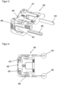
- the Figures 1 and 2 show a high-voltage connector arrangement consisting of two connectors 10, 20, which can be used in an electric vehicle, for example.
- the first connector 10 is connected in a fixed position to a mounting surface 50, which can be part of the body of the electric vehicle, for example.
- the second connector 20 forms a movably arranged connector with several connection lines 30, which can be separated from the first connector 10 and thus from the electric vehicle.
- the first connector 10 includes a first connector housing 11, while the second connector 20 includes a second connector housing 21.
- the first connector 10 has electrical connections 17 which are guided through the mounting surface 50 and whose outlet direction on the first connector housing 11 runs perpendicularly to its mounting surface 50 downwards, and thus at a right angle to the outlet direction of the connection lines 30 of the second connector housing 21.
- the connector arrangement shown here is thus designed as an angle connector arrangement.
- the two connectors 10, 20 have internally complementary pin and socket-like plug contact elements, which can be designed as flat or round plugs.
- Figures 1 and 2 show the first and second connectors 10, 20 in the already plugged-together state, in which the mutually complementary plug contact elements of the first and second connectors 10, 20 - not recognizable as individual parts here - are already connected to one another.
- Position assurance elements 40 are generally known and are often also referred to as CPA elements ("Connector Position Assurance”).
- the position securing element 40 can be moved between two locking positions, which are defined by locking springs 42 on the position securing element 40, which can latch onto the second connector 20.
- High-voltage connector arrangements for electrically powered vehicles generally carry relatively high currents as well as relatively high voltages.
- the connecting cables 30, which are connected to the movably arranged second connector 20 have a relatively large conductor cross-section and a comparatively thick insulating sheath. This in turn means that the connecting cables 30 are quite heavy and, particularly in the case of the angled connector design described here, exert a considerable leverage effect on the interconnected connectors.
- the Figure 3 shows the position securing element 40 as a box-like component which is open to a front and a lower side is designed.
- the position securing element 40 has an upper side 47, the inner surface of which rests displaceably on the second connector 20 in the assembled state.
- Two side parts 48 connected in one piece with the upper side 47 each have a molded-in detent spring 42 which can lock into the first connector housing 11 in at least two sliding positions of the position securing element 40.
- the position securing element 40 has two pins 44, 46 connected to the side parts 48, which are located on the second connector 20 (see Figure 2 ) extend parallel to each other in the outgoing direction of the connecting cable 30. These pins 44, 46 are also referred to below as front pins 44, 46.
- two pins 43, 45 are also connected to the rear side 49 of the position securing element 40, which are referred to below as rear pins 43, 45 for differentiation.
- the two rear pins 43, 45 which are each shorter than the two front pins 44, 46, are designed here as one-piece moldings on the rear side 49 of the position securing element 40, while the front pins 44, 46 are molded onto the side parts 48 of the position securing element 40.
- the front pins 44, 46 can advantageously be designed as metal pins.
- the position securing element 40 has at least two pairs of pins 43, 44; 45, 46, the longitudinal axes of which are aligned in the direction of displacement of the position securing element 40. and which are arranged in pairs one behind the other with respect to the direction of displacement of the position securing element 40.
- a rear pin 43, 45 and a front pin 44, 46 are regarded together as a pin pair.
- the front and rear pins 43, 44 and 45, 46 which belong together in pairs, are arranged one behind the other in the direction of displacement of the position securing element 40 and are also aligned parallel to one another, which, however, as the Figure 4 shows, does not necessarily require an aligned arrangement.
- a double pair of pins 43, 44; 45, 46, as shown here, is particularly advantageous because it allows mechanical stabilization to be achieved symmetrically on both long sides of the two connector housings 11, 21. However, it is also possible to provide a larger number of such pin pairs 43, 44 or 45, 46.
- the position securing element 40 on the second connector 20 can be brought into at least two sliding positions, which in the Figures 1 and 2 are shown.
- the position securing element 40 is in a pre-locking position relative to the connector housings 11, 21, while in the Figure 2 has reached a final locking position.
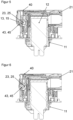
- FIGS. 5 and 6 each show a vertical section along one of the rear pins 43, 45.
- a plug contact element 12 of the first connector 10 which belongs to the first connector 10 and is designed as a flat contact, can also be seen.
- the rear pins 43, 45 formed on the position securing element 40 are located directly in front of a recess 13, 15 in the wall of the first connector housing 11. Immediately behind them and in alignment with the recesses 13, 15, there is a recess 23, 25 in a wall of the second connector housing 21.
- the cross-sectional shape and cross-sectional size of the pins 43, 45 and the recesses 13, 15, 23, 25 are adapted to one another, so that the pins 43, 45 after a displacement of the position securing element 40 in the final locking position ( Figure 6 ) engage in the recesses 13, 15, 23, 25 with little play.
- the position securing element 40 thus locks the first and the second connector housing 11, 21 with both its front and its rear pins 43, 44, 45, 46 at two mutually opposite locations of the peripheral region of the first connector housing 11, both of which lie along the outgoing direction of the connecting lines 30.
- the position securing element 40 arranged on the second connector housing 21 thus creates a stabilizing multiple locking between the two connector housings 11, 21 without increasing the assembly effort when connecting or disconnecting the connectors 10, 20.
Landscapes
- Details Of Connecting Devices For Male And Female Coupling (AREA)
Description
- Die Erfindung betrifft eine Hochvoltsteckverbinderanordnung mit einem ortsfest angeordneten ersten Steckverbinder mit einem ersten Steckverbindergehäuse, mit einem beweglich angeordneten zweiten Steckverbinder mit einem zweiten Steckverbindergehäuse, wobei der erste und der zweite Steckverbinder zueinander komplementäre und miteinander verbindbare Steckkontaktelemente aufweisen, und wobei der zweite Steckverbinder mit seinen Steckkontaktelementen verbundene Anschlussleitungen aufweist, deren Abgangsrichtung senkrecht zur Verbindungsrichtung der beiden Steckverbinder verläuft, und wobei der zweite Steckverbinder ein senkrecht zur Verbindungsrichtung verschiebbares Positionssicherungselement aufweist, das bei zusammengefügten Steckverbindern in einer Schiebeposition die beiden Steckverbinder mechanisch miteinander arretiert.
- Derartige Hochvoltsteckverbinderanordnungen werden beispielsweise in Elektrofahrzeugen zum Anschluss der Traktionsbatterie vorgesehen. Dabei weist ein zweiter Steckverbinder einadrige Hochstromleitungen auf, die entsprechend ihrem Anwendungszweck einen relativ hohen Leitungsquerschnitt aufweisen, und daher relativ starr sind und über ihre Länge ein recht hohes Eigengewicht aufweisen. Besonders bei einer als Winkelsteckverbinder ausgeführten Steckverbinderanordnung ist dieses problematisch, da das Eigengewicht der Hochstromleitungen und deren Hebelwirkung eine recht große Kraft auf die miteinander verbundenen Steckverbindergehäuse ausübt, die zu einem Verkanten der verbundenen Steckkontaktelemente führt, wenn diese Kräfte nicht auf geeignete Weise abgefangen werden.
- Zudem reagieren derartige Hochvoltsteckverbinderanordnungen besonders empfindlich auf Vibrationsbelastungen, wie sie in Kraftfahrzeugen regelmäßig auftreten. Hierbei entstehen Relativbewegungen zwischen den miteinander verbundenen Steckverbindern, welche zu einem erhöhten Reibverschleiß an den elektrischen Steckkontaktelementen führen.
- Eine gattungsgemäße Hochvoltsteckverbinderanordnung ist aus der deutschen Offenlegungsschrift
DE 10 2018 009 478 A1 bekannt. Bei dieser Anordnung weist einer der beiden Steckverbinder einen Drehhebel auf, an dem sich ein Positionssicherungselement befindet. Beim Umlegen des Drehhebels führt dieser die beiden Steckverbinder zusammen und betätigt zudem einen Schieber, der durch seine Verschiebung eine zusätzliche formschlüssige Arretierung der beiden Steckverbinder bewirkt. Der hierzu erforderliche Mechanismus ist allerdings relativ komplex und setzt zudem einen Steckverbinder mit einem Drehhebel voraus. - Ferner ist eine gattungsgemäße Hochvoltsteckverbinderanordnung aus
CN 112 038 837 A bekannt. - Es stellte sich die Aufgabe, auf eine einfache und kostengünstige Weise eine gattungsgemäße Hochvoltsteckverbinderanordnung zu schaffen, bei der die vorgenannten Probleme beseitigt oder minimiert sind.
- Diese Aufgabe wird erfindungsgemäß dadurch gelöst, dass das Positionssicherungselement wenigstens zwei Paare von Stiften aufweist, deren Längsachsen in der Verschieberichtung des Positionssicherungselements ausgerichtet sind, und die hinsichtlich der Verschieberichtung des Positionssicherungselements paarweise hintereinander angeordnet sind, und dass in der die Steckverbinder arretierenden Schiebeposition jeder der Stifte des Positionssicherungselements in jeweils eine Ausnehmung am ersten Steckverbinder und in jeweils eine Ausnehmung am zweiten Steckverbinder eingreift. Vorgesehen sind somit zwischen dem ersten und dem zweiten Steckverbindergehäuse applizierbare Stifte, welche die mechanische Verbindung zwischen diesen Steckverbindergehäusen zusätzlich verriegeln und stabilisieren. Um keine zusätzlichen Bauteile für die Verstiftungsfunktion zu benötigen, wird diese Funktion mittels des Positionssicherungselements realisiert. Dazu werden entsprechende Geometrien an dem Positionssicherungselement, sowie an den Steckverbindergehäusen vorgesehen.
- Vorteilhafte Ausgestaltungen und Weiterbildungen gehen aus dem abhängigen Anspruch sowie der nachfolgenden Beschreibung eines Ausführungsbeispiels der Erfindung anhand der Figuren hervor. Es zeigen die
- Figur 1
- eine Hochvoltsteckverbinderanordnung mit einem Positionssicherungselement in einer Vorraststellung,
- Figur 2
- eine Hochvoltsteckverbinderanordnung mit einem Positionssicherungselement in einer Endraststellung,
- Figur 3
- ein Positionssicherungselement in einer isometrischen Ansicht,
- Figur 4
- das Positionssicherungselement in einer Ansicht von oben,
- Figur 5
- eine erste Schnittansicht der Hochvoltsteckverbinderanordnung mit dem Positionssicherungselement in der Vorraststellung,
- Figur 6
- eine Schnittansicht gemäß der
Figur 5 mit dem Positionssicherungselement in der Endraststellung, - Figur 7
- eine zweite Schnittansicht der Hochvoltsteckverbinderanordnung mit dem Positionssicherungselement in der Vorraststellung,
- Figur 8
- eine Schnittansicht gemäß der
Figur 7 mit dem Positionssicherungselement in der Endraststellung. - Die
Figuren 1 und 2 zeigen eine aus zwei Steckverbindern 10, 20 bestehende Hochvoltsteckverbinderanordnung, die etwa in einem Elektrofahrzeug eingesetzt werden kann. Dabei ist der erste Steckverbinder 10 ortsfest mit einer Montagefläche 50 verbunden, die beispielsweise ein Teil der Karosserie des Elektrofahrzeugs sein kann. Der zweite Steckverbinder 20 bildet einen beweglich angeordneten Verbinder mit mehreren Anschlussleitungen 30 aus, der von dem ersten Steckverbinder 10 und damit von dem Elektrofahrzeug getrennt werden kann. - Bestandteil des ersten Steckverbinders 10 ist ein erstes Steckverbindergehäuse 11, während zum zweiten Steckverbinder 20 ein zweites Steckverbindergehäuse 21 gehört.
- Der erste Steckverbinder 10 weist elektrische Anschlüsse 17 auf, die durch die Montagefläche 50 hindurchgeführt sind und deren Abgangsrichtung am ersten Steckverbindergehäuse 11 senkrecht zu dessen Montagefläche 50 nach unten, und damit im rechten Winkel zur Abgangsrichtung der Anschlussleitungen 30 des zweiten Steckverbindergehäuses 21 verläuft. Die hier dargestellte Steckverbinderanordnung ist somit als Winkelsteckverbinderanordnung ausgeführt.
- Die beiden Steckverbinder 10, 20 weisen intern zueinander komplementäre stift- und buchsenartige Steckkontaktelemente auf, die als Flach- oder Rundstecker ausgeführt sein können. Die
Figuren 1 und 2 zeigen den ersten und zweiten Steckverbinder 10, 20 im bereits zusammensteckten Zustand, in dem die zueinander komplementären - hier nicht als Einzelteile erkennbaren - Steckkontaktelemente des ersten und zweiten Steckverbinders 10, 20 schon miteinander verbunden sind. - Bei dem in der
Figur 1 dargestellten Montagezustand sind die beiden zusammengefügten Steckverbinder 10, 20 noch nicht hinreichend gegen ein Lösen der Steckverbindung gesichert, sondern lediglich über einen am zweiten Steckverbinder 20 befindlichen, in der Zeichnung nicht erkennbaren, Rasthaken, der die Endrastposition definiert, befestigt. Um eine robuste Sicherung zu ermöglichen, ist am zweiten Steckverbinder 20 ein Positionssicherungselement 40 verschiebbar angeordnet, welches in einer von wenigstens zwei möglichen Schiebepositionen eine formschlüssige - Verbindung zum ersten Steckverbinder 10 herstellt. Positionssicherungselemente 40 sind grundsätzlich bekannt und werden häufig auch als CPA-Elemente ("Connector Position Assurance") bezeichnet.
- Vorzugsweise kann das Positionssicherungselement 40 zwischen zwei Raststellungen bewegt werden, welche durch Rastfedern 42 am Positionssicherungselement 40 definiert werden, die am zweiten Steckverbinder 20 einrasten können.
- Hochvoltsteckverbinderanordnungen für elektrisch angetriebene Fahrzeuge führen im Allgemeinen neben relativ hohen Spannungen auch relativ hohe Ströme. Um diesen Umständen gerecht zu werden, weisen die Anschlussleitungen 30, die mit dem beweglich angeordneten zweiten Steckverbinder 20 verbunden sind, einen relativ großen Leiterquerschnitt und eine vergleichsweise dicke Isolierumhüllung auf. Dieses wiederum bewirkt, dass die Anschlussleitungen 30 recht schwer sind und, besonders bei der hier beschriebenen Winkelsteckerausführung eine beachtliche Hebelwirkung auf die miteinander verbundenen Steckverbinder ausüben.
- Zudem führen die in einem Kraftfahrzeug auftretenden Vibrationseinwirkungen zu erheblichen Reibbelastungen der elektrischen Steckkontaktelemente der Steckverbinder 10, 20, sowie auch der Kunststoffteile der Steckverbindergehäuse 11, 21.
- Um diese Belastungen zu minimieren, ist es vorteilhaft, die beiden Steckverbindergehäuse 11, 21 möglichst stabil miteinander zu verbinden. Dieses wird insbesondere durch eine spezielle Ausgestaltung des Positionssicherungselements 40 erreicht, welches in den
Figuren 3 und 4 als Einzelteil dargestellt ist. - Die
Figur 3 zeigt das Positionssicherungselement 40 als ein kastenartiges Bauteil, welches zu einer vorderen und einer unteren Seite hin offen ausgebildet ist. Das Positionssicherungselement 40 besitzt eine Oberseite 47, dessen Innenfläche im montierten Zustand auf dem zweiten Steckverbinder 20 verschiebbar aufliegt. Zwei mit der Oberseite 47 einstückig verbundene Seitenteile 48 weisen jeweils eine eingeformte Rastfeder 42 auf, welche in wenigstens zwei Schiebepositionen des Positionssicherungselements 40 mit dem ersten Steckverbindergehäuse 11 verrasten können. - Eine mit der Oberseite 47 und den Seitenteilen 48 verbundene Rückseite 49 begrenzt eine mögliche Verschiebung des Positionssicherungselements 40 in der Abgangsrichtung der Anschlussleitung 30.
- Das Positionssicherungselement 40 weist zwei mit den Seitenteilen 48 verbundene Stifte 44, 46 auf, die sich am zweiten Steckverbinder 20 (siehe
Figur 2 ) parallel zueinander in der Abgangsrichtung der Anschlussleitung 30 erstrecken. Diese Stifte 44, 46 werden nachfolgend auch als vordere Stifte 44, 46 bezeichnet. - Wie die
Figur 4 zeigt, sind auch mit der Rückseite 49 des Positionssicherungselements 40 zwei Stifte 43, 45 verbunden, die zur Unterscheidung nachfolgend als hintere Stifte 43, 45 benannt werden. - Die beiden hinteren Stifte 43, 45, die jeweils kürzer als die beiden vorderen Stifte 44, 46 sind, sind hier als einstückige Anformungen an der Rückseite 49 des Positionssicherungselements 40 ausgebildet, während die vorderen Stifte 44, 46 an die Seitenteile 48 des Positionssicherungselements 40 angeformt sind. Um eine besonders hohe Stabilität zu erreichen, können die vorderen Stifte 44, 46 vorteilhaft als Metallstifte ausgeführt werden.
- Erfindungsgemäß ist vorgesehen, dass das Positionssicherungselement 40 wenigstens zwei Paare von Stiften 43, 44; 45, 46 aufweist, deren Längsachsen in der Verschieberichtung des Positionssicherungselements 40 ausgerichtet sind, und die hinsichtlich der Verschieberichtung des Positionssicherungselements 40 paarweise hintereinander angeordnet sind. Dabei werden jeweils ein hinterer Stift 43, 45 und ein vorderer Stift 44, 46 zusammen als ein Stiftpaar angesehen.
- Die paarweise zusammengehörenden vorderen und hinteren Stifte 43, 44 bzw. 45, 46 sind jeweils in der Verschieberichtung des Positionssicherungselements 40 hintereinander angeordnet und dabei auch parallel zueinander ausgerichtet, was jedoch, wie die
Figur 4 zeigt, nicht notwendigerweise eine miteinander fluchtende Anordnung erfordert. - Ein doppeltes Paar von Stiften 43, 44; 45, 46, wie hier dargestellt, ist dabei besonders vorteilhaft, da so eine mechanische Stabilisierung symmetrisch an beiden Längsseiten der beiden Steckverbindergehäuse 11, 21 erreicht werden kann. Möglich ist aber auch, eine größere Anzahl solcher Stiftpaare 43, 44 bzw. 45, 46 vorzusehen.
- Wie bereits erwähnt, kann das Positionssicherungselement 40 am zweiten Steckverbinder 20 in mindestens zwei Schiebepositionen gebracht werden, welche in den
Figuren 1 und 2 dargestellt sind. In derFigur 1 befindet sich das Positionssicherungselement 40 gegenüber den Steckverbindergehäusen 11, 21 in einer Vorraststellung, während es in derFigur 2 eine Endraststellung erreicht hat. - In der Vorraststellung sind die beiden im zusammengesteckten Zustand dargestellten Steckverbindergehäuse 11, 21 ohne weiteres durch kraftvolles Auseinanderziehen entgegen der Verbindungsrichtung wieder voneinander lösbar, während die beiden Steckverbindergehäuse 11, 21 bei einem sich in der Endraststellung befindlichen Positionssicherungselement 40 arretiert miteinander verbunden sind.
- Die diesbezügliche Wirkung des Positionssicherungselements 40 wird anhand der
Figuren 5 bis 8 verdeutlicht. Diese Figuren zeigen jeweils einen Schnitt durch ein Teilstück der miteinander verbundenen Steckverbindergehäuse 11, 21. - Die
Figuren 5 und 6 zeigen jeweils einen senkrechten Schnitt entlang eines der hinteren Stifte 43, 45. In der dargestellten Schnittebene ist zusätzlich ein zum ersten Steckverbinder 10 gehörendes, als Flachkontakt ausgebildetes Steckkontaktelement 12 des ersten Steckverbinders 10 erkennbar. - In der in der
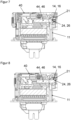
Figur 5 dargestellten Vorraststellung stehen die am Positionssicherungselement 40 angeformten hinteren Stifte 43, 45 unmittelbar vor jeweils einer Ausnehmung 13, 15 in der Wand des ersten Steckverbindergehäuses 11. Unmittelbar dahinter und jeweils in einer Flucht mit den Ausnehmungen 13, 15 befindet sich jeweils eine Ausnehmung 23, 25 in einer Wand des zweiten Steckverbindergehäuses 21. Die Querschnittsform und der Querschnittsgröße der Stifte 43, 45 und der Ausnehmungen 13, 15, 23, 25 sind aneinander angepasst, so dass die Stifte 43, 45 nach einer Verschiebung des Positionssicherungselements 40 in der Endraststellung (Figur 6 ) spielarm in die Ausnehmungen 13, 15, 23, 25 eingreifen. Durch einen Eingriff der beiden Stifte 43, 45 in die Ausnehmungen 13 und 23 einerseits sowie in die Ausnehmungen 15 und 25 andererseits wird so eine erste Arretierung des ersten mit dem zweiten Steckverbindergehäuse 11, 21 hergestellt. - Bei einer Verschiebung des Positionssicherungselements 40 von der Vorraststellung in die Endraststellung werden zugleich die beiden vorderen Stifte 44, 46 in zweite Ausnehmungen 14, 16 am ersten Steckverbindergehäuse 11 sowie in zweite Ausnehmungen 24, 26 am zweiten Steckverbindergehäuse 21 eingesetzt. Diese in den
Figuren 7 und 8 im Schnitt erkennbaren zweiten Ausnehmungen 14, 16 sind hier in Form von Ösen ausgebildet, die an beiden Längsseiten des ersten Steckverbindergehäuses 11 angeformt sind. Nach dem Durchgang durch die Ösen erreichen die vorderen Stifte 44, 46 am zweiten Steckverbindergehäuse 21 angeformte Ausnehmungen 24, 26 und werden darin stabilisiert. - Jeder der vier Stifte 43, 44, 45, 46 taucht somit sowohl durch jeweils eine Ausnehmung 13, 14, 15, 16 des ersten Steckverbindergehäuses 11 als auch durch jeweils eine Ausnehmung 23, 24, 25, 26 des zweiten Steckverbindergehäuses 21
- Das Positionssicherungselement 40 arretiert somit sowohl mit seinen vorderen als auch mit seinen hinteren Stiften 43, 44, 45, 46 das erste und das zweite Steckverbindergehäuse 11, 21 an jeweils zwei einander gegenüberliegenden Stellen des Umfangsbereichs des ersten Steckverbindergehäuses 11, welche beide entlang der Abgangsrichtung der Anschlussleitungen 30 liegen.
- Das am zweiten Steckverbindergehäuse 21 angeordnete Positionssicherungselement 40 schafft so eine stabilisierende mehrfache Verriegelung zwischen den beiden Steckverbindergehäusen 11, 21 ohne dabei den Montageaufwand beim Verbinden oder Trennen der Steckverbinder 10, 20 zu erhöhen.
-
- 10
- erster Steckverbinder
- 11
- erstes Steckverbindergehäuse
- 12
- Steckkontaktelement(e)
- 13,14, 15, 16
- Ausnehmung(en)
- 17
- elektrische Anschlüsse
- 20
- zweiter Steckverbinder
- 21
- zweites Steckverbindergehäuse
- 23, 24, 25, 26
- Ausnehmung(en)
- 30
- Anschlussleitung(en)
- 40
- Positionssicherungselement
- 42
- Rastfeder(n)
- 43, 44, 45, 46
- Stifte
- 47
- Oberseite
- 48
- Seitenteile
- 49
- Rückseite
- 50
- Montagefläche
Claims (2)
- Hochvoltsteckverbinderanordnungmit einem ortsfest angeordneten ersten Steckverbinder (10) mit einem ersten Steckverbindergehäuse (11),mit einem beweglich angeordneten zweiten Steckverbinder (20) mit einem zweiten Steckverbindergehäuse (21),wobei der erste und der zweite Steckverbinder (10, 20) zueinander komplementäre und miteinander verbindbare Steckkontaktelemente (12) aufweisen,und wobei der zweite Steckverbinder (20) mit seinen Steckkontaktelementen verbundene Anschlussleitungen (30) aufweist, deren Abgangsrichtung senkrecht zur Verbindungsrichtung der beiden Steckverbinder (10, 20) verläuft,und wobei der zweite Steckverbinder (20) ein senkrecht zur Verbindungsrichtung verschiebbares Positionssicherungselement (40) aufweist, das bei zusammengefügten Steckverbindern (10, 20) in einer Schiebeposition die beiden Steckverbinder (10, 20) mechanisch miteinander arretiert,dadurch gekennzeichnet,dass das Positionssicherungselement (40) wenigstens zwei Paare von Stiften (43, 44; 45, 46) aufweist, deren Längsachsen in der Verschieberichtung des Positionssicherungselements (40) ausgerichtet sind, und die hinsichtlich der Verschieberichtung des Positionssicherungselements (40) paarweise hintereinander angeordnet sind, unddass in der die Steckverbinder arretierenden Schiebeposition jeder der Stifte (43, 44, 45, 46) des Positionssicherungselements (40) in jeweils eine Ausnehmung (13, 14, 15, 16) am ersten Steckverbinder (10) und in jeweils eine Ausnehmung (23, 24, 25, 26) am zweiten Steckverbinder (20) eingreift.
- Hochvoltsteckverbinderanordnung nach Anspruch 1, dadurch gekennzeichnet, dass das Positionssicherungselement (40) genau zwei Paare von angeformten Stiften (43, 44, 45, 46) aufweist.
Applications Claiming Priority (2)
| Application Number | Priority Date | Filing Date | Title |
|---|---|---|---|
| DE102021000957.6A DE102021000957A1 (de) | 2021-02-23 | 2021-02-23 | Hochvoltsteckverbinderanordnung |
| PCT/EP2022/054335 WO2022180006A1 (de) | 2021-02-23 | 2022-02-22 | Hochvoltsteckverbinderanordnung |
Publications (2)
| Publication Number | Publication Date |
|---|---|
| EP4298698A1 EP4298698A1 (de) | 2024-01-03 |
| EP4298698B1 true EP4298698B1 (de) | 2024-12-11 |
Family
ID=80928880
Family Applications (1)
| Application Number | Title | Priority Date | Filing Date |
|---|---|---|---|
| EP22711917.9A Active EP4298698B1 (de) | 2021-02-23 | 2022-02-22 | Hochvoltsteckverbinderanordnung |
Country Status (9)
| Country | Link |
|---|---|
| US (1) | US20230387628A1 (de) |
| EP (1) | EP4298698B1 (de) |
| JP (1) | JP7735415B2 (de) |
| KR (1) | KR20230147698A (de) |
| CN (1) | CN116918192A (de) |
| DE (1) | DE102021000957A1 (de) |
| ES (1) | ES3013826T3 (de) |
| MX (1) | MX2023009801A (de) |
| WO (1) | WO2022180006A1 (de) |
Families Citing this family (1)
| Publication number | Priority date | Publication date | Assignee | Title |
|---|---|---|---|---|
| WO2024231326A1 (de) * | 2023-05-09 | 2024-11-14 | Stäubli Electrical Connectors Ag | Steckverbinderanordnung |
Family Cites Families (15)
| Publication number | Priority date | Publication date | Assignee | Title |
|---|---|---|---|---|
| US4148538A (en) * | 1978-03-30 | 1979-04-10 | General Motors Corporation | Elastomeric electrical connector |
| US4269075A (en) * | 1979-04-16 | 1981-05-26 | Crist Gerald L | Coupling arrangement for detachably connecting a driven unit to a drive unit |
| US5435742A (en) | 1994-02-14 | 1995-07-25 | Molex Incorporated | Electrical connector position assurance system |
| TW467419U (en) * | 2000-12-30 | 2001-12-01 | Hon Hai Prec Ind Co Ltd | Connector holding structure |
| US6979220B1 (en) * | 2003-06-29 | 2005-12-27 | Card Access, Inc. | Plug locking mechanism |
| DE102005029133A1 (de) * | 2005-06-23 | 2006-12-28 | Dr.Ing.H.C. F. Porsche Ag | Vorrichtung zur Kontaktierung eines Hochstromkabels |
| CN103959572B (zh) | 2011-10-20 | 2016-04-20 | 德尔福国际业务卢森堡公司 | 安全气囊连接器系统 |
| JP2014017135A (ja) * | 2012-07-10 | 2014-01-30 | Tyco Electronics Japan Kk | コネクタ |
| US9059542B2 (en) * | 2013-07-23 | 2015-06-16 | Tyco Electronics Corporation | Quick connect power connector |
| JP2016048654A (ja) | 2014-08-28 | 2016-04-07 | タイコエレクトロニクスジャパン合同会社 | コネクタ組立体 |
| EP3396790A1 (de) | 2017-04-27 | 2018-10-31 | Delphi International Operations Luxembourg S.à r.l. | Verbinderanordnung für sicherheitssysteme |
| DE202018106428U1 (de) | 2018-11-13 | 2019-05-24 | Odu Gmbh & Co. Kg | Koppelverbinder mit einem Schieberteil |
| JP6817271B2 (ja) * | 2018-11-20 | 2021-01-20 | 矢崎総業株式会社 | コネクタ |
| DE102018009478A1 (de) | 2018-12-04 | 2020-06-04 | Kostal Kontakt Systeme Gmbh | Steckverbinderanordnung |
| CN112038837A (zh) * | 2020-09-25 | 2020-12-04 | 深圳市雄韬电源科技股份有限公司 | 一种高压防脱连接器 |
-
2021
- 2021-02-23 DE DE102021000957.6A patent/DE102021000957A1/de active Pending
-
2022
- 2022-02-22 MX MX2023009801A patent/MX2023009801A/es unknown
- 2022-02-22 JP JP2023549905A patent/JP7735415B2/ja active Active
- 2022-02-22 WO PCT/EP2022/054335 patent/WO2022180006A1/de not_active Ceased
- 2022-02-22 KR KR1020237032283A patent/KR20230147698A/ko active Pending
- 2022-02-22 ES ES22711917T patent/ES3013826T3/es active Active
- 2022-02-22 CN CN202280016190.9A patent/CN116918192A/zh active Pending
- 2022-02-22 EP EP22711917.9A patent/EP4298698B1/de active Active
-
2023
- 2023-08-10 US US18/447,375 patent/US20230387628A1/en active Pending
Also Published As
| Publication number | Publication date |
|---|---|
| KR20230147698A (ko) | 2023-10-23 |
| CN116918192A (zh) | 2023-10-20 |
| JP7735415B2 (ja) | 2025-09-08 |
| MX2023009801A (es) | 2023-12-07 |
| DE102021000957A1 (de) | 2022-08-25 |
| EP4298698A1 (de) | 2024-01-03 |
| JP2024506734A (ja) | 2024-02-14 |
| ES3013826T3 (en) | 2025-04-15 |
| US20230387628A1 (en) | 2023-11-30 |
| WO2022180006A1 (de) | 2022-09-01 |
Similar Documents
| Publication | Publication Date | Title |
|---|---|---|
| EP2656450B1 (de) | Steckverbinder | |
| EP2076943B1 (de) | Xlr-kabelsteckverbinder | |
| DE102004038123B4 (de) | Elektrischer Stecker und elektrische Steckeraufnahme | |
| DE102016105504B4 (de) | Montageoptimierter elektrischer Steckverbinder | |
| EP2522052B1 (de) | Federklemme, insbesondere frontklemme | |
| DE69113778T2 (de) | Elektrischer Verbinder mit positiver Einrastung. | |
| DE102009053674A1 (de) | Steckverbinder mit Sekundärsteckverbinder | |
| DE102010029670A1 (de) | Verbinderbaugruppe für einen elektrischen Steckverbinder, elektrischer Steckverbinder und konfektioniertes elektrisches Kabel | |
| WO2014037358A1 (de) | Prüfklemmenblock | |
| WO2008071694A1 (de) | Elektrischer steckverbinder | |
| WO2014041096A1 (de) | Steckverbinderanordnung | |
| EP2780986B1 (de) | Steckverbindung | |
| WO2020114981A1 (de) | Steckverbinderanordnung | |
| DE69507178T2 (de) | Elektrischer Kabelkanal und Verbinder | |
| DE102017128604A1 (de) | Elektrische Steckverbindung zur Datenübertragung | |
| EP4298698B1 (de) | Hochvoltsteckverbinderanordnung | |
| DE102021118454B3 (de) | Elektrischer steckverbinder und elektrisches steckverbindungssystem | |
| EP4078735B1 (de) | Elektrische steckverbindung | |
| EP3994770B1 (de) | Mehrpolige steckverbinderanordnung | |
| WO2014041095A1 (de) | Steckverbinderanordnung | |
| DE102021133011B3 (de) | Verriegelungsvorrichtung für Steckverbindungen sowie Steckverbindung mit einer solchen Verriegelungsvorrichtung | |
| DE102021122636A1 (de) | Steckverbindung | |
| DE102021119480B3 (de) | Elektrischer Steckverbinder und Elektrisches Steckverbindersystem | |
| EP4270675B1 (de) | Festpoliger kontakteinsatz und kontakteinsatzanordnung | |
| DE202009014961U1 (de) | Elektrischer Rechteckwinkelsteckverbinder |
Legal Events
| Date | Code | Title | Description |
|---|---|---|---|
| STAA | Information on the status of an ep patent application or granted ep patent |
Free format text: STATUS: UNKNOWN |
|
| STAA | Information on the status of an ep patent application or granted ep patent |
Free format text: STATUS: THE INTERNATIONAL PUBLICATION HAS BEEN MADE |
|
| PUAI | Public reference made under article 153(3) epc to a published international application that has entered the european phase |
Free format text: ORIGINAL CODE: 0009012 |
|
| STAA | Information on the status of an ep patent application or granted ep patent |
Free format text: STATUS: REQUEST FOR EXAMINATION WAS MADE |
|
| 17P | Request for examination filed |
Effective date: 20230809 |
|
| AK | Designated contracting states |
Kind code of ref document: A1 Designated state(s): AL AT BE BG CH CY CZ DE DK EE ES FI FR GB GR HR HU IE IS IT LI LT LU LV MC MK MT NL NO PL PT RO RS SE SI SK SM TR |
|
| DAV | Request for validation of the european patent (deleted) | ||
| DAX | Request for extension of the european patent (deleted) | ||
| RAP1 | Party data changed (applicant data changed or rights of an application transferred) |
Owner name: KOSTAL KONTAKT SYSTEME GMBH & CO. KG |
|
| GRAP | Despatch of communication of intention to grant a patent |
Free format text: ORIGINAL CODE: EPIDOSNIGR1 |
|
| STAA | Information on the status of an ep patent application or granted ep patent |
Free format text: STATUS: GRANT OF PATENT IS INTENDED |
|
| INTG | Intention to grant announced |
Effective date: 20240930 |
|
| GRAS | Grant fee paid |
Free format text: ORIGINAL CODE: EPIDOSNIGR3 |
|
| GRAA | (expected) grant |
Free format text: ORIGINAL CODE: 0009210 |
|
| STAA | Information on the status of an ep patent application or granted ep patent |
Free format text: STATUS: THE PATENT HAS BEEN GRANTED |
|
| AK | Designated contracting states |
Kind code of ref document: B1 Designated state(s): AL AT BE BG CH CY CZ DE DK EE ES FI FR GB GR HR HU IE IS IT LI LT LU LV MC MK MT NL NO PL PT RO RS SE SI SK SM TR |
|
| REG | Reference to a national code |
Ref country code: GB Ref legal event code: FG4D Free format text: NOT ENGLISH |
|
| REG | Reference to a national code |
Ref country code: CH Ref legal event code: EP |
|
| REG | Reference to a national code |
Ref country code: IE Ref legal event code: FG4D Free format text: LANGUAGE OF EP DOCUMENT: GERMAN |
|
| REG | Reference to a national code |
Ref country code: DE Ref legal event code: R096 Ref document number: 502022002381 Country of ref document: DE |
|
| REG | Reference to a national code |
Ref country code: LT Ref legal event code: MG9D |
|
| PG25 | Lapsed in a contracting state [announced via postgrant information from national office to epo] |
Ref country code: HR Free format text: LAPSE BECAUSE OF FAILURE TO SUBMIT A TRANSLATION OF THE DESCRIPTION OR TO PAY THE FEE WITHIN THE PRESCRIBED TIME-LIMIT Effective date: 20241211 |
|
| PGFP | Annual fee paid to national office [announced via postgrant information from national office to epo] |
Ref country code: DE Payment date: 20250114 Year of fee payment: 4 |
|
| PG25 | Lapsed in a contracting state [announced via postgrant information from national office to epo] |
Ref country code: FI Free format text: LAPSE BECAUSE OF FAILURE TO SUBMIT A TRANSLATION OF THE DESCRIPTION OR TO PAY THE FEE WITHIN THE PRESCRIBED TIME-LIMIT Effective date: 20241211 |
|
| REG | Reference to a national code |
Ref country code: ES Ref legal event code: FG2A Ref document number: 3013826 Country of ref document: ES Kind code of ref document: T3 Effective date: 20250415 |
|
| PG25 | Lapsed in a contracting state [announced via postgrant information from national office to epo] |
Ref country code: BG Free format text: LAPSE BECAUSE OF FAILURE TO SUBMIT A TRANSLATION OF THE DESCRIPTION OR TO PAY THE FEE WITHIN THE PRESCRIBED TIME-LIMIT Effective date: 20241211 |
|
| REG | Reference to a national code |
Ref country code: NL Ref legal event code: MP Effective date: 20241211 |
|
| PGFP | Annual fee paid to national office [announced via postgrant information from national office to epo] |
Ref country code: ES Payment date: 20250304 Year of fee payment: 4 |
|
| PG25 | Lapsed in a contracting state [announced via postgrant information from national office to epo] |
Ref country code: NO Free format text: LAPSE BECAUSE OF FAILURE TO SUBMIT A TRANSLATION OF THE DESCRIPTION OR TO PAY THE FEE WITHIN THE PRESCRIBED TIME-LIMIT Effective date: 20250311 |
|
| PG25 | Lapsed in a contracting state [announced via postgrant information from national office to epo] |
Ref country code: LV Free format text: LAPSE BECAUSE OF FAILURE TO SUBMIT A TRANSLATION OF THE DESCRIPTION OR TO PAY THE FEE WITHIN THE PRESCRIBED TIME-LIMIT Effective date: 20241211 Ref country code: GR Free format text: LAPSE BECAUSE OF FAILURE TO SUBMIT A TRANSLATION OF THE DESCRIPTION OR TO PAY THE FEE WITHIN THE PRESCRIBED TIME-LIMIT Effective date: 20250312 |
|
| PGFP | Annual fee paid to national office [announced via postgrant information from national office to epo] |
Ref country code: AT Payment date: 20250417 Year of fee payment: 4 |
|
| PGFP | Annual fee paid to national office [announced via postgrant information from national office to epo] |
Ref country code: FR Payment date: 20250228 Year of fee payment: 4 Ref country code: CZ Payment date: 20250110 Year of fee payment: 4 |
|
| PGFP | Annual fee paid to national office [announced via postgrant information from national office to epo] |
Ref country code: IT Payment date: 20250228 Year of fee payment: 4 |
|
| PG25 | Lapsed in a contracting state [announced via postgrant information from national office to epo] |
Ref country code: RS Free format text: LAPSE BECAUSE OF FAILURE TO SUBMIT A TRANSLATION OF THE DESCRIPTION OR TO PAY THE FEE WITHIN THE PRESCRIBED TIME-LIMIT Effective date: 20250311 |
|
| PG25 | Lapsed in a contracting state [announced via postgrant information from national office to epo] |
Ref country code: NL Free format text: LAPSE BECAUSE OF FAILURE TO SUBMIT A TRANSLATION OF THE DESCRIPTION OR TO PAY THE FEE WITHIN THE PRESCRIBED TIME-LIMIT Effective date: 20241211 |
|
| PG25 | Lapsed in a contracting state [announced via postgrant information from national office to epo] |
Ref country code: SM Free format text: LAPSE BECAUSE OF FAILURE TO SUBMIT A TRANSLATION OF THE DESCRIPTION OR TO PAY THE FEE WITHIN THE PRESCRIBED TIME-LIMIT Effective date: 20241211 |
|
| PG25 | Lapsed in a contracting state [announced via postgrant information from national office to epo] |
Ref country code: PL Free format text: LAPSE BECAUSE OF FAILURE TO SUBMIT A TRANSLATION OF THE DESCRIPTION OR TO PAY THE FEE WITHIN THE PRESCRIBED TIME-LIMIT Effective date: 20241211 |
|
| PG25 | Lapsed in a contracting state [announced via postgrant information from national office to epo] |
Ref country code: IS Free format text: LAPSE BECAUSE OF FAILURE TO SUBMIT A TRANSLATION OF THE DESCRIPTION OR TO PAY THE FEE WITHIN THE PRESCRIBED TIME-LIMIT Effective date: 20250411 |
|
| PG25 | Lapsed in a contracting state [announced via postgrant information from national office to epo] |
Ref country code: PT Free format text: LAPSE BECAUSE OF FAILURE TO SUBMIT A TRANSLATION OF THE DESCRIPTION OR TO PAY THE FEE WITHIN THE PRESCRIBED TIME-LIMIT Effective date: 20250411 |
|
| PG25 | Lapsed in a contracting state [announced via postgrant information from national office to epo] |
Ref country code: EE Free format text: LAPSE BECAUSE OF FAILURE TO SUBMIT A TRANSLATION OF THE DESCRIPTION OR TO PAY THE FEE WITHIN THE PRESCRIBED TIME-LIMIT Effective date: 20241211 |
|
| PG25 | Lapsed in a contracting state [announced via postgrant information from national office to epo] |
Ref country code: RO Free format text: LAPSE BECAUSE OF FAILURE TO SUBMIT A TRANSLATION OF THE DESCRIPTION OR TO PAY THE FEE WITHIN THE PRESCRIBED TIME-LIMIT Effective date: 20241211 |
|
| PG25 | Lapsed in a contracting state [announced via postgrant information from national office to epo] |
Ref country code: SK Free format text: LAPSE BECAUSE OF FAILURE TO SUBMIT A TRANSLATION OF THE DESCRIPTION OR TO PAY THE FEE WITHIN THE PRESCRIBED TIME-LIMIT Effective date: 20241211 |
|
| PG25 | Lapsed in a contracting state [announced via postgrant information from national office to epo] |
Ref country code: SE Free format text: LAPSE BECAUSE OF FAILURE TO SUBMIT A TRANSLATION OF THE DESCRIPTION OR TO PAY THE FEE WITHIN THE PRESCRIBED TIME-LIMIT Effective date: 20241211 |
|
| REG | Reference to a national code |
Ref country code: DE Ref legal event code: R097 Ref document number: 502022002381 Country of ref document: DE |
|
| PG25 | Lapsed in a contracting state [announced via postgrant information from national office to epo] |
Ref country code: MC Free format text: LAPSE BECAUSE OF FAILURE TO SUBMIT A TRANSLATION OF THE DESCRIPTION OR TO PAY THE FEE WITHIN THE PRESCRIBED TIME-LIMIT Effective date: 20241211 |
|
| REG | Reference to a national code |
Ref country code: CH Ref legal event code: PL |
|
| PG25 | Lapsed in a contracting state [announced via postgrant information from national office to epo] |
Ref country code: DK Free format text: LAPSE BECAUSE OF FAILURE TO SUBMIT A TRANSLATION OF THE DESCRIPTION OR TO PAY THE FEE WITHIN THE PRESCRIBED TIME-LIMIT Effective date: 20241211 |
|
| PG25 | Lapsed in a contracting state [announced via postgrant information from national office to epo] |
Ref country code: LU Free format text: LAPSE BECAUSE OF NON-PAYMENT OF DUE FEES Effective date: 20250222 |
|
| PLBE | No opposition filed within time limit |
Free format text: ORIGINAL CODE: 0009261 |
|
| STAA | Information on the status of an ep patent application or granted ep patent |
Free format text: STATUS: NO OPPOSITION FILED WITHIN TIME LIMIT |
|
| PG25 | Lapsed in a contracting state [announced via postgrant information from national office to epo] |
Ref country code: CH Free format text: LAPSE BECAUSE OF NON-PAYMENT OF DUE FEES Effective date: 20250228 |
|
| 26N | No opposition filed |
Effective date: 20250912 |