EP4296460A2 - Stellantrieb zum bewegen einer möbelklappe - Google Patents
Stellantrieb zum bewegen einer möbelklappe Download PDFInfo
- Publication number
- EP4296460A2 EP4296460A2 EP23208462.4A EP23208462A EP4296460A2 EP 4296460 A2 EP4296460 A2 EP 4296460A2 EP 23208462 A EP23208462 A EP 23208462A EP 4296460 A2 EP4296460 A2 EP 4296460A2
- Authority
- EP
- European Patent Office
- Prior art keywords
- actuating arm
- coupling element
- coupling
- furniture
- actuator
- Prior art date
- Legal status (The legal status is an assumption and is not a legal conclusion. Google has not performed a legal analysis and makes no representation as to the accuracy of the status listed.)
- Granted
Links
Images




Classifications
-
- E—FIXED CONSTRUCTIONS
- E05—LOCKS; KEYS; WINDOW OR DOOR FITTINGS; SAFES
- E05F—DEVICES FOR MOVING WINGS INTO OPEN OR CLOSED POSITION; CHECKS FOR WINGS; WING FITTINGS NOT OTHERWISE PROVIDED FOR, CONCERNED WITH THE FUNCTIONING OF THE WING
- E05F1/00—Closers or openers for wings, not otherwise provided for in this subclass
- E05F1/08—Closers or openers for wings, not otherwise provided for in this subclass spring-actuated, e.g. for horizontally sliding wings
- E05F1/10—Closers or openers for wings, not otherwise provided for in this subclass spring-actuated, e.g. for horizontally sliding wings for swinging wings, e.g. counterbalance
- E05F1/1041—Closers or openers for wings, not otherwise provided for in this subclass spring-actuated, e.g. for horizontally sliding wings for swinging wings, e.g. counterbalance with a coil spring perpendicular to the pivot axis
- E05F1/105—Closers or openers for wings, not otherwise provided for in this subclass spring-actuated, e.g. for horizontally sliding wings for swinging wings, e.g. counterbalance with a coil spring perpendicular to the pivot axis with a compression spring
- E05F1/1058—Closers or openers for wings, not otherwise provided for in this subclass spring-actuated, e.g. for horizontally sliding wings for swinging wings, e.g. counterbalance with a coil spring perpendicular to the pivot axis with a compression spring for counterbalancing
-
- E—FIXED CONSTRUCTIONS
- E05—LOCKS; KEYS; WINDOW OR DOOR FITTINGS; SAFES
- E05F—DEVICES FOR MOVING WINGS INTO OPEN OR CLOSED POSITION; CHECKS FOR WINGS; WING FITTINGS NOT OTHERWISE PROVIDED FOR, CONCERNED WITH THE FUNCTIONING OF THE WING
- E05F3/00—Closers or openers with braking devices, e.g. checks; Construction of pneumatic or liquid braking devices
-
- E—FIXED CONSTRUCTIONS
- E05—LOCKS; KEYS; WINDOW OR DOOR FITTINGS; SAFES
- E05D—HINGES OR SUSPENSION DEVICES FOR DOORS, WINDOWS OR WINGS
- E05D15/00—Suspension arrangements for wings
- E05D15/26—Suspension arrangements for wings for folding wings
- E05D15/262—Suspension arrangements for wings for folding wings folding vertically
-
- E—FIXED CONSTRUCTIONS
- E05—LOCKS; KEYS; WINDOW OR DOOR FITTINGS; SAFES
- E05D—HINGES OR SUSPENSION DEVICES FOR DOORS, WINDOWS OR WINGS
- E05D15/00—Suspension arrangements for wings
- E05D15/40—Suspension arrangements for wings supported on arms movable in vertical planes
-
- E—FIXED CONSTRUCTIONS
- E05—LOCKS; KEYS; WINDOW OR DOOR FITTINGS; SAFES
- E05D—HINGES OR SUSPENSION DEVICES FOR DOORS, WINDOWS OR WINGS
- E05D15/00—Suspension arrangements for wings
- E05D15/40—Suspension arrangements for wings supported on arms movable in vertical planes
- E05D15/401—Suspension arrangements for wings supported on arms movable in vertical planes specially adapted for overhead wings
-
- E—FIXED CONSTRUCTIONS
- E05—LOCKS; KEYS; WINDOW OR DOOR FITTINGS; SAFES
- E05Y—INDEXING SCHEME ASSOCIATED WITH SUBCLASSES E05D AND E05F, RELATING TO CONSTRUCTION ELEMENTS, ELECTRIC CONTROL, POWER SUPPLY, POWER SIGNAL OR TRANSMISSION, USER INTERFACES, MOUNTING OR COUPLING, DETAILS, ACCESSORIES, AUXILIARY OPERATIONS NOT OTHERWISE PROVIDED FOR, APPLICATION THEREOF
- E05Y2201/00—Constructional elements; Accessories therefor
- E05Y2201/20—Brakes; Disengaging means; Holders; Stops; Valves; Accessories therefor
- E05Y2201/21—Brakes
-
- E—FIXED CONSTRUCTIONS
- E05—LOCKS; KEYS; WINDOW OR DOOR FITTINGS; SAFES
- E05Y—INDEXING SCHEME ASSOCIATED WITH SUBCLASSES E05D AND E05F, RELATING TO CONSTRUCTION ELEMENTS, ELECTRIC CONTROL, POWER SUPPLY, POWER SIGNAL OR TRANSMISSION, USER INTERFACES, MOUNTING OR COUPLING, DETAILS, ACCESSORIES, AUXILIARY OPERATIONS NOT OTHERWISE PROVIDED FOR, APPLICATION THEREOF
- E05Y2201/00—Constructional elements; Accessories therefor
- E05Y2201/20—Brakes; Disengaging means; Holders; Stops; Valves; Accessories therefor
- E05Y2201/23—Actuation thereof
- E05Y2201/232—Actuation thereof by automatically acting means
- E05Y2201/24—Actuation thereof by automatically acting means using lost motion
-
- E—FIXED CONSTRUCTIONS
- E05—LOCKS; KEYS; WINDOW OR DOOR FITTINGS; SAFES
- E05Y—INDEXING SCHEME ASSOCIATED WITH SUBCLASSES E05D AND E05F, RELATING TO CONSTRUCTION ELEMENTS, ELECTRIC CONTROL, POWER SUPPLY, POWER SIGNAL OR TRANSMISSION, USER INTERFACES, MOUNTING OR COUPLING, DETAILS, ACCESSORIES, AUXILIARY OPERATIONS NOT OTHERWISE PROVIDED FOR, APPLICATION THEREOF
- E05Y2201/00—Constructional elements; Accessories therefor
- E05Y2201/20—Brakes; Disengaging means; Holders; Stops; Valves; Accessories therefor
- E05Y2201/23—Actuation thereof
- E05Y2201/232—Actuation thereof by automatically acting means
- E05Y2201/242—Actuation thereof by automatically acting means using threshold speed
-
- E—FIXED CONSTRUCTIONS
- E05—LOCKS; KEYS; WINDOW OR DOOR FITTINGS; SAFES
- E05Y—INDEXING SCHEME ASSOCIATED WITH SUBCLASSES E05D AND E05F, RELATING TO CONSTRUCTION ELEMENTS, ELECTRIC CONTROL, POWER SUPPLY, POWER SIGNAL OR TRANSMISSION, USER INTERFACES, MOUNTING OR COUPLING, DETAILS, ACCESSORIES, AUXILIARY OPERATIONS NOT OTHERWISE PROVIDED FOR, APPLICATION THEREOF
- E05Y2201/00—Constructional elements; Accessories therefor
- E05Y2201/60—Suspension or transmission members; Accessories therefor
- E05Y2201/604—Transmission members
-
- E—FIXED CONSTRUCTIONS
- E05—LOCKS; KEYS; WINDOW OR DOOR FITTINGS; SAFES
- E05Y—INDEXING SCHEME ASSOCIATED WITH SUBCLASSES E05D AND E05F, RELATING TO CONSTRUCTION ELEMENTS, ELECTRIC CONTROL, POWER SUPPLY, POWER SIGNAL OR TRANSMISSION, USER INTERFACES, MOUNTING OR COUPLING, DETAILS, ACCESSORIES, AUXILIARY OPERATIONS NOT OTHERWISE PROVIDED FOR, APPLICATION THEREOF
- E05Y2201/00—Constructional elements; Accessories therefor
- E05Y2201/60—Suspension or transmission members; Accessories therefor
- E05Y2201/622—Suspension or transmission members elements
- E05Y2201/71—Toothed gearing
-
- E—FIXED CONSTRUCTIONS
- E05—LOCKS; KEYS; WINDOW OR DOOR FITTINGS; SAFES
- E05Y—INDEXING SCHEME ASSOCIATED WITH SUBCLASSES E05D AND E05F, RELATING TO CONSTRUCTION ELEMENTS, ELECTRIC CONTROL, POWER SUPPLY, POWER SIGNAL OR TRANSMISSION, USER INTERFACES, MOUNTING OR COUPLING, DETAILS, ACCESSORIES, AUXILIARY OPERATIONS NOT OTHERWISE PROVIDED FOR, APPLICATION THEREOF
- E05Y2201/00—Constructional elements; Accessories therefor
- E05Y2201/60—Suspension or transmission members; Accessories therefor
- E05Y2201/622—Suspension or transmission members elements
- E05Y2201/71—Toothed gearing
- E05Y2201/712—Toothed gearing with incomplete toothing
-
- E—FIXED CONSTRUCTIONS
- E05—LOCKS; KEYS; WINDOW OR DOOR FITTINGS; SAFES
- E05Y—INDEXING SCHEME ASSOCIATED WITH SUBCLASSES E05D AND E05F, RELATING TO CONSTRUCTION ELEMENTS, ELECTRIC CONTROL, POWER SUPPLY, POWER SIGNAL OR TRANSMISSION, USER INTERFACES, MOUNTING OR COUPLING, DETAILS, ACCESSORIES, AUXILIARY OPERATIONS NOT OTHERWISE PROVIDED FOR, APPLICATION THEREOF
- E05Y2600/00—Mounting or coupling arrangements for elements provided for in this subclass
-
- E—FIXED CONSTRUCTIONS
- E05—LOCKS; KEYS; WINDOW OR DOOR FITTINGS; SAFES
- E05Y—INDEXING SCHEME ASSOCIATED WITH SUBCLASSES E05D AND E05F, RELATING TO CONSTRUCTION ELEMENTS, ELECTRIC CONTROL, POWER SUPPLY, POWER SIGNAL OR TRANSMISSION, USER INTERFACES, MOUNTING OR COUPLING, DETAILS, ACCESSORIES, AUXILIARY OPERATIONS NOT OTHERWISE PROVIDED FOR, APPLICATION THEREOF
- E05Y2800/00—Details, accessories and auxiliary operations not otherwise provided for
- E05Y2800/40—Physical or chemical protection
-
- E—FIXED CONSTRUCTIONS
- E05—LOCKS; KEYS; WINDOW OR DOOR FITTINGS; SAFES
- E05Y—INDEXING SCHEME ASSOCIATED WITH SUBCLASSES E05D AND E05F, RELATING TO CONSTRUCTION ELEMENTS, ELECTRIC CONTROL, POWER SUPPLY, POWER SIGNAL OR TRANSMISSION, USER INTERFACES, MOUNTING OR COUPLING, DETAILS, ACCESSORIES, AUXILIARY OPERATIONS NOT OTHERWISE PROVIDED FOR, APPLICATION THEREOF
- E05Y2900/00—Application of doors, windows, wings or fittings thereof
- E05Y2900/20—Application of doors, windows, wings or fittings thereof for furniture, e.g. cabinets
Definitions
- the invention further relates to a piece of furniture with a furniture body that is movable relative to the furniture body stored furniture flap and with an actuator of the type to be described for moving the furniture flap.
- Actuators for moving furniture flaps usually have at least one pivotally mounted actuating arm and an energy storage device in the form of a spring device for applying force to the actuating arm.
- the weight of the furniture flap can be at least partially compensated for by the energy storage, so that the movement of the furniture flap is made easier for a person.
- the actuating arm is subjected to extremely high preload forces from the energy storage device in the direction of the open position. Critical situations can arise in particular if the furniture flap is not yet connected to the actuating arm. In such a case, there is no counterweight acting on the actuating arm, which means that the actuating arm can swing massively due to the force of the energy accumulator and cause injuries to people and damage to objects.
- actuators for moving furniture flaps which are equipped with a centrifugal clutch to prevent an uncontrolled deflection of the actuating arm towards the open position.
- the centrifugal clutch ensures that the actuating arm can be moved in a controlled manner below a predetermined pivoting speed. Above the predetermined pivoting speed of the actuating arm, the actuating arm is automatically locked by the centrifugal clutch, whereby the actuating arm is in its pivoting position is locked and cannot swing further towards the open position.
- the object of the present invention is to provide an actuator of the type mentioned at the outset while avoiding the disadvantages discussed above.
- the second coupling element has at least one freewheel section separate from the engagement section, the first coupling element being arranged within the freewheel section of the second coupling element in the closed position of the actuating arm, whereby the two coupling elements are decoupled from one another in the closed position of the actuating arm.
- the second coupling element has at least one freewheel section, which prevents engagement, in particular a positive locking, of the two coupling elements with one another in the closed position of the actuating arm and/or in a pivoting region immediately upstream of the closed position of the actuating arm.
- the first coupling element can be placed on the freewheel section of the second coupling element, whereby the surface of the freewheel section can be designed to be essentially toothless or essentially smooth.
- the freewheel section can also have a different surface finish, but in any case it should be ensured that locking between the two coupling elements is not possible in the closed position of the actuating arm.
- the two coupling elements are connected by the freewheel section of the second coupling element within a pivot angle range of the actuating arm, which is between the closed position of the actuating arm and an open position of the actuating arm of a maximum of 30°, preferably a maximum of 20°, are decoupled from one another.
- the engagement section of the second coupling element can, for example, have counter-toothing for positive locking with the first coupling element.
- the freewheel section on the other hand, can form a substantially smooth contact surface, against which the first coupling element can be placed in the closed position of the actuating arm.
- Fig. 1 shows a furniture 1 with a furniture body 2 in a side view, with a furniture flap 3 being movably mounted relative to the furniture body 2 by an actuator 4.
- the furniture flap 3 is designed in two parts and comprises a first partial flap 3a, which is pivotally attached to an underside of a cover plate 2a of the furniture body 2 by hinges 10.
- the second partial flap 3b is connected in an articulated manner to the first partial flap 3a.
- the actuator 4 has a housing 5 to be fastened to the furniture body 2 and at least one actuating arm 7, which is pivotally mounted on the housing 5 and is preferably designed to be adjustable in length, for moving the furniture flap 3.
- the actuating arm 7 is pivotally connected to a fitting part 9 via a joint axis 8, the fitting part 9 being fastened to an inside of the second partial flap 3b - preferably via a mounting plate.
- Fig. 2 shows a side view of the furniture 1 according to Fig. 1 with a furniture flap 3 closed in relation to the furniture body 2.
- the actuator 4 has an energy storage 11 ( Fig. 3a ) to apply force to the actuating arm 7, whereby the weight of the furniture flap 3 can be at least partially compensated.
- the actuator 4 has a coupling device 19 (not visible here) for braking or preventing a pivoting movement of the at least one actuating arm 7, so that an unintentional opening or deflection of the empty actuating arm 7, to which no furniture flap 3 is yet attached, is caused by an in Force of the energy storage device 11 acting in the opening direction can be avoided.
- the coupling device 19 is not active because the pivoting speed of the actuating arm 7 for a furniture flap 3 mounted on the actuating arm 7 is always well below a predetermined critical value.
- the coupling device 19 of the actuator 4 can jam in the closed position of the furniture flap 3 shown, so that the furniture flap 3 cannot be moved in either the opening or closing direction and the jamming of the coupling device 19 cannot be released.
- the energy accumulator 11 is movably connected via an attack point 16 to an intermediate lever 12 which can be pivoted about an axis of rotation 13, with a pressure roller 14 being rotatably mounted on the intermediate lever 12.
- a control contour 15 is formed on the coupling piece 17, with the pressure roller 14 of the intermediate lever 12 being movable along the control contour 15 of the coupling piece 17 when the actuating arm 7 moves about the axis of rotation 6.
- Fig. 4a shows a side view of the actuator 4, with the actuating arm 7 (ie the coupling piece 17) being locked in an open position of approximately 20° by the coupling device 19.
- Fig. 4b shows the in Fig. 4a framed area in an enlarged view, the actuating arm 7 being exceeded by exceeding the predetermined pivoting speed by locking the two first coupling elements 23a, 23b with the second Coupling element 24 is locked in a form-fitting manner.
- the locking of the actuating arm 7 can be released by manually pressing the actuating arm 7 towards the closed position.
- the two first coupling elements 23a, 23b can then be unlocked from the second coupling element 24 by the force of the spring elements 27a, 27b.
- the rotor 29 has two pivot bearings 31a, 31b for supporting the first coupling elements 23a, 23b.
- the second coupling element 24 has an engagement section 25 for releasably locking the first coupling element 23a and a freewheel section 26 separate from the engagement section 25, which prevents locking between the first coupling element 23a and the second coupling element 24 in the closed position of the actuating arm 7.
- the other coupling element 23b is spaced apart from the coupling element 23a in an axial direction of the shaft 30, wherein the coupling element 23b can be brought into engagement with a further second coupling element 24a.
- the further coupling element 24a also has a freewheel section 26a, which is arranged offset by 180 ° relative to the freewheel section 26 of the other coupling element 24.
Landscapes
- Engineering & Computer Science (AREA)
- Mechanical Engineering (AREA)
- Closing And Opening Devices For Wings, And Checks For Wings (AREA)
- Cabinets, Racks, Or The Like Of Rigid Construction (AREA)
Abstract
- zumindest einen um eine Drehachse (6) schwenkbar gelagerten Stellarm (7) zum Bewegen der Möbelklappe (3), wobei der zumindest eine Stellarm (7) zwischen einer Schließstellung, welche in einem Montagezustand der Möbelklappe (3) einer Schließstellung der Möbelklappe (3) relativ zum Möbelkorpus (2) entspricht, und einer Offenstellung bewegbar gelagert ist,
- einen Kraftspeicher (11) zur Kraftbeaufschlagung des zumindest einen Stellarmes (7),
- eine Kupplungsvorrichtung (19) zum Bremsen oder Verhindern einer Schwenkbewegung des zumindest einen Stellarmes (7), wobei die Kupplungsvorrichtung (19) zumindest ein bewegbar gelagertes erstes Kupplungselement (23a, 23b) mit einer Verzahnung (34a, 34b) aufweist, wobei das zumindest eine erste Kupplungselement (23a, 23b) bei einer Überschreitung einer vorgegebenen Schwenkgeschwindigkeit des Stellarmes (7) mit einem zweiten Kupplungselement (24) in Eingriff bringbar ist, wodurch die Schwenkbewegung des zumindest einen Stellarmes (7) gebremst oder verhindert wird, wobei das zweite Kupplungselement (24) wenigstens einen Eingriffsabschnitt (25) aufweist, durch welchen die beiden Kupplungselemente (23a, 23b, 24) miteinander in Eingriff bringbar sind,
wobei das zweite Kupplungselement (24) wenigstens einen vom Eingriffsabschnitt (25) gesonderten Freilaufabschnitt (26) aufweist, wobei das erste Kupplungselement (23a, 23b) in der Schließstellung des Stellarmes (7) innerhalb des Freilaufabschnitts (26) des zweiten Kupplungselementes (24) angeordnet ist, wodurch die beiden Kupplungselemente (23a, 23b, 24) in der Schließstellung des Stellarmes (7) voneinander entkoppelt sind.
Description
- Die vorliegende Erfindung bezieht sich auf einen Stellantrieb zum Bewegen einer relativ zu einem Möbelkorpus bewegbar gelagerten Möbelklappe, umfassend:
- zumindest einen um eine Drehachse schwenkbar gelagerten Stellarm zum Bewegen der Möbelklappe, wobei der zumindest eine Stellarm zwischen einer Schließstellung, welche in einem Montagezustand der Möbelklappe einer Schließstellung der Möbelklappe relativ zum Möbelkorpus entspricht, und einer Offenstellung bewegbar gelagert ist,
- einen Kraftspeicher zur Kraftbeaufschlagung des zumindest einen Stellarmes,
- eine Kupplungsvorrichtung zum Bremsen oder Verhindern einer Schwenkbewegung des zumindest einen Stellarmes, wobei die Kupplungsvorrichtung zumindest ein bewegbar gelagertes erstes Kupplungselement mit einer Verzahnung aufweist, wobei das zumindest eine erste Kupplungselement bei einer Überschreitung einer vorgegebenen Schwenkgeschwindigkeit des Stellarmes mit einem zweiten Kupplungselement in Eingriff bringbar ist, wodurch die Schwenkbewegung des zumindest einen Stellarmes gebremst oder verhindert wird, wobei das zweite Kupplungselement wenigstens einen Eingriffsabschnitt aufweist, durch welchen die beiden Kupplungselemente miteinander in Eingriff bringbar sind.
- Im Weiteren betrifft die Erfindung ein Möbel mit einem Möbelkorpus, einer relativ zum Möbelkorpus bewegbar gelagerten Möbelklappe und mit einem Stellantrieb der zu beschreibenden Art zum Bewegen des Möbelklappe.
- Stellantriebe zum Bewegen von Möbelklappen weisen üblicherweise zumindest einen schwenkbar gelagerten Stellarm und einen Kraftspeicher in Form einer Federvorrichtung zur Kraftbeaufschlagung des Stellarmes auf. Durch den Kraftspeicher ist das Gewicht der Möbelklappe zumindest teilweise kompensierbar, sodass die Bewegung der Möbelklappe für eine Person erleichtert wird. Der Stellarm ist je nach Größe und Gewicht der Möbelklappe mit extrem hohen Vorspannkräften des Kraftspeichers in Richtung Offenstellung beaufschlagt. Kritische Situationen können sich insbesondere dann ergeben, wenn die Möbelklappe noch nicht mit dem Stellarm verbunden ist. In einem solchen Fall wirkt auf den Stellarm auch kein Gegengewicht, wodurch der Stellarm durch die Kraft des Kraftspeichers massiv ausschlagen und Verletzungen an Personen und Beschädigungen an Objekten verursachen kann.
- In der
WO 2006/069412 A1 und in derWO 2010/051569 A1 sind Stellantriebe zum Bewegen von Möbelklappen offenbart, welche mit einer Fliehkraftkupplung zur Verhinderung eines unkontrollierten Ausschlages des Stellarmes in Richtung Offenstellung ausgestattet sind. Die Fliehkraftkupplung stellt sicher, dass der Stellarm unterhalb einer vorgegebenen Schwenkgeschwindigkeit in einer kontrollierten Weise bewegbar ist. Oberhalb der vorgegebenen Schwenkgeschwindigkeit des Stellarmes wird eine selbsttätige Verriegelung des Stellarmes durch die Fliehkraftkupplung herbeigeführt, wodurch der Stellarm in seiner Schwenklage verriegelt wird und nicht weiter in Richtung Offenstellung ausschlagen kann. - In der Praxis können sich insofern Probleme mit der Fliehkraftkupplung ergeben, wenn der Stellantrieb bereits am Möbel vormontiert ist und der Stellarm einerseits am Möbelkorpus und andererseits an der Möbelklappe angelenkt ist. Wenn sich die Möbelklappe in einer geschlossenen Stellung relativ zum Möbelkorpus befindet, so kann es vorkommen, dass sich die Kupplungselemente der Fliehkraftkupplung in einer unerwünschten Weise miteinander verkeilen, beispielsweise durch einen Transport oder durch eine Kippbewegung des Möbelkorpus bei seiner Montage. Der Stellarm ist durch die blockierte Fliehkraftkupplung in seiner geschlossenen Lage arretiert und kann durch die am Möbelkorpus anliegende Möbelklappe auch nicht mehr weiter in Richtung Schließstellung gedrückt werden, wodurch sich die Verkeilung der Fliehkraftkupplung und die Blockierung des Stellarmes lösen lassen könnte. Ein Öffnen der Möbelklappe ist dann oft nur mehr mit einhergehenden Beschädigungen der Möbelklappe oder des Stellantriebes möglich.
- Aufgabe der vorliegenden Erfindung ist es, einen Stellantrieb der eingangs erwähnten Gattung unter Vermeidung der oben diskutierten Nachteile anzugeben.
- Dies wird erfindungsgemäß durch die Merkmale des Patentanspruchs 1 gelöst. Weitere vorteilhafte Ausführungsbeispiele der Erfindung sind in den abhängigen Ansprüchen definiert.
- Gemäß der Erfindung ist vorgesehen, dass das zweite Kupplungselement wenigstens einen vom Eingriffsabschnitt gesonderten Freilaufabschnitt aufweist, wobei das erste Kupplungselement in der Schließstellung des Stellarmes innerhalb des Freilaufabschnitts des zweiten Kupplungselementes angeordnet ist, wodurch die beiden Kupplungselemente in der Schließstellung des Stellarmes voneinander entkoppelt sind.
- Mit anderen Worten weist das zweite Kupplungselement zumindest einen Freilaufabschnitt auf, welcher einen Eingriff, insbesondere eine formschlüssige Verriegelung, der beiden Kupplungselemente zueinander in der Schließstellung des Stellarmes und/oder in einem der Schließstellung des Stellarmes unmittelbar vorgelagerten Schwenkbereich verhindert.
- In der Schließstellung des Stellarmes ist das erste Kupplungselement am Freilaufabschnitt des zweiten Kupplungselementes anlegbar, wobei die Oberfläche des Freilaufabschnittes im Wesentlichen zahnlos oder im Wesentlichen glatt ausgeführt werden kann. Der Freilaufabschnitt kann auch eine andere Oberflächenbeschaffenheit aufweisen, jedenfalls sollte aber sichergestellt sein, dass in der Schließstellung des Stellarmes eine Verriegelung zwischen den beiden Kupplungselementen nicht möglich ist.
- Gemäß einem Ausführungsbeispiel kann vorgesehen sein, dass die beiden Kupplungselemente durch den Freilaufabschnitt des zweiten Kupplungselementes innerhalb eines Schwenkwinkelbereiches des Stellarmes, welcher sich zwischen der Schließstellung des Stellarmes und einer Offenstellung des Stellarmes von maximal 30°, vorzugsweise maximal 20°, ergibt, voneinander entkoppelt sind.
- Gemäß einem Ausführungsbeispiel der Erfindung kann vorgesehen sein, das zweite Kupplungselement eine im Wesentlichen ringförmige Innenkontur aufweist, wobei sowohl der Eingriffsabschnitt als auch der Freilaufabschnitt an der ringförmigen Innenkontur des zweiten Kupplungselementes angeordnet oder ausgebildet sind.
- Der Eingriffsabschnitt des zweiten Kupplungselementes kann beispielsweise eine Gegenverzahnung zur formschlüssigen Verriegelung mit dem ersten Kupplungselement aufweisen. Der Freilaufabschnitt kann hingegen eine im Wesentlichen glatte Anlagefläche ausbilden, an welcher das erste Kupplungselement in der Schließstellung des Stellarmes anlegbar ist.
- Weitere Einzelheiten und Vorteile der vorliegenden Erfindung ergeben sich aus der nachfolgenden Figurenbeschreibung.
- Fig. 1
- zeigt eine Seitenansicht eines Möbels mit einem Möbelkorpus, einer in einer Offenstellung befindlichen Möbelklappe und mit einem Stellantrieb zum Bewegen der Möbelklappe,
- Fig. 2
- zeigt das Möbel gemäß
Fig. 1 , wobei die Möbelklappe eine Schließstellung relativ zum Möbelkorpus einnimmt, - Fig. 3a-3c
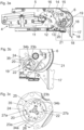
- zeigen den Stellantrieb in einer Seitenansicht sowie zwei vergrößerte Detaildarstellungen hierzu, wobei sich der Stellarm in einer Schließstellung befindet,
- Fig. 4a-4c
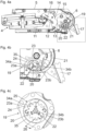
- zeigt den Stellantrieb in einer Seitenansicht sowie zwei vergrößerte Detaildarstellungen hierzu, wobei sich der Stellarm in einer verriegelten Offenstellung befindet,
- Fig. 5a, 5b
- zeigt eine perspektivische Ansicht des mit dem Stellarm zu verbindenden Koppelstücks des Stellantriebes sowie eine vergrößerte Detaildarstellung hierzu,
- Fig. 6a, 6b
- zeigt die Kupplungsvorrichtung in einer Explosionsansicht sowie eine vergrößerte Detaildarstellung hierzu.
-
Fig. 1 zeigt ein Möbel 1 mit einem Möbelkorpus 2 in einer Seitenansicht, wobei eine Möbelklappe 3 durch einen Stellantrieb 4 relativ zum Möbelkorpus 2 bewegbar gelagert ist. Im gezeigten Ausführungsbeispiel ist die Möbelklappe 3 zweiteilig ausgebildet und umfasst eine erste Teilklappe 3a, welche durch Scharniere 10 an einer Unterseite einer Deckplatte 2a des Möbelkorpus 2 schwenkbar befestigt ist. Die zweite Teilklappe 3b ist mit der ersten Teilklappe 3a gelenkig verbunden. Der Stellantrieb 4 weist ein am Möbelkorpus 2 zu befestigendes Gehäuse 5 und zumindest einen am Gehäuse 5 schwenkbar gelagerten, vorzugsweise längenverstellbar ausgebildeten, Stellarm 7 zum Bewegen der Möbelklappe 3 auf. Der Stellarm 7 ist über eine Gelenkachse 8 schwenkbar mit einem Beschlagteil 9 verbunden, wobei das Beschlagteil 9 - vorzugsweise über eine Montageplatte - an einer Innenseite der zweiten Teilklappe 3b zu befestigen ist. -
Fig. 2 zeigt eine Seitenansicht des Möbels 1 gemäßFig. 1 mit einer in Bezug zum Möbelkorpus 2 geschlossenen Möbelklappe 3. Der Stellantrieb 4 weist einen Kraftspeicher 11 (Fig. 3a ) zur Kraftbeaufschlagung des Stellarmes 7 auf, wodurch das Gewicht der Möbelklappe 3 zumindest teilweise kompensierbar ist. Überdies weist der Stellantrieb 4 eine (hier nicht ersichtliche) Kupplungsvorrichtung 19 zum Bremsen oder Verhindern einer Schwenkbewegung des zumindest einen Stellarmes 7 auf, sodass ein unbeabsichtigtes Öffnen oder Ausschlagen des leeren Stellarmes 7, an dem also noch keine Möbelklappe 3 befestigt ist, durch eine in Öffnungsrichtung wirkende Kraft des Kraftspeichers 11 vermieden werden kann. Ist die Möbelklappe 3 am Stellarm 7 befestigt, so ist die Kupplungsvorrichtung 19 nicht aktiv, weil die Schwenkgeschwindigkeit des Stellarmes 7 bei einer am Stellarm 7 montierten Möbelklappe 3 stets weit unterhalb eines vorgegebenen kritischen Wertes liegt. Die Kupplungsvorrichtung 19 des Stellantriebes 4 kann sich allerdings in der gezeigten Schließstellung der Möbelklappe 3 verklemmen, sodass sich die Möbelklappe 3 weder in Öffnungsrichtung noch in Schließrichtung bewegen lässt und die Verklemmung der Kupplungsvorrichtung 19 nicht gelöst werden kann. -
Fig. 3a zeigt den Stellantrieb 4 mit dem am Möbelkorpus 2 zu befestigenden Gehäuse 5 in einer Seitenansicht. Der (hier nicht gezeigte) Stellarm 7 ist mit einem um die Drehachse 6 drehbaren Koppelstück 17 lösbar verbindbar, wobei das Koppelstück 17 zur formschlüssigen Befestigung des Stellarmes 7 mehrere Ausnehmungen 18 aufweist. Zur Kraftbeaufschlagung des Stellarmes 7 ist ein Kraftspeicher 11 vorgesehen, welcher zumindest eine Schraubenfeder, beispielsweise zumindest eine Druckfeder oder zumindest eine Schraubenfeder) aufweist. Gemäß einer bevorzugten Ausführungsform weist der Kraftspeicher 11 ein Federpaket mit mehreren parallel angeordneten Druckfedern auf. Der Kraftspeicher 11 ist über eine Angriffsstelle 16 mit einem um eine Drehachse 13 schwenkbaren Zwischenhebel 12 beweglich verbunden, wobei am Zwischenhebel 12 eine Druckrolle 14 drehbar gelagert ist. Am Koppelstück 17 ist eine Steuerkontur 15 ausgebildet, wobei die Druckrolle 14 des Zwischenhebels 12 bei einer Bewegung des Stellarmes 7 um die Drehachse 6 entlang der Steuerkontur 15 des Koppelstückes 17 verfahrbar ist. - Der Stellantrieb 4 weist eine Kupplungsvorrichtung 19 zum Bremsen oder Verhindern einer Schwenkbewegung des zumindest einen Stellarmes 7 auf, wodurch ein unbeabsichtigtes Ausschlagen des Stellarmes 7 aufgrund einer auf den Stellarm 7 ausgeübten Kraft des Kraftspeichers 11 in Richtung der Offenstellung verhindert ist. Die Kupplungsvorrichtung 19 kann beispielsweise eine Fliehkraftkupplung aufweisen. Die Kupplungsvorrichtung 19 ist durch ein um die Rotationsachse 22 drehbares Zahnrad 20 antreibbar, wobei das Zahnrad 20 bei einer Bewegung des Stellarmes 7 um die Drehachse 6 entlang einer, vorzugsweise bogenförmig ausgebildeten, Zahnschiene 21 verfahrbar ist. Die Zahnschiene 21 ist am Gehäuse 5 des Stellantriebes 4 angeordnet oder ausgebildet. Das Zahnrad 20 und die Zahnschiene 21 bilden ein Übersetzungsgetriebe, durch welches eine Schwenkgeschwindigkeit des Stellarmes 7 über einen Bereich des Schwenkweges des Stellarmes 7 auf eine höhere Drehgeschwindigkeit einer auf der Rotationsachse 22 gelagerten Welle 30 (
Fig. 6a ) übersetzbar ist. Bei einem Übersetzungsverhältnis des Übersetzungsgetriebes von 1:4 bedeutet dies, dass eine Winkeländerung des Stellarmes 7 um 15° zu einer vierfachen Winkeländerung der auf der Rotationsachse 22 gelagerten Welle 30 führt. Die Welle 30 wird dabei also um 60° verdreht. Auf diese Weise kann die Reaktionszeit der als Fliehkraftkupplung ausgebildeten Kupplungsvorrichtung 19 erheblich verkürzt werden. -
Fig. 3b zeigt den inFig. 3a eingerahmten Bereich in einer vergrößerten Ansicht. Bei einer Bewegung des Stellarmes 7 (d.h. des Kupplungsstückes 17) läuft das Zahnrad 20 entlang der Zahnschiene 21 ab. Die Kupplungsvorrichtung 19 weist zumindest ein bewegbar gelagertes erstes Kupplungselement 23a, 23b (Fig. 3c ) auf, welches bei einer Überschreitung einer vorgegebenen Schwenkgeschwindigkeit des Stellarmes 7 mit einem zweiten Kupplungselement 24 in Eingriff bringbar ist, wodurch die Schwenkbewegung des Stellarmes 7 gebremst oder verhindert wird. -
Fig. 3c zeigt eine vergrößerte Detaildarstellung der Kupplungsvorrichtung 19, wobei zwei erste Kupplungselemente 23a, 23b auf einer gemeinsamen, um die Rotationsachse 22 drehbaren Welle 30 angeordnet sind. Die beiden ersten Kupplungselemente 23a, 23b sind in einer axialen Richtung der Welle 30 voneinander beabstandet und sind durch das an der Zahnschiene 21 ablaufende Zahnrad 20 um die Rotationsachse 22 antreibbar. Die Kupplungselemente 23a, 23b weisen jeweils eine Verzahnung 34a, 34b auf, welche bei Überschreitung einer vorgegebenen Schwenkgeschwindigkeit des Stellarmes 7 mit einer Gegenverzahnung 35 eines am zweiten Kupplungselement 24 angeordneten Eingriffsabschnitts 25 formschlüssig verriegelbar sind. Zu erkennen ist, dass am zweiten Kupplungselement 24 zumindest ein Freilaufabschnitt 26 angeordnet ist, welcher eine Verriegelung des ersten Kupplungselementes 23a mit dem zweiten Kupplungselement 24 in der gezeigten Schließstellung des Stellarmes 7 verhindert. Für den beispielhaften Fall, dass sich der Winkelbereich des Freilaufabschnittes 26 über einen Winkelbereich von 28° erstreckt, so ist eine Verriegelung des Stellarmes 7 bei dem bereits erwähnten Übersetzungsverhältnis des Übersetzungsgetriebes von 1:4 innerhalb eines Winkelbereiches von 7° nicht möglich. Der Freilaufabschnitt 26 kann eine bogenförmige ausgebildete, glatte Kontur aufweisen, welche frei von Vertiefungen oder Erhebungen ausgebildet ist. - Die ersten Kupplungselemente 23a, 23b sind durch Federelemente 27a, 27b in Richtung einer von dem zweiten Kupplungselement 24 entkoppelten Stellung vorgespannt. Die Federelemente 27a, 27b dienen dazu, die Kupplungselemente 23a, 23b in eine kompakte Ruhelage zu drücken und eine definierte Auslösekraft bereitzustellen. Erst nach Überwindung der definierten Auslösekraft sind die beiden ersten Kupplungselemente 23a, 23b mit dem zweiten Kupplungselement 24 lösbar verriegelbar.
-
Fig. 4a zeigt eine Seitenansicht des Stellantriebes 4, wobei der Stellarm 7 (d.h. das Koppelstück 17) in einer Offenstellung von etwa 20° durch die Kupplungsvorrichtung 19 verriegelt ist.Fig. 4b zeigt den inFig. 4a eingerahmten Bereich in einer vergrößerten Ansicht, wobei der Stellarm 7 durch eine Überschreitung der vorgegebenen Schwenkgeschwindigkeit durch eine Verriegelung der beiden ersten Kupplungselemente 23a, 23b mit dem zweiten Kupplungselement 24 formschlüssig verriegelt ist. Ausgehend von der inFig. 4b gezeigten Stellung kann die Verriegelung des Stellarmes 7 gelöst werden, indem der Stellarm 7 manuell in Richtung der Schließstellung gedrückt wird. Die beiden ersten Kupplungselemente 23a, 23b sind dann durch die Kraft der Federelemente 27a, 27b vom zweiten Kupplungselement 24 entriegelbar. -
Fig. 4c zeigt eine vergrößerte Darstellung der Kupplungsvorrichtung 19, wobei die Verzahnungen 34a, 34b der ersten Kupplungselemente 23a, 23b in die Gegenverzahnung 35 des Eingriffsabschnittes 25 des zweiten Kupplungselementes 24 eingreifen. Der Eingriffsabschnitt 25 kann sich beispielsweise über einen Winkelbereich von 330° erstrecken, während sich der Freilaufabschnitt 26 über 30° erstreckt. -
Fig. 5a zeigt eine perspektivische Ansicht des mit dem Stellarm 7 zu verbindenden Koppelstückes 17 des Stellantriebes 4. Das Koppelstück 17 weist mehrere Ausnehmungen 18 auf, in welchen in einem montierten Zustand des Stellarmes 7 allfällige Befestigungselemente des Stellarmes 7, insbesondere Stifte und/oder ein federbelasteter Kipphebel des Stellarmes 7, aufgenommen sind. Die Steuerkontur 15 zur verfahrbaren Lagerung der Druckrolle 14 wird durch einen Umfangsrand zweier Scheibenteile 28a, 28b gebildet, welche parallel voneinander beabstandet sind. Der Stellarm 7 ist zusammen mit dem Koppelstück 17 um die Drehachse 6 schwenkbar gelagert, wobei das um die Rotationsachse 22 drehbare Zahnrad 20 entlang der gebogenen Zahnschiene 21 des Stellantriebes 4 verfahrbar ist. Der Stellarm 7, an welchem keine Möbelklappe 3 montiert ist, ist bei Überschreitung einer vorgegebenen Schwenkgeschwindigkeit durch die Kupplungsvorrichtung 19 formschlüssig verriegelbar. Die Drehachse 6 des Stellarmes 7 und die Rotationsachse 22 des Zahnrades 20 sind im Wesentlichen parallel voneinander beabstandet.Fig. 5b zeigt den inFig. 5a eingekreisten Bereich in einer vergrößerten Ansicht. -
Fig. 6a zeigt die Kupplungsvorrichtung 19 in einer eine Explosionsansicht, wobei die Kupplungsvorrichtung 19 zwischen den beiden Scheibenteilen 28a, 28b aufgenommen ist und sich bei einer Schwenkbewegung des Stellarmes 7 um die Drehachse 6 verdreht. An beiden Seiten der Scheibenteile 28a, 28b sind Zahnräder 20 angeordnet, welche jeweils mit einer Zahnschiene 21 (Fig. 3a ) kämmen. Die Zahnräder 20 sind über die Welle 30 miteinander bewegungsgekoppelt, wobei an der Welle 30 ein drehbarer Rotor 29 zur bewegbaren Lagerung der ersten Kupplungselemente 23a, 23b angeordnet ist. Die ersten Kupplungselemente 23a, 23b sind um 180° versetzt am Rotor 29 gelagert. Der Rotor 29 weist zwei Drehlager 31a, 31b zur Lagerung der ersten Kupplungselemente 23a, 23b auf. Das zweite Kupplungselement 24 weist einen Eingriffsabschnitt 25 zur lösbaren Verriegelung des ersten Kupplungselementes 23a und einen vom Eingriffsabschnitt 25 gesonderten Freilaufabschnitt 26 auf, welcher in der Schließstellung des Stellarmes 7 eine Verriegelung zwischen dem ersten Kupplungselement 23a und dem zweiten Kupplungselement 24 verhindert. Das andere Kupplungselement 23b ist in einer axialen Richtung der Welle 30 vom Kupplungselement 23a beabstandet, wobei das Kupplungselement 23b mit einem weiteren zweiten Kupplungselement 24a in Eingriff bringbar ist. Das weitere Kupplungselement 24a weist ebenfalls einen Freilaufabschnitt 26a auf, welcher relativ zum Freilaufabschnitt 26 des anderen Kupplungselementes 24 um 180° versetzt angeordnet ist. -
Fig. 6b zeigt den inFig. 6a eingekreisten Bereich in einer vergrößerten Ansicht. Die ersten Kupplungselemente 23a, 23b sind jeweils zweiteilig ausgeführt und sind jeweils durch Nieten 32a, 32b miteinander verbunden. Der Rotor 29 weist zwei Drehlager 31a, 31b auf, in welchen Drehteile 33a, 33b der ersten Kupplungselemente 23a, 23b aufnehmbar sind.
Claims (14)
- Stellantrieb (4) zum Bewegen einer relativ zu einem Möbelkorpus (2) bewegbar gelagerten Möbelklappe (3), umfassend:- zumindest einen um eine Drehachse (6) schwenkbar gelagerten Stellarm (7) zum Bewegen der Möbelklappe (3), wobei der zumindest eine Stellarm (7) zwischen einer Schließstellung, welche in einem Montagezustand der Möbelklappe (3) einer Schließstellung der Möbelklappe (3) relativ zum Möbelkorpus (2) entspricht, und einer Offenstellung bewegbar gelagert ist,- einen Kraftspeicher (11) zur Kraftbeaufschlagung des zumindest einen Stellarmes (7),- eine Kupplungsvorrichtung (19) zum Bremsen oder Verhindern einer Schwenkbewegung des zumindest einen Stellarmes (7), wobei die Kupplungsvorrichtung (19) zumindest ein bewegbar gelagertes erstes Kupplungselement (23a, 23b) mit einer Verzahnung (34a, 34b) aufweist, wobei das zumindest eine erste Kupplungselement (23a, 23b) bei einer Überschreitung einer vorgegebenen Schwenkgeschwindigkeit des Stellarmes (7) mit einem zweiten Kupplungselement (24) in Eingriff bringbar ist, wodurch die Schwenkbewegung des zumindest einen Stellarmes (7) gebremst oder verhindert wird, wobei das zweite Kupplungselement (24) wenigstens einen Eingriffsabschnitt (25) aufweist, durch welchen die beiden Kupplungselemente (23a, 23b, 24) miteinander in Eingriff bringbar sind,dadurch gekennzeichnet, dass das zweite Kupplungselement (24) wenigstens einen vom Eingriffsabschnitt (25) gesonderten Freilaufabschnitt (26) aufweist, wobei das erste Kupplungselement (23a, 23b) in der Schließstellung des Stellarmes (7) innerhalb des Freilaufabschnitts (26) des zweiten Kupplungselementes (24) angeordnet ist, wodurch die beiden Kupplungselemente (23a, 23b, 24) in der Schließstellung des Stellarmes (7) voneinander entkoppelt sind.
- Stellantrieb nach Anspruch 1, dadurch gekennzeichnet, dass die beiden Kupplungselemente (23a, 23b, 24) durch den Freilaufabschnitt (26) des zweiten Kupplungselementes (24) innerhalb eines Schwenkwinkelbereiches des Stellarmes (7), welcher sich zwischen der Schließstellung des Stellarmes (7) und einer Offenstellung des Stellarmes (7) von maximal 30°, vorzugsweise maximal 20°, ergibt, voneinander entkoppelt sind.
- Stellantrieb nach Anspruch 1 oder 2, dadurch gekennzeichnet, dass das zumindest eine erste Kupplungselement (23a, 23b) an einem Rotor (29) bewegbar gelagert ist, wobei der Rotor (29) um eine Rotationsachse (22) drehbar gelagert ist.
- Stellantrieb nach Anspruch 3, dadurch gekennzeichnet, dass der Rotor (29) wenigstens ein Drehlager (31a, 31b) zur Aufnahme eines Drehteiles (33a, 33b) des ersten Kupplungselementes (23a, 23b) aufweist.
- Stellantrieb nach Anspruch 3 oder 4, dadurch gekennzeichnet, dass die Rotationsachse (22) des Rotors (29) und die Drehachse (6) des Stellarmes (7) parallel voneinander beabstandet sind.
- Stellantrieb nach einem der Ansprüche 1 bis 5, dadurch gekennzeichnet, dass das erste Kupplungselement (23a, 23b) durch eine Kraft eines Federelementes (27a) in Richtung einer von dem zweiten Kupplungselement (24) entkoppelten Stellung vorgespannt ist.
- Stellantrieb nach einem der Ansprüche 1 bis 6, dadurch gekennzeichnet, dass der Stellantrieb (4) ein Übersetzungsgetriebe aufweist, durch welches eine Schwenkgeschwindigkeit des Stellarmes (7) über zumindest einen Bereich des Schwenkweges des Stellarmes (7) auf eine höhere Rotationsgeschwindigkeit des ersten Kupplungselementes (23a) übersetzbar ist.
- Stellantrieb nach Anspruch 7, dadurch gekennzeichnet, dass das Übersetzungsgetriebe wenigstens ein Zahnrad (20) zum Antreiben des ersten Kupplungselementes (23a, 23b) aufweist, wobei das Zahnrad (20) bei einer Schwenkbewegung des Stellarmes (7) um die Drehachse (6) entlang einer, vorzugsweise bogenförmigen, Zahnschiene (21) des Stellantriebes (4) bewegbar ist.
- Stellantrieb nach einem der Ansprüche 1 bis 8, dadurch gekennzeichnet, dass das erste Kupplungselement (23a, 23b) eine Verzahnung (34a, 34b) und dass der Eingriffsabschnitt (25) des zweiten Kupplungselementes (24) eine, vorzugsweise bogenförmig ausgebildete, Gegenverzahnung (35) aufweist, wobei die Verzahnung (34a, 34b) des ersten Kupplungselementes (23a, 23b) und die Gegenverzahnung (35) des zweiten Kupplungselementes (24) formschlüssig miteinander in Eingriff bringbar sind.
- Stellantrieb nach einem der Ansprüche 1 bis 9, dadurch gekennzeichnet, dass das zweite Kupplungselement (24) eine im Wesentlichen ringförmige Innenkontur aufweist, wobei sowohl der Eingriffsabschnitt (25) als auch der Freilaufabschnitt (26) an der ringförmigen Innenkontur des zweiten Kupplungselementes (24) angeordnet oder ausgebildet sind.
- Stellantrieb nach einem der Ansprüche 1 bis 10, dadurch gekennzeichnet, dass zumindest zwei erste Kupplungselemente (23a, 23b) vorgesehen sind, welche jeweils mit einem Eingriffsabschnitt (26, 26a) eines zweiten Kupplungselementes (24, 24a) in Eingriff bringbar sind.
- Stellantrieb nach Anspruch 11, dadurch gekennzeichnet, dass die beiden ersten Kupplungselemente (23a, 23b) um 180° versetzt am Rotor (29) angeordnet sind.
- Möbel (1) mit einem Möbelkorpus (2), einer relativ zum Möbelkorpus (2) bewegbar gelagerten Möbelklappe (3) und mit einem Stellantrieb (4) nach einem der Ansprüche 1 bis 12 zum Bewegen der Möbelklappe (3).
- Möbel nach Anspruch 13, dadurch gekennzeichnet, dass die Möbelklappe (3) in einer Schließstellung den Möbelkorpus (2) verdeckt und in einer Offenstellung eine angehobene Position relativ zum Möbelkorpus (2) einnimmt.
Applications Claiming Priority (3)
| Application Number | Priority Date | Filing Date | Title |
|---|---|---|---|
| ATA50082/2019A AT522109B1 (de) | 2019-01-31 | 2019-01-31 | Stellantrieb zum Bewegen einer Möbelklappe |
| EP20702187.4A EP3918166B1 (de) | 2019-01-31 | 2020-01-16 | Stellantrieb zum bewegen einer möbelklappe |
| PCT/AT2020/060007 WO2020154751A1 (de) | 2019-01-31 | 2020-01-16 | Stellantrieb zum bewegen einer möbelklappe |
Related Parent Applications (1)
| Application Number | Title | Priority Date | Filing Date |
|---|---|---|---|
| EP20702187.4A Division EP3918166B1 (de) | 2019-01-31 | 2020-01-16 | Stellantrieb zum bewegen einer möbelklappe |
Publications (3)
| Publication Number | Publication Date |
|---|---|
| EP4296460A2 true EP4296460A2 (de) | 2023-12-27 |
| EP4296460A3 EP4296460A3 (de) | 2024-03-13 |
| EP4296460B1 EP4296460B1 (de) | 2025-03-12 |
Family
ID=69326306
Family Applications (2)
| Application Number | Title | Priority Date | Filing Date |
|---|---|---|---|
| EP20702187.4A Active EP3918166B1 (de) | 2019-01-31 | 2020-01-16 | Stellantrieb zum bewegen einer möbelklappe |
| EP23208462.4A Active EP4296460B1 (de) | 2019-01-31 | 2020-01-16 | Stellantrieb zum bewegen einer möbelklappe |
Family Applications Before (1)
| Application Number | Title | Priority Date | Filing Date |
|---|---|---|---|
| EP20702187.4A Active EP3918166B1 (de) | 2019-01-31 | 2020-01-16 | Stellantrieb zum bewegen einer möbelklappe |
Country Status (8)
| Country | Link |
|---|---|
| US (1) | US11725444B2 (de) |
| EP (2) | EP3918166B1 (de) |
| JP (1) | JP7216217B2 (de) |
| CN (1) | CN113366184B (de) |
| AT (1) | AT522109B1 (de) |
| ES (2) | ES3034898T3 (de) |
| HU (2) | HUE065783T2 (de) |
| WO (1) | WO2020154751A1 (de) |
Families Citing this family (9)
| Publication number | Priority date | Publication date | Assignee | Title |
|---|---|---|---|---|
| IT201800004535A1 (it) * | 2018-04-16 | 2019-10-16 | Ante incernierate per armadi, cabine armadio e mobili in genere con dispositivi di smorzamento e richiamo magnetici | |
| AT522109B1 (de) * | 2019-01-31 | 2025-03-15 | Blum Gmbh Julius | Stellantrieb zum Bewegen einer Möbelklappe |
| AT522458B1 (de) * | 2019-05-17 | 2020-11-15 | Blum Gmbh Julius | Möbelbeschlag |
| AT523303B1 (de) * | 2019-12-19 | 2023-04-15 | Blum Gmbh Julius | Führungsvorrichtung zur Führung eines Möbelteils |
| AT524341B1 (de) * | 2020-10-22 | 2023-09-15 | Blum Gmbh Julius | Möbelbeschlag mit Mehrgelenkmechanismus |
| AT525029A1 (de) | 2021-04-30 | 2022-11-15 | Blum Gmbh Julius | Elektromotorischer Möbelantrieb |
| JP1749540S (ja) | 2022-07-25 | 2023-07-27 | 家具用部品 | |
| USD1056697S1 (en) * | 2022-07-25 | 2025-01-07 | Julius Blum Gmbh | Furniture fitting |
| DE102024115834A1 (de) * | 2024-06-06 | 2025-12-11 | Flap Competence Center Kft | Hebelarm für einen möbelbeschlag zum gelenkigen verbinden eines bewegbaren möbelteils mit einem möbelkorpus |
Citations (2)
| Publication number | Priority date | Publication date | Assignee | Title |
|---|---|---|---|---|
| WO2006069412A1 (de) | 2004-12-28 | 2006-07-06 | Julius Blum Gmbh | Stellantrieb mit zumindest eine stellarm |
| WO2010051569A1 (de) | 2008-11-06 | 2010-05-14 | Julius Blum Gmbh | Montagesicherung für einen stellantrieb einer möbelklappe |
Family Cites Families (31)
| Publication number | Priority date | Publication date | Assignee | Title |
|---|---|---|---|---|
| DE2801618C3 (de) * | 1978-01-14 | 1981-08-27 | Hack, Eugen, Ing.(grad.), 8500 Nürnberg | Gelenksperre |
| US4678042A (en) * | 1985-09-27 | 1987-07-07 | Tamer Corporation | Method and apparatus for cutting an athletic field line |
| JPS63206584A (ja) * | 1987-02-20 | 1988-08-25 | 株式会社三協精機製作所 | ドアクロ−ザ− |
| KR890002514A (ko) * | 1987-07-10 | 1989-04-10 | 야마다 로꾸이찌 | 도어 체크(door closer) |
| JPH01151682A (ja) * | 1987-12-04 | 1989-06-14 | Sankyo Seiki Mfg Co Ltd | ドアクローザー |
| JPH0638781B2 (ja) * | 1988-08-19 | 1994-05-25 | 株式会社三協精機製作所 | 便器等の調速装置 |
| US4984666A (en) | 1988-04-14 | 1991-01-15 | Kabushiki Kaisha Sankyo Seiki Seisakusho | Speed governor for toilet or the like |
| JPH0270879A (ja) * | 1988-09-06 | 1990-03-09 | Sankyo Seiki Mfg Co Ltd | ドアクローザー |
| JPH08319772A (ja) * | 1995-05-25 | 1996-12-03 | Tateyama Alum Ind Co Ltd | 自動折曲ドア装置 |
| DE10027570A1 (de) * | 2000-06-02 | 2001-12-06 | Bayerische Motoren Werke Ag | Scharnier |
| AT7500U1 (de) * | 2004-02-09 | 2005-04-25 | Blum Gmbh Julius | Stellarmantrieb für klappen von schränken |
| AT502944A1 (de) | 2005-03-21 | 2007-06-15 | Blum Gmbh Julius | Möbel mit einem möbelkorpus und wenigstens einer hochbewegbaren klappe |
| US8944021B2 (en) * | 2007-05-08 | 2015-02-03 | Dolmar Gmbh | Starter device for a motor driven machine |
| AT506519B1 (de) * | 2008-03-06 | 2012-10-15 | Blum Gmbh Julius | Stellantrieb für eine möbelklappe mit einer montagesicherung für den leeren stellarm |
| AT507651B1 (de) | 2008-11-19 | 2013-09-15 | Blum Gmbh Julius | Stellantrieb für bewegbare möbelteile |
| US20110203122A1 (en) * | 2010-02-19 | 2011-08-25 | Lyndon Henry Holcomb | Kct injury prevention chain saw |
| ITMI20110297A1 (it) * | 2011-02-28 | 2012-08-29 | Salice Arturo Spa | Sistema di sollevamento per ante di un mobile oscillanti attorno ad un asse orizzontale |
| AT511099B1 (de) * | 2011-04-29 | 2012-09-15 | Blum Gmbh Julius | Möbel mit einem möbelkorpus und einer faltklappe |
| WO2016120835A1 (en) * | 2015-01-29 | 2016-08-04 | Cultraro Automazione Engineering S.R.L. | Rotary damper with unidirectional coupling |
| EP3109389B1 (de) * | 2015-06-26 | 2017-10-18 | Locinox | Vorrichtung zum schliessen eines drehflügels |
| AT16333U1 (de) * | 2016-03-11 | 2019-07-15 | Blum Gmbh Julius | Stellantrieb zum Antrieb eines bewegbar gelagerten Möbelteils |
| DE102017108197B4 (de) * | 2017-04-18 | 2025-07-17 | Hettich-Oni Gmbh & Co. Kg | Möbel |
| WO2018192819A1 (de) * | 2017-04-18 | 2018-10-25 | Hettich-Oni Gmbh & Co. Kg | Möbelplatte mit einem klappenbeschlag und möbelkorpus sowie möbel mit einer derartigen möbelplatte |
| AT519935B1 (de) * | 2017-05-12 | 2025-02-15 | Blum Gmbh Julius | Möbelantriebssystem |
| DE102017114774A1 (de) * | 2017-07-03 | 2019-01-03 | Hettich-Oni Gmbh & Co. Kg | Klappenbeschlag und Möbel |
| DE102017114772A1 (de) * | 2017-07-03 | 2019-01-03 | Hettich-Oni Gmbh & Co. Kg | Klappenbeschlag und Möbel |
| DE102017114776A1 (de) * | 2017-07-03 | 2019-01-03 | Hettich-Oni Gmbh & Co. Kg | Dämpferanordnung und Klappenbeschlag |
| DE102017114775A1 (de) * | 2017-07-03 | 2019-01-03 | Hettich-Oni Gmbh & Co. Kg | Klappenbeschlag und Möbel |
| AT522109B1 (de) * | 2019-01-31 | 2025-03-15 | Blum Gmbh Julius | Stellantrieb zum Bewegen einer Möbelklappe |
| AT522457B1 (de) * | 2019-05-17 | 2020-11-15 | Blum Gmbh Julius | Möbelbeschlag |
| AT522446B1 (de) * | 2019-05-17 | 2020-11-15 | Blum Gmbh Julius | Möbelantrieb |
-
2019
- 2019-01-31 AT ATA50082/2019A patent/AT522109B1/de active
-
2020
- 2020-01-16 ES ES23208462T patent/ES3034898T3/es active Active
- 2020-01-16 EP EP20702187.4A patent/EP3918166B1/de active Active
- 2020-01-16 HU HUE20702187A patent/HUE065783T2/hu unknown
- 2020-01-16 CN CN202080011739.6A patent/CN113366184B/zh active Active
- 2020-01-16 WO PCT/AT2020/060007 patent/WO2020154751A1/de not_active Ceased
- 2020-01-16 EP EP23208462.4A patent/EP4296460B1/de active Active
- 2020-01-16 ES ES20702187T patent/ES2970987T3/es active Active
- 2020-01-16 JP JP2021544591A patent/JP7216217B2/ja active Active
- 2020-01-16 HU HUE23208462A patent/HUE071408T2/hu unknown
-
2021
- 2021-07-29 US US17/388,289 patent/US11725444B2/en active Active
Patent Citations (2)
| Publication number | Priority date | Publication date | Assignee | Title |
|---|---|---|---|---|
| WO2006069412A1 (de) | 2004-12-28 | 2006-07-06 | Julius Blum Gmbh | Stellantrieb mit zumindest eine stellarm |
| WO2010051569A1 (de) | 2008-11-06 | 2010-05-14 | Julius Blum Gmbh | Montagesicherung für einen stellantrieb einer möbelklappe |
Also Published As
| Publication number | Publication date |
|---|---|
| ES2970987T3 (es) | 2024-06-03 |
| JP2022519077A (ja) | 2022-03-18 |
| HUE071408T2 (hu) | 2025-08-28 |
| CN113366184B (zh) | 2022-10-25 |
| WO2020154751A1 (de) | 2020-08-06 |
| EP3918166B1 (de) | 2023-11-15 |
| US11725444B2 (en) | 2023-08-15 |
| ES3034898T3 (en) | 2025-08-26 |
| AT522109B1 (de) | 2025-03-15 |
| AT522109A1 (de) | 2020-08-15 |
| EP4296460B1 (de) | 2025-03-12 |
| EP3918166A1 (de) | 2021-12-08 |
| US20210355729A1 (en) | 2021-11-18 |
| CN113366184A (zh) | 2021-09-07 |
| EP4296460A3 (de) | 2024-03-13 |
| HUE065783T2 (hu) | 2024-06-28 |
| JP7216217B2 (ja) | 2023-01-31 |
Similar Documents
| Publication | Publication Date | Title |
|---|---|---|
| EP3918166B1 (de) | Stellantrieb zum bewegen einer möbelklappe | |
| EP3621489B1 (de) | Schwenkbeschlag und möbel | |
| EP2342409B1 (de) | Montagesicherung für einen stellantrieb einer möbelklappe | |
| DE69700026T2 (de) | Höhenverstellvorrichtung für einen Fahrzeugsitz | |
| EP2459829B1 (de) | Stellantrieb für ein bewegbares möbelteil | |
| AT502941B1 (de) | Stellantrieb zum antrieb einer klappe eines möbels | |
| DE3434905C2 (de) | ||
| EP3488064B1 (de) | Antriebsanordnung einer verschlusselementanordnung | |
| EP2347076B1 (de) | Stellantrieb für bewegbare möbelteile | |
| AT506519B1 (de) | Stellantrieb für eine möbelklappe mit einer montagesicherung für den leeren stellarm | |
| DE102009029858A1 (de) | Baugruppe mit Rastbeschlag und Freischwenkmechanik | |
| EP1261793A1 (de) | Stufenloser türfeststeller | |
| WO2015149743A1 (de) | Betätigungseinrichtung für ein kraftfahrzeugschloss | |
| EP1309468B1 (de) | Betätigungsvorrichtung für einen fahrzeugsitz-einsteller | |
| WO2010133538A1 (de) | Rastbeschlag mit einem einlegering | |
| EP4003897B1 (de) | Hebezeug | |
| DE20112976U1 (de) | Schwenkbeschlag | |
| DE2810119A1 (de) | Gelenkverbindung, insbesondere fuer fahrzeugsitze | |
| DE102009005044B4 (de) | Verstellvorrichtung zum Verstellen eines Fahrzeugsitzteils | |
| EP2748028B1 (de) | Verstellbeschlag mit einem axialsperrsystem zur ablaufsicherung | |
| WO2012065814A1 (de) | Selbstsperrende schrittschaltmechanik für eine verstellvorrichtung eines fahrzeugsitzes | |
| EP2640918B1 (de) | Türeinheit | |
| DE102022206199B4 (de) | Stufenlose Bremsvorrichtung eines Autositzes | |
| EP2976972B1 (de) | Auflagerelement einer unterfederung eines sitz- oder liegemöbels | |
| DE29814456U1 (de) | Manuell betätigbare Antriebsvorrichtung für einen Drehgelenkbeschlag |
Legal Events
| Date | Code | Title | Description |
|---|---|---|---|
| PUAI | Public reference made under article 153(3) epc to a published international application that has entered the european phase |
Free format text: ORIGINAL CODE: 0009012 |
|
| STAA | Information on the status of an ep patent application or granted ep patent |
Free format text: STATUS: THE APPLICATION HAS BEEN PUBLISHED |
|
| AC | Divisional application: reference to earlier application |
Ref document number: 3918166 Country of ref document: EP Kind code of ref document: P |
|
| AK | Designated contracting states |
Kind code of ref document: A2 Designated state(s): AL AT BE BG CH CY CZ DE DK EE ES FI FR GB GR HR HU IE IS IT LI LT LU LV MC MK MT NL NO PL PT RO RS SE SI SK SM TR |
|
| REG | Reference to a national code |
Ref legal event code: R079 Free format text: PREVIOUS MAIN CLASS: E05D0015400000 Ref country code: DE Ref legal event code: R079 Ref document number: 502020010610 Country of ref document: DE Free format text: PREVIOUS MAIN CLASS: E05D0015400000 Ipc: E05D0015260000 |
|
| PUAL | Search report despatched |
Free format text: ORIGINAL CODE: 0009013 |
|
| AK | Designated contracting states |
Kind code of ref document: A3 Designated state(s): AL AT BE BG CH CY CZ DE DK EE ES FI FR GB GR HR HU IE IS IT LI LT LU LV MC MK MT NL NO PL PT RO RS SE SI SK SM TR |
|
| RIC1 | Information provided on ipc code assigned before grant |
Ipc: E05D 15/40 20060101ALI20240208BHEP Ipc: E05F 1/10 20060101ALI20240208BHEP Ipc: E05D 15/26 20060101AFI20240208BHEP |
|
| P01 | Opt-out of the competence of the unified patent court (upc) registered |
Effective date: 20240215 |
|
| STAA | Information on the status of an ep patent application or granted ep patent |
Free format text: STATUS: REQUEST FOR EXAMINATION WAS MADE |
|
| 17P | Request for examination filed |
Effective date: 20240805 |
|
| RBV | Designated contracting states (corrected) |
Designated state(s): AL AT BE BG CH CY CZ DE DK EE ES FI FR GB GR HR HU IE IS IT LI LT LU LV MC MK MT NL NO PL PT RO RS SE SI SK SM TR |
|
| GRAP | Despatch of communication of intention to grant a patent |
Free format text: ORIGINAL CODE: EPIDOSNIGR1 |
|
| STAA | Information on the status of an ep patent application or granted ep patent |
Free format text: STATUS: GRANT OF PATENT IS INTENDED |
|
| GRAS | Grant fee paid |
Free format text: ORIGINAL CODE: EPIDOSNIGR3 |
|
| GRAA | (expected) grant |
Free format text: ORIGINAL CODE: 0009210 |
|
| STAA | Information on the status of an ep patent application or granted ep patent |
Free format text: STATUS: THE PATENT HAS BEEN GRANTED |
|
| INTG | Intention to grant announced |
Effective date: 20250120 |
|
| AC | Divisional application: reference to earlier application |
Ref document number: 3918166 Country of ref document: EP Kind code of ref document: P |
|
| AK | Designated contracting states |
Kind code of ref document: B1 Designated state(s): AL AT BE BG CH CY CZ DE DK EE ES FI FR GB GR HR HU IE IS IT LI LT LU LV MC MK MT NL NO PL PT RO RS SE SI SK SM TR |
|
| REG | Reference to a national code |
Ref country code: GB Ref legal event code: FG4D Free format text: NOT ENGLISH |
|
| REG | Reference to a national code |
Ref country code: CH Ref legal event code: EP |
|
| REG | Reference to a national code |
Ref country code: DE Ref legal event code: R096 Ref document number: 502020010610 Country of ref document: DE |
|
| REG | Reference to a national code |
Ref country code: IE Ref legal event code: FG4D Free format text: LANGUAGE OF EP DOCUMENT: GERMAN |
|
| PG25 | Lapsed in a contracting state [announced via postgrant information from national office to epo] |
Ref country code: RS Free format text: LAPSE BECAUSE OF FAILURE TO SUBMIT A TRANSLATION OF THE DESCRIPTION OR TO PAY THE FEE WITHIN THE PRESCRIBED TIME-LIMIT Effective date: 20250612 |
|
| PG25 | Lapsed in a contracting state [announced via postgrant information from national office to epo] |
Ref country code: FI Free format text: LAPSE BECAUSE OF FAILURE TO SUBMIT A TRANSLATION OF THE DESCRIPTION OR TO PAY THE FEE WITHIN THE PRESCRIBED TIME-LIMIT Effective date: 20250312 |
|
| REG | Reference to a national code |
Ref country code: LT Ref legal event code: MG9D |
|
| PG25 | Lapsed in a contracting state [announced via postgrant information from national office to epo] |
Ref country code: NO Free format text: LAPSE BECAUSE OF FAILURE TO SUBMIT A TRANSLATION OF THE DESCRIPTION OR TO PAY THE FEE WITHIN THE PRESCRIBED TIME-LIMIT Effective date: 20250612 |
|
| PG25 | Lapsed in a contracting state [announced via postgrant information from national office to epo] |
Ref country code: HR Free format text: LAPSE BECAUSE OF FAILURE TO SUBMIT A TRANSLATION OF THE DESCRIPTION OR TO PAY THE FEE WITHIN THE PRESCRIBED TIME-LIMIT Effective date: 20250312 |
|
| REG | Reference to a national code |
Ref country code: NL Ref legal event code: MP Effective date: 20250312 |
|
| PG25 | Lapsed in a contracting state [announced via postgrant information from national office to epo] |
Ref country code: LV Free format text: LAPSE BECAUSE OF FAILURE TO SUBMIT A TRANSLATION OF THE DESCRIPTION OR TO PAY THE FEE WITHIN THE PRESCRIBED TIME-LIMIT Effective date: 20250312 |
|
| PG25 | Lapsed in a contracting state [announced via postgrant information from national office to epo] |
Ref country code: GR Free format text: LAPSE BECAUSE OF FAILURE TO SUBMIT A TRANSLATION OF THE DESCRIPTION OR TO PAY THE FEE WITHIN THE PRESCRIBED TIME-LIMIT Effective date: 20250613 Ref country code: BG Free format text: LAPSE BECAUSE OF FAILURE TO SUBMIT A TRANSLATION OF THE DESCRIPTION OR TO PAY THE FEE WITHIN THE PRESCRIBED TIME-LIMIT Effective date: 20250312 |
|
| PG25 | Lapsed in a contracting state [announced via postgrant information from national office to epo] |
Ref country code: NL Free format text: LAPSE BECAUSE OF FAILURE TO SUBMIT A TRANSLATION OF THE DESCRIPTION OR TO PAY THE FEE WITHIN THE PRESCRIBED TIME-LIMIT Effective date: 20250312 |
|
| REG | Reference to a national code |
Ref country code: ES Ref legal event code: FG2A Ref document number: 3034898 Country of ref document: ES Kind code of ref document: T3 Effective date: 20250826 |
|
| REG | Reference to a national code |
Ref country code: HU Ref legal event code: AG4A Ref document number: E071408 Country of ref document: HU |
|
| PG25 | Lapsed in a contracting state [announced via postgrant information from national office to epo] |
Ref country code: SE Free format text: LAPSE BECAUSE OF FAILURE TO SUBMIT A TRANSLATION OF THE DESCRIPTION OR TO PAY THE FEE WITHIN THE PRESCRIBED TIME-LIMIT Effective date: 20250312 |
|
| PG25 | Lapsed in a contracting state [announced via postgrant information from national office to epo] |
Ref country code: SM Free format text: LAPSE BECAUSE OF FAILURE TO SUBMIT A TRANSLATION OF THE DESCRIPTION OR TO PAY THE FEE WITHIN THE PRESCRIBED TIME-LIMIT Effective date: 20250312 |
|
| PG25 | Lapsed in a contracting state [announced via postgrant information from national office to epo] |
Ref country code: PT Free format text: LAPSE BECAUSE OF FAILURE TO SUBMIT A TRANSLATION OF THE DESCRIPTION OR TO PAY THE FEE WITHIN THE PRESCRIBED TIME-LIMIT Effective date: 20250714 |
|
| PG25 | Lapsed in a contracting state [announced via postgrant information from national office to epo] |
Ref country code: PL Free format text: LAPSE BECAUSE OF FAILURE TO SUBMIT A TRANSLATION OF THE DESCRIPTION OR TO PAY THE FEE WITHIN THE PRESCRIBED TIME-LIMIT Effective date: 20250312 |
|
| PG25 | Lapsed in a contracting state [announced via postgrant information from national office to epo] |
Ref country code: CZ Free format text: LAPSE BECAUSE OF FAILURE TO SUBMIT A TRANSLATION OF THE DESCRIPTION OR TO PAY THE FEE WITHIN THE PRESCRIBED TIME-LIMIT Effective date: 20250312 Ref country code: EE Free format text: LAPSE BECAUSE OF FAILURE TO SUBMIT A TRANSLATION OF THE DESCRIPTION OR TO PAY THE FEE WITHIN THE PRESCRIBED TIME-LIMIT Effective date: 20250312 |
|
| PG25 | Lapsed in a contracting state [announced via postgrant information from national office to epo] |
Ref country code: RO Free format text: LAPSE BECAUSE OF FAILURE TO SUBMIT A TRANSLATION OF THE DESCRIPTION OR TO PAY THE FEE WITHIN THE PRESCRIBED TIME-LIMIT Effective date: 20250312 |
|
| PG25 | Lapsed in a contracting state [announced via postgrant information from national office to epo] |
Ref country code: SK Free format text: LAPSE BECAUSE OF FAILURE TO SUBMIT A TRANSLATION OF THE DESCRIPTION OR TO PAY THE FEE WITHIN THE PRESCRIBED TIME-LIMIT Effective date: 20250312 |
|
| PG25 | Lapsed in a contracting state [announced via postgrant information from national office to epo] |
Ref country code: IS Free format text: LAPSE BECAUSE OF FAILURE TO SUBMIT A TRANSLATION OF THE DESCRIPTION OR TO PAY THE FEE WITHIN THE PRESCRIBED TIME-LIMIT Effective date: 20250712 |
|
| REG | Reference to a national code |
Ref country code: DE Ref legal event code: R097 Ref document number: 502020010610 Country of ref document: DE |
|
| PG25 | Lapsed in a contracting state [announced via postgrant information from national office to epo] |
Ref country code: DK Free format text: LAPSE BECAUSE OF FAILURE TO SUBMIT A TRANSLATION OF THE DESCRIPTION OR TO PAY THE FEE WITHIN THE PRESCRIBED TIME-LIMIT Effective date: 20250312 |
|
| PLBE | No opposition filed within time limit |
Free format text: ORIGINAL CODE: 0009261 |
|
| STAA | Information on the status of an ep patent application or granted ep patent |
Free format text: STATUS: NO OPPOSITION FILED WITHIN TIME LIMIT |
|
| REG | Reference to a national code |
Ref country code: CH Ref legal event code: L10 Free format text: ST27 STATUS EVENT CODE: U-0-0-L10-L00 (AS PROVIDED BY THE NATIONAL OFFICE) Effective date: 20260121 |
|
| 26N | No opposition filed |
Effective date: 20251215 |
|
| PGFP | Annual fee paid to national office [announced via postgrant information from national office to epo] |
Ref country code: HU Payment date: 20260115 Year of fee payment: 7 |
|
| PGFP | Annual fee paid to national office [announced via postgrant information from national office to epo] |
Ref country code: ES Payment date: 20260210 Year of fee payment: 7 |
|
| PGFP | Annual fee paid to national office [announced via postgrant information from national office to epo] |
Ref country code: DE Payment date: 20260127 Year of fee payment: 7 |
|
| PGFP | Annual fee paid to national office [announced via postgrant information from national office to epo] |
Ref country code: AT Payment date: 20260127 Year of fee payment: 7 |
|
| PGFP | Annual fee paid to national office [announced via postgrant information from national office to epo] |
Ref country code: IT Payment date: 20260123 Year of fee payment: 7 |
|
| PGFP | Annual fee paid to national office [announced via postgrant information from national office to epo] |
Ref country code: TR Payment date: 20260107 Year of fee payment: 7 |