EP4296301A1 - Extruder für thermische zersetzung, system für thermische zersetzung, herstellungsverfahren und entladungsverfahren für zersetzungsgas - Google Patents
Extruder für thermische zersetzung, system für thermische zersetzung, herstellungsverfahren und entladungsverfahren für zersetzungsgas Download PDFInfo
- Publication number
- EP4296301A1 EP4296301A1 EP21926765.5A EP21926765A EP4296301A1 EP 4296301 A1 EP4296301 A1 EP 4296301A1 EP 21926765 A EP21926765 A EP 21926765A EP 4296301 A1 EP4296301 A1 EP 4296301A1
- Authority
- EP
- European Patent Office
- Prior art keywords
- thermal decomposition
- polymer
- hopper
- extruder
- cylinder
- Prior art date
- Legal status (The legal status is an assumption and is not a legal conclusion. Google has not performed a legal analysis and makes no representation as to the accuracy of the status listed.)
- Pending
Links
Images








Classifications
-
- B—PERFORMING OPERATIONS; TRANSPORTING
- B29—WORKING OF PLASTICS; WORKING OF SUBSTANCES IN A PLASTIC STATE IN GENERAL
- B29B—PREPARATION OR PRETREATMENT OF THE MATERIAL TO BE SHAPED; MAKING GRANULES OR PREFORMS; RECOVERY OF PLASTICS OR OTHER CONSTITUENTS OF WASTE MATERIAL CONTAINING PLASTICS
- B29B7/00—Mixing; Kneading
- B29B7/30—Mixing; Kneading continuous, with mechanical mixing or kneading devices
- B29B7/34—Mixing; Kneading continuous, with mechanical mixing or kneading devices with movable mixing or kneading devices
- B29B7/38—Mixing; Kneading continuous, with mechanical mixing or kneading devices with movable mixing or kneading devices rotary
- B29B7/46—Mixing; Kneading continuous, with mechanical mixing or kneading devices with movable mixing or kneading devices rotary with more than one shaft
- B29B7/48—Mixing; Kneading continuous, with mechanical mixing or kneading devices with movable mixing or kneading devices rotary with more than one shaft with intermeshing devices, e.g. screws
-
- C—CHEMISTRY; METALLURGY
- C08—ORGANIC MACROMOLECULAR COMPOUNDS; THEIR PREPARATION OR CHEMICAL WORKING-UP; COMPOSITIONS BASED THEREON
- C08J—WORKING-UP; GENERAL PROCESSES OF COMPOUNDING; AFTER-TREATMENT NOT COVERED BY SUBCLASSES C08B, C08C, C08F, C08G or C08H
- C08J11/00—Recovery or working-up of waste materials
- C08J11/04—Recovery or working-up of waste materials of polymers
- C08J11/06—Recovery or working-up of waste materials of polymers without chemical reactions
-
- C—CHEMISTRY; METALLURGY
- C08—ORGANIC MACROMOLECULAR COMPOUNDS; THEIR PREPARATION OR CHEMICAL WORKING-UP; COMPOSITIONS BASED THEREON
- C08J—WORKING-UP; GENERAL PROCESSES OF COMPOUNDING; AFTER-TREATMENT NOT COVERED BY SUBCLASSES C08B, C08C, C08F, C08G or C08H
- C08J11/00—Recovery or working-up of waste materials
- C08J11/04—Recovery or working-up of waste materials of polymers
- C08J11/10—Recovery or working-up of waste materials of polymers by chemically breaking down the molecular chains of polymers or breaking of crosslinks, e.g. devulcanisation
- C08J11/12—Recovery or working-up of waste materials of polymers by chemically breaking down the molecular chains of polymers or breaking of crosslinks, e.g. devulcanisation by dry-heat treatment only
-
- B—PERFORMING OPERATIONS; TRANSPORTING
- B29—WORKING OF PLASTICS; WORKING OF SUBSTANCES IN A PLASTIC STATE IN GENERAL
- B29B—PREPARATION OR PRETREATMENT OF THE MATERIAL TO BE SHAPED; MAKING GRANULES OR PREFORMS; RECOVERY OF PLASTICS OR OTHER CONSTITUENTS OF WASTE MATERIAL CONTAINING PLASTICS
- B29B17/00—Recovery of plastics or other constituents of waste material containing plastics
- B29B17/04—Disintegrating plastics, e.g. by milling
-
- B—PERFORMING OPERATIONS; TRANSPORTING
- B29—WORKING OF PLASTICS; WORKING OF SUBSTANCES IN A PLASTIC STATE IN GENERAL
- B29B—PREPARATION OR PRETREATMENT OF THE MATERIAL TO BE SHAPED; MAKING GRANULES OR PREFORMS; RECOVERY OF PLASTICS OR OTHER CONSTITUENTS OF WASTE MATERIAL CONTAINING PLASTICS
- B29B7/00—Mixing; Kneading
- B29B7/80—Component parts, details or accessories; Auxiliary operations
- B29B7/82—Heating or cooling
- B29B7/826—Apparatus therefor
-
- B—PERFORMING OPERATIONS; TRANSPORTING
- B29—WORKING OF PLASTICS; WORKING OF SUBSTANCES IN A PLASTIC STATE IN GENERAL
- B29B—PREPARATION OR PRETREATMENT OF THE MATERIAL TO BE SHAPED; MAKING GRANULES OR PREFORMS; RECOVERY OF PLASTICS OR OTHER CONSTITUENTS OF WASTE MATERIAL CONTAINING PLASTICS
- B29B7/00—Mixing; Kneading
- B29B7/80—Component parts, details or accessories; Auxiliary operations
- B29B7/84—Venting or degassing ; Removing liquids, e.g. by evaporating components
- B29B7/842—Removing liquids in liquid form
-
- B—PERFORMING OPERATIONS; TRANSPORTING
- B29—WORKING OF PLASTICS; WORKING OF SUBSTANCES IN A PLASTIC STATE IN GENERAL
- B29B—PREPARATION OR PRETREATMENT OF THE MATERIAL TO BE SHAPED; MAKING GRANULES OR PREFORMS; RECOVERY OF PLASTICS OR OTHER CONSTITUENTS OF WASTE MATERIAL CONTAINING PLASTICS
- B29B7/00—Mixing; Kneading
- B29B7/80—Component parts, details or accessories; Auxiliary operations
- B29B7/84—Venting or degassing ; Removing liquids, e.g. by evaporating components
- B29B7/845—Venting, degassing or removing evaporated components in devices with rotary stirrers
- B29B7/847—Removing of gaseous components before or after mixing
-
- B—PERFORMING OPERATIONS; TRANSPORTING
- B29—WORKING OF PLASTICS; WORKING OF SUBSTANCES IN A PLASTIC STATE IN GENERAL
- B29C—SHAPING OR JOINING OF PLASTICS; SHAPING OF MATERIAL IN A PLASTIC STATE, NOT OTHERWISE PROVIDED FOR; AFTER-TREATMENT OF THE SHAPED PRODUCTS, e.g. REPAIRING
- B29C48/00—Extrusion moulding, i.e. expressing the moulding material through a die or nozzle which imparts the desired form; Apparatus therefor
- B29C48/25—Component parts, details or accessories; Auxiliary operations
- B29C48/275—Recovery or reuse of energy or materials
- B29C48/277—Recovery or reuse of energy or materials of materials
-
- B—PERFORMING OPERATIONS; TRANSPORTING
- B29—WORKING OF PLASTICS; WORKING OF SUBSTANCES IN A PLASTIC STATE IN GENERAL
- B29C—SHAPING OR JOINING OF PLASTICS; SHAPING OF MATERIAL IN A PLASTIC STATE, NOT OTHERWISE PROVIDED FOR; AFTER-TREATMENT OF THE SHAPED PRODUCTS, e.g. REPAIRING
- B29C48/00—Extrusion moulding, i.e. expressing the moulding material through a die or nozzle which imparts the desired form; Apparatus therefor
- B29C48/25—Component parts, details or accessories; Auxiliary operations
- B29C48/285—Feeding the extrusion material to the extruder
- B29C48/29—Feeding the extrusion material to the extruder in liquid form
-
- B—PERFORMING OPERATIONS; TRANSPORTING
- B29—WORKING OF PLASTICS; WORKING OF SUBSTANCES IN A PLASTIC STATE IN GENERAL
- B29C—SHAPING OR JOINING OF PLASTICS; SHAPING OF MATERIAL IN A PLASTIC STATE, NOT OTHERWISE PROVIDED FOR; AFTER-TREATMENT OF THE SHAPED PRODUCTS, e.g. REPAIRING
- B29C48/00—Extrusion moulding, i.e. expressing the moulding material through a die or nozzle which imparts the desired form; Apparatus therefor
- B29C48/25—Component parts, details or accessories; Auxiliary operations
- B29C48/36—Means for plasticising or homogenising the moulding material or forcing it through the nozzle or die
- B29C48/50—Details of extruders
- B29C48/501—Extruder feed section
-
- B—PERFORMING OPERATIONS; TRANSPORTING
- B29—WORKING OF PLASTICS; WORKING OF SUBSTANCES IN A PLASTIC STATE IN GENERAL
- B29C—SHAPING OR JOINING OF PLASTICS; SHAPING OF MATERIAL IN A PLASTIC STATE, NOT OTHERWISE PROVIDED FOR; AFTER-TREATMENT OF THE SHAPED PRODUCTS, e.g. REPAIRING
- B29C48/00—Extrusion moulding, i.e. expressing the moulding material through a die or nozzle which imparts the desired form; Apparatus therefor
- B29C48/25—Component parts, details or accessories; Auxiliary operations
- B29C48/36—Means for plasticising or homogenising the moulding material or forcing it through the nozzle or die
- B29C48/50—Details of extruders
- B29C48/76—Venting, drying means; Degassing means
- B29C48/765—Venting, drying means; Degassing means in the extruder apparatus
-
- B—PERFORMING OPERATIONS; TRANSPORTING
- B29—WORKING OF PLASTICS; WORKING OF SUBSTANCES IN A PLASTIC STATE IN GENERAL
- B29B—PREPARATION OR PRETREATMENT OF THE MATERIAL TO BE SHAPED; MAKING GRANULES OR PREFORMS; RECOVERY OF PLASTICS OR OTHER CONSTITUENTS OF WASTE MATERIAL CONTAINING PLASTICS
- B29B17/00—Recovery of plastics or other constituents of waste material containing plastics
- B29B17/04—Disintegrating plastics, e.g. by milling
- B29B2017/0424—Specific disintegrating techniques; devices therefor
- B29B2017/0496—Pyrolysing the materials
-
- B—PERFORMING OPERATIONS; TRANSPORTING
- B29—WORKING OF PLASTICS; WORKING OF SUBSTANCES IN A PLASTIC STATE IN GENERAL
- B29B—PREPARATION OR PRETREATMENT OF THE MATERIAL TO BE SHAPED; MAKING GRANULES OR PREFORMS; RECOVERY OF PLASTICS OR OTHER CONSTITUENTS OF WASTE MATERIAL CONTAINING PLASTICS
- B29B7/00—Mixing; Kneading
- B29B7/80—Component parts, details or accessories; Auxiliary operations
- B29B7/86—Component parts, details or accessories; Auxiliary operations for working at sub- or superatmospheric pressure
-
- B—PERFORMING OPERATIONS; TRANSPORTING
- B29—WORKING OF PLASTICS; WORKING OF SUBSTANCES IN A PLASTIC STATE IN GENERAL
- B29C—SHAPING OR JOINING OF PLASTICS; SHAPING OF MATERIAL IN A PLASTIC STATE, NOT OTHERWISE PROVIDED FOR; AFTER-TREATMENT OF THE SHAPED PRODUCTS, e.g. REPAIRING
- B29C48/00—Extrusion moulding, i.e. expressing the moulding material through a die or nozzle which imparts the desired form; Apparatus therefor
- B29C48/25—Component parts, details or accessories; Auxiliary operations
- B29C48/27—Cleaning; Purging; Avoiding contamination
- B29C48/271—Cleaning; Purging; Avoiding contamination of feeding units
-
- B—PERFORMING OPERATIONS; TRANSPORTING
- B29—WORKING OF PLASTICS; WORKING OF SUBSTANCES IN A PLASTIC STATE IN GENERAL
- B29C—SHAPING OR JOINING OF PLASTICS; SHAPING OF MATERIAL IN A PLASTIC STATE, NOT OTHERWISE PROVIDED FOR; AFTER-TREATMENT OF THE SHAPED PRODUCTS, e.g. REPAIRING
- B29C48/00—Extrusion moulding, i.e. expressing the moulding material through a die or nozzle which imparts the desired form; Apparatus therefor
- B29C48/25—Component parts, details or accessories; Auxiliary operations
- B29C48/27—Cleaning; Purging; Avoiding contamination
- B29C48/274—Cleaning; Purging; Avoiding contamination of the extruded articles
-
- C—CHEMISTRY; METALLURGY
- C08—ORGANIC MACROMOLECULAR COMPOUNDS; THEIR PREPARATION OR CHEMICAL WORKING-UP; COMPOSITIONS BASED THEREON
- C08J—WORKING-UP; GENERAL PROCESSES OF COMPOUNDING; AFTER-TREATMENT NOT COVERED BY SUBCLASSES C08B, C08C, C08F, C08G or C08H
- C08J2323/00—Characterised by the use of homopolymers or copolymers of unsaturated aliphatic hydrocarbons having only one carbon-to-carbon double bond; Derivatives of such polymers
- C08J2323/02—Characterised by the use of homopolymers or copolymers of unsaturated aliphatic hydrocarbons having only one carbon-to-carbon double bond; Derivatives of such polymers not modified by chemical after treatment
- C08J2323/10—Homopolymers or copolymers of propene
- C08J2323/12—Polypropene
-
- C—CHEMISTRY; METALLURGY
- C08—ORGANIC MACROMOLECULAR COMPOUNDS; THEIR PREPARATION OR CHEMICAL WORKING-UP; COMPOSITIONS BASED THEREON
- C08J—WORKING-UP; GENERAL PROCESSES OF COMPOUNDING; AFTER-TREATMENT NOT COVERED BY SUBCLASSES C08B, C08C, C08F, C08G or C08H
- C08J2325/00—Characterised by the use of homopolymers or copolymers of compounds having one or more unsaturated aliphatic radicals, each having only one carbon-to-carbon double bond, and at least one being terminated by an aromatic carbocyclic ring; Derivatives of such polymers
- C08J2325/02—Homopolymers or copolymers of hydrocarbons
- C08J2325/04—Homopolymers or copolymers of styrene
- C08J2325/06—Polystyrene
-
- C—CHEMISTRY; METALLURGY
- C08—ORGANIC MACROMOLECULAR COMPOUNDS; THEIR PREPARATION OR CHEMICAL WORKING-UP; COMPOSITIONS BASED THEREON
- C08J—WORKING-UP; GENERAL PROCESSES OF COMPOUNDING; AFTER-TREATMENT NOT COVERED BY SUBCLASSES C08B, C08C, C08F, C08G or C08H
- C08J2333/00—Characterised by the use of homopolymers or copolymers of compounds having one or more unsaturated aliphatic radicals, each having only one carbon-to-carbon double bond, and only one being terminated by only one carboxyl radical, or of salts, anhydrides, esters, amides, imides, or nitriles thereof; Derivatives of such polymers
- C08J2333/04—Characterised by the use of homopolymers or copolymers of compounds having one or more unsaturated aliphatic radicals, each having only one carbon-to-carbon double bond, and only one being terminated by only one carboxyl radical, or of salts, anhydrides, esters, amides, imides, or nitriles thereof; Derivatives of such polymers esters
- C08J2333/06—Characterised by the use of homopolymers or copolymers of compounds having one or more unsaturated aliphatic radicals, each having only one carbon-to-carbon double bond, and only one being terminated by only one carboxyl radical, or of salts, anhydrides, esters, amides, imides, or nitriles thereof; Derivatives of such polymers esters of esters containing only carbon, hydrogen, and oxygen, the oxygen atom being present only as part of the carboxyl radical
- C08J2333/10—Homopolymers or copolymers of methacrylic acid esters
- C08J2333/12—Homopolymers or copolymers of methyl methacrylate
-
- C—CHEMISTRY; METALLURGY
- C08—ORGANIC MACROMOLECULAR COMPOUNDS; THEIR PREPARATION OR CHEMICAL WORKING-UP; COMPOSITIONS BASED THEREON
- C08J—WORKING-UP; GENERAL PROCESSES OF COMPOUNDING; AFTER-TREATMENT NOT COVERED BY SUBCLASSES C08B, C08C, C08F, C08G or C08H
- C08J2367/00—Characterised by the use of polyesters obtained by reactions forming a carboxylic ester link in the main chain; Derivatives of such polymers
- C08J2367/02—Polyesters derived from dicarboxylic acids and dihydroxy compounds
-
- C—CHEMISTRY; METALLURGY
- C08—ORGANIC MACROMOLECULAR COMPOUNDS; THEIR PREPARATION OR CHEMICAL WORKING-UP; COMPOSITIONS BASED THEREON
- C08J—WORKING-UP; GENERAL PROCESSES OF COMPOUNDING; AFTER-TREATMENT NOT COVERED BY SUBCLASSES C08B, C08C, C08F, C08G or C08H
- C08J2367/00—Characterised by the use of polyesters obtained by reactions forming a carboxylic ester link in the main chain; Derivatives of such polymers
- C08J2367/04—Polyesters derived from hydroxy carboxylic acids, e.g. lactones
-
- C—CHEMISTRY; METALLURGY
- C08—ORGANIC MACROMOLECULAR COMPOUNDS; THEIR PREPARATION OR CHEMICAL WORKING-UP; COMPOSITIONS BASED THEREON
- C08J—WORKING-UP; GENERAL PROCESSES OF COMPOUNDING; AFTER-TREATMENT NOT COVERED BY SUBCLASSES C08B, C08C, C08F, C08G or C08H
- C08J2377/00—Characterised by the use of polyamides obtained by reactions forming a carboxylic amide link in the main chain; Derivatives of such polymers
-
- Y—GENERAL TAGGING OF NEW TECHNOLOGICAL DEVELOPMENTS; GENERAL TAGGING OF CROSS-SECTIONAL TECHNOLOGIES SPANNING OVER SEVERAL SECTIONS OF THE IPC; TECHNICAL SUBJECTS COVERED BY FORMER USPC CROSS-REFERENCE ART COLLECTIONS [XRACs] AND DIGESTS
- Y02—TECHNOLOGIES OR APPLICATIONS FOR MITIGATION OR ADAPTATION AGAINST CLIMATE CHANGE
- Y02W—CLIMATE CHANGE MITIGATION TECHNOLOGIES RELATED TO WASTEWATER TREATMENT OR WASTE MANAGEMENT
- Y02W30/00—Technologies for solid waste management
- Y02W30/50—Reuse, recycling or recovery technologies
- Y02W30/62—Plastics recycling; Rubber recycling
Definitions
- the present disclosure relates to a thermal decomposition extruder, a thermal decomposition system, a method of manufacturing decomposition gas, and a method of emitting decomposition gas.
- Japanese Patent Laying-Open No. 11-106427 (PTL 1) describes an extruder.
- acrylic injected into a cylinder from a hopper is plasticized and thermally decomposed in the cylinder by shear force from twin screws and heat from a heater.
- the present disclosure provides a thermal decomposition extruder capable of suppressing emission of decomposition gas resulting from thermal decomposition of a polymer from a hopper.
- emission from the hopper, of decomposition gas resulting from thermal decomposition of a polymer can be suppressed.
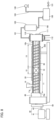
- Fig. 1 is a schematic diagram of the thermal decomposition system according to the first embodiment.
- the thermal decomposition system according to the first embodiment includes an extruder 100, a residue tank 110, a cooler 120, a receiver tank 130, and a suction apparatus 140.
- the thermal decomposition system according to the first embodiment further includes a cooler 150 and a receiver tank 160.
- the thermal decomposition system according to the first embodiment further includes a conduit 181, a conduit 182, a conduit 183, a conduit 184, and a conduit 185.
- An arrow shown by a solid line in Fig. 1 shows a flow of a polymer and an arrow shown by a dotted line in Fig. 1 shows a flow of decomposition gas or a liquid monomer.
- Residue tank 110 is connected to extruder 100. Cooler 120 is connected to residue tank 110 through conduit 181. Receiver tank 130 is connected to cooler 120 through conduit 182 and connected to suction apparatus 140 through conduit 183.
- Cooler 150 is connected to a hopper 14 of extruder 100 through conduit 184.
- Receiver tank 160 is connected to cooler 150 through conduit 185.
- Fig. 2 is a schematic cross-sectional view of extruder 100 included in the thermal decomposition system according to the first embodiment.
- extruder 100 includes a cylinder 10, a heater 20, a screw 30, a motor 40, and a gearbox 50.
- Extruder 100 may further include a shaft sealing mechanism 60.
- Extruder 100 is an extruder for thermal decomposition of a polymer.
- Cylinder 10 includes an upstream end 10a and a downstream end 10b. Downstream end 10b is an end opposite to upstream end 10a. Downstream end 10b is connected to residue tank 110.
- Heater 20 is arranged on an outer circumferential surface of cylinder 10.
- Heater 20 is, for example, a cast-in heater, a cartridge heater, or the like. Heater 20 heats a polymer located in cylinder 10. Heater 20, however, is not limited to an electric heater such as the cast-in heater or the cartridge heater.
- the polymer in cylinder 10 may be heated by steam or oil. In this case, steam or oil heats the polymer in cylinder 10 as it passes through a jacket provided in cylinder 10.
- Screw 30 is arranged in cylinder 10.
- Screw 30 is, for example, twin screws. Screw 30 applies shear force to the polymer in cylinder 10 while it carries the polymer located in cylinder 10 from a side of upstream end 10a toward downstream end 10b.
- Cylinder 10 includes a carrier portion 11, a plasticization portion 12, and a thermal decomposition portion 13.
- Plasticization portion 12 is located closer to downstream end 10b relative to carrier portion 11.
- Thermal decomposition portion 13 is located closer to downstream end 10b relative to plasticization portion 12.
- Hopper 14 is attached to carrier portion 11.
- a polymer is injected into carrier portion 11 through hopper 14.
- the polymer injected into carrier portion 11 is carried to plasticization portion 12 as screw 30 rotates.
- the polymer include a polymethyl methacrylate resin, a poly-lactic acid resin, a polyethylene terephthalate resin, a polystyrene resin, a polyamide resin, and a polypropylene resin.
- the polymer is not limited thereto. The polymer should only thermally be decomposed into decomposition gas.
- the polymer located in plasticization portion 12 is plasticized by heat from heater 20 and shear force from screw 30.
- the polymer located in plasticization portion 12 is carried to thermal decomposition portion 13 as screw 30 rotates.
- the polymer located in thermal decomposition portion 13 is thermally decomposed by heat from heater 20 and shear force from screw 30.
- the thermally decomposed polymer is converted to decomposition gas.
- Shaft sealing mechanism 60 hermetically seals upstream end 10a while screw 30 is ready to operate.
- a mechanical seal is employed as shaft sealing mechanism 60.
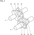
- Fig. 3 shows a first exemplary construction of screw 30.
- screw 30 includes a shaft 31 and a shaft 32 and a plurality of kneading discs 33a and a plurality of kneading discs 34a.
- Shaft 31 and shaft 32 extend in a direction identical to a direction of extension of cylinder 10. Shaft 31 and shaft 32 are rotated around the shaft core by gearbox 50.
- the plurality of kneading discs 33a are attached to shaft 31.
- the plurality of kneading discs 34a are attached to shaft 32.
- Kneading disc 33a closest to upstream end 10a is 180° out of phase with kneading disc 33a closest to downstream end 10b.
- the phase of kneading disc 33a varies toward downstream end 10b from the side of upstream end 10a.
- Variation in phase between two kneading discs 33a adjacent in the direction of extension of shaft 31 is equal to a value calculated by dividing 180° by a result of subtraction of one from the number of kneading discs 33a. Since there are five kneading discs 33a in the example in Fig. 3 , two adjacent kneading discs 33a are 45° out of phase with each other.
- Kneading disc 33a and kneading disc 34a adjacent to each other are 90° out of phase with each other.
- a direction of variation in phase of kneading discs 33a from the side of upstream end 10a toward downstream end 10b is identical to a direction of variation in phase of kneading discs 34a.
- screw 30 sends a polymer in a direction from upstream end 10a toward downstream end 10b while it applies shear force to the polymer.
- Fig. 4 shows a second exemplary construction of screw 30.
- the direction of variation in phase of two kneading discs 33a adjacent in the direction of extension of shaft 31 and the direction of variation in phase of two kneading discs 34a adjacent in the direction of extension of shaft 32 are reverse to the directions of variation in phase shown in Fig. 3 , respectively.
- the exemplary construction shown in Fig. 4 is otherwise common to the exemplary construction shown in Fig. 3 .
- screw 30 sends the polymer back in a direction from downstream end 10b toward upstream end 10a while it applies shear force to the polymer.
- Fig. 5 shows a third exemplary construction of screw 30.
- screw 30 may include a full flight screw 33b and a full flight screw 34b instead of the plurality of kneading discs 33a and the plurality of kneading discs 34a.
- Full flight screw 34b and full flight screw 33b are common in structure to each other.
- Full flight screw 33b is 90° out of phase with full flight screw 34b.
- screw 30 plays a role to mainly send the polymer in the direction from upstream end 10a toward downstream end 10b.
- Plasticization portion 12 is thus more readily filled with the polymer and shear force from screw 30 is more readily applied to the polymer located in plasticization portion 12. Consequently, plasticization of the polymer located in plasticization portion 12 more readily proceeds.
- thermal decomposition portion 13 For screw 30 located in thermal decomposition portion 13, for example, the exemplary construction shown in Fig. 3 , the exemplary construction shown in Fig. 4 , and the exemplary construction shown in Fig. 5 are used as being combined. Thermal decomposition portion 13 is thus more readily filled with the polymer and shear force from screw 30 is more readily applied to the polymer located in thermal decomposition portion 13. Consequently, thermal decomposition of the polymer located in thermal decomposition portion 13 more readily proceeds.
- screw 30 in plasticization portion 12 and thermal decomposition portion 13 is preferably in such a structure that plasticization portion 11 and thermal decomposition portion 13 are more readily filled with the polymer and shear force is more readily applied to the polymer.
- screw 30 in carrier portion 11 is preferably in such a structure that the polymer can smoothly be carried to plasticization portion 12.
- Fig. 6 is a cross-sectional view of hopper 14 included in extruder 100 of the thermal decomposition system according to the first embodiment.
- hopper 14 is cylindrical.
- Hopper 14 has a lower end attached to carrier portion 11.
- An internal space in hopper 14 and an internal space in carrier portion 11 (cylinder 10) are thus connected to each other through a hopper hole 11a.
- Hopper 14 has an upper end closed by a lid member 14a.
- An emission hole 14b is provided in a sidewall of hopper 14. Emission hole 14b passes through the sidewall of hopper 14. In other words, emission hole 14b is connected to the internal space in hopper 14. Conduit 184 is connected to emission hole 14b.
- a chute 14c is provided in the sidewall of hopper 14.
- a polymer is injected into hopper 14 through chute 14c.
- the polymer injected through chute 14c is injected into carrier portion 11 through hopper hole 11a provided in carrier portion 11.
- Chute 14c is provided with an introduction hole 14d.
- Inert gas is introduced into hopper 14 through introduction hole 14d.
- Inert gas is introduced into hopper 14 along an inner wall surface of the sidewall of hopper 14.
- Inert gas introduced into hopper 14 thus flows as swirling in hopper 14.
- nitrogen gas is adopted as inert gas.
- Fig. 7 is a flowchart showing a method of manufacturing decomposition gas with the use of the thermal decomposition system according to the first embodiment.
- the method of manufacturing decomposition gas with the use of the thermal decomposition system according to the first embodiment includes a polymer injection step S1, a polymer plasticization step S2, a polymer thermal decomposition step S3, and a monomer collection step S4.
- the method of manufacturing decomposition gas with the use of the thermal decomposition system according to the first embodiment further includes a decomposition gas emission step S5 and a monomer collection step S6.
- polymer injection step S1 a polymer is injected in extruder 100. More specifically, the polymer is injected into carrier portion 11 through hopper 14 and hopper hole 11a. The polymer injected into carrier portion 11 is carried to plasticization portion 12 as screw 30 rotates. The polymer injected in carrier portion 11 is heated by heater 20 while it is carried to plasticization portion 12 by screw 30.
- extruder 100 plasticizes the polymer.
- the polymer is plasticized in plasticization portion 12. More specifically, the polymer is plasticized by application of shear force by screw 30 and application of heat by heater 20 in plasticization portion 12.
- extruder 100 thermally decomposes at least some of the polymer plasticized in polymer plasticization step S2.
- the polymer is thermally decomposed in thermal decomposition portion 13. More specifically, the polymer is thermally decomposed by application of shear force by screw 30 and application of heat by heater 20 in decomposition portion 13. The thermally decomposed polymer is converted to decomposition gas. In polymer thermal decomposition step S3, the entire polymer does not have to thermally be decomposed.
- monomer collection step S4 a liquid monomer is collected.
- decomposition gas produced in polymer thermal decomposition step S3 is collected. More specifically, as suction apparatus 140 (for example, a vacuum pump) is driven, a pressure in the inside of residue tank 110, the inside of cooler 120, and the inside of receiver tank 130 becomes negative relative to the pressure in cylinder 10. Consequently, decomposition gas is sent from downstream end 10b through residue tank 110 to cooler 120. Since the negative pressure is produced in cooler 120 by variation in volume at the time of condensation of decomposition gas in cooler 120, decomposition gas can be sent to cooler 120 without using suction apparatus 140.
- suction apparatus 140 for example, a vacuum pump
- Decomposition gas sent to cooler 120 is then cooled in cooler 120. Cooling is performed, for example, by water cooling. More specifically, decomposition gas sent to cooler 120 passes through a cooling pipe arranged in cooler 120. Since water flows around the cooling pipe, decomposition gas sent to cooler 120 is condensed by cooling to become a liquid (liquid monomer). The liquid monomer condensed in cooler 120 is stored in receiver tank 130 and collected.
- the liquid monomer is taken out of receiver tank 130 through an outlet 131 (see Fig. 2 ) provided in an outer wall of receiver tank 130.
- the collected liquid monomer can be recycled as a polymer through a polymerization step.
- decomposition gas may be produced as a result of thermal decomposition of some of the polymer in plasticization portion 12.
- Decomposition gas may be produced as a result of thermal decomposition of some of the polymer in carrier portion 11, plasticization portion 12, and thermal decomposition portion 13 also while extruder 100 is at a standstill.
- Some of decomposition gas may flow back in cylinder 10 in the direction from downstream end 10b toward upstream end 10a. Decomposition gas that flows back may be referred to as backflow decomposition gas.
- backflow decomposition gas is emitted through emission hole 14b. More specifically, backflow decomposition gas that flows back to carrier portion 11 is suctioned into hopper 14 due to a cyclone phenomenon caused by swirl in hopper 14 of inert gas introduced through introduction hole 14d, and emitted through emission hole 14b.
- backflow decomposition gas emitted through emission hole 14b is sent to cooler 150 through conduit 184.
- backflow decomposition gas sent to cooler 150 is cooled in cooler 150. Cooling is performed, for example, by water cooling. More specifically, backflow decomposition gas sent to cooler 150 passes through a cooling pipe arranged in cooler 150. Since water flows around the cooling pipe, backflow decomposition gas sent to cooler 150 is condensed as it passes through the cooling pipe to become a liquid (liquid monomer). The liquid monomer condensed in cooler 150 is stored in receiver tank 160 through conduit 185.
- receiver tank 160 Thirdly, the liquid monomer stored in receiver tank 160 is collected.
- the liquid monomer is taken out of receiver tank 160 through an outlet 161 (see Fig. 2 ) provided in an outer wall of receiver tank 160.
- the polymer not thermally decomposed in polymer thermal decomposition step S3 and an impurity (a residue) contained in the polymer are discharged from downstream end 10b and stored in residue tank 110.
- a heater 111 (see Fig. 2 ) may be attached to an outer wall of residue tank 110. As heater 111 is activated, cooling of decomposition gas at an outdoor temperature and resultant condensation thereof in residue tank 110 is suppressed.
- the residue stored in residue tank 110 is taken out through an outlet 112 (see Fig. 2 ) provided in the outer wall of residue tank 110.
- a thermal decomposition system according to the comparative example includes an extruder 200 instead of extruder 100.
- Fig. 8 is a schematic cross-sectional view of extruder 200. As shown in Fig. 8 , the thermal decomposition system according to the comparative example does not include cooler 150 and receiver tank 160. In addition, the thermal decomposition system according to the comparative example does not include conduit 184 and conduit 185.
- Fig. 9 is a cross-sectional view of hopper 14 included in extruder 200. As shown in Fig. 9 , in extruder 200, hopper 14 does not have the upper end closed by lid member 14a. In addition, in extruder 200, emission hole 14b, chute 14c, and introduction hole 14d are not provided in the sidewall of hopper 14. Except for these aspects, the thermal decomposition system according to the comparative example is identical to the thermal decomposition system according to the first embodiment.
- decomposition gas produced in cylinder 10 may become backflow decomposition gas. Since the upper end of hopper 14 is not closed in the thermal decomposition system according to the comparative example, backflow decomposition gas may be emitted from the upper end of hopper 14 to the outside of the system.
- emission hole 14b is provided in hopper 14 and the upper end of hopper 14 is closed. Since inert gas is supplied through introduction hole 14d in the thermal decomposition system according to the first embodiment, backflow decomposition gas does not flow into chute 14c. Therefore, backflow decomposition gas is emitted through emission hole 14b. Backflow decomposition gas emitted through emission hole 14b is condensed in cooler 150 and stored in receiver tank 160. Therefore, emission of backflow decomposition gas to the outside of the system is suppressed.
- a temperature of backflow decomposition gas may be high (for example, at a temperature equal to or higher than a flash point or a spontaneous ignition point of backflow decomposition gas).
- the temperature of backflow decomposition gas may be equal to or higher than 400°C. Since backflow decomposition gas is cooled and then stored in the thermal decomposition system according to the embodiment, safety in treatment of backflow decomposition gas can be enhanced.
- a thermal decomposition system according to a second embodiment will be described. Differences from the thermal decomposition system according to the first embodiment will mainly be described and redundant description will not be repeated.
- Fig. 10 is a schematic diagram of the thermal decomposition system according to the second embodiment. As shown in Fig. 10 , the thermal decomposition system according to the second embodiment includes extruder 100, residue tank 110, cooler 120, receiver tank 130, and suction apparatus 140.
- the thermal decomposition system according to the second embodiment further includes cooler 150, receiver tank 160, and a suction apparatus 170.
- the thermal decomposition system according to the second embodiment further includes conduit 181, conduit 182, conduit 183, conduit 184, conduit 185, and a conduit 186.
- Suction apparatus 170 is connected to receiver tank 160 through conduit 186.
- a vacuum pump is employed as suction apparatus 170.
- Suction apparatus 170 is not limited thereto.
- An arrow shown by a solid line in Fig. 10 shows a flow of a polymer and an arrow shown by a dotted line in Fig. 10 shows a flow of decomposition gas or a liquid monomer.
- Fig. 11 is a cross-sectional view of hopper 14 included in extruder 100 of the thermal decomposition system according to the second embodiment.
- introduction hole 14d is not provided in chute 14c. Since the inside of hopper 14 is purged with inert gas, introduction hole 14d may be provided in the sidewall of hopper 14 in the thermal decomposition system according to the second embodiment.
- a thermal decomposition system according to a third embodiment will be described. Differences from the thermal decomposition system according to the first embodiment will mainly be described and redundant description will not be repeated.
- Fig. 12 is a schematic diagram of the thermal decomposition system according to the third embodiment. As shown in Fig. 12 , the thermal decomposition system according to the third embodiment includes extruder 100, residue tank 110, cooler 120, receiver tank 130, and suction apparatus 140.
- the thermal decomposition system according to the third embodiment further includes cooler 150, receiver tank 160, and a receiver tank 162.
- the thermal decomposition system according to the third embodiment further includes conduit 181, conduit 182, conduit 183, conduit 184, conduit 185, and a conduit 187.
- Hopper 14 of extruder 100 and receiver tank 162 are connected to each other through conduit 187.
- An arrow shown by a solid line in Fig. 12 shows a flow of a polymer and an arrow shown by a dotted line in Fig. 12 shows a flow of decomposition gas or a liquid monomer.
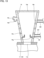
- Fig. 13 is a cross-sectional view of hopper 14 included in extruder 100 of the thermal decomposition system according to the third embodiment.
- a flow channel 14e is provided in the sidewall of hopper 14. Coolant flows through flow channel 14e. The sidewall of hopper 14 is thus cooled. Backflow decomposition gas in hopper 14 is condensed in the sidewall of hopper 14 to become a liquid monomer.
- an emission hole 14f is provided in the sidewall of hopper 14.
- Emission hole 14f passes through the sidewall of hopper 14.
- emission hole 14f is connected to the internal space in hopper 14.
- Conduit 187 is connected to emission hole 14f.
- the liquid monomer condensed in the sidewall of hopper 14 passes through emission hole 14f and conduit 187 and is stored in receiver tank 162. Therefore, emission of backflow decomposition gas to the outside of the system is suppressed also in the thermal decomposition system according to the third embodiment.
- a receiver 14g that receives a liquid polymer condensed in the sidewall of hopper 14 is provided in the sidewall of hopper 14.
- a thermal decomposition system according to a fourth embodiment will be described. Differences from the thermal decomposition system according to the first embodiment will mainly be described and redundant description will not be repeated.
- Fig. 14 is a schematic diagram of the thermal decomposition system according to the fourth embodiment.
- the thermal decomposition system according to the fourth embodiment includes extruder 100, residue tank 110, cooler 120, receiver tank 130, and suction apparatus 140.
- the thermal decomposition system according to the fourth embodiment further includes conduit 181, conduit 182, and conduit 183.
- the thermal decomposition system according to the fourth embodiment does not include cooler 150 and receiver tank 160.
- the thermal decomposition system according to the fourth embodiment does not include conduit 184 and conduit 185.
- An arrow shown by a solid line in Fig. 14 shows a flow of a polymer and an arrow shown by a dotted line in Fig. 14 shows a flow of decomposition gas or a liquid monomer.
- the thermal decomposition system according to the fourth embodiment may include cooler 150, receiver tank 160, conduit 184, and conduit 185.
- Fig. 15 is a cross-sectional view of hopper 14 included in extruder 100 of the thermal decomposition system according to the fourth embodiment.
- hopper 14 does not have the upper end closed by lid member 14a.
- the upper end of hopper 14 may partially be closed.
- emission hole 14b, chute 14c, and introduction hole 14d are not provided in the sidewall of hopper 14.
- emission hole 14c, chute 14c, and introduction hole 14d may be provided in the sidewall of hopper 14.
- extruder 100 includes an opening and closing apparatus 70.
- a gate valve serves as opening and closing apparatus 70.
- Opening and closing apparatus 70 includes a main body portion 71 and a partition plate 72.
- Main body portion 71 is provided with a through hole 71a.
- Opening and closing apparatus 70 can switch between a state in which through hole 71a is closed by partition plate 72 and a state in which through hole 71a is not closed by partition plate 72, by slide of partition plate 72.
- plasticization portion 12 While extruder 100 is operating, plasticization portion 12 is filled with a polymer and backflow decomposition gas is less likely to return to carrier portion 11. Decomposition of the polymer, however, proceeds even when extruder 100 is in a standstill. Therefore, the polymer filled in plasticization portion 12 no longer spatially isolates carrier portion 11 and thermal decomposition portion 13 from each other and backflow decomposition gas tends to return to carrier portion 11. Backflow decomposition gas that returns to carrier portion 11 may be emitted to the outside of the system through hopper 14.
- opening and closing apparatus 70 cuts off the internal space in hopper 14 from the space on the outside of hopper 14 while extruder 100 is in a standstill. Therefore, emission of backflow decomposition gas to the outside of the system is suppressed.
- the thermal decomposition system according to the fourth embodiment since the internal space in hopper 14 is connected to the space on the outside of hopper 14 while extruder 100 is operating, injection of a polymer into carrier portion 11 through hopper 14 is not interfered.
- a thermal decomposition system according to a fifth embodiment will be described. Differences from the thermal decomposition system according to the first embodiment will mainly be described and redundant description will not be repeated.
- Fig. 16 is a schematic diagram of the thermal decomposition system according to the fifth embodiment.
- the thermal decomposition system according to the fifth embodiment includes extruder 100, residue tank 110, cooler 120, receiver tank 130, and suction apparatus 140.
- the thermal decomposition system according to the fifth embodiment further includes conduit 181, conduit 182, and conduit 183.
- the thermal decomposition system according to the fifth embodiment does not include cooler 150 and receiver tank 160.
- the thermal decomposition system according to the fifth embodiment does not include conduit 184 and conduit 185.
- the thermal decomposition system according to the fifth embodiment includes a receiver tank 163 and a conduit 188. Extruder 100 and receiver tank 163 are connected to each other through conduit 188.
- An arrow shown by a solid line in Fig. 16 shows a flow of a polymer and an arrow shown by a dotted line in Fig. 16 shows a flow of decomposition gas or a liquid monomer.
- the thermal decomposition system according to the fifth embodiment may include cooler 150, receiver tank 160, conduit 184, and conduit 185.
- Fig. 17 is a cross-sectional view of cylinder 10 included in extruder 100 of the thermal decomposition system according to the fifth embodiment.
- cylinder 10 is composed of a plurality of divided cylinders 15 aligned along the direction from upstream end 10a toward downstream end 10b.
- Each of divided cylinders 15 is provided with a flow channel 16. Coolant flows through flow channel 16.
- coolant can independently flow through flow channel 16 in each of divided cylinders 15.
- flow channel 16 is preferably provided in divided cylinder 15 that makes up thermal decomposition portion 13, flow channel 16 does not have to be provided in divided cylinder 15 that makes up thermal decomposition portion 13.
- Coolant does not flow through flow channel 16 in divided cylinder 15 that makes up carrier portion 11 while extruder 100 is operating (that is, screw 30 is operating), whereas coolant flows therethrough while extruder 100 is in a standstill (that is, while screw 30 is in a standstill). Coolant, however, may constantly flow through flow channel 16 provided in divided cylinder 15 provided with hopper hole 11a.
- Coolant does not flow through flow channel 16 in divided cylinder 15 that makes up plasticization portion 12 while extruder 100 is operating, whereas coolant flows therethrough while extruder 100 is in a standstill. Coolant does not flow through flow channel 16 in divided cylinder 15 that makes up thermal decomposition portion 13 while extruder 100 is operating, whereas coolant flows therethrough while extruder 100 is in a standstill. Coolant does not have to flow through flow channel 16 in divided cylinder 15 that makes up thermal decomposition portion 13 while extruder 100 is in a standstill.
- divided cylinder 15 provided with hopper hole 11a is provided with a slit 11b.
- Slit 11b passes through divided cylinder 15 and connects an internal space in divided cylinder 15 and a space on the outside of divided cylinder 15 to each other.
- Slit 11b is connected to conduit 188.
- Slit 11b is provided in a lower portion of divided cylinder 15 provided with hopper hole 11a.
- Divided cylinder 15 provided with hopper hole 11a may be provided with a mesh instead of slit 11b.
- Divided cylinder 15 that makes up carrier portion 11 other than divided cylinder 15 provided with hopper hole 11a may be provided with slit 11b (mesh).
- Slit 11b (mesh) may be provided in a portion other than the lower portion of divided cylinder 15.
- heater 20 While screw 30 is in a standstill, heater 20 is not activated (heating of the polymer is stopped).
- thermal decomposition of the polymer in carrier portion 11 and plasticization portion 12 may proceed and backflow decomposition gas may be produced.
- carrier portion 11 and plasticization portion 12 are cooled while extruder 100 is in a standstill. Therefore, backflow decomposition gas resulting from thermal decomposition of the polymer in carrier portion 11 and plasticization portion 12 is condensed in carrier portion 11 and plasticization portion 12 to become a liquid polymer. This liquid polymer passes through slit 11b and conduit 188 and is stored in receiver tank 163. Therefore, in the thermal decomposition system according to the fifth embodiment, emission of backflow decomposition gas produced in carrier portion 11 and plasticization portion 12 to the outside of the system is suppressed.
Landscapes
- Engineering & Computer Science (AREA)
- Mechanical Engineering (AREA)
- Chemical & Material Sciences (AREA)
- Polymers & Plastics (AREA)
- Health & Medical Sciences (AREA)
- Sustainable Development (AREA)
- Chemical Kinetics & Catalysis (AREA)
- Medicinal Chemistry (AREA)
- Life Sciences & Earth Sciences (AREA)
- Organic Chemistry (AREA)
- Physics & Mathematics (AREA)
- Thermal Sciences (AREA)
- Environmental & Geological Engineering (AREA)
- Separation, Recovery Or Treatment Of Waste Materials Containing Plastics (AREA)
- Processing And Handling Of Plastics And Other Materials For Molding In General (AREA)
- Production Of Liquid Hydrocarbon Mixture For Refining Petroleum (AREA)
Applications Claiming Priority (2)
| Application Number | Priority Date | Filing Date | Title |
|---|---|---|---|
| JP2021025439A JP7709834B2 (ja) | 2021-02-19 | 2021-02-19 | 熱分解用押出機、分解ガスの製造方法及び排出方法 |
| PCT/JP2021/045362 WO2022176340A1 (ja) | 2021-02-19 | 2021-12-09 | 熱分解用押出機、熱分解システム、分解ガスの製造方法及び排出方法 |
Publications (2)
| Publication Number | Publication Date |
|---|---|
| EP4296301A1 true EP4296301A1 (de) | 2023-12-27 |
| EP4296301A4 EP4296301A4 (de) | 2025-02-26 |
Family
ID=82930585
Family Applications (1)
| Application Number | Title | Priority Date | Filing Date |
|---|---|---|---|
| EP21926765.5A Pending EP4296301A4 (de) | 2021-02-19 | 2021-12-09 | Extruder für thermische zersetzung, system für thermische zersetzung, herstellungsverfahren und entladungsverfahren für zersetzungsgas |
Country Status (6)
| Country | Link |
|---|---|
| US (1) | US20240076466A1 (de) |
| EP (1) | EP4296301A4 (de) |
| JP (1) | JP7709834B2 (de) |
| KR (1) | KR102871070B1 (de) |
| CN (1) | CN116867850A (de) |
| WO (1) | WO2022176340A1 (de) |
Families Citing this family (2)
| Publication number | Priority date | Publication date | Assignee | Title |
|---|---|---|---|---|
| JP2024022995A (ja) * | 2022-08-08 | 2024-02-21 | 株式会社日本製鋼所 | 樹脂の分解処理方法および分解処理装置 |
| JPWO2024105826A1 (de) | 2022-11-16 | 2024-05-23 |
Family Cites Families (22)
| Publication number | Priority date | Publication date | Assignee | Title |
|---|---|---|---|---|
| DE2623823A1 (de) * | 1976-05-28 | 1977-12-08 | Sapco Systemanalyse & Projektb | Vorrichtung zur zufuehrung von granulat- oder pulverfoermigen kunststoffen unter vakuum |
| JPS55121026A (en) * | 1979-03-12 | 1980-09-17 | Koichi Nagata | Grinding, heating and fusing device for bulky expanded styrol resin |
| US5708133A (en) * | 1993-11-09 | 1998-01-13 | Mitsubishi Gas Chemical Company, Inc. | Process for purifying polymer |
| JP2530417B2 (ja) * | 1993-11-10 | 1996-09-04 | 株式会社佐藤鉄工所 | 真空練り出し成形方法とその装置 |
| JPH0971784A (ja) * | 1995-09-07 | 1997-03-18 | Mitsui Petrochem Ind Ltd | 廃プラスチックの油化方法 |
| JPH09254157A (ja) * | 1996-03-22 | 1997-09-30 | Tajiri:Kk | 廃棄プラスチック等の減容機 |
| CN1234761A (zh) * | 1997-07-18 | 1999-11-10 | 师桥洋 | 塑料材料等的成形方法及其装置 |
| JP3410343B2 (ja) | 1997-10-08 | 2003-05-26 | 高水化学工業株式会社 | アクリル樹脂の連続再生方法およびその装置 |
| JPH11291289A (ja) * | 1998-04-10 | 1999-10-26 | Canon Inc | 射出成形方法およびその装置 |
| JP2000000822A (ja) | 1998-06-17 | 2000-01-07 | Toshiba Corp | 廃棄物処理方法と廃棄物処理装置 |
| JP2001179779A (ja) | 1999-12-24 | 2001-07-03 | Meiki Co Ltd | ガス溶解樹脂の射出装置および射出成形方法 |
| JP2002067085A (ja) | 2000-08-28 | 2002-03-05 | Mitsubishi Heavy Ind Ltd | 射出装置の連続供給機構 |
| JP2002307530A (ja) * | 2001-04-09 | 2002-10-23 | Japan Steel Works Ltd:The | 押出機を用いる脱揮方法及びその装置 |
| JP2003056822A (ja) | 2001-08-16 | 2003-02-26 | Ebara Corp | 流動層ガス化炉の可燃物供給方法及び可燃物供給装置 |
| JP2005263980A (ja) | 2004-03-18 | 2005-09-29 | Honda Motor Co Ltd | 廃棄物の処理方法及び処理装置 |
| JP4325542B2 (ja) | 2004-11-17 | 2009-09-02 | 日立電線株式会社 | 高分子化合物の処理方法及びその装置 |
| JP5138183B2 (ja) | 2005-06-14 | 2013-02-06 | 東芝機械株式会社 | 射出成形方法および射出成形機 |
| JP2007290200A (ja) | 2006-04-24 | 2007-11-08 | Meino:Kk | 廃棄発泡スチロールのペレット化装置 |
| JP2009084311A (ja) * | 2007-09-27 | 2009-04-23 | Fujifilm Corp | 環状オレフィン系樹脂フィルムの製造方法、環状オレフィン系樹脂フィルム,偏光版、液晶表示板用光学補償フィルム及び反射防止フィルム |
| JP2009113360A (ja) | 2007-11-07 | 2009-05-28 | Yamatake Corp | 射出成型機用プランジャ式射出シリンダ |
| JP2011236337A (ja) | 2010-05-11 | 2011-11-24 | Mitsubishi Rayon Co Ltd | 樹脂の熱分解装置および熱分解方法 |
| DE102015001167A1 (de) * | 2015-02-02 | 2016-08-04 | Entex Rust & Mitschke Gmbh | Entgasen bei der Extrusion von Kunststoffen |
-
2021
- 2021-02-19 JP JP2021025439A patent/JP7709834B2/ja active Active
- 2021-12-09 CN CN202180094171.3A patent/CN116867850A/zh active Pending
- 2021-12-09 KR KR1020237031149A patent/KR102871070B1/ko active Active
- 2021-12-09 EP EP21926765.5A patent/EP4296301A4/de active Pending
- 2021-12-09 US US18/272,588 patent/US20240076466A1/en active Pending
- 2021-12-09 WO PCT/JP2021/045362 patent/WO2022176340A1/ja not_active Ceased
Also Published As
| Publication number | Publication date |
|---|---|
| EP4296301A4 (de) | 2025-02-26 |
| US20240076466A1 (en) | 2024-03-07 |
| JP2022127346A (ja) | 2022-08-31 |
| CN116867850A (zh) | 2023-10-10 |
| KR20230146577A (ko) | 2023-10-19 |
| KR102871070B1 (ko) | 2025-10-15 |
| WO2022176340A1 (ja) | 2022-08-25 |
| JP7709834B2 (ja) | 2025-07-17 |
Similar Documents
| Publication | Publication Date | Title |
|---|---|---|
| EP4296301A1 (de) | Extruder für thermische zersetzung, system für thermische zersetzung, herstellungsverfahren und entladungsverfahren für zersetzungsgas | |
| US7960491B2 (en) | Isoolefin-diolefin production process and apparatus therefore | |
| US9108354B2 (en) | Process for de-airing material in an extruder that includes a vent block | |
| JP2010126490A (ja) | ラクチド回収装置および回収方法 | |
| JP4325542B2 (ja) | 高分子化合物の処理方法及びその装置 | |
| JP5208697B2 (ja) | ラクチド回収装置および回収方法 | |
| CN1332733C (zh) | 抽取装置 | |
| JP7639215B1 (ja) | 熱分解装置 | |
| JP3895103B2 (ja) | 廃棄プラスチックの脱塩素処理装置 | |
| EP1550536B1 (de) | Verfahren zum recyceln von geschäumtem polystyrolharz | |
| US20180001514A1 (en) | Extruder provided with vents | |
| JP4737162B2 (ja) | 薬剤の液化回収方法及び薬剤の液化回収装置 | |
| JP5544664B2 (ja) | 熱硬化性樹脂の分解処理装置および該樹脂の分解処理方法 | |
| JP2013053210A (ja) | 熱硬化性樹脂の分解処理装置および該樹脂の分解処理方法 | |
| JP2007084748A (ja) | 高分子化合物と薬剤の回収方法及び装置 | |
| EP4600293A1 (de) | Pyrolysesystem und abfallkunststoffpyrolysesystem | |
| US20260042894A1 (en) | Resin decomposition treatment method and decomposition treatment device | |
| US20230415380A1 (en) | Die plate cover, die head, extruder, and method of manufacturing resin pellets | |
| KR100610289B1 (ko) | 고분자 화합물의 처리 방법 및 처리 장치 | |
| US20240360365A1 (en) | Waste plastic oilification reduction system | |
| WO2024157483A1 (ja) | 樹脂材料の熱分解処理方法、樹脂材料の熱分解処理システムおよびベント装置 | |
| JP2009051868A (ja) | 高分子化合物の処理方法及びその装置 | |
| JP2006009033A (ja) | 抽出装置 | |
| JP2005330365A (ja) | 高分子化合物の処理方法及びその装置 | |
| JP2007106827A (ja) | 高分子化合物の処理方法 |
Legal Events
| Date | Code | Title | Description |
|---|---|---|---|
| STAA | Information on the status of an ep patent application or granted ep patent |
Free format text: STATUS: THE INTERNATIONAL PUBLICATION HAS BEEN MADE |
|
| PUAI | Public reference made under article 153(3) epc to a published international application that has entered the european phase |
Free format text: ORIGINAL CODE: 0009012 |
|
| STAA | Information on the status of an ep patent application or granted ep patent |
Free format text: STATUS: REQUEST FOR EXAMINATION WAS MADE |
|
| 17P | Request for examination filed |
Effective date: 20230918 |
|
| AK | Designated contracting states |
Kind code of ref document: A1 Designated state(s): AL AT BE BG CH CY CZ DE DK EE ES FI FR GB GR HR HU IE IS IT LI LT LU LV MC MK MT NL NO PL PT RO RS SE SI SK SM TR |
|
| DAV | Request for validation of the european patent (deleted) | ||
| DAX | Request for extension of the european patent (deleted) | ||
| REG | Reference to a national code |
Ref country code: DE Ref legal event code: R079 Free format text: PREVIOUS MAIN CLASS: C08J0011060000 Ipc: B29B0007840000 |
|
| A4 | Supplementary search report drawn up and despatched |
Effective date: 20250128 |
|
| RIC1 | Information provided on ipc code assigned before grant |
Ipc: B29B 7/82 20060101ALN20250122BHEP Ipc: B29C 48/275 20190101ALN20250122BHEP Ipc: B29B 7/86 20060101ALN20250122BHEP Ipc: B29C 48/50 20190101ALI20250122BHEP Ipc: C08J 11/06 20060101ALI20250122BHEP Ipc: B29C 48/29 20190101ALI20250122BHEP Ipc: B29C 48/76 20190101ALI20250122BHEP Ipc: B29B 7/48 20060101ALI20250122BHEP Ipc: B29B 7/84 20060101AFI20250122BHEP |