EP4265568A2 - Prozess zur herstellung einer sekundärbatterie - Google Patents
Prozess zur herstellung einer sekundärbatterie Download PDFInfo
- Publication number
- EP4265568A2 EP4265568A2 EP23195533.7A EP23195533A EP4265568A2 EP 4265568 A2 EP4265568 A2 EP 4265568A2 EP 23195533 A EP23195533 A EP 23195533A EP 4265568 A2 EP4265568 A2 EP 4265568A2
- Authority
- EP
- European Patent Office
- Prior art keywords
- active material
- optionally
- particle size
- negative
- negative active
- Prior art date
- Legal status (The legal status is an assumption and is not a legal conclusion. Google has not performed a legal analysis and makes no representation as to the accuracy of the status listed.)
- Pending
Links
Images

Classifications
-
- H—ELECTRICITY
- H01—ELECTRIC ELEMENTS
- H01M—PROCESSES OR MEANS, e.g. BATTERIES, FOR THE DIRECT CONVERSION OF CHEMICAL ENERGY INTO ELECTRICAL ENERGY
- H01M10/00—Secondary cells; Manufacture thereof
- H01M10/05—Accumulators with non-aqueous electrolyte
- H01M10/052—Li-accumulators
- H01M10/0525—Rocking-chair batteries, i.e. batteries with lithium insertion or intercalation in both electrodes; Lithium-ion batteries
-
- C—CHEMISTRY; METALLURGY
- C01—INORGANIC CHEMISTRY
- C01B—NON-METALLIC ELEMENTS; COMPOUNDS THEREOF; METALLOIDS OR COMPOUNDS THEREOF NOT COVERED BY SUBCLASS C01C
- C01B32/00—Carbon; Compounds thereof
- C01B32/20—Graphite
- C01B32/205—Preparation
-
- H—ELECTRICITY
- H01—ELECTRIC ELEMENTS
- H01M—PROCESSES OR MEANS, e.g. BATTERIES, FOR THE DIRECT CONVERSION OF CHEMICAL ENERGY INTO ELECTRICAL ENERGY
- H01M10/00—Secondary cells; Manufacture thereof
- H01M10/05—Accumulators with non-aqueous electrolyte
- H01M10/058—Construction or manufacture
- H01M10/0585—Construction or manufacture of accumulators having only flat construction elements, i.e. flat positive electrodes, flat negative electrodes and flat separators
-
- H—ELECTRICITY
- H01—ELECTRIC ELEMENTS
- H01M—PROCESSES OR MEANS, e.g. BATTERIES, FOR THE DIRECT CONVERSION OF CHEMICAL ENERGY INTO ELECTRICAL ENERGY
- H01M4/00—Electrodes
- H01M4/02—Electrodes composed of, or comprising, active material
- H01M4/13—Electrodes for accumulators with non-aqueous electrolyte, e.g. for lithium-accumulators; Processes of manufacture thereof
- H01M4/131—Electrodes based on mixed oxides or hydroxides, or on mixtures of oxides or hydroxides, e.g. LiCoOx
-
- H—ELECTRICITY
- H01—ELECTRIC ELEMENTS
- H01M—PROCESSES OR MEANS, e.g. BATTERIES, FOR THE DIRECT CONVERSION OF CHEMICAL ENERGY INTO ELECTRICAL ENERGY
- H01M4/00—Electrodes
- H01M4/02—Electrodes composed of, or comprising, active material
- H01M4/13—Electrodes for accumulators with non-aqueous electrolyte, e.g. for lithium-accumulators; Processes of manufacture thereof
- H01M4/133—Electrodes based on carbonaceous material, e.g. graphite-intercalation compounds or CFx
-
- H—ELECTRICITY
- H01—ELECTRIC ELEMENTS
- H01M—PROCESSES OR MEANS, e.g. BATTERIES, FOR THE DIRECT CONVERSION OF CHEMICAL ENERGY INTO ELECTRICAL ENERGY
- H01M4/00—Electrodes
- H01M4/02—Electrodes composed of, or comprising, active material
- H01M4/13—Electrodes for accumulators with non-aqueous electrolyte, e.g. for lithium-accumulators; Processes of manufacture thereof
- H01M4/139—Processes of manufacture
- H01M4/1393—Processes of manufacture of electrodes based on carbonaceous material, e.g. graphite-intercalation compounds or CFx
-
- H—ELECTRICITY
- H01—ELECTRIC ELEMENTS
- H01M—PROCESSES OR MEANS, e.g. BATTERIES, FOR THE DIRECT CONVERSION OF CHEMICAL ENERGY INTO ELECTRICAL ENERGY
- H01M4/00—Electrodes
- H01M4/02—Electrodes composed of, or comprising, active material
- H01M4/36—Selection of substances as active materials, active masses, active liquids
- H01M4/362—Composites
- H01M4/364—Composites as mixtures
-
- H—ELECTRICITY
- H01—ELECTRIC ELEMENTS
- H01M—PROCESSES OR MEANS, e.g. BATTERIES, FOR THE DIRECT CONVERSION OF CHEMICAL ENERGY INTO ELECTRICAL ENERGY
- H01M4/00—Electrodes
- H01M4/02—Electrodes composed of, or comprising, active material
- H01M4/36—Selection of substances as active materials, active masses, active liquids
- H01M4/362—Composites
- H01M4/366—Composites as layered products
-
- H—ELECTRICITY
- H01—ELECTRIC ELEMENTS
- H01M—PROCESSES OR MEANS, e.g. BATTERIES, FOR THE DIRECT CONVERSION OF CHEMICAL ENERGY INTO ELECTRICAL ENERGY
- H01M4/00—Electrodes
- H01M4/02—Electrodes composed of, or comprising, active material
- H01M4/36—Selection of substances as active materials, active masses, active liquids
- H01M4/48—Selection of substances as active materials, active masses, active liquids of inorganic oxides or hydroxides
- H01M4/52—Selection of substances as active materials, active masses, active liquids of inorganic oxides or hydroxides of nickel, cobalt or iron
- H01M4/525—Selection of substances as active materials, active masses, active liquids of inorganic oxides or hydroxides of nickel, cobalt or iron of mixed oxides or hydroxides containing iron, cobalt or nickel for inserting or intercalating light metals, e.g. LiNiO2, LiCoO2 or LiCoOxFy
-
- H—ELECTRICITY
- H01—ELECTRIC ELEMENTS
- H01M—PROCESSES OR MEANS, e.g. BATTERIES, FOR THE DIRECT CONVERSION OF CHEMICAL ENERGY INTO ELECTRICAL ENERGY
- H01M4/00—Electrodes
- H01M4/02—Electrodes composed of, or comprising, active material
- H01M4/36—Selection of substances as active materials, active masses, active liquids
- H01M4/58—Selection of substances as active materials, active masses, active liquids of inorganic compounds other than oxides or hydroxides, e.g. sulfides, selenides, tellurides, halogenides or LiCoFy; of polyanionic structures, e.g. phosphates, silicates or borates
- H01M4/583—Carbonaceous material, e.g. graphite-intercalation compounds or CFx
- H01M4/587—Carbonaceous material, e.g. graphite-intercalation compounds or CFx for inserting or intercalating light metals
-
- H—ELECTRICITY
- H01—ELECTRIC ELEMENTS
- H01M—PROCESSES OR MEANS, e.g. BATTERIES, FOR THE DIRECT CONVERSION OF CHEMICAL ENERGY INTO ELECTRICAL ENERGY
- H01M4/00—Electrodes
- H01M4/02—Electrodes composed of, or comprising, active material
- H01M2004/021—Physical characteristics, e.g. porosity, surface area
-
- H—ELECTRICITY
- H01—ELECTRIC ELEMENTS
- H01M—PROCESSES OR MEANS, e.g. BATTERIES, FOR THE DIRECT CONVERSION OF CHEMICAL ENERGY INTO ELECTRICAL ENERGY
- H01M4/00—Electrodes
- H01M4/02—Electrodes composed of, or comprising, active material
- H01M2004/026—Electrodes composed of, or comprising, active material characterised by the polarity
- H01M2004/027—Negative electrodes
-
- Y—GENERAL TAGGING OF NEW TECHNOLOGICAL DEVELOPMENTS; GENERAL TAGGING OF CROSS-SECTIONAL TECHNOLOGIES SPANNING OVER SEVERAL SECTIONS OF THE IPC; TECHNICAL SUBJECTS COVERED BY FORMER USPC CROSS-REFERENCE ART COLLECTIONS [XRACs] AND DIGESTS
- Y02—TECHNOLOGIES OR APPLICATIONS FOR MITIGATION OR ADAPTATION AGAINST CLIMATE CHANGE
- Y02E—REDUCTION OF GREENHOUSE GAS [GHG] EMISSIONS, RELATED TO ENERGY GENERATION, TRANSMISSION OR DISTRIBUTION
- Y02E60/00—Enabling technologies; Technologies with a potential or indirect contribution to GHG emissions mitigation
- Y02E60/10—Energy storage using batteries
-
- Y—GENERAL TAGGING OF NEW TECHNOLOGICAL DEVELOPMENTS; GENERAL TAGGING OF CROSS-SECTIONAL TECHNOLOGIES SPANNING OVER SEVERAL SECTIONS OF THE IPC; TECHNICAL SUBJECTS COVERED BY FORMER USPC CROSS-REFERENCE ART COLLECTIONS [XRACs] AND DIGESTS
- Y02—TECHNOLOGIES OR APPLICATIONS FOR MITIGATION OR ADAPTATION AGAINST CLIMATE CHANGE
- Y02P—CLIMATE CHANGE MITIGATION TECHNOLOGIES IN THE PRODUCTION OR PROCESSING OF GOODS
- Y02P70/00—Climate change mitigation technologies in the production process for final industrial or consumer products
- Y02P70/50—Manufacturing or production processes characterised by the final manufactured product
Definitions
- the present application belongs to the technical field of secondary battery, and particularly, relates to a secondary battery and a battery module, pack and apparatus containing the secondary battery.
- Secondary batteries have the advantages of reliable working performance, non-pollution, no memory effect, etc., thus are widely used. For example, with the increasing attention to environmental protection issues and the increasing popularity of new energy vehicles, the demand for power secondary batteries will show its boom. Nevertheless, as the application range of secondary batteries becomes wider and wider, severe challenges would be confronted to the performance of secondary batteries. In order to improve the user experience, the secondary battery should have various performances such as dynamic performance, and at the same time have cycle life. The problem existed in the prior art is that when the dynamic performance of the batter is improved, it is usually difficult to simultaneously obtain cycle performance at high temperature of the battery.
- the present application is developed in view of the above technical problems, whose purpose is to provide a secondary battery that has improved dynamic performance and simultaneously has better cycle performance at high temperature and safety performance.
- the present application provides a secondary battery, including a positive plate and a negative plate, wherein the positive plate includes a positive current collector and a positive film arranged on at least one surface of the positive current collector and including a positive active material, the positive active material comprising one or more of layered lithium transition metal oxides and the modified compounds thereof, wherein the negative plate includes a negative current collector and a negative electrode film arranged on at least one surface of the negative current collector and including a negative active material, the negative active material comprising a first material and a second material, wherein the first material includes an artificial graphite and the second material includes a natural graphite; and wherein the artificial graphite includes primary particles and secondary particles both, and a number percentage S of the secondary particles in the negative active materials satisfies: 10% ⁇ S ⁇ 50%.
- the inventors of the present application after intensive research found that, when the positive active material comprises one or more of layered lithium transition metal oxides and the modified compounds thereof, when the negative active material of the negative electrode film of the secondary battery comprises a artificial graphite and a natural graphite, wherein the artificial graphite includes primary particles and secondary particles, and a number percentage S of the secondary particles in the negative active materials is set in specific range, the secondary battery could have improved dynamic performance , and simultaneously have cycle performance at high temperature.
- the number percentage S of the secondary particles in the negative active material may optionally satisfy: 10% ⁇ S ⁇ 30%, and more optionally 15% ⁇ S ⁇ 30%. By setting the number percentage S of the secondary particles in the negative active material within the above range, the dynamic performance and cycle performance at high temperature of the battery can be further improved.
- the volume average particle size D v 50 of the negative active material is less than or equal to 14.0 ⁇ m; optionally, the volume average particle size D v 50 of the negative active material is from 8.0 ⁇ m to 12.0 ⁇ m; optionally, the volume average particle size D v 50 of the negative active material is from 12.0 ⁇ m to 14.0 ⁇ m.
- the safety performance of the battery may be further improved.
- the volume average particle size D v 50 of the artificial graphite may be from 10.0 ⁇ m to 14.5 ⁇ m, optionally may be from 11.0 ⁇ m to 13.5 ⁇ m; and/or, the volume average particle size D v 50 of the natural graphite may be from 7.0 ⁇ m to 14.0 ⁇ m, and optionally may be from 7.0 ⁇ m to 13.0 ⁇ m.
- the volume particle size distribution D v 90 of the negative active material may be from 16.0 ⁇ m to 25.0 ⁇ m, and optionally may be from 20.0 ⁇ m to 25.0 ⁇ m.
- the battery can simultaneously have better dynamic performance, cycle performance at high temperature and safety performance.
- the volume particle size distribution D v 90 of the artificial graphite may be from 23.0 ⁇ m to 30.0 ⁇ m, optionally may be from 25.0 ⁇ m to 29.0 ⁇ m; and/or, the volume particle size distribution D v 90 of the natural graphite may be from 15.0 ⁇ m to 23.0 ⁇ m, and optionally may be from 18.0 ⁇ m to 21.0 ⁇ m.
- the volume particle size distribution D v 99 of the negative active material may be from 25.0 ⁇ m to 37.0 ⁇ m, and optionally may be from 33.0 ⁇ m to 36.5 ⁇ m.
- the battery can simultaneously have better dynamic performance, cycle performance at high temperature and safety performance.
- the volume particle size distribution D v 99 of the artificial graphite may be from 30.0 ⁇ m to 45.0 ⁇ m, optionally may be from 32.0 ⁇ m to 43.0 ⁇ m; and/or, the volume particle size distribution D v 99 of the natural graphite may be from 21.0 ⁇ m to 35.0 ⁇ m, optionally may be from 25.0 ⁇ m to 30.0 ⁇ m.
- the particle size distribution (D v 90-D v 10)/D v 50 of the negative active material may be from 1.30 to 1.55, and optionally may be from 1.35 to 1.50.
- the particle size distribution (D v 90-D v 10)/D v 50 of the negative active material falls within the above range, the battery can simultaneously have better dynamic performance, cycle performance at high temperature and safety performance.
- the particle size distribution (D v 90-D v 10)/D v 50 of the negative active material may be from 1.25 to 1.95, optionally may be from 1.35 to 1.80; and/or, the particle size distribution (D v 90-D v 10)/D v 50 of the natural graphite may be from 0.88 to 1.28, optionally may be from 0.98 to 1.18.
- the number percentage of the secondary particles in the artificial graphite may be from 25% to 60%, and optionally may be from 30% to 50%. When the number percentage of the secondary particles in the artificial graphite falls within the above range, the expansion rate of the plate can be further reduced.
- the tap density of the negative active material may satisfy ⁇ 1.10 g/cm 3 , and optionally may be from 1.10 g/cm 3 to1.15 g/cm 3 .
- the tap density of the negative active material falls within the above range, the energy density and dynamic performance of the battery can be further improved.
- the tap density of the artificial graphite may be from 0.90g/cm 3 to 1.20g/cm 3 , optionally may be from 1.15g/cm 3 to 1.15g/cm 3 ; and/or the tap density of the natural graphite may be from 0.90 g/cm 3 to 1.18g/cm 3 , and optional may be from 0.93g/cm 3 to 1.13g/cm 3 .
- the graphitization degree of the negative active material may be from 92% to 96%, and optionally may be from 93% to 95%.
- the energy density of the battery can be further increased and the expansion rate of the plate can be reduced.
- the graphitization degree of the artificial graphite may be from 90% to 95%, optionally may be from 93% to 95%; and/or, the graphitization degree of the natural graphite may be from 95% to 98%, and optionally may be from 95% to 97%.
- the natural graphite has a coating layer on its surface.
- a coating layer on the surface of the natural graphite, the surface activity of the natural graphite can be reduced, thereby further improving the cycle performance at high temperature of the battery.
- the mass percentage of the natural graphite in the negative active material may satisfy ⁇ 30%, optionally from 15% to 25%.
- the mass percentage of the natural graphite in the negative active material falls within the above range, it would attain higher energy density of the battery and significantly reduce side reactions during the battery cycle, thereby further improving the cycle performance at high temperature and safety performance of the battery.
- the compaction density of the negative electrode film may be from 1.60 g/cm 3 to 1.80 g/cm 3 , and optionally may be from 1.65 g/cm 3 to 1.75 g/cm 3 .
- the dynamic performance and energy density of the battery can be further improved.
- the areal density of the negative electrode film may be from 10.0 mg/cm 2 to 13.0 mg/cm 2 , and optionally may be from 10.5 mg/cm 2 to 11.5 mg/cm 2 .
- the areal density of the negative electrode film falls within the above range, the dynamic performance of the battery and the cycle performance of the battery can be further improved.
- the cohesion force F of the negative electrode film may satisfy: 220N/m ⁇ F ⁇ 300N/m, optionally 240N/m ⁇ F ⁇ 260N/m.
- the cohesion force of the negative electrode film falls within the above range, the negative electrode film could have higher active ions and electrons transportation performance, and at the same time, it could have reduced cycle expansion rate of the electrode plate and reduced the amount of binder added in the negative electrode film.
- the positive active material may comprise a layered lithium transition metal oxide having a general formula Li a Ni b Co c M d M' e O f A g , wherein 0.8 ⁇ a ⁇ 1.2, 0.6 ⁇ b ⁇ 1, 0 ⁇ c ⁇ 1, 0 ⁇ d ⁇ 1, 0 ⁇ e ⁇ 0.1, 1 ⁇ f ⁇ 2, and 0 ⁇ g ⁇ 1; M is one or more selected from the group consisting of Mn and Al; M' is one or more selected from Zr, Mn, Al, Zn, Cu, Cr, Mg, Fe, V, Ti and B; and A is one or more selected from N, F, S and Cl; and optionally, 0.65allyCu, en the above-mentioned materials are used as the positive active material, the improvement in the safety performance of the battery is more significant.
- M is one or more selected from the group consisting of Mn and Al
- M' is one or more selected from Zr, Mn, Al, Zn, Cu, Cr, Mg, Fe, V, Ti and B
- A is
- a second aspect of the present application provides a process for preparing the secondary battery, which is used to prepare the secondary battery according to any of above-mentioned embodiments, including the following steps:
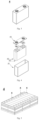
- a third aspect of the present application provides a battery module including the secondary battery according to the first aspect of the present application or the secondary battery prepared by the method according to the second aspect of the present application.
- a fourth aspect of the present application provides a battery pack including the battery module according to the third aspect of the present application.
- a fifth aspect of the present application provides an apparatus including at least one of the secondary battery according to the first aspect of the present application, the secondary battery prepared by the method according to the second aspect of the present application, the battery module according to the third aspect of the present application, and the battery pack according to the fourth aspect of the present application.
- the battery module, battery pack and apparatus at least have advantages identical to the above-mentioned secondary battery.
- any lower limit may be combined with any upper limit to form an unspecified range.
- any lower limit may be combined with other lower limits to form an unspecified range; likewise, any upper limit may be combined with any other upper limit to form an unspecified range.
- each point or single value between the end points of a range is included in the range. Therefore, each point or single value, as the lower limit or upper limit thereof, may be combined with any other point or single value, or with other lower limit or upper limit, to form an unspecified range.
- the first aspect according to the present application provides a secondary battery.
- a secondary battery usually includes a positive plate, a negative plate, a separator, and an electrolyte.
- active ions repeatedly intercalate into and deintercalate out of the positive plate or the negative plate.
- the separator arranged between the positive plate and the negative plate, can insulate electrons to prevent internal short circuits, and enable active ions to penetrate and move between the positive and negative electrodes.
- the electrolyte has a function of transferring ions between the positive plate and the negative plate.
- the negative plate according to the present application includes a negative current collector and a negative electrode film arranged on at least one surface of the negative current collector.
- the negative electrode film includes a negative active material.
- the negative active material comprises a first material and a second material, wherein the first material includes artificial graphite and the second material includes natural graphite.
- the artificial graphite includes primary particles and secondary particles, wherein the number percentage S of the secondary particles in the negative active material satisfies: 10% ⁇ S ⁇ 50%.
- the number percentage S of the secondary particles in the negative active material may fall within the numerical range with the end points being selected from any two of values listed as follows: 10%, 13%, 15% , 17%, 20%, 23%, 25%, 30%, 33%, 35%, 40%, 42%, 45%, 48%, 50%.
- S may satisfy: 15% ⁇ S ⁇ 50%, 20% ⁇ S ⁇ 48%, 25% ⁇ S ⁇ 50%, 30% ⁇ S ⁇ 50%, 10% ⁇ S ⁇ 30%, 15% ⁇ S ⁇ 30%, and 20% ⁇ S ⁇ 45%.
- the inventor of the present application after intensive research found that, when the negative active material of the negative electrode film includes artificial graphite and natural graphite, and the artificial graphite includes primary particles and secondary particles, and when the number percentage of secondary particles in the negative active material falls within a specific range, the negative plate can have reduced cyclic expansion during the charge and discharge process, and at the same time can have higher reversible capacity and higher active ion transportation performance, thereby effectively improving the high temperature cycle performance and dynamic performance of the secondary battery.
- S exceeds 50% the contact area between the active material particles and the current collector is insufficient, and thus the film and the current collector are likely to separate during the battery cycle; this would affect the electron transmission path and further fade the capacity rapidly, thereby affecting the cycle performance at high-temperature of the battery.
- Primary particles refer to particles in a non-agglomerated state.
- Secondary particles refer to the agglomerated particles formed by the aggregation of two or more primary particles.
- Primary particles and secondary particles can be distinguished by using scanning electron microscope (SEM) images.
- the number percentage of secondary particles in the negative active material S means: taking a test sample randomly from the negative electrode film, taking multiple test areas on the test sample, and obtaining the images of the multiple test areas by means of scanning electron microscope SEM, and calculating the ratio of the number of negative active material particles having secondary particle morphology to the total number of the negative active material, wherein the average of multiple calculated results is the number percentage of secondary particles in the negative active material.
- Artificial graphite usually refers to graphite materials obtained through graphitization treatment under high temperature, and it has high graphitization and crystallization degree.
- the crystal lattice structure of artificial graphite tends to long-range orderly layered arrangement, the lattice arrangement of which may be observed by means of transmission electron microscope (TEM).
- TEM transmission electron microscope
- Natural graphite usually refers to the graphite formed naturally in nature and does not need to be graphitized.
- Graphite material may be obtained by subjecting the flake graphite to spheroidizing and purifying process.
- Natural graphite particle usually has many closed-pore structures therein.
- Artificial graphite and natural graphite may be distinguished by a test conducted on cross-section ion polisher.
- the material type may be observed by preparing the negative active into a negative plate and subjecting the negative plate to the ion polished cross-sectional morphology (CP) test.
- CP cross-sectional morphology
- the test method may be: preparing the artificial graphite into a negative plate, cutting the prepared negative plate into a tested sample having a certain size (for example, 2cm ⁇ 2cm), and fixing the negative plate on the sample table with paraffin wax; afterwards, installing the sample stage onto a sample rack and locking it to fix; turning on the power of the cross-section argon ion polisher (for example IB-19500CP) and vacuumizing (for example to 10 -4 Pa); setting the argon flow (for example as 0.15MPa), voltage (for example as 8KV) and polishing time (for example as 2 hours); and adjusting the sample stage to swing mode to start polishing.
- Sample test may refer to JY/T010-1996.
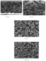
- Fig. 1-1 is an example of the artificial graphite according to the present application. It can be seen from Fig. 1-1 that the material particles are compact and have less pores inside.
- Fig. 1-2 is an example of the natural graphite according to the present application. As compared with Fig. 1-1 , the material particles of Fig. 1-2 have more pores inside, most of which have closed-pore structure.
- the test may be conducted as follows: randomly selecting multiple (for example, 10 or 20) different areas on the tested sample, calculating the number of the secondary particles and the total number of particles in the test area at certain magnification (for example, 500 times or 1000 times), wherein the ratio of the number of secondary particles to the total number of particles in any test area is the number percentage of the secondary particles in the area, and the average of the test results of 10 test areas is taken as the number percentage of the secondary particles.
- multiple test samples (for example, 5 or 10) may prepared to repeat the above test, wherein the average of the test results of each test sample is taken as the number percentage of the secondary particles in the negative active material. For example, Figs.
- 2-1 and 2-2 are scanning electron microscope (SEM) images of the negative active material in the negative electrode film according to specific embodiments of the present application. It can be seen from Figs. 2-1 and 2-2 that the negative active material includes artificial graphite and natural graphite, and the artificial graphite includes primary particles and secondary particles. The number percentage of secondary particles in the negative active material can be calculated from the SEM image.
- S is related to the intrinsic parameters of the active material and the formulation design of the plate. Those skilled in the art, by adjusting the above parameters, could obtain the number percentage of the secondary particles according to the present application. For example, when the type of artificial graphite and natural graphite are set (that is, specific artificial graphite and natural graphite are selected), S may be adjusted by changing the mixing ratio of artificial graphite to natural graphite and the preparation process of the plate (such as the compaction density of the plate).
- S may be adjusted by changing the preparation process of artificial graphite and/or natural graphite (such as raw material type, shaping process, granulation process), the intrinsic parameters of artificial graphite (such as volume average particle size and material morphology), and the preparation process of plate (such as the compaction density of the plate).
- preparation process of artificial graphite and/or natural graphite such as raw material type, shaping process, granulation process
- the intrinsic parameters of artificial graphite such as volume average particle size and material morphology
- the preparation process of plate such as the compaction density of the plate.
- the volume average particle size D v 50 of the negative active material may be from 8.0 ⁇ m to 19.0 ⁇ m.
- the volume average particle size D v 50 of the negative active material may fall within the numerical range with the end points being selected from any two of values listed as follows: 8.0 ⁇ m, 8.5 ⁇ m, 8.9 ⁇ m, 9.0 ⁇ m, 9.2 ⁇ m, 9.6 ⁇ m, 10.0 ⁇ m, 10.2 ⁇ m, 10.5 ⁇ m, 10.8 ⁇ m, 11.3 ⁇ m, 11.6 ⁇ m, 11.9 ⁇ m, 12.2 ⁇ m, 12.4 ⁇ m, 12.8 ⁇ m, 13.2 ⁇ m, 13.5 ⁇ m, 14.0 ⁇ m, 14.2 ⁇ m, 14.5 ⁇ m, 15.0 ⁇ m, 15.5 ⁇ m, 15.9 ⁇ m, 16.0 ⁇ m, 16.3 ⁇ m, 16.5 ⁇ m, 17.0 ⁇ m, 17.5 ⁇ m, 18.0 ⁇ m, 18.4 ⁇ m, and 19.0 ⁇ m.
- the volume average particle size D v 50 of the negative active material may be from 8.0 ⁇ m to 17.5 ⁇ m, from 8.0 ⁇ m to 15.5 ⁇ m, from 8.0 ⁇ m to 14.5 ⁇ m, from 8.0 ⁇ m to 14.0 ⁇ m, from 8.0 ⁇ m to 12.0 ⁇ m, from 8.5 ⁇ m to 13.5 ⁇ m, from 8.5 ⁇ m to 13.0 ⁇ m, from 8.5 ⁇ m to 12.5 ⁇ m, from 8.5 ⁇ m to 11.5 ⁇ m, from 9.0 ⁇ m to 18.0 ⁇ m, from 9.0 ⁇ m to 16.5 ⁇ m, from 9.0 ⁇ m to 14.2 ⁇ m, from 9.0 ⁇ m to 13.5 ⁇ m, from 9.2 ⁇ m to 14.0 ⁇ m, from 10.0 ⁇ m to 13.5 ⁇ m, from 11.0 ⁇ m to 19.0 ⁇ m, from 11.0 ⁇ m to 15.0 ⁇ m, from 11.5 ⁇ m to 18.0 ⁇ m, from 12.0 ⁇ m to 18.0 ⁇ m, from 12.0 ⁇ m to 14.0 ⁇ m, from 13.0 ⁇ m to 19.0 ⁇ m, from 14.0 ⁇ m, from
- the inventors lists the above values in an alternative way, it does not mean that the negative active material, having a volume average particle size D v 50 falling within the numerical range with the end points being any two of values listed above, can achieve equivalent or similar performance.
- the preferable range of the volume average particle size D v 50 of the negative active material according to the present application it can be selected based on the specific discussion and specific experimental data herein below. Likewise, this would apply to the parameters listed below.
- the volume average particle size D v 50 of the artificial graphite may be from 10.0 ⁇ m to 19.0 ⁇ m.
- the volume average particle size D v 50 of artificial graphite may fall within the numerical range with the end points being selected from any two of values listed as follows: 10.0 ⁇ m, 11.0 ⁇ m, 12.0 ⁇ m, 13.0 ⁇ m, 13.5 ⁇ m, 14.5 ⁇ m, 15.0 ⁇ m, 16.0 ⁇ m, 17.0 ⁇ m, 18.0 ⁇ m, and 19.0 ⁇ m.
- the volume average particle size D v 50 of artificial graphite may be from 10.0 ⁇ m to 19.0 ⁇ m, from 12.0 ⁇ m to 18.0 ⁇ m, from 13.0 ⁇ m to 17.0 ⁇ m, from 10.0 ⁇ m to 14.5 ⁇ m, from 11.0 ⁇ m to 13.5 ⁇ m, from 12.0 ⁇ m to 16.0 ⁇ m, from 13.0 ⁇ m to 15.0 ⁇ m, from 14.0 ⁇ m to 18.0 ⁇ m, from 15.0 ⁇ m to 19.0 ⁇ m, from 15.0 ⁇ m to 18.0 ⁇ m, and from 15.0 ⁇ m to 17.0 ⁇ m.
- the volume average particle size D v 50 of the natural graphite may be from 7.0 ⁇ m to 20.0 ⁇ m.
- the volume average particle size D v 50 of natural graphite may fall within the numerical range with the end points being selected from any two of values listed as follows: 7.0 ⁇ m, 10.0 ⁇ m, 11.0 ⁇ m, 13.0 ⁇ m, 14.0 ⁇ m, 15.0 ⁇ m, 16.0 ⁇ m, 18.0 ⁇ m, 19.0 ⁇ m, and 20.0 ⁇ m.
- the volume average particle size D v 50 of natural graphite may be from 7.0 ⁇ m to 20.0 ⁇ m, from 7.0 ⁇ m to 14.0 ⁇ m, from 7.0 ⁇ m to 13.0 ⁇ m, from 10.0 ⁇ m to 19.0 ⁇ m, from 10.0 ⁇ m to 14.0 ⁇ m, from 11.0 ⁇ m to 18.0 ⁇ m, from 11.0 ⁇ m to 13.0 ⁇ m, from 15.0 ⁇ m to 20.0 ⁇ m, from 15.0 ⁇ m to 19.0 ⁇ m, from 16.0 ⁇ m to 19.0 ⁇ m, and from 16.0 ⁇ m to 18.0 ⁇ m.
- the volume particle size distribution D v 90 of the negative active material may be from 16.0 ⁇ m to 33.0 ⁇ m.
- the volume particle size distribution D v 90 of the negative active material may fall within the numerical range with the end points being selected from any two of values listed as follows: 16.0 ⁇ m, 20.0 ⁇ m, 25.0 ⁇ m, 26.0 ⁇ m, 30.0 ⁇ m, 32.0 ⁇ m, and 33.0 ⁇ m.
- the volume particle size distribution D v 90 of the negative active material may be from 16.0 ⁇ m to 25.0 ⁇ m, from 20.0 ⁇ m to 25.0 ⁇ m, from 25.0 ⁇ m to 32.0 ⁇ m, and from 26.0 ⁇ m to 30.0 ⁇ m.
- the volume particle size distribution D v 90 of the artificial graphite may be 23.0 ⁇ m to 37.0 ⁇ m.
- the volume particle size distribution D v 90 of artificial graphite may fall within the numerical range with the end points being selected from any two of values listed as follows: 23.0 ⁇ m, 25.0 ⁇ m, 27.0 ⁇ m, 29.0 ⁇ m, 30.0 ⁇ m, 33.0 ⁇ m, and 37.0 ⁇ m.
- the volume particle size distribution D v 90 of artificial graphite may be from 23.0 ⁇ m to 30.0 ⁇ m, from 25.0 ⁇ m to 29.0 ⁇ m, from 25.0 ⁇ m to 37.0 ⁇ m, and from 27.0 ⁇ m to 33.0 ⁇ m.
- the volume particle size distribution D v 90 of natural graphite may be from 15.0 ⁇ m to 35.0 ⁇ m.
- the volume particle size distribution D v 90 of natural graphite may fall within the numerical range with the end points being selected from any two of values listed as follows: 15.0 ⁇ m, 18.0 ⁇ m, 21.0 ⁇ m, 23.0 ⁇ m, 25.0 ⁇ m, 31.0 ⁇ m, and 35.0 ⁇ m, for example, the volume particle size distribution D v 90 of natural graphite may be from 15.0 ⁇ m to 23.0 ⁇ m, from 18.0 ⁇ m to 21.0 ⁇ m, from 25.0 ⁇ m to 35.0 ⁇ m, and from 25.0 ⁇ m to 31.0 ⁇ m.
- the volume particle size distribution D v 99 of the negative active material may be from 25.0 ⁇ m to 43.0 ⁇ m.
- the volume particle size distribution Dv99 of the negative active material may fall within the numerical range with the end points being selected from any two of values listed as follows: 25.0 ⁇ m, 33.0 ⁇ m, 35.0 ⁇ m, 36.5m, 37.0 ⁇ m, 38.0 ⁇ m, 40.0 ⁇ m, 42.0 ⁇ m, and 43.0 ⁇ m.
- the volume particle size distribution D v 99 of the negative active material may be from 25.0 ⁇ m to 37.0 ⁇ m, from 33.0 ⁇ m to 36.5 ⁇ m, from 35.0 ⁇ m to 42.0 ⁇ m, and from 38.0 ⁇ m to 40.0 ⁇ m.
- the volume particle size distribution D v 99 of the artificial graphite may be from 30.0 ⁇ m-50.0 ⁇ m.
- the volume particle size distribution D v 99 of the artificial graphite may fall within the numerical range with the end points being selected from any two of values listed as follows: 30.0 ⁇ m, 32.0 ⁇ m, 38.0 ⁇ m, 40.0 ⁇ m, 43.0 ⁇ m, 45.0 ⁇ m, 48.0 ⁇ m, and 50.0 ⁇ m, for example, the volume particle size distribution D v 99 of artificial graphite may be from 30.0 ⁇ m to 45.0 ⁇ m, from 32.0 ⁇ m to 43.0 ⁇ m, from 38.0 ⁇ m to 50.0 ⁇ m, and from 40.0 ⁇ m to 48.0 ⁇ m.
- the volume particle size distribution D v 99 of natural graphite may be from 21.0 ⁇ m to 48.0 ⁇ m.
- the volume particle size distribution D v 99 of natural graphite may fall within the numerical range with the end points being selected from any two of values listed as follows: 21.0 ⁇ m, 25.0 ⁇ m, 30.0 ⁇ m, 32.0 ⁇ m, 35.0 ⁇ m, 45.0m, and 48.0 ⁇ m, for example, the volume particle size distribution D v 99 of natural graphite may be from 21.0 ⁇ m to 35.0 ⁇ m, from 25.0 ⁇ m to 30.0 ⁇ m, from 30.0 ⁇ m to 48.0 ⁇ m, and from 32.0 ⁇ m to 45.0 ⁇ m.
- the particle size distribution (D v 90-D v 10)/D v 50 of the negative active material may be from 1.10 to 1.60.
- the particle size distribution (D v 90-D v 10)/D v 50 of the negative active material may fall within the numerical range with the end points being selected from any two of values listed as follows: 1.10, 1.25, 1.30, 1.35, 1.50, 1.55, and 1.60.
- the particle size distribution (D v 90-D v 10)/D v 50 of the negative active material may be from 1.10 to 1.50, from 1.10 to 1.30, from 1.10 to 1.25, from 1.30 to 1.55, from 1.35 to 1.55, and from 1.50 to 1.50.
- the particle size distribution (D v 90-D v 10)/D v 50 of the negative active material may be from 1.25 to 1.95.
- the particle size distribution (D v 90-D v 10)/D v 50 of artificial graphite may fall within the numerical range with the end points being selected from any two of values listed as follows: 1.25, 1.30, 1.35, 1.45, 1.65, 1.80, and 1.95, for example, the particle size distribution (D v 90-D v 10)/D v 50 of artificial graphite may be from 1.25 to 1.95, from 1.25 to 1.65, from 1.30 to 1.45, and from 1.35 to 1.80.
- the particle size distribution (D v 90-D v 10)/D v 50 of the negative active material may be from 0.88 to 1.30.
- the particle size distribution (D v 90-D v 10)/D v 50 of natural graphite may fall within the numerical range with the end points being selected from any two of values listed as follows: 0.88, 0.90, 0.98, 1.05, 1.18, 1.25, 1.28, and 1.30, for example, the particle size distribution (D v 90-D v 10)/D v 50 of natural graphite may be from 0.88 to 1.28, from 0.90 to 1.30, from 0.98 to 1.18, and from 1.05 to 1.25.
- D v 99, D v 90, D v 50, and D v 10 of the negative active material artificial graphite and natural graphite have the meanings well-known in the art, and can be tested by methods well-known in the art.
- the test may be conducted by means of a laser particle size analyzer (such as Malvern Master Size 3000) with reference to the standard GB/T 19077.1-2016.
- D v 99 refers to the particle size at which the cumulative volume distribution percentage of the material reaches 99%
- D v 90 refers to the particle size at which the cumulative volume distribution percentage of the material reaches 90%
- D v 50 refers to the particle size at which the cumulative volume distribution percentage of the material reaches 50%
- Dv10 refers to the particle size at which the cumulative volume distribution percentage of the material reaches 10%.
- the number percentage of the secondary particles in the artificial graphite may be from 25% to 80%.
- the number percentage of the secondary particles in the artificial graphite may fall within the numerical range with the end points being selected from any two of values listed as follows: 25%, 30%, 35%, 40%, 45%, 50%, 55%, 60%, 65%, 70%, 75%, and 80%.
- the number percentage of secondary particles in artificial graphite may be from 25% to 60%, from 30% to 50%, from 30% to 45%, from 35% to 50%, from 35% to 45%, from 50% to 80%, from 55% to 75%, from 60% to 75%, and from 65% to 80%.
- the natural graphite includes primary particles, and the number percentage of primary particles in the natural graphite may be ⁇ 90%; for example, ⁇ 95%, ⁇ 97%, ⁇ 98%.
- all the natural graphite is primary particles (that is, the number percentage of the primary particles in the natural graphite is 100%).
- the tap density of the negative active material may be from 1.0 g/cm 3 to 1.3 g/cm 3 .
- the tap density of the negative active material may fall within the numerical range with the end points being selected from any two of values listed as follows: 1.0g/cm 3 , 1.05g/cm 3 , 1.09g/cm 3 , 1.10g/cm 3 , 1.15g /cm 3 , 1.2g/cm 3 , and 1.3g/cm 3 .
- the tap density of the negative active material may be from 1.05g/cm 3 to 1.2g/cm 3 , from 0.90g/cm 3 to 1.20g/cm 3 , from 1.0g/cm 3 to 1.09g/cm 3 , from 1.05g/cm 3 to 1.15g/cm 3 , and from 1.10g/cm 3 to 1.15g/cm 3 .
- the tap density of the negative active material has a well-known meaning in the art, and can be tested by methods well-known in the art.
- the test may be conducted on a powder tap density tester (such as Dandong Baxter BT-301) with reference to the standard GB/T 5162-2006.
- the tap density of the artificial graphite may be from 0.85 g/cm 3 to 1.35 g/cm 3 .
- the tap density of artificial graphite may fall within the numerical range with the end points being selected from any two of values listed as follows: 0.85g/cm 3 , 0.90g/cm 3 , 0.95g/cm 3 , 1.05g/cm 3 , 1.15g/ cm 3 , 1.18g/cm 3 , 1.2g/cm 3 , 1.25g/cm 3 , 1.30g/cm 3 , and 1.35g/cm 3 .
- the tap density of artificial graphite may be from 0.85g/cm 3 to 1.25g/cm 3 , from 0.90g/cm 3 to 1.18g/cm 3 , from 0.90g/cm 3 to 1.35g/cm 3 , from 0.9g/cm 3 to 1.30g/cm 3 , from 0.9g/cm 3 to 1.20g/cm 3 , from 0.95g/cm 3 to 1.15g/cm 3 , from 1.05g/cm 3 to 1.15g/cm 3 , and from 1.15g/cm 3 to 1.30g/cm 3 .
- the tap density of natural graphite may be from 0.80 g/cm 3 to 1.35 g/cm 3 .
- the tap density of natural graphite may fall within the numerical range with the end points being selected from any two of values listed as follows: 0.80g/cm 3 , 0.90g/cm 3 , 0.93g/cm 3 , 0.95g/cm 3 , 1.00g/ cm 3 , 1.13g/cm 3 , 1.15g/cm 3 , 1.18g/cm 3 , 1.20g/cm 3 , 1.30g/cm 3 , 1.35g/cm 3 .
- the tap density of natural graphite may be from 0.8g/cm 3 to 1.35g/cm 3 , from 0.80g/cm 3 to 1.30g/cm 3 , from 0.90g/cm 3 to 1.18g/cm 3 , from 0.90g/cm 3 to 1.20g/cm 3 , from 0.93g/cm 3 to 1.13g/cm 3 , from 0.95g/cm 3 to 1.2g/cm 3 , from 0.95g/cm 3 to 1.15g/cm 3 , and from 1.00g/cm 3 to 1.20g/cm 3 .
- the graphitization degree of the negative active material may be from 92% to 96%.
- the graphitization degree of the negative active material may fall within the numerical range with the end points being selected from any two of values listed as follows: 92%, 92.3%, 92.7%, 93%, 93.4%, 94%, 94.2%, 94.4 %, 94.7%, 95%, 95.2%, 95.5%, and 96%.
- the graphitization degree of the negative active material may be from 92% to 95%, from 93% to 95%, from 93% to 94%, from 94% to 96%, and from 94.2% to 95.5%.
- the graphitization degree of the artificial graphite may be from 90% to 95%.
- the graphitization degree of artificial graphite may fall within the numerical range with the end points being selected from any two of values listed as follows: 90%, 91%, 92%, 93%, 94%, and 95%, for example, the graphitization degree of the artificial graphite may be from 91% to 94%, from 91% to 93%, from 92% to 95%, and from 93% to 95%.
- the graphitization degree of natural graphite may be from 93% to 98%.
- the graphitization degree of natural graphite may fall within the numerical range with the end points being selected from any two of values listed as follows: 93%, 94%, 95%, 96%, 97%, and 98%, for example, the graphitization degree of natural graphite may be from 94% to 98%, from 94% to 97%, from 95% to 98%, from 95% to 97%, and from 96% to 97%.
- the degree of graphitization degree of the negative active material, natural graphite, and artificial graphite has a well-known meaning in the art, and can be tested by a method well-known in the art.
- the test may be conducted on an X-ray diffraction instrument (such as Bruker D8 Discover).
- the artificial graphite does not have a coating layer on its surface.
- the artificial graphite according to the present application has a relatively stable surface. When there is not a coating layer on the surface, it is beneficial to maintain its lower reactivity (because the carbon coating layer has a reactivity higher than that the surface of the artificial graphite substrate according to the present application), and thus is beneficial to reduce the side reactions during the battery cycle, thereby further improving the cycle performance of the battery at high temperature.
- the natural graphite has a coating layer (for example, a carbon coating layer) on its surface.
- a coating layer for example, a carbon coating layer
- the natural graphite according to the present application has a high surface activity, and a coating layer formed on its surface may reduce its surface activity (because natural graphite has many defects on the surface after being subjected to spheroidization and purification treatment, the coating layer formed by carbonization could effectively repair surface defects, and thus reduce side reactions during cycling), thereby further improving the cycling performance of the battery at high temperature.
- the carbon coating layer may be formed on the surface of natural graphite by the calcination and thermal decomposition of petroleum or coal pitch.
- the transmission electron microscope (TEM) image may be used to test whether or not there is a coating layer on the surface of artificial graphite and natural graphite.
- the test may be conducted as follows: selecting a micro-grid having certain diameter (for example, 3mm in diameter); clamping the edge of the micro-grid with pointed tweezers, with the film side turning up (observing the glossy surface i.e.
- the mass percentage of natural graphite in the negative active material is less than or equal to 50%, for example, it may be from 10% to 50%.
- the mass percentage of natural graphite in the negative active material may fall within the numerical range with the end points being selected from any two of values listed as follows: 10%, 15%, 20%, 25%, 30%, 35%, 40%, 45%, and 50%.
- the mass percentage of natural graphite in the negative active material may be from 10% to 30%, from 15% to 25%, from 20% to 50%, from 35% to 50%, and from 35% to 45%.
- the negative current collector may be made of materials having good electrical conductivity and mechanical strength, serving as conducting electricity and collecting current.
- copper foil may be used as the negative current collector.
- the negative current collector has two surfaces that are opposite in its thickness direction, and the negative electrode film is laminated on either or both of the surfaces of the negative current collector.
- negative active material may comprise other active materials which may include, but are not limited to, one or more of hard carbon, soft carbon, silicon-based materials, and tin-based materials.
- the silicon-based material may be one or more selected from elementary silicon, silicon-oxygen compounds, silicon-carbon composites, silicon-nitrogen compounds, and silicon alloys.
- the tin-based material may be one or more selected from elementary tin, tin oxide compounds, and tin alloys.
- the negative electrode film may further include a binder.
- the binder used for the negative electrode film may be one or more selected from polyacrylic acid (PAA), sodium polyacrylate (PAAS), polyacrylamide (PAM), polyvinyl alcohol (PVA), styrene butadiene rubber (SBR), seaweed sodium (SA), polymethacrylic acid (PMAA) and carboxymethyl chitosan (CMCS).
- the negative electrode film further includes a thickener.
- the thickener may be sodium carboxymethyl cellulose (CMC-Na).
- the negative electrode film further includes a conductive agent.
- the conductive agent used for the negative electrode film may be one or more selected from superconducting carbon, acetylene black, carbon black, Ketjen black, carbon dots, carbon nanotubes, graphene, and carbon nanofibers.
- the areal density of the negative electrode film prepared using the above-mentioned negative active material may be from 7mg/cm 2 to 13mg/cm 2 .
- the areal density of the negative electrode film may fall within the numerical range with the end points being selected from any two of values listed as follows: 7mg/cm 2 , 8mg/cm 2 , 10mg/cm 2 , 10.5mg/cm 2 , 11.5mg/cm 2 , and 13.0 mg/cm 2 .
- the areal density of the negative electrode film may be from 7mg/cm 2 to 10mg/cm 2 , from 7mg/cm 2 to 8mg/cm 2 , from 10.0mg/cm 2 to 13.0mg/cm 2 , and from 10.5mg/cm 2 to 11.5mg/cm 2 .
- the areal density of the negative electrode film has a meaning well-known in the art, and may be measured using instruments and methods well-known in the art.
- the test comprises: taking a cold-pressed negative electrode plate; punching it into a small round having an area of S1; weighing it, recording the weight as M1; then wiping off the negative electrode films of the above weighted negative plate; weighting the negative current collector, recording the weight as M0.
- Areal density of the negative electrode film weight of the negative electrode film / S1.
- the compaction density of the negative electrode film prepared using the above-mentioned negative active material may be from 1.40 g/cm 3 to 1.80 g/cm 3 .
- the compaction density of the negative electrode film may fall within the numerical range with the end points being selected from any two of values listed as follows: 1.40g/cm 3 , 1.50g/cm 3 , 1.40g/cm 3 , 1.55g/cm 3 , 1.60g /cm 3 , 1.65g/cm 3 , 1.68g/cm 3 , 1.70g/cm 3 , 1.73g/cm 3 , 1.75g/cm 3 , and 1.80g/cm 3 .
- the compacted density of the negative electrode film may be from 1.50g/cm 3 to 1.70g/cm 3 , from 1.55g/cm 3 to 1.60g/cm 3 , from 1.60g/cm 3 to 1.80g/cm 3 , from 1.65g/cm 3 to 1.75g/cm 3 , and from 1.68g/cm 3 to 1.73g/cm 3 .
- the compaction density of the negative electrode film has a meaning well-known in the art, and may be tested by a method well-known in the art.
- the test comprises: taking a cold-pressed negative plate, measuring the thickness of the negative electrode film (here, measuring the thickness of the negative electrode film on any surface of the negative current collector), and then testing the areal density of the negative electrode film according to the above-mentioned method.
- Compaction density of the negative electrode film areal density of the negative electrode film / thickness of the negative electrode film.
- the cohesion force F of the negative electrode film prepared using the above-mentioned negative active material may satisfy 150N/m ⁇ F ⁇ 300N/m.
- the cohesion force F of the negative electrode film may fall within the numerical range with the end points being selected from any two of values listed as follows: 150N/m, 180N/m, 220N/m, 240N/m, 250N/m, 260N/m, and 300N/m.
- the cohesion force F of the negative electrode film may be from 150N/m to 250N/m, from 180N/m to 220N/m, from 220N/m to 300N/m, and from 240N/m to 260N/m.
- the cohesion of the negative electrode film has a meaning well-known in the art, and may be tested by methods well-known in the art.
- An exemplary test method is as follows: taking a cold-pressed negative plate (if two sides of the negative plate are coated as negative electrode film, wiping off the negative electrode film on one side); cutting the negative plate into a sample to be tested having a length of 100mm and a width of 10mm; taking a stainless steel plate having a width of 25mm; pasting a double-sided tape (having a width of 11mm) on the stainless steel plate, and then pasting the sample to be tested on the double-sided tape pasted on the stainless steel plate, with the negative current collector being bonded to the double-sided tape; rolling with a 2000g pressure roller on the tested sample back and forth for three times at a rate of 300mm/min; then pasting a tape having a width of 10 mm and a thickness of 50 ⁇ m on the surface of the negative electrode film, and rolling with a 2000 g pressure roller on the surface thereof
- test sample is sampled for testing during preparing the battery or from the readily prepared secondary battery.
- sampling may be conducted as follows:
- the positive plate may include a positive current collector and a positive film arranged on at least one surface of the positive current collector.
- the positive current collector has two surfaces opposite in the thickness direction thereof, and the positive electrode film is laminated on either or both of the two surfaces.
- the positive current collector may be made of materials having good electrical conductivity and mechanical strength, serving to conduct electricity and collect current.
- aluminum foil may be used as the positive current collector.
- the positive film includes a positive active material.
- Positive active material for secondary battery well-known in the art may be used as the positive active material.
- the positive active material may include one or more of layered lithium transition metal oxides and the modified compounds thereof, olivine-structured lithium-containing phosphates and modified compounds thereof, and the like.
- the positive active material includes layered lithium transition metal oxides and the modified compounds thereof.
- layered lithium transition metal oxides may include, but are not limited to, one or more of lithium cobalt oxide, lithium nickel oxide, lithium manganese oxide, lithium nickel cobalt oxide, lithium manganese cobalt oxide, lithium nickel manganese oxide, lithium nickel cobalt manganese oxide, lithium nickel cobalt aluminum oxide and the modified compounds thereof.
- the layered lithium transition metal oxide may be one or more selected from lithium nickel cobalt manganese oxide, lithium nickel cobalt aluminum oxide and modified compounds thereof.
- the modified compound of the layered lithium transition metal oxide may be the layered lithium transition metal oxide that is subjected to doping modification and/or surface coating modification.
- the positive active material includes layered lithium transition metal oxides and the modified compounds thereof (especially including lithium nickel cobalt manganese oxide, lithium nickel cobalt aluminum oxide and the modified compounds thereof), and the negative active material includes artificial graphite and natural graphite, wherein the artificial graphite includes primary particles and secondary particles, with the number percentage S of the secondary particles in the negative active material satisfying: 10% ⁇ S ⁇ 50%.
- S satisfies 10% ⁇ S ⁇ 30%, such as 15% ⁇ S ⁇ 30%, such as 20%, 25% and 30%, the battery have good dynamic performance and simultaneously cycle performance at high temperature.
- the inventors of the present application after reaching, has further found that, when the positive active material includes one or more of layered lithium transition metal oxides and the modified compounds thereof (especially including lithium nickel cobalt manganese oxide, lithium nickel cobalt aluminum oxide and the modified compounds thereof), when the negative active material includes artificial graphite and natural graphite, when the artificial graphite includes primary particles and secondary particles both, and when the number percentage S of secondary particles in the negative active material satisfies the range provided according to the present application;, the performance of the battery may be further improved in the event that the negative active material optionally further satisfies one or more of the following conditions.
- the positive active material includes one or more of layered lithium transition metal oxides and the modified compounds thereof (especially including lithium nickel cobalt manganese oxide, lithium nickel cobalt aluminum oxide and the modified compounds thereof)
- the negative active material includes artificial graphite and natural graphite
- the artificial graphite includes primary particles and secondary particles both
- the number percentage S of secondary particles in the negative active material satisfies the
- the volume average particle size D v 50 of the negative active material is less than or equal to 14.0 ⁇ m.
- the volume average particle size D v 50 of the negative active material may fall within the numerical range with the end points being selected from any two of values listed as follows: 8.0 ⁇ m, 8.5 ⁇ m, 8.9 ⁇ m, 9.0 ⁇ m, 9.2 ⁇ m, 9.6 ⁇ m, 10.0 ⁇ m , 10.2 ⁇ m, 10.5 ⁇ m, 10.8 ⁇ m, 11.2 ⁇ m, 11.6 ⁇ m, 11.9 ⁇ m, 12.2 ⁇ m, 12.4 ⁇ m, 12.8 ⁇ m, 13.1 ⁇ m, 13.2 ⁇ m, 13.5 ⁇ m, 13.8 ⁇ m, 13.9 ⁇ m, and 14.0 ⁇ m.
- the volume average particle size D v 50 of the negative active material may be from 8.0 ⁇ m to 14.0 ⁇ m, from 8.0 ⁇ m to 12.0 ⁇ m, from 8.5 ⁇ m to 13.5 ⁇ m, from 8.5 ⁇ m to 13.0 ⁇ m, from 8.5 ⁇ m to 12.5 ⁇ m, from 8.5 ⁇ m to 11.5 ⁇ m, from 8.9 ⁇ m to 12.2 ⁇ m, from 9.0 ⁇ m to 14.0 ⁇ m, from 9.0 ⁇ m to 13.5 ⁇ m, from 9.2 ⁇ m to 14.0 ⁇ m, from 10.0 ⁇ m to 13.5 ⁇ m, from 11.0 ⁇ m to 14.0 ⁇ m, from 11.5 ⁇ m to 13.5 ⁇ m, and from 12.0 ⁇ m to 14.0 ⁇ m.
- the inventors of the present application after researching, has found that, when the positive active material includes one or more of layered lithium transition metal oxide and the modified compounds thereof, S falls within the provided range, and simultaneously Dv50 of the negative active material is adjusted to fall within the provided range, the cyclic expansion rate of the plate may be further reduced without affecting other performances (such as dynamic performance and cycle performance at high temperature), thereby further improving the safety performance of the battery.
- the inventors after researching, has found that, when the positive active material includes one or more of the layered lithium transition metal oxide and the modified compounds thereof, S falls within the provided range, and simultaneously D v 50 of the negative active material falls within the above range, the polarization of the battery may be reduced, the side reactions may be effectively reduced, the probability of lithium precipitation from the plate may be significantly reduced, and the cycle expansion rate of the negative plate may be reduced, thus, the safety performance of the battery is further improved.
- the volume average particle size D v 50 of the artificial graphite may be from 10.0 ⁇ m to 14.5 ⁇ m, and optionally may be from 11.0 ⁇ m-13.5 ⁇ m, for example, is 10.3 ⁇ m, 10.8 ⁇ m, 11.4 ⁇ m, 12.3 ⁇ m, 13.0 ⁇ m, and 14.0 ⁇ m.
- the volume average particle size D v 50 of the natural graphite may be from 7.0 ⁇ m to 14.0 ⁇ m, and optionally may be from 7.0 ⁇ m-13.0 ⁇ m, for example, is 7.1 ⁇ m, 8.7 ⁇ m, 11.2 ⁇ m, 12.1 ⁇ m, 12.4 ⁇ m, and 12.8 ⁇ m.
- the volume particle size distribution D v 90 of the negative active material may be from 16.0 ⁇ m to 25.0 ⁇ m, and optionally may be from 20.0 ⁇ m to 25.0 ⁇ m.
- S falls within the provided range, and simultaneously D v 90 of the negative active material is adjusted to fall within the provided range, good dynamic performance, cycle performance at high temperature and safety performance may be obtained simultaneously.
- the volume particle size distribution Dv90 of the artificial graphite may be from 23.0 ⁇ m to 30.0 ⁇ m, and optionally may be from 25.0 ⁇ m to 29.0 ⁇ m.
- the volume particle size distribution D v 90 of the natural graphite may be from 15.0 ⁇ m to 23.0 ⁇ m, and optionally may be from 18.0 ⁇ m to 21.0 ⁇ m.
- the volume particle size distribution D v 99 of the negative active material may be from 25.0 ⁇ m to 37.0 ⁇ m, and optionally may be from 33.0 ⁇ m to36.5 ⁇ m.
- S falls within the provided range, and simultaneously D v 99 of the negative active material is adjusted to fall within the provided range, the better dynamic performance, cycle performance at high temperature and safety performance of batteries may be obtained simultaneously.
- the volume particle size distribution D v 99 of the artificial graphite may be from 30.0 ⁇ m to 45.0 ⁇ m, and optionally may be from 32.0 ⁇ m to 43.0 ⁇ m.
- the volume particle size distribution D v 99 of the natural graphite may be from 21.0 ⁇ m-35.0 ⁇ m, and optionally may be from 25.0 ⁇ m to 30.0 ⁇ m.
- the particle size distribution (D v 90-D v 10)/D v 50 of the negative active material may be from 1.30 to 1.55, and optionally may be from 1.35 to 1. 5 0.
- S falls within the provided range, and simultaneously particle size distribution (D v 90-D v 10)/D v 50 of the negative active material is adjusted to fall within the provided range, the better dynamic performance, cycle performance at high temperature and safety performance of batteries may be obtained simultaneously.
- the particle size distribution (D v 90-D v 10)/D v 50 of the negative active material may be from 1.25 to 1.95, and optionally may be from 1.35 to 1.80 .
- the particle size distribution (D v 90-D v 10)/D v 50 of the negative active material may be from 0.88 to1.28, and optionally may be from 0.98 to 1.18.
- the number percentage of the secondary particles in the artificial graphite is from 25% to 60%, and optionally is from 30% to 50%.
- the positive active material includes one or more of the layered lithium transition metal oxide and the modified compounds thereof, the energy density of the battery may be much improved, but the cycle life may be relatively poor.
- the number percentage of the secondary particles in the negative active material and that of the secondary particles in the artificial graphite both fall within the provided ranges, the cohesion and adhesive force of the negative electrode film may be effectively improved on the premise of ensuring lower expansion rate of the negative plate. As a result, the cycle performance of the battery at the high temperature is further improved.
- the tap density of the negative active material is ⁇ 1.10 g/cm 3 , and optionally may be from 1.10 g/cm 3 to 1.15 g/cm 3 .
- the positive active material includes one or more of the layered lithium transition metal oxide and the modified compounds thereof, S falls within the provided range, and simultaneously the tap density of the negative active material is adjusted to fall within the provided range, the energy density and dynamic performance of the battery may be further improved.
- the tap density of the artificial graphite may be from 0.90g/cm 3 to 1.20g/cm 3 , and optionally may be from 1.05g/cm 3 to 1.15g/cm 3 .
- the tap density of natural graphite may be from 0.90g/cm 3 to 1.18g/cm 3 , for example, may be from 0.93g/cm 3 to 1.13g/cm 3 .
- the graphitization degree of the negative active material may be from 92% to 96%, and optionally may be from 93% to 95%.
- the positive active material includes one or more of the layered lithium transition metal oxide and the modified compounds thereof, S falls within the provided range, and simultaneously the graphitization degree of the negative active material is adjust to fall within the provided range, the energy density and cycle expansion of the battery may be further improved.
- the graphitization degree of the artificial graphite may be from 92% to 95%, and optionally may be from 93% to 95%.
- the graphitization degree of natural graphite may be from 95% to 98%, for example, may be from 95% to 97%.
- the mass percentage of the natural graphite in the negative active material is ⁇ 30%, for example, it may be from 10% to 30%, and from 15% to 25%.
- the positive active material includes one or more of the layered lithium transition metal oxides and the modified compounds thereof, S falls within the provided range, and simultaneously the mass percentage of the natural graphite in the negative active material is adjusted to fall within the provided range, the high temperature cycle performance and safety performance of the battery may be further improved.
- the gram capacity of the negative active material may be from 351mAh/g to 359mAh/g, and optionally may be from 353mAh/g to 357mAh/g.
- the positive active material includes one or more of the layered lithium transition metal oxide and the modified compounds thereof, S falls within the provided range, and simultaneously the gram capacity of the negative active material is adjusted to fall within the provided range, the dynamic performance and energy density of the secondary battery may be further improved.
- the gram capacity of artificial graphite may be from 349 mAh/g to 357mAh/g, and optionally may be from 351 mAh/g to 355 mAh/g.
- the gram capacity of natural graphite may be from 360 mAh/g to 367 mAh/g, for example, may be from 361 mAh/g to 365 mAh/g.
- the compaction density of the negative electrode film may be from 1.60 g/ cm 3 to 1.80g/cm 3 , for example, may be from 1.65g/cm 3 to 1.75g/cm 3 , from 1.68g/cm 3 to 1.73g/cm 3 .
- the compaction density of the negative electrode film falls within the above range, it is helpful to render the number percentage S of the secondary particles in the negative electrode film fall within the provided range.
- the cycle life of the battery may be further improved and simultaneously the probability of defects on the surface of the negative active material may be effectively reduced, the side reactions are reduced, and the expansion of the battery during cycling is reduced. As a result, the safety performance of the battery may be further improved.
- the areal density of the negative electrode film may be 10.0 mg/cm 2 to 13.0mg/cm 2 , and optional may be 10.5mg/cm 2 to 11.5mg/cm 2 .
- the battery may have a higher energy density, and the battery has better active ions and electrons transportation performance, the dynamic performance of the battery may be further improved, the polarization and side reactions may be further reduced, and thus the cycle performance of the battery may be further improved.
- the cohesion force F of the negative electrode film satisfies: 220N/m ⁇ F ⁇ 300N/m, for example, satisfies 240N/m ⁇ F ⁇ 260N/m.
- the structure of the negative active material may be protected from being damaged; moreover the negative electrode film has a porosity that can make the electrolyte quickly infiltrate, especially the negative electrode film has higher active ions and electrons transportation performance, and the cycle expansion force of batteries may be reduced simultaneously. Therefore, by using the negative electrode film, the cycle performance and dynamic performance of the battery may be further improved.
- the cohesion of the negative electrode film is controlled within an appropriate range, the amount of binder added in the negative electrode film may be reduced.
- the positive active material includes a layered lithium transition metal oxide having a general formula of Li a Ni b Co c M d M' e O f A g , wherein 0.8 ⁇ a ⁇ 1.2, 0 ⁇ b ⁇ 1, 0 ⁇ c ⁇ 1, 0 ⁇ d ⁇ 1 , 0 ⁇ e ⁇ 0.1, 1 ⁇ f ⁇ 2, and 0 ⁇ g ⁇ 1; M is one or more selected from the group consisting of Mn and Al; M' is one or more selected from Zr, Mn, Al, Zn, Cu, Cr, Mg, Fe, V, Ti, and B; and A is one or more selected from N, F, S, and Cl.
- the negative active material according to the present application may be prepared according to the following steps:
- non-needle-like petroleum coke is used as the raw material, the raw material has a volatile content of ⁇ 6% and a sulfur content of ⁇ 1%.
- the non-needle petroleum coke that meets the above conditions has good self-adhesiveness and thus is easy for preparing artificial graphite including secondary particles, which is helpful to obtain the scope of S according to the present application.
- the raw material has a volatile content of 8% to 15%.
- the sulfur content is ⁇ 0.5%.
- the reaction kettle may be a vertical reaction kettle or a horizontal reaction kettle.
- the heating temperature of the raw materials in the reaction kettle may be from 450°C to 700°C, and the holding time may be from 1h to 8h.
- the rotation speed of the mixer during mixing is n ⁇ 500 revolutions/min. If the rotation speed of the mixer is too high, the formed secondary particles will be dispersed to become primary particles, thus the scope of S of the present application may not be satisfied. Moreover, if the rotation speed of the mixer is too high, the defects on the surface of the material will increase, thereby affecting the cycle performance of the battery at high temperature.
- Dv50 of the raw material may be from 7 ⁇ m to 12 ⁇ m.
- Dv50 of the intermediate product 1 may be from 11.5 ⁇ m-20.5 ⁇ m.
- Dv50 of the artificial graphite A may be from 9 ⁇ m to 17.5 ⁇ m.
- the number percentage of secondary particles in artificial graphite A may be from 30% to 70%.
- the temperature for graphitizing may be from 2500°C to 3200°C.
- the needle-like green petroleum coke refers to a raw material that has not been calcined at a high temperature (for example, 1000°C to 1500°C). This material has lower self-adhesiveness, and thus is easy for preparing the artificial graphite including primary particles.
- the rotation speed of the mixer during mixing in step (2) is from 500 revolutions/min to 1000 revolutions/min. It would be helpful to make the number percentage of the secondary particles in the artificial graphite B satisfy ⁇ 3% by controlling the rotation speed within the provided range.
- the required values of D v 50, D v 90, D v 99 and (D v 90-D v 10)/D v 50 of artificial graphite B may be adjusted by adjusting the particle size of the raw material through methods well-known in the art.
- D v 50 of the raw material may be from 5.5 ⁇ m to 11 ⁇ m
- D v 50 of the artificial graphite B may be from 5 ⁇ m to 10.5 ⁇ m.
- the treatment temperature for graphitizing may be from 2500°C to 3200°C.
- the artificial graphite A and the artificial graphite B as prepared above are mixed to obtain the artificial graphite according to the present application.
- the mass percentage of artificial graphite A in the artificial graphite may be from 40% to 75%, and optionally may be from 60% to75%.
- the parameters of artificial graphite may be comprehensively adjusted and controlled according to the ranges as provided above.
- chemically purifying intermediate 1 may be carried out using one or more of hydrochloric acid, hydrofluoric acid, and nitric acid.
- the tap density of the obtained intermediate 1 is ⁇ 0.6 g/cm 3 .
- the carbon content of the obtained intermediate 2 is ⁇ 99.9%.
- the addition amount of the pitch amounts for 2% to 8% by weight of intermediate 2.
- the carbonization treatment may be carried out at a temperature of 900°C to1600°C, for a time of 2 h to 24 h.
- the parameters of natural graphite may be comprehensively adjusted and controlled according to the ranges as provided above.
- the negative active material comprises the artificial graphite and the natural graphite
- the artificial graphite includes primary particles and secondary particles, with a number percentage S of the secondary particles in the negative active materials satisfying: 10% ⁇ S ⁇ 50%.
- the positive active material includes one or more of an olivine-structured lithium-containing phosphates and the doping-modified and/or coating-modified compounds thereof.
- olivine-structured lithium-containing phosphates may include, but are not limited to, one or more of lithium iron phosphates, composites of lithium iron phosphates and carbon, lithium manganese phosphates, composite of lithium manganese phosphates and carbon, lithium iron manganese phosphates, composites of lithium iron manganese phosphates and carbon, and the modified compounds thereof.
- the olivine-structure lithium-containing phosphates are one or more selected from lithium iron phosphates, composite of lithium iron phosphates and carbon, and the modified compounds thereof.
- the positive active material comprises one or more of olivine-structured lithium-containing phosphates and the doping-modified and/or coating-modified compounds thereof
- the negative electrode active material comprises artificial graphite and natural graphite, wherein the artificial graphite includes primary particles and secondary particles, with the number percentage S of the secondary particles in the negative active material satisfying 10% ⁇ S ⁇ 50%.
- the number percentage S of the secondary particles in the negative active material satisfies 15% ⁇ S ⁇ 45%, such as 25% ⁇ S ⁇ 35%, such as 17%, 23%, 25%, 28%, 30%, 32%, 34%, 35% and 42%, the cycle performance at high temperature of the battery may be further improved.
- the positive active material comprises one or more of the olivine-structured lithium-containing phosphates and the doping-modified and/or coating-modified compounds thereof
- the negative active material comprises artificial graphite and natural graphite, wherein the artificial graphite include primary particles and secondary particles, with the number percentage S of secondary particles in the negative active material falling within the range provided in this application, the performance of the battery may be further improved in the event that the negative active material further optionally satisfies one or more of following conditions.
- the volume average particle size D v 50 of the negative active material is ⁇ 15.0 ⁇ m , and optionally may be from 15.0 ⁇ m to 19.0 ⁇ m, and from 16.0 ⁇ m to 18.0 ⁇ m, for example, 15.3 ⁇ m, 15.9 ⁇ m, 16.5 ⁇ m, 16.7 ⁇ m, 17.5 ⁇ m , 18.0 ⁇ m, 18.6 ⁇ m, and 19.0 ⁇ m.
- the positive active material comprises one or more of olivine- structured lithium-containing phosphates and the doping- and/or coating modified compounds thereof, and S falls within the provided range, and simultaneously the volume average particle size D v 50 of the negative active material is adjusted to fall within the provided range, the cycle performance at high temperature of the battery may be further improved.
- the volume average particle size D v 50 of the artificial graphite may be from 14.0 ⁇ m to 19.0 ⁇ m, and optionally may be from 14.0 ⁇ m to 18.0 ⁇ m, from 15.0 ⁇ m to 18.0 ⁇ m, and from 15.0 ⁇ m to 17.0 ⁇ m, for example, 15.1 ⁇ m, 15.8 ⁇ m, 16.6 ⁇ m, 17.1 ⁇ m, 18.0 ⁇ m, 18.6 ⁇ m, and 18.9 ⁇ m.
- the volume average particle size D v 50 of natural graphite may be from 15.0 ⁇ m to 20.0 ⁇ m, and optionally may be from 15.0 ⁇ m to 19.0 ⁇ m, from 16.0 ⁇ m to 19.0 ⁇ m, and from 16.0 ⁇ m to 18.0 ⁇ m, for example, 15.4 ⁇ m, 16.5 ⁇ m, 16.8 ⁇ m, 17.7 ⁇ m, 17.9 ⁇ m, 18.2 ⁇ m, and 18.5 ⁇ m.
- the volume particle size distribution D v 90 of the negative active material may be from 25.0 ⁇ m to 33.0 ⁇ m, and optionally may be from 26.0 ⁇ m to 30.0 ⁇ m.
- the positive active material comprises one or more of the olivine-structured lithium-containing phosphates and the doping-modified and/or coating-modified compounds thereof, S falls within the provided range, and simultaneously D v 90 of the negative active material is adjusted to fall within the provided range, the dynamic performance and cycle performance at high temperature of the battery may be further improved.
- the volume particle size distribution D v 90 of the artificial graphite may be from 25.0 ⁇ m-37.0 ⁇ m, and optionally may be from 27.0 ⁇ m-33.0 ⁇ m.
- the volume particle size distribution D v 90 of the natural graphite may be from 25.0 ⁇ m to 35.0 ⁇ m, and optionally may be from 25.0 ⁇ m to 31.0 ⁇ m.
- the volume particle size distribution D v 99 of the negative active material may be from 35.0 ⁇ m to 43.0 ⁇ m, and optionally may be from 38.0 ⁇ m to 40.0 ⁇ m.
- the positive active material comprises one or more of the olivine-structured lithium-containing phosphate and the doping-modified and/or coating-modified compounds thereof, S falls within the provided range, and simultaneously D v 99 of the negative active material is adjusted to fall within the provided range, the dynamic performance and cycle performance at high temperature of the battery may be further improved.
- the volume particle size distribution D v 99 of the artificial graphite may be from 38.0 ⁇ m to 50.0 ⁇ m, and optionally may be from 40.0 ⁇ m to 48.0 ⁇ m.
- the volume particle size distribution Dv99 of the negative electrode active material may be from 30.0 ⁇ m-48.0 ⁇ m, optionally may be from 32.0 ⁇ m to 45.0 ⁇ m.
- the particle size distribution (D v 90-D v 10)/D v 50 of the negative active material may be from 1.10 to 1.30, and optionally may be from 1.10 to 1.25.
- the positive active material includes one or more of the olivine-structured lithium-containing phosphates and the doping-modified and/or coating-modified compounds thereof, S falls within the provided range, and simultaneously the particle size distribution of the negative active material (D v 90-D v 10)/D v 50 is adjusted to fall within the provided range, the dynamic performance and cycle performance at high temperature of the battery may be further improved.
- the particle size distribution (D v 90-D v 10)/D v 50 of the negative active material may be from 1.25 to 1.65, and optionally may be from 1.35 to 1.45 .
- the particle size distribution (D v 90-D v 10)/D v 50 of the negative active material may be from 0.90 to 1.30, for example may be from 1.05 to 1.25 .
- the number percentage of the secondary particles in the artificial graphite is from 50% to 80%, and optionally from 60% to 75%.
- the positive active material comprises one or more of the olivine-structured lithium-containing phosphates and the doping-modified and/or coating-modified compounds
- S falls within the given range
- the number percentage of the secondary particles in the artificial graphite falls within an appropriate range
- the orientation of the plate after cold pressing may be further improved. This facilitates the intercalation into and de-intercalation of lithium ions, thereby improving the dynamic performance of the secondary battery; meanwhile, this also facilitates the expansion force during the cycle, thereby further improving the manufacturing process (for example, slurry stirring and filtering) of the negative active material.
- the tap density of the negative active material may satisfies ⁇ 1.10 g/cm 3 , and optionally may be from 1.00 g/cm 3 to 1.09 g/cm 3 .
- the positive active material comprises one or more of the olivine-structured lithium-containing phosphates and the doping- and/or coating modified compounds thereof, S falls within the provided range, and simultaneously the tap density of the negative active material is adjusted to fall within the provided range, the cycle performance at high temperature of the battery may be further improved.
- the tap density of the artificial graphite may be from 0.90g/cm 3 to 1.18g/cm 3 , optionally may be from 0.95g/cm 3 to 1.15g/cm 3 .
- the tap density of natural graphite may be from 0.90g/cm 3 to 1.20g/cm 3 , optionally may be from 0.95g/cm 3 to 1.15g/cm 3 .
- the graphitization degree of the negative active material may be from 92% to 95%, and optionally may be from 93% to 94%.
- the positive active material includes one or more of the olivine-structured lithium-containing phosphates and the doping- modified and/or coating-modified compounds, S falls within the provided range, and the graphitization degree of the negative active material is adjusted to fall within the provided range, the secondary battery may have higher energy density and at the same time better cycle performance at high temperature.
- the graphitization degree of the artificial graphite may be from 90% to 95%, and optionally may be from 91% to 93%.
- the graphitization degree of natural graphite may be from 95% to 98%, more optionally may be from 96% to 97%.
- the mass percentage of the natural graphite in the negative active material may be ⁇ 30%, optionally may be from 30% to 50%, and from 35% to 50%.
- the positive active material includes one or more of the olivine-structured lithium-containing phosphates and the doping-modified and/or coating-modified compounds thereof, S falls within the provided range, and simultaneously the mass percentage of the natural graphite in the negative active material is adjusted to fall within the provided range, the battery may have higher energy density and at the same time better dynamic performance.
- the negative electrode film may have a compaction density of 1.5g/cm 3 to 1.7g/cm 3 , more optionally of 1.55g/cm 3 to 1.6g/cm 3 .
- the positive active material comprises one or more of the olivine-structured lithium-containing phosphates and doping-modified and/or coating-modified compounds thereof
- the compaction density of the negative electrode film to fall within the above range, it would be helpful for the number percentage S of the secondary particles in the negative active material falling within the provided range, thereby further improving the cycle life at high temperature of the battery.
- the negative electrode film may have an areal density of 7mg/cm 2 to 10mg/cm 2 , optionally of 7mg/cm 2 to 8mg/cm 2 .
- the cohesion force F of the negative electrode film satisfies: 150N/m ⁇ F ⁇ 250N/m, optionally 180N/m ⁇ F ⁇ 220N/m.
- the negative active material may be prepared by the preparation method as described above, and adjusted for its parameters to satisfy the required range with methods well-known in the art, so as to further improve the performance of the battery wherein the positive active material comprises olivine-structured lithium-containing phosphates and the doping-modified and/or coating-modified compounds thereof.
- the positive film may also optionally include a binder.
- the type of binder is not specifically restricted, and can be selected by those skilled in the art according to actual requirements.
- the binder used for the positive film may include one or more of polyvinylidene fluoride (PVDF) and polytetrafluoroethylene (PTFE).
- the positive film may also optionally include a conductive agent.
- a conductive agent is not specifically restricted, and can be selected by those skilled in the art according to actual requirements.
- the conductive agent used for the positive film may include one or more of graphite, superconducting carbon, acetylene black, carbon black, Ketjen black, carbon dots, carbon nanotubes, graphene, and carbon nanofibers.
- the electrolyte serves as conducting ions between the positive and negative plates.
- the type of electrolyte is not specifically restricted in the present application, and can be selected by those skilled in the art according to actual requirements.
- the electrolyte may be at least one selected from solid electrolyte and liquid electrolyte (i.e., electrolyte solution).
- an electrolyte solution is used as the electrolyte.
- the electrolyte includes an electrolyte salt and a solvent.
- the electrolyte salt may be one or more selected from lithium hexafluorophosphate (LiPF 6 ), lithium tetrafluoroborate (LiBF 4 ), lithium perchlorate (LiClO 4 ), lithium hexafluoroarsenate (LiAsF 6 ), lithium bisfluorosulfonimide (LiFSI), lithium bis(trifluoromethane sulfonimide) (LiTFSI), lithium trifluoromethane sulfonate (LiTFS), lithium difluorooxalate borate (LiDFOB), lithium dioxalate borate (LiBOB), lithium difluorophosphate (LiPO 2 F 2 ), lithium difluorodioxalate phosphate (LiDFOP) and lithium tetrafluor
- the solvent may be one or more selected from ethylene carbonate (EC), propylene carbonate (PC), ethyl methyl carbonate (EMC), diethyl carbonate (DEC), dimethyl carbonate (DMC), dipropyl carbonate (DPC), methyl propyl carbonate (MPC), ethyl propyl carbonate (EPC), butylene carbonate (BC), fluoroethylene carbonate (FEC), methyl formate (MF), methyl acetate (MA), ethyl acetate (EA), propyl acetate (PA), methyl propionate (MP), ethyl propionate (EP), propyl propionate (PP), methyl butyrate (MB), ethyl butyrate (EB), 1,4-butyrolactone (GBL), sulfolane (SF), dimethyl sulfone (MSM), methyl ethyl sulfone (EMS) and diethyl sulfone (ES), methyl
- the electrolyte solution may also optionally include additives.
- the additives may include negative electrode film-forming additives, and may include positive film-forming additives, and yet may include additives that can improve certain performances of battery, for example, additives that improve battery overcharge performance, additives that improve performance at high temperature of battery, and additives that improve low-temperature performance of battery.
- the secondary batteries using an electrolyte solution and some using a solid electrolyte may further include separators.
- the separators are arranged between the positive plate and the negative plate, serving as isolation.
- the type of separators are not specifically restricted in this application, and can be selected as any well-known porous separators having good chemical stability and mechanical stability.
- the material for the separators may be one or more selected from glass fiber, non-woven fabric, polyethylene, polypropylene, and polyvinylidene fluoride.
- the separators may be a single-layer film or a multilayer composite film. When the separator is a multilayer composite film, the materials of each layer may be the same or different.
- the shape of the secondary battery is not specifically restricted in the present application, and it may be cylindrical, square or other arbitrary shapes.
- Fig. 3 shows an exemplary secondary battery 5 having a square structure.
- the secondary battery may include an outer package.
- the outer packaging is used for encapsulating the positive plate, the negative plate and the electrolyte.
- the outer package may include a housing 51 and a cover 53, wherein the housing 51 may include a bottom board and a side board connected to the bottom board, and the bottom board and the side board are enclosed to form a receiving cavity.
- the housing 51 has an opening communicating with the receiving cavity; and the cover board 53 may cover the opening to close the receiving cavity.
- the positive plate, the negative plate and the separator may, via a winding process or a lamination process, form an electrode assembly 52.
- the electrode assembly 52 is encapsulated in the receiving cavity.
- the electrolyte may be selected as electrolyte solution, which is disposed in the electrode assembly 52 for soaking.
- the number of electrode assemblies 52 included in the secondary battery 5 may be one or several which can be adjusted according to requirements.
- the outer package of the secondary battery may be a hard housing, such as a hard plastic housing, aluminum housing, steel housing, or the like.
- the outer package of the secondary battery may also be a soft bag, such as a pouch-type soft bag.
- the material of the soft bag may be plastic, for example, may include one or more of polypropylene (PP), polybutylene terephthalate (PBT), polybutylene succinate (PBS), and the like.
- the secondary battery may be assembled into a battery module, the number of secondary batteries contained in the battery module may be multiple, and the specific number nay be adjusted according to the application and capacity of the battery module.
- Fig. 5 is an exemplary battery module 4.
- multiple secondary batteries 5 may be arranged in sequence along the length direction of the battery module 4. Of course, they can also be arranged in other arbitrary manners. Furthermore, the multiple secondary batteries 5 may be fixed via fasteners.
- battery module 4 may further include a housing having a receiving space, and multiple secondary batteries 5 are received in the receiving space.
- the above-mentioned battery modules may also be assembled into a battery pack, and the number of battery modules included in the battery pack may be adjusted according to the application and capacity of the battery pack.
- the battery pack 1 may include a battery case and multiple battery modules 4 arranged in the battery case.
- the battery case includes an upper case body 2 and a lower case body 3.
- the upper case body 2 may cover the lower case body 3 to form a closed space for receiving the battery module 4.
- the multiple battery modules 4 may be arranged in the battery case in arbitrary manners.
- a second aspect of the present application provides an apparatus including the secondary battery of the first aspect of the present application.
- the secondary battery may be used as a power source of the apparatus, or may be used as an energy storage unit of the apparatus.
- the apparatus may be, but is not limited to, mobile devices (such as mobile phones, laptops), electric vehicles (such as pure electric vehicles, hybrid electric vehicles, plug-in hybrid electric vehicles, electric bicycles, electric scooters, electric golf carts, electric trucks), electric trains, ships and satellites, energy storage systems, etc.
- the apparatus may include a secondary battery, a battery module, or a battery pack.
- Fig. 8 is an exemplary apparatus.
- the apparatus is a pure electric vehicle, a hybrid electric vehicle, or a plug-in hybrid electric vehicle.
- a battery pack or a battery module may be used.
- the apparatus may be a mobile phone, a tablet computer, a laptop, and the like.
- the apparatus is generally required to be thin and light, and thus a secondary battery may be used as a power source.
- the surface of the positive current collector aluminum foil was coated with the positive slurry, and after drying and cold pressing, the positive plate was obtained.
- the positive film had an areal density of 17.8 mg/cm 2 and a compaction density of 3.4 g/cm 3 .
- the negative electrode active material (see the table below for details), the conductive agent Super P, the binder SBR, and the thickener CMC-Na were mixed at a weight ratio of 96.2:0.8:1.8:1.2, and were stirred thoroughly in an appropriate amount of deionized water, so as to form a uniform negative slurry.
- the negative slurry was coated on the surface of the negative current collector copper foil, and after drying and cold pressing, a negative plate was obtained.
- the negative active material was a mixed material of the first material and the second material, with the first material being the artificial graphite and the second material being the natural graphite, wherein a mass percentage of W of the natural graphite in the negative active material was 30%, and wherein the artificial graphite included primary particles and secondary particles in which the natural graphite constituted all the primary particles, and the secondary particles was present in the negative active material in a number percentage S of 10%.
- the film had an areal density of 11.5 mg/cm 2
- the negative plate had a compaction density of 3.4 g/cm 3 .
- Ethylene carbonate (EC), ethyl methyl carbonate (EMC), and diethyl carbonate (DEC) were mixed in a volume ratio of 1:1:1, and then LiPF 6 was uniformly dissolved in the above solution, thereby obtaining the electrolyte.
- LiPF 6 had a concentration of 1 mol/L.
- the above positive plate, separator, and negative plate were stacked in sequence and were wound, thereby obtaining an electrode assembly.
- the electrode assembly was placed into an outer package and was filled with the electrolyte prepared as above, and after being subjected to the processes of encapsulation, standing, formation and aging, a secondary battery was obtained.
- the preparation was the same to example 1, except that the relevant parameters for preparing the negative plate were adjusted, see tables 1 and 3 for details.
- the surface of the positive current collector aluminum foil was coated with the positive slurry, and after drying and cold pressing, the positive plate was obtained.
- the positive film had an areal density of 18.1 mg/cm 2 and a compaction density of 2.45 g/cm 3 .
- the negative electrode active material (see the table below for details), the conductive agent Super P, the binder SBR, and the thickener CMC-Na were mixed at a weight ratio of 96.2:0.8:1.8:1.2, and were stirred thoroughly in an appropriate amount of deionized water, so as to form uniform negative slurry.
- the surface of the negative current collector copper foil was coated with the negative slurry, and after drying and cold pressing, a negative plate was obtained.
- the negative electrode film had an areal density of 8.5 mg/cm 2 and a compaction density of 1.60 g/cm 3 .
- Ethylene carbonate (EC), ethyl methyl carbonate (EMC), and diethyl carbonate (DEC) were mixed in a volume ratio of 1:1:1, and then LiPF 6 was uniformly dissolved in the above solution, thereby obtaining the electrolyte.
- LiPF 6 had a concentration of 1 mol/L.
- the above positive plate, separator, and negative plate were stacked in sequence and were wound, thereby obtaining an electrode assembly.
- the electrode assembly was placed into an outer package and was filled with the electrolyte prepared as above, and after being subjected to the processes of encapsulation, standing, formation and aging, a secondary battery was obtained.
- the preparation was the same to example 8, except that the relevant parameters for preparing the negative plate were adjusted, see tables 2 and 4 for details.
- the battery of each of the examples or comparative examples was subjected to charge and discharge tests under an environment of 25°C.
- the constant-current discharging was conducted at a discharge current of 1.0C (i.e. the current value at which the theoretical capacity was completely discharged within 1 h) until the discharging cut-off voltage was reached (when the positive active material was lithium nickel cobalt manganese oxide, the discharging cut-off voltage was 2.8V, and when the positive active material was lithium iron phosphate, the discharging cut-off voltage was 2.5V).
- the constant-current charging was conducted at a charge current of 1.0C to the charging cut-off voltage (when the positive active material was lithium nickel cobalt manganese oxide, the charging cut-off voltage was 4.2V, and when the positive active material was lithium iron phosphate, the charging cut-off voltage was 3.65 V), followed by the constant-voltage charging to reach a current of 0.05C, at which point the battery was fully charged.
- the fully charged battery was allowed to stand for 5 minutes, then to constant-current discharge at a discharge current of 1.0C to the discharging cut-off voltage, at which point the discharge capacity was the actual capacity of the battery at 1.0C, denoted as C 0 .
- the battery was constant-current charged at x C0 until reaching 80% SOC, allowing it to stand for 5 minutes.
- the battery was disassembled to observe lithium deposition at the interface. If lithium was not deposited on the surface of the negative electrode, the above test was repeated at increased charge rate, until lithium was deposited on the surface of the negative electrode. The maximum charge rate was recorded at which lithium did not deposit on the surface of the negative electrode, for characterizing the dynamic performance of the battery.
- Charging and discharging were conducted for the first time under an environment of 60°C.
- the constant-current and constant-voltage charging was conducted at a charge current of 1.0C (i.e. the current value at which the theoretical capacity was completely discharged within 1 h) until the charging cut-off voltage was reached (when the positive active material was lithium nickel cobalt manganese oxide, the charging cut-off voltage was 4.2V, and when the positive active material was lithium iron phosphate, the charging cut-off voltage was 3.65 V), then the constant-current discharging was conducted at a charge current of 1.0C until the discharging cut-off was reached voltage (when the positive active material was lithium nickel cobalt manganese oxide, the discharging cut-off voltage was 2.8V, and when the positive active material was lithium iron phosphate, the discharging cut-off voltage was 2.5V), and this constituents a charge and discharge cycle, at which point the resulting discharge capacity is the discharge capacity of the first cycle.
- capacity retention ratio of the N th cycle (discharge capacity of the N th cycle/discharge capacity of the first cycle) ⁇ 100%.
- cycle capacity retention ratio dropped to 80%, the number of cycles of the battery was recorded.
- each negative plate of each example was measured, denoted as H0. Then, the battery was subjected to the charging and discharging test under an environment of 25°C. The constant-current discharging was conducted at a discharge current of 1.0C (i.e. the current value at which the theoretical capacity was completely discharged within 1 h) until the discharging cut-off voltage was reached. Afterwards, the constant-current charging was conducted at a charge current of 1.0C to the charging cut-off voltage, followed by the constant-voltage charging to a current of 0.05C, at which point the battery was fully charged, i.e. 100%SOC (State of Charge).
- 1.0C i.e. the current value at which the theoretical capacity was completely discharged within 1 h
- the constant-current charging was conducted at a charge current of 1.0C to the charging cut-off voltage, followed by the constant-voltage charging to a current of 0.05C, at which point the battery was fully charged, i.e. 100%SOC (State of Charge).
- the fully charged battery was allowed to stand for 5 minutes, then to constant-current discharge at a discharge current of 1.0C to the discharging cut-off voltage, at which point the discharge capacity was the actual capacity of the battery at 1.0C, denoted as C 0 .
- the secondary battery was subjected to a 100% DOD (100% depth of discharge, that is, fully charged and then fully discharged) of 1C0/1C0 charge-discharge cycle on the Neware (Xinwei) charging - discharging machine. When the cycle number reached 300, the cycle was stopped.
- the secondary battery was charged to 100% SOC, then was disassembled to measure the thickness of the corresponding negative plate, denoted as H1.
- the secondary battery of the examples according to the present application adopted the positive active material comprising lithium transition metal oxide and the negative active material comprising artificial graphite and natural graphite, wherein the artificial graphite included primary particles and secondary particles, and wherein the secondary particles was present in the negative active material in a number percentage S in a specific range.
- the secondary battery had good high-temperature cycle performance together with good dynamic performance.
- Example 7 In addition, by the comparison of Example 3 and Example 7, it can be seen that, in the case that the number percentage of the natural graphite in the negative active material met specific range, the side reactions during the battery cycle were significantly reduced, thereby further increasing the number of cycles of the battery at high temperature. Table 2 No.
- the secondary battery of the examples according to the present application adopted a positive active material comprising lithium phosphate with an olivine structure and a negative active material comprising artificial graphite and natural graphite, wherein the artificial graphite included primary particles and secondary particles, and wherein the secondary particles was present in the negative active material in a number percentage S in a specific range.
- the secondary battery had good high-temperature cycle performance together with good dynamic performance.
- Example 14 In addition, by the comparison of Example 14 and Example 11, it can be seen that, in the case that the number percentage of the natural graphite in the negative active material meets specific range, the secondary battery had high energy density together with good dynamic performance.
- the secondary battery of the examples according to the present application adopted the positive active material comprising lithium transition metal oxide and the negative active material comprising artificial graphite and natural graphite, wherein the artificial graphite included primary particles and secondary particles, and wherein the secondary particles was present in the negative active material in a number percentage S in the specific range, and when D v 50 of the negative active material fell within the range given in the present application, the cyclic expansion rate of the plate was improved, thereby further improving the safety of the battery.
- the above-mentioned cycle expansion rate was merely the thickness change rate of one single plate in the battery, while the battery was usually composed of multiple plates, which would result in a superimposing effect. Therefore, the improvement according to the present application was relatively significant in the battery field.
Landscapes
- Chemical & Material Sciences (AREA)
- Chemical Kinetics & Catalysis (AREA)
- Electrochemistry (AREA)
- General Chemical & Material Sciences (AREA)
- Engineering & Computer Science (AREA)
- Materials Engineering (AREA)
- Inorganic Chemistry (AREA)
- Manufacturing & Machinery (AREA)
- Composite Materials (AREA)
- Organic Chemistry (AREA)
- Life Sciences & Earth Sciences (AREA)
- General Life Sciences & Earth Sciences (AREA)
- Geology (AREA)
- Battery Electrode And Active Subsutance (AREA)
- Secondary Cells (AREA)
Applications Claiming Priority (3)
| Application Number | Priority Date | Filing Date | Title |
|---|---|---|---|
| CN2020081700 | 2020-03-27 | ||
| PCT/CN2021/083463 WO2021190650A1 (zh) | 2020-03-27 | 2021-03-27 | 二次电池、含有该二次电池的电池模块、电池包及装置 |
| EP21774396.2A EP3961770B1 (de) | 2020-03-27 | 2021-03-27 | Sekundärbatterie und batteriemodul, batterieblock und diese enthaltende vorrichtung |
Related Parent Applications (2)
| Application Number | Title | Priority Date | Filing Date |
|---|---|---|---|
| EP21774396.2A Division EP3961770B1 (de) | 2020-03-27 | 2021-03-27 | Sekundärbatterie und batteriemodul, batterieblock und diese enthaltende vorrichtung |
| EP21774396.2A Division-Into EP3961770B1 (de) | 2020-03-27 | 2021-03-27 | Sekundärbatterie und batteriemodul, batterieblock und diese enthaltende vorrichtung |
Publications (2)
| Publication Number | Publication Date |
|---|---|
| EP4265568A2 true EP4265568A2 (de) | 2023-10-25 |
| EP4265568A3 EP4265568A3 (de) | 2024-01-03 |
Family
ID=77891332
Family Applications (2)
| Application Number | Title | Priority Date | Filing Date |
|---|---|---|---|
| EP21774396.2A Active EP3961770B1 (de) | 2020-03-27 | 2021-03-27 | Sekundärbatterie und batteriemodul, batterieblock und diese enthaltende vorrichtung |
| EP23195533.7A Pending EP4265568A3 (de) | 2020-03-27 | 2021-03-27 | Prozess zur herstellung einer sekundärbatterie |
Family Applications Before (1)
| Application Number | Title | Priority Date | Filing Date |
|---|---|---|---|
| EP21774396.2A Active EP3961770B1 (de) | 2020-03-27 | 2021-03-27 | Sekundärbatterie und batteriemodul, batterieblock und diese enthaltende vorrichtung |
Country Status (6)
| Country | Link |
|---|---|
| US (1) | US20220102700A1 (de) |
| EP (2) | EP3961770B1 (de) |
| JP (1) | JP7392151B2 (de) |
| KR (2) | KR102778746B1 (de) |
| CN (2) | CN114902450B (de) |
| WO (1) | WO2021190650A1 (de) |
Families Citing this family (20)
| Publication number | Priority date | Publication date | Assignee | Title |
|---|---|---|---|---|
| EP4383397A4 (de) * | 2021-10-15 | 2024-11-27 | Contemporary Amperex Technology (Hong Kong) Limited | Elektrolyt, sekundärbatterie und leistungsvorrichtung |
| CN117716551A (zh) * | 2022-07-15 | 2024-03-15 | 宁德时代新能源科技股份有限公司 | 二次电池、电池模组、电池包及用电装置 |
| CN115172667B (zh) * | 2022-09-07 | 2022-11-18 | 中创新航科技股份有限公司 | 一种电池负极片及其制备方法、应用其的锂离子电池 |
| KR20240043257A (ko) * | 2022-09-27 | 2024-04-03 | 에스케이온 주식회사 | 리튬 이차 전지용 음극 및 이를 포함하는 리튬 이차 전지 |
| JP2025515704A (ja) * | 2022-11-25 | 2025-05-20 | 香港時代新能源科技有限公司 | 二次電池及び電力消費装置 |
| CN116190592A (zh) * | 2022-12-14 | 2023-05-30 | 贝特瑞新材料集团股份有限公司 | 负极材料及锂离子电池 |
| KR102812645B1 (ko) * | 2022-12-16 | 2025-05-26 | 포스코홀딩스 주식회사 | 리튬 이차전지용 음극재 전구체, 음극재, 리튬 이차전지 및 음극재의 제조방법 |
| CN115954436B (zh) * | 2022-12-19 | 2024-11-01 | 蜂巢能源科技(上饶)有限公司 | 一种负极片及包含该负极片的电池 |
| CN116053471B (zh) * | 2023-03-08 | 2023-08-18 | 宁德新能源科技有限公司 | 一种负极材料、负极极片、二次电池及用电装置 |
| CN116207258A (zh) * | 2023-03-17 | 2023-06-02 | 珠海冠宇动力电池有限公司 | 负极片和电池 |
| CN119230714B (zh) * | 2023-06-29 | 2025-11-11 | 厦门海辰储能科技股份有限公司 | 负极极片及其筛选方法、电池和用电设备 |
| CN118679594A (zh) * | 2023-11-09 | 2024-09-20 | 宁德新能源科技有限公司 | 一种二次电池和用电装置 |
| CN119852481B (zh) * | 2023-11-30 | 2026-03-03 | 宁德时代新能源科技股份有限公司 | 二次电池以及用电装置 |
| CN119852400B (zh) * | 2023-12-07 | 2026-01-20 | 宁德时代新能源科技股份有限公司 | 石墨负极活性材料及其制备方法、二次电池和用电装置 |
| CN119852341A (zh) * | 2023-12-07 | 2025-04-18 | 宁德时代新能源科技股份有限公司 | 石墨负极活性材料及其制备方法、含有其的二次电池和用电装置 |
| WO2025118593A1 (zh) * | 2023-12-07 | 2025-06-12 | 宁德时代新能源科技股份有限公司 | 碳基负极活性材料、制备方法、二次电池和用电装置 |
| CN119852468B (zh) * | 2024-03-22 | 2025-12-05 | 宁德时代新能源科技股份有限公司 | 二次电池和用电装置 |
| US20260058140A1 (en) * | 2024-04-04 | 2026-02-26 | Ultralife Corporation | Aqueous thick lithium-ion rechargeable electrode and manufacturing process |
| CN118248830A (zh) * | 2024-05-29 | 2024-06-25 | 宁德时代新能源科技股份有限公司 | 二次电池和用电装置 |
| KR20260028672A (ko) * | 2024-08-21 | 2026-03-04 | 컨템포러리 엠퍼렉스 테크놀로지 씨오., 리미티드 | 이차 배터리, 이의 제조 방법 및 전기 장치 |
Family Cites Families (26)
| Publication number | Priority date | Publication date | Assignee | Title |
|---|---|---|---|---|
| JP3059820B2 (ja) * | 1992-04-09 | 2000-07-04 | 三洋電機株式会社 | リチウム二次電池 |
| CN100338795C (zh) * | 2003-01-22 | 2007-09-19 | 日立麦克赛尔株式会社 | 锂二次电池用负极及其制造方法以及使用其的锂二次电池 |
| JP4754209B2 (ja) * | 2004-12-16 | 2011-08-24 | 日本化学工業株式会社 | リチウムコバルト系複合酸化物粉末の製造方法 |
| WO2007066673A1 (ja) * | 2005-12-05 | 2007-06-14 | Showa Denko K.K. | 黒鉛材料、電池電極用炭素材料、及び電池 |
| JP4933092B2 (ja) | 2005-12-26 | 2012-05-16 | Jfeケミカル株式会社 | リチウムイオン二次電池用負極材料、リチウムイオン二次電池用負極およびリチウムイオン二次電池 |
| KR101090598B1 (ko) * | 2009-03-16 | 2011-12-08 | 주식회사 엘지화학 | 이차전지용 전극바인더 및 이를 사용한 이차전지 |
| CN103249678B (zh) * | 2011-03-28 | 2016-06-15 | 住友金属矿山株式会社 | 镍锰复合氢氧化物粒子及其制造方法、非水系电解质二次电池用正极活性物质及其制造方法、以及非水系电解质二次电池 |
| EP2781483B8 (de) * | 2011-11-15 | 2018-10-17 | Denka Company Limited | Verbundteilchen, herstellungsverfahren dafür, elektrodenmaterial für sekundärbatterien und sekundärbatterie |
| KR101514202B1 (ko) * | 2012-05-04 | 2015-04-23 | 주식회사 엘지화학 | 전기화학 소자용 음극 활물질 |
| JP2016095897A (ja) | 2013-02-28 | 2016-05-26 | 日産自動車株式会社 | 非水電解質二次電池用負極 |
| JP2016105349A (ja) * | 2013-03-15 | 2016-06-09 | 日産自動車株式会社 | 非水電解質二次電池 |
| KR101790400B1 (ko) | 2013-12-20 | 2017-10-25 | 주식회사 엘지화학 | 음극 활물질 및 이를 포함하는 리튬 이차전지 |
| CN110137442B (zh) | 2014-03-31 | 2022-08-09 | 远景Aesc日本有限公司 | 基于石墨的负电极活性材料、负电极和锂离子二次电池 |
| KR101685832B1 (ko) * | 2014-07-29 | 2016-12-12 | 주식회사 엘지화학 | 흑연 2차 입자 및 이를 포함하는 리튬 이차전지 |
| JPWO2016136524A1 (ja) * | 2015-02-24 | 2017-11-30 | 昭和電工株式会社 | 炭素材料、その製造方法及びその用途 |
| CN104810508B (zh) * | 2015-03-30 | 2018-05-22 | 深圳市金润能源材料有限公司 | 电池负极材料及其制作方法 |
| CN106654235B (zh) * | 2017-02-08 | 2020-01-24 | 深圳市贝特瑞新能源材料股份有限公司 | 一种复合石墨材料、其制备方法及包含该复合石墨材料的锂离子电池 |
| CN109461964B (zh) * | 2017-09-06 | 2021-06-08 | 宁德时代新能源科技股份有限公司 | 一种锂离子二次电池 |
| KR102425002B1 (ko) | 2017-11-06 | 2022-07-22 | 삼성에스디아이 주식회사 | 리튬 이차 전지용 음극 활물질 및 이를 포함하는 리튬 이차 전지 |
| KR102165885B1 (ko) * | 2017-11-28 | 2020-10-14 | 주식회사 엘지화학 | 음극 활물질, 이를 포함하는 음극 및 리튬 이차전지 |
| US20190207219A1 (en) * | 2017-12-28 | 2019-07-04 | Samsung Sdi Co., Ltd. | Negative electrode active mass for rechargeable battery, negative electrode for rechargeable battery, and rechargeable battery |
| CN108483437B (zh) * | 2018-03-19 | 2021-07-09 | 安徽锦美碳材科技发展有限公司 | 一种以乙烯焦为原料的锂电池炭负极材料及其制备方法 |
| CN108807848B (zh) * | 2018-05-11 | 2019-10-08 | 宁德时代新能源科技股份有限公司 | 负极极片及含有它的二次电池 |
| CN108807849B (zh) * | 2018-05-16 | 2019-11-15 | 宁德时代新能源科技股份有限公司 | 负极极片及含有它的二次电池 |
| CN109449446B (zh) * | 2018-10-17 | 2020-09-11 | 宁德时代新能源科技股份有限公司 | 二次电池 |
| CN110642247B (zh) * | 2019-09-30 | 2021-05-25 | 广东凯金新能源科技股份有限公司 | 一种人造石墨负极材料及其制备方法、锂离子电池 |
-
2021
- 2021-03-27 WO PCT/CN2021/083463 patent/WO2021190650A1/zh not_active Ceased
- 2021-03-27 CN CN202180007775.XA patent/CN114902450B/zh active Active
- 2021-03-27 KR KR1020237034396A patent/KR102778746B1/ko active Active
- 2021-03-27 KR KR1020227018607A patent/KR102588574B1/ko active Active
- 2021-03-27 JP JP2022532691A patent/JP7392151B2/ja active Active
- 2021-03-27 CN CN202410328877.7A patent/CN118263501A/zh active Pending
- 2021-03-27 EP EP21774396.2A patent/EP3961770B1/de active Active
- 2021-03-27 EP EP23195533.7A patent/EP4265568A3/de active Pending
- 2021-12-10 US US17/547,243 patent/US20220102700A1/en active Pending
Also Published As
| Publication number | Publication date |
|---|---|
| EP3961770A4 (de) | 2022-09-07 |
| KR102588574B1 (ko) | 2023-10-11 |
| CN114902450A (zh) | 2022-08-12 |
| EP3961770A1 (de) | 2022-03-02 |
| WO2021190650A1 (zh) | 2021-09-30 |
| CN118263501A (zh) | 2024-06-28 |
| JP7392151B2 (ja) | 2023-12-05 |
| EP4265568A3 (de) | 2024-01-03 |
| KR20220095220A (ko) | 2022-07-06 |
| EP3961770B1 (de) | 2023-10-25 |
| JP2023505134A (ja) | 2023-02-08 |
| CN114902450B (zh) | 2024-04-12 |
| KR102778746B1 (ko) | 2025-03-12 |
| KR20230146134A (ko) | 2023-10-18 |
| US20220102700A1 (en) | 2022-03-31 |
Similar Documents
| Publication | Publication Date | Title |
|---|---|---|
| EP3961770B1 (de) | Sekundärbatterie und batteriemodul, batterieblock und diese enthaltende vorrichtung | |
| KR102746263B1 (ko) | 2차전지, 그의 제조방법 및 상기 2차전지를 포함하는 배터리 모듈, 배터리 팩 및 디바이스 | |
| EP4425602A1 (de) | Negativelektrodenplatte, sekundärbatterie, batteriemodul, batteriepack und elektrische vorrichtung | |
| KR102838200B1 (ko) | 음극 활물질, 그의 제조방법, 2차전지 및 2차전지를 포함하는 배터리 모듈, 배터리 팩 및 디바이스 | |
| EP3926713B1 (de) | Sekundärbatterie, verfahren zu ihrer herstellung und diese sekundärbatterie enthaltende vorrichtung | |
| CN114788044A (zh) | 二次电池、其制备方法、及其相关的电池模块、电池包和装置 | |
| CN116315038A (zh) | 二次电池和含有该二次电池的装置 | |
| US11322739B2 (en) | Secondary battery, method for manufacturing the same, and apparatus containing the same | |
| EP4443553A1 (de) | Elektrodenanordnung, sekundärbatterie, batteriemodul, batteriepack und elektrische vorrichtung | |
| CN116636050B (zh) | 负极极片及二次电池、电池包、电池模块和用电装置 | |
| US12230810B2 (en) | Secondary battery and apparatus containing the same | |
| CN116247202A (zh) | 二次电池和包含二次电池的装置 | |
| WO2022021273A1 (zh) | 二次电池、其制备方法及含有该二次电池的电池模块、电池包和装置 | |
| EP3955349A1 (de) | Negativelektrodenaktivmaterial, herstellungsverfahren dafür, sekundärbatterie und vorrichtung mit sekundärbatterie | |
| WO2021258275A1 (zh) | 二次电池和包含该二次电池的装置 | |
| EP4672365A1 (de) | Positivelektrodenaktivmaterial und herstellungsverfahren dafür sowie batteriezelle und elektrische vorrichtung | |
| EP4679525A1 (de) | Negativelektrodenaktivmaterial, negativelektrodenfolie, batterie und elektrische vorrichtung | |
| CN115939386B (zh) | 正极组合物、相应的正极极片、二次电池和用电装置 | |
| EP4485564A1 (de) | Negativelektrode und elektrochemische vorrichtung und elektronische vorrichtung damit | |
| EP4550475A1 (de) | Kohlenstoffhaltiges material und herstellungsverfahren dafür sowie sekundärbatterie und elektrische vorrichtung damit | |
| WO2025011022A1 (zh) | 正极活性材料及其制备方法、电池单体和用电装置 |
Legal Events
| Date | Code | Title | Description |
|---|---|---|---|
| PUAI | Public reference made under article 153(3) epc to a published international application that has entered the european phase |
Free format text: ORIGINAL CODE: 0009012 |
|
| STAA | Information on the status of an ep patent application or granted ep patent |
Free format text: STATUS: THE APPLICATION HAS BEEN PUBLISHED |
|
| AC | Divisional application: reference to earlier application |
Ref document number: 3961770 Country of ref document: EP Kind code of ref document: P |
|
| AK | Designated contracting states |
Kind code of ref document: A2 Designated state(s): AL AT BE BG CH CY CZ DE DK EE ES FI FR GB GR HR HU IE IS IT LI LT LU LV MC MK MT NL NO PL PT RO RS SE SI SK SM TR |
|
| REG | Reference to a national code |
Ref country code: DE Ref legal event code: R079 Free format text: PREVIOUS MAIN CLASS: C01B0032205000 Ipc: H01M0004587000 |
|
| PUAL | Search report despatched |
Free format text: ORIGINAL CODE: 0009013 |
|
| AK | Designated contracting states |
Kind code of ref document: A3 Designated state(s): AL AT BE BG CH CY CZ DE DK EE ES FI FR GB GR HR HU IE IS IT LI LT LU LV MC MK MT NL NO PL PT RO RS SE SI SK SM TR |
|
| RIC1 | Information provided on ipc code assigned before grant |
Ipc: C01B 32/205 20170101ALI20231129BHEP Ipc: H01M 10/0525 20100101ALI20231129BHEP Ipc: H01M 4/133 20100101ALI20231129BHEP Ipc: H01M 4/1393 20100101ALI20231129BHEP Ipc: H01M 4/587 20100101AFI20231129BHEP |
|
| STAA | Information on the status of an ep patent application or granted ep patent |
Free format text: STATUS: REQUEST FOR EXAMINATION WAS MADE |
|
| 17P | Request for examination filed |
Effective date: 20240327 |
|
| RBV | Designated contracting states (corrected) |
Designated state(s): AL AT BE BG CH CY CZ DE DK EE ES FI FR GB GR HR HU IE IS IT LI LT LU LV MC MK MT NL NO PL PT RO RS SE SI SK SM TR |
|
| RAP1 | Party data changed (applicant data changed or rights of an application transferred) |
Owner name: CONTEMPORARY AMPEREX TECHNOLOGY(HONG KONG) LIMITED |
|
| STAA | Information on the status of an ep patent application or granted ep patent |
Free format text: STATUS: EXAMINATION IS IN PROGRESS |
|
| 17Q | First examination report despatched |
Effective date: 20250919 |