EP4248472B1 - Thermischer schalter mit manipulationssicherer montage und montageverfahren dafür - Google Patents
Thermischer schalter mit manipulationssicherer montage und montageverfahren dafür Download PDFInfo
- Publication number
- EP4248472B1 EP4248472B1 EP21805615.8A EP21805615A EP4248472B1 EP 4248472 B1 EP4248472 B1 EP 4248472B1 EP 21805615 A EP21805615 A EP 21805615A EP 4248472 B1 EP4248472 B1 EP 4248472B1
- Authority
- EP
- European Patent Office
- Prior art keywords
- blades
- crimping
- thermal switch
- projections
- housing part
- Prior art date
- Legal status (The legal status is an assumption and is not a legal conclusion. Google has not performed a legal analysis and makes no representation as to the accuracy of the status listed.)
- Active
Links
Images


Classifications
-
- H—ELECTRICITY
- H01—ELECTRIC ELEMENTS
- H01H—ELECTRIC SWITCHES; RELAYS; SELECTORS; EMERGENCY PROTECTIVE DEVICES
- H01H37/00—Thermally-actuated switches
- H01H37/02—Details
- H01H37/04—Bases; Housings; Mountings
-
- H—ELECTRICITY
- H01—ELECTRIC ELEMENTS
- H01H—ELECTRIC SWITCHES; RELAYS; SELECTORS; EMERGENCY PROTECTIVE DEVICES
- H01H1/00—Contacts
- H01H1/58—Electric connections to or between contacts; Terminals
-
- H—ELECTRICITY
- H01—ELECTRIC ELEMENTS
- H01H—ELECTRIC SWITCHES; RELAYS; SELECTORS; EMERGENCY PROTECTIVE DEVICES
- H01H1/00—Contacts
- H01H1/12—Contacts characterised by the manner in which co-operating contacts engage
- H01H1/14—Contacts characterised by the manner in which co-operating contacts engage by abutting
- H01H1/20—Bridging contacts
- H01H1/2025—Bridging contacts comprising two-parallel bridges
-
- H—ELECTRICITY
- H01—ELECTRIC ELEMENTS
- H01H—ELECTRIC SWITCHES; RELAYS; SELECTORS; EMERGENCY PROTECTIVE DEVICES
- H01H37/00—Thermally-actuated switches
- H01H37/02—Details
- H01H37/64—Contacts
Definitions
- the present invention relates to the field of thermal switches, and in particular relates to a thermal switch with tamper-proof assembly and to its assembly method.
- Thermal switches also called temperature-actuated switches, electromechanical microswitches, or thermal circuit breakers
- bimetallic switches are safety devices that mechanically trigger a contact, which opens a protected electrical circuit, when the thermal switch heats up.
- Thermal switches generally consist of an insulating housing in which are mounted at least one pair of metal blades connected to a protected electrical circuit and a contact opening/closing mechanism between the blades of the at least one pair of blades actuated by temperature such as a heat-sensitive bimetallic disk or metal membranes connected to a heat-sensitive capillary.
- the protected electrical circuit may, for example, be part of a water heater or any other device such as an electric heating device for private or collective use.
- the present invention aims to solve the drawbacks of the prior art by proposing a thermal switch comprising an insulating housing in which are mounted at least one pair of metal blades and a mechanism opening/closing contact between the blades of the at least one temperature-actuable blade pair, the blades being locked in position in their own planes by means of positioning projections and being locked in position in the direction perpendicular to the planes of the blades by means of at least two crimping projections, the crimping of the at least two crimping projections thereby providing a tamper-proof assembly of the thermal switch, and also enabling a reduction in costs, since no additional components are required to ensure the tamper-proofness of the thermal switch according to the present invention.
- the present invention therefore relates to a thermal switch comprising an insulating housing in which are mounted at least one pair of metal blades and a mechanism for opening/closing contact between the blades of the at least one pair of blades actuable by temperature, characterized in that the insulating housing comprises a first housing part and a second housing part, at least one of the first and second housing parts carrying, for each blade of the at least one pair of blades, at least one positioning projection which blocks the position of said blade in its own plane, at least two crimping projections being carried by at least one of the first and second housing parts, the second housing part being mounted on the first housing part such that each of the at least two crimping projections passes through a corresponding through hole formed in the other of the first and second housing parts, the free end of each of the at least two crimping projections emerging from the corresponding through hole and being configured to be crimped so as to block the position of the blades in the direction perpendicular to the blade plans.
- the opening of a contact between the two blades of the same pair of blades when the contact opening/closing mechanism is actuated during an excessive temperature makes it possible to protect users from an excessive temperature rise of the electric water heater.
- the metal blades of the at least one pair of blades are completely locked in position in the insulating housing, the positioning projections making it possible to lock the blades in their own planes and the crimping of the free ends of the at least two crimping projections making it possible to clamp the second housing part on the first housing part and thus to lock the blades in the direction perpendicular to the planes of the blades.
- metal blades can be arranged in the same plane or in different parallel planes.
- Crimping the free ends of the at least two crimp projections also helps ensure the tamper-proof nature of the thermal switch assembly.
- the positioning and crimping projections of the insulating housing allow the locking of the metal blades and the closing of the insulating housing in a single operation, which allows the reliable and definitive assembly of all the components of the thermal switch, in particular the metal blades allowing the passage of current and the contact opening/closing mechanism.
- the present invention thus makes it possible to reduce the number of operations and components during assembly, to avoid waste (the thermal switch being removable and repairable up to the last crimping operation) and to guarantee the operation of the thermal switch without drift during use.
- the present invention allows the product to be disassembled during manufacturing, to improve the precision of the final product (more precise temperature), to increase the robustness of the product during handling by the installer and to reduce assembly costs and the number of components.
- Closing the insulating housing by crimping keeps all the components in place and also makes it possible to detect any possible disassembly of the thermal switch by customers.
- the insulating housing has two crimping projections, these are preferably diametrically opposed.
- the thermal switch has a metal blade crimping projection.
- the thermal switch comprises four crimping projections distributed around the contact opening/closing mechanism.
- the present invention has the following advantages: fewer parts compared to existing solutions (e.g. four fewer metal rivets); more advantageous in terms of logistics, assembly and production costs due to the reduced number of parts; in addition, it allows detection of tampering with the thermal switch, since the crimping can no longer be repaired once destroyed.
- the height of the at least two crimping projections is greater than that of the positioning projections.
- the crimping projections of the insulating housing are higher to allow stacking of the other components of the thermal switch, and to finally crimp the free ends of the crimping projections opening out of the corresponding through holes of the insulating housing, so as to assemble the first and second housing parts together to block the other components of the thermal switch inside the insulating housing.
- the at least two projections of Crimps are also positioning projections.
- the crimping projections allow both the locking of the blades in their own planes and the locking of the blades in the direction perpendicular to the planes of the blades.
- the insulating housing could comprise a single projection per metal blade, said single projection serving both as a positioning projection and as a crimping projection, said single projection being able for example to pass through in an adjusted manner an orifice formed in the thickness of the corresponding blade then pass through the corresponding through hole of the insulating housing to allow the crimping of its free end.
- each blade of the at least one pair of blades is blocked by three positioning projections and a crimping projection.
- each blade is locked in its own plane by the three positioning projections and the crimping projection, and is locked in the direction perpendicular to its own plane when the free ends of the crimping projections of the insulating housing are crimped.
- notches are formed on each blade of the at least one pair of blades, said notches being complementary to the positioning projections for inserting the blades of the at least one pair of blades on the positioning projections.
- Each notch can be a side notch or a central notch formed in the thickness of the corresponding blade.
- a notch is also formed on the blade for insertion of the blade onto the crimping projection.
- each positioning projection is a parallelepiped lug
- each crimping projection is one of a cylinder and a parallelepiped lug surmounted by a cylinder.
- the notches of the blades are inserted on the parallelepiped lugs of the projections so as to allow the blades to be locked in their own planes.
- the cylinders of the crimping projections pass through the corresponding through holes formed in the insulating housing, and then the free ends of the cylinders are crimped.
- the thermal switch consists of two pairs of blades having the same contact opening/closing mechanism.
- the same contact opening/closing mechanism allows the contact between the two blades of the first pair of blades and the contact between the two blades of the second pair of blades to be opened simultaneously when the temperature becomes excessive.
- Each pair of blades can, for example, be connected to one of the power supply phases of the electrical network.
- the contact opening/closing mechanism comprises a heat-sensitive element deformable by temperature.
- the heat-sensitive element is configured to deform with temperature variations, said deformation causing the contact between the two blades of each pair of blades to open when the temperature exceeds a predefined temperature threshold.
- the second housing part consists of two elements between which the heat-sensitive element is blocked.
- the heat-sensitive element is locked in position between the two elements of the second housing part when crimping the free ends of the crimping projections, which improves the accuracy of the final product (more precise triggering temperature).
- the heat-sensitive element is one of a bimetallic disk and a heat-sensitive capillary connected to a metal membrane assembly.
- the heat-sensitive capillary is connected to a metal membrane assembly, preferably consisting of an outer circular metal membrane and an inner circular metal membrane, a liquid being present between the outer and inner membranes, the passage of said liquid into vapor phase or the expansion of said liquid when the temperature exceeds a certain threshold causing the deformation of the outer and inner membranes, which causes the opening of the contact between the two blades of each pair of blades.
- a metal membrane assembly preferably consisting of an outer circular metal membrane and an inner circular metal membrane, a liquid being present between the outer and inner membranes, the passage of said liquid into vapor phase or the expansion of said liquid when the temperature exceeds a certain threshold causing the deformation of the outer and inner membranes, which causes the opening of the contact between the two blades of each pair of blades.
- the external and internal membranes of the metal membrane assembly can, for example, be made of steel (stainless, ferritic or low alloy).
- the heat-sensitive capillary may, for example, be of the twist or hairpin type (e.g., made of copper), the interior of the capillary being in fluid communication with the interior of the metal membrane assembly, the metal membrane assembly and the capillary thus forming a thermostatic train.
- the insulating housing is made of at least at least one material from poly(butylene terephthalate), PBT, filled with glass fibers and polyamide 6, PA6, filled with glass fibers.
- the material used for the insulating housing has good fire resistance and is suitable for plastic crimping of the free ends of the crimping projections.
- the present invention also relates to a method for mounting a thermal switch as described above, characterized in that it comprises the following steps: arranging the at least one pair of blades on the first housing part so that the positioning projections lock the position of each blade of the at least one pair of blades in its own plane; arranging the contact opening/closing mechanism and the second housing part on the first housing part so that each of the at least two crimping projections passes through the corresponding through hole; and performing a crimping on the free end of each of the at least two crimping projections emerging from the corresponding through hole so as to lock the position of the blades in the direction perpendicular to the planes of the blades.
- the plastic crimping of the free ends of the crimping projections is preferably carried out using gyroscopic crimping, but could also be carried out using radial riveting or orbital riveting, without departing from the scope of the present invention.
- crimping could also be done by ultrasound.
- this technique is less preferred, since it poses temperature problems (too high temperature therefore approximate crimping due to the elastic return of the material).
- the thermal switch 1 comprises an insulating housing 2 in which are mounted first 3a and second 3b pairs of metal blades and a contact opening/closing mechanism 4 actuated by temperature.
- thermal switch 1 could also comprise a single pair of blades or at least three pairs of blades, without departing from the scope of the present invention.
- the blades of the first and second pairs of blades 3a, 3b are arranged in the same plane, but could also be arranged in different parallel planes, without departing from the scope of the present invention.
- the contact opening/closing mechanism 4 is configured to simultaneously open/close a contact between the two blades of the first pair of blades 3a and a contact between the two blades of the second pair of blades 3b depending on the temperature.
- the contact opening/closing mechanism 4 comprises a metal membrane assembly 4a connected to a thermosensitive capillary 4b of the twist type, so as to form a thermostatic train for the thermal switch 1.
- thermosensitive capillary 4b could also be of the pin type or other, without departing from the scope of the present invention.
- heat-sensitive capillary 4b and the metal membrane assembly 4a could also be replaced by a heat-sensitive bimetallic disk, without departing from the scope of the present invention.
- the insulating housing 2 comprises a first housing part 5 and a second housing part 6 between which the two pairs of blades 3a, 3b are blocked.
- the second housing part 6 consists of a first lower element 6a and a second upper element 6b between which the metal membrane assembly 4a is locked in position, the second upper element 6b matching the upper part of the metal membrane assembly 4a.
- the first and second housing parts 5, 6 are assembled together by crimping the free ends of four crimping projections 7 formed on the first housing part 5 and passing through corresponding through holes 8 formed on the second housing part 6, so as to block the blades 3a, 3b and the opening/closing mechanism 4 inside the insulating housing 2.
- the crimping projections 7 could also be formed on the second housing part 6 and the through holes 8 formed on the first housing part 5, the crimping then being carried out at the lower part of the thermal switch 1, without departing from the scope of the present invention.
- some crimping projections 7 could be formed on the first housing part 5 and others crimping projections 7 formed on the second housing part 6, without departing from the scope of the present invention.
- the four crimping projections 7 are distributed around the metal membrane assembly 4a, arranged respectively at the four corners of the insulating housing 2.
- thermal switch 1 could also comprise only two diametrically opposed crimping projections 7, without departing from the scope of the present invention. Furthermore, the thermal switch 1 could also comprise three or at least five crimping projections 7, without departing from the scope of the present invention.
- Crimping the free ends of the crimping projections 7 thus makes it possible to make the assembly of the thermal switch 1 tamper-proof.
- the insulating housing 2 is made of at least one material from among polybutylene terephthalate (PBT) filled with glass fibers and polyamide 6 (PA6) filled with glass fibers.
- PBT polybutylene terephthalate
- PA6 polyamide 6
- the opening of the contact between the two blades of the same pair of blades 3a, 3b when the contact opening/closing mechanism 4 is actuated as soon as the temperature exceeds a certain temperature threshold makes it possible to protect users against an excessive rise in temperature of the electric water heater.
- Each pair of blades 3a, 3b can, for example, be connected to one of the power supply phases of the electrical network.
- the metal membrane assembly 4a consists of an external circular metal membrane (visible on the [ Fig.2 ]) and an internal circular metal membrane (not visible on the [ Fig.2 ]).
- the outer and inner membranes of the metal membrane assembly 4a may, for example, be made of steel (stainless, ferritic or low alloy).
- the interior of the capillary 4b is in fluid communication with the interior of the metal membrane assembly 4a, a liquid being present between the outer and inner membranes of the metal membrane assembly 4a and in the capillary 4b, the passage of said liquid into the vapor phase or the expansion of said liquid when the temperature exceeds a certain predefined threshold causing the deformation of the metal membrane assembly 4a in the thermal switch 1.
- a metal strip 9 is arranged under the two blades 3b of the pair, a compression spring 10 arranged under the metal blade 9 causing the metal blade 9 to come into contact with the two blades 3b and thus establishing contact between the two blades 3b of the pair, such that the contact is normally closed.
- the contact opening/closing mechanism 4 further comprises a vertical slide 11 arranged between the lower part of the metal membrane assembly 4a and the upper part of the two metal strips 9.
- the deformation of the metal membrane assembly 4a when the temperature exceeds the predefined temperature threshold causes the vertical slide 11 to move downwards and thus the two metal strips 9 to move downwards, which causes the contact between the strips 3a, 3b of the same pair to open.
- the contact is closed between the blades 3a, 3b of the same pair, and, when the metal membrane assembly 4a is curved downwards (temperature greater than or equal to the temperature threshold), the contact is open between the blades 3a, 3b of the same pair, which makes it possible to protect the electrical circuit connected to the blades 3a, 3b.
- a press by the user on the vertical slide 11 at the rear of the thermal switch 1 is necessary to bring the metal strips 9 back into contact with the blades 9a, 9b and thus close the contacts.
- first housing part 5 of the insulating housing 2 is represented thereon, on which the first and second pairs of blades 3a, 3b are arranged.
- the first housing part 5 For each of the four metal blades 3a, 3b, the first housing part 5 carries three positioning projections 12 and a crimping projection 7.
- positioning projections 12 could also be carried by the second housing part 6, without departing from the scope of the present invention.
- the insulating housing 2 could carry any number of positioning projections 12, without departing from the scope of the present invention.
- Each of the four blades 3a, 3b has four lateral notches 13 complementary to the corresponding positioning projections 12 and crimping projections 7 for the insertion of the blade 3a, 3b on the corresponding positioning projections 12 and crimping projections 7, such that each blade 3a, 3b is locked in position in its own plane.
- the crimping projections 7 thus also serve as positioning projections for the blades 3a, 3b.
- At least one of the notches 13 could also be a central notch formed in the thickness of the blade 3a, 3b and crossed by one of the projections 12, 7, without departing from the scope of the present invention.
- the insulating housing 2 could also comprise a single projection per metal blade 3a, 3b, said single projection serving both as a positioning projection and as a crimping projection, said single projection being able for example to pass through in an adjusted manner an orifice formed in the thickness of the corresponding blade 3a, 3b then pass through the corresponding through hole 8 of the second housing part 6 to allow the crimping of its free end.
- the height of the crimping projections 7 is greater than that of the positioning projections 12.
- Each positioning projection 12 is in the form of a parallelepiped lug
- each crimping projection 7 consists of a parallelepiped lug 7a surmounted by a cylinder 7b.
- thermal switch 1 is represented there before crimping.
- the first lower member 6a of the second housing part 6 is mounted on the first housing part 5 such that each of the crimping projections 7 passes through a corresponding through hole 8a formed in the first lower member 6a of the second housing part 6.
- the metal membrane assembly 4a is mounted on the first lower member 6a of the second housing part 6, and then the second upper member 6b of the second housing part 6 is mounted on the first lower member 6a of the second housing part 6 such that each of the crimping projections 7 passes through a corresponding through hole 8b formed in the second upper member 6b of the second housing part 6, the free end of each of the crimping projections 7 emerging from the corresponding through hole 8b and being configured to be crimped so as to lock the position of the blades 3a, 3b in the direction perpendicular to the plane of the blades 3a, 3b.
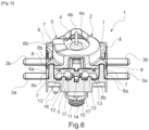
- thermal switch 1 is shown after crimping.
- Plastic crimping of the free ends of the crimping projections 7 is preferably carried out using gyroscopic crimping, but could also be carried out using radial riveting or orbital riveting, without departing from the scope of the present invention.
- the metal blades 3a, 3b are completely locked in position in the insulating housing 2, the positioning projections 12 and the parallelepiped lugs 7a of the crimping projections 7 making it possible to lock the blades 3a, 3b in their own planes, and the crimping of the free ends of the cylinders 7b of the crimping projections 7 making it possible to clamp the second housing part 6 on the first housing part 5 and thus to lock the blades 3a, 3b in the direction perpendicular to the plane of the blades 3a, 3b.
- the free ends of the crimping projections 7 are deformed and crushed, which allows the second housing part 6 to be locked on the first housing part 5.
- the crimping of the free ends of the crimping projections 7 thus makes it possible to guarantee the tamper-proof nature of the assembly of the thermal switch 1.
- the positioning projections 12 and crimping projections 7 of the insulating housing 2 thus allow the locking of the metal blades 3a, 3b and the closing of the insulating housing 2 in a single operation, which allows the assembly in a reliable and definitive manner of all the components of the thermal switch 1, in particular the metal blades 3a, 3b allowing the passage of current and the contact opening/closing mechanism 4.
- the present invention allows the thermal switch 1 to be disassembled during manufacturing, to improve the precision of the final product (more precise temperature), to increase the robustness of the product during handling by the installer and to reduce assembly costs and the number of components.
- Closing the insulating housing 2 by crimping also makes it possible to detect any possible tampering of the thermal switch 1 on site, since the crimping can no longer be repaired once destroyed.
- the rear part of the first housing part 5 further carries a screw thread 14 on which a nut 15 is mounted, and a foolproofing device 16 to allow the thermal switch 1 to be fixed to a support.
- a method of mounting the thermal switch 1 comprises the following steps: arranging the first and second pairs of blades 3a, 3b on the first housing part 5 so that the positioning projections 12 lock the position of each blade 3a, 3b in its own plane; arranging the contact opening/closing mechanism 4 and the second housing part 6 on the first housing part 5 so that each of the crimping projections 7 passes through the corresponding through hole 8; and performing a crimping on the free end of each of the crimping projections 7 emerging of the corresponding through hole 8 so as to block the position of the blades 3a, 3b in the direction perpendicular to the plane of the blades 3a, 3b.
Landscapes
- Physics & Mathematics (AREA)
- Electromagnetism (AREA)
- Thermally Actuated Switches (AREA)
Claims (12)
- - Thermischer Schalter (1), umfassend ein Isoliergehäuse (2), in dem mindestens ein Paar Metallstreifen (3a, 3b) und ein durch Temperatur betätigbarer Kontaktöffnungs-/-schließmechanismus (4) zwischen den Streifen (3a, 3b) des mindestens einen Streifenpaars (3a, 3b) angebracht sind, wobei das Isoliergehäuse (2) einen ersten Gehäuseteil (5) und einen zweiten Gehäuseteil (6) umfasst, dadurch gekennzeichnet, dass mindestens einer von dem ersten und zweiten Gehäuseteil (5, 6) für jeden Streifen (3a, 3b) des mindestens einen Streifenpaars (3a, 3b) mindestens einen Positionierungsvorsprung (12) trägt, der die Position des Streifens (3a, 3b) in seiner eigenen Ebene arretiert, wobei mindestens zwei Quetschvorsprünge (7) von mindestens einem von dem ersten und zweiten Gehäuseteil (5, 6) getragen werden, wobei der zweite Gehäuseteil (6) an dem ersten Gehäuseteil (5) so angebracht ist, dass jeder der mindestens zwei Quetschvorsprünge (7) ein entsprechendes Durchgangsloch (8) durchquert, das in dem anderen von dem ersten und zweiten Gehäuseteil (5, 6) ausgebildet ist, wobei das freie Ende von jedem der mindestens zwei Quetschvorsprünge (7) aus dem entsprechenden Durchgangsloch (8) austritt und so konfiguriert ist, dass es derart quetschbar ist, dass die Position der Streifen (3a, 3b) in der Richtung senkrecht zu den Ebenen der Streifen (3a, 3b) arretiert wird.
- - Thermischer Schalter (1) nach Anspruch 1, dadurch gekennzeichnet, dass die Höhe der mindestens zwei Quetschvorsprünge (7) größer ist als die Höhe der Positionierungsvorsprünge (12).
- - Thermischer Schalter (1) nach Anspruch 1 oder 2, dadurch gekennzeichnet, dass die mindestens zwei Quetschvorsprünge (7) auch Positionierungsvorsprünge sind.
- - Thermischer Schalter (1) nach Anspruch 3, dadurch gekennzeichnet, dass jeder Streifen (3a, 3b) des mindestens einen Streifenpaars (3a, 3b) durch drei Positionierungsvorsprünge (12) und einen Quetschvorsprung (7) arretiert wird.
- - Thermischer Schalter (1) nach einem der Ansprüche 1 bis 4, dadurch gekennzeichnet, dass an jedem Streifen (3a, 3b) des mindestens einen Streifenpaars (3a, 3b) Kerben (13) ausgebildet sind, wobei die Kerben (13) komplementär zu den Positionierungsvorsprüngen (12) für das Einsetzen der Streifen (3a, 3b) des mindestens einen Streifenpaars (3a, 3b) auf die Positionierungsvorsprünge (12) sind.
- - Thermischer Schalter (1) nach einem der Ansprüche 1 bis 5, dadurch gekennzeichnet, dass jeder Positionierungsvorsprung (12) ein quaderförmiger Stift ist und jeder Quetschvorsprung (7) entweder ein Zylinder (7b) oder ein quaderförmiger Stift (7a) ist, der von einem Zylinder (7b) überragt wird.
- - Thermischer Schalter (1) nach einem der Ansprüche 1 bis 6, dadurch gekennzeichnet, dass er zwei Streifenpaare (3a, 3b) mit demselben Kontaktöffnungs-/-schließmechanismus (4) umfasst.
- - Thermischer Schalter (1) nach einem der Ansprüche 1 bis 7, dadurch gekennzeichnet, dass der Kontaktöffnungs-/-schließmechanismus (4) ein temperaturverformbares wärmeempfindliches Element umfasst.
- - Thermischer Schalter (1) nach Anspruch 8, dadurch gekennzeichnet, dass der zweite Gehäuseteil (6) aus zwei Elementen (6a, 6b) besteht, zwischen denen das wärmeempfindliche Element arretiert ist.
- - Thermischer Schalter (1) nach Anspruch 8 oder 9, dadurch gekennzeichnet, dass das wärmeempfindliche Element entweder eine Bimetallscheibe oder eine wärmeempfindliche Kapillare (4b) ist, die mit einer Metallmembrananordnung (4a) verbunden ist.
- - Thermischer Schalter (1) nach einem der Ansprüche 1 bis 10, dadurch gekennzeichnet, dass das Isoliergehäuse (2) aus mindestens einem der Materialien Polybutylenterephthalat, PBT mit Glasfasercharge, und Polyamid 6, PA6, mit Glasfasercharge, hergestellt ist.
- - Verfahren zur Montage eines thermischen Schalters (1) nach einem der Ansprüche 1 bis 11, dadurch gekennzeichnet, dass es die folgenden Schritte umfasst:Anordnen des mindestens einen Streifenpaars (3a, 3b) auf dem ersten Gehäuseteil (5) derart, dass die Positionierungsvorsprünge (12) die Position jedes Streifens (3a, 3b) des mindestens einen Streifenpaars (3a, 3b) in seiner eigenen Ebene arretieren;Anordnen des Kontaktöffnungs-/- schließmechanismus (4) und des zweiten Gehäuseteils (6) auf dem ersten Gehäuseteil (5), so dass jeder der mindestens zwei Quetschvorsprünge (7) das entsprechende Durchgangsloch (8) durchquert; undDurchführen eines Quetschens an dem freien Ende jedes der mindestens zwei Quetschvorsprünge (7), die aus dem entsprechenden Durchgangsloch (8) austreten, um die Position der Streifen (3a, 3b) in der Richtung senkrecht zu den Ebenen der Streifen (3a, 3b) zu arretieren.
Priority Applications (1)
| Application Number | Priority Date | Filing Date | Title |
|---|---|---|---|
| RS20250214A RS66571B1 (sr) | 2020-11-17 | 2021-10-18 | Toplotni prekidač sa sklopom zaštićenim od manipulacije i postupak njegove montaže |
Applications Claiming Priority (2)
| Application Number | Priority Date | Filing Date | Title |
|---|---|---|---|
| FR2011767A FR3116376B1 (fr) | 2020-11-17 | 2020-11-17 | Interrupteur thermique a assemblage inviolable et son procede de montage |
| PCT/IB2021/059555 WO2022106931A1 (fr) | 2020-11-17 | 2021-10-18 | Interrupteur thermique a assemblage inviolable et son procede de montage |
Publications (3)
| Publication Number | Publication Date |
|---|---|
| EP4248472A1 EP4248472A1 (de) | 2023-09-27 |
| EP4248472B1 true EP4248472B1 (de) | 2024-12-04 |
| EP4248472C0 EP4248472C0 (de) | 2024-12-04 |
Family
ID=74758929
Family Applications (1)
| Application Number | Title | Priority Date | Filing Date |
|---|---|---|---|
| EP21805615.8A Active EP4248472B1 (de) | 2020-11-17 | 2021-10-18 | Thermischer schalter mit manipulationssicherer montage und montageverfahren dafür |
Country Status (6)
| Country | Link |
|---|---|
| EP (1) | EP4248472B1 (de) |
| ES (1) | ES3004945T3 (de) |
| FR (1) | FR3116376B1 (de) |
| PL (1) | PL4248472T3 (de) |
| RS (1) | RS66571B1 (de) |
| WO (1) | WO2022106931A1 (de) |
Family Cites Families (3)
| Publication number | Priority date | Publication date | Assignee | Title |
|---|---|---|---|---|
| DE102005060965B4 (de) * | 2005-06-28 | 2007-08-16 | Inter Control Hermann Köhler Elektrik GmbH & Co. KG | Thermische Sicherung mit Verfahren zu ihrer Herstellung |
| TW201735474A (zh) * | 2016-03-07 | 2017-10-01 | Otsuka Techno Corp | Usb插頭 |
| CN110867341A (zh) * | 2019-11-07 | 2020-03-06 | 太平洋电子(昆山)有限公司 | 一种接触式双金属片温控器 |
-
2020
- 2020-11-17 FR FR2011767A patent/FR3116376B1/fr active Active
-
2021
- 2021-10-18 PL PL21805615.8T patent/PL4248472T3/pl unknown
- 2021-10-18 EP EP21805615.8A patent/EP4248472B1/de active Active
- 2021-10-18 ES ES21805615T patent/ES3004945T3/es active Active
- 2021-10-18 WO PCT/IB2021/059555 patent/WO2022106931A1/fr not_active Ceased
- 2021-10-18 RS RS20250214A patent/RS66571B1/sr unknown
Also Published As
| Publication number | Publication date |
|---|---|
| ES3004945T3 (en) | 2025-03-13 |
| FR3116376B1 (fr) | 2022-10-07 |
| EP4248472A1 (de) | 2023-09-27 |
| FR3116376A1 (fr) | 2022-05-20 |
| PL4248472T3 (pl) | 2025-04-07 |
| RS66571B1 (sr) | 2025-03-31 |
| EP4248472C0 (de) | 2024-12-04 |
| WO2022106931A1 (fr) | 2022-05-27 |
Similar Documents
| Publication | Publication Date | Title |
|---|---|---|
| EP0366519B1 (de) | Durch den Zusammenbau von mehreren abnehmbaren Moduleinheiten hergestellte Sicherungsvorrichtung für Schaltgerät | |
| EP0174246B1 (de) | Verriegelungseinrichtung für die Bedienung eines elektrischen Apparates mit Handbedienung | |
| EP0309311A1 (de) | Überstromschalter | |
| FR2523796A1 (fr) | Dispositif de protection d'elements chauffants electriques immerges | |
| EP4248472B1 (de) | Thermischer schalter mit manipulationssicherer montage und montageverfahren dafür | |
| EP4248476B1 (de) | Thermischer schalter mit manipulationssicherer befestigung eines thermosensitiven elements und verfahren zu seiner montage | |
| EP2897154B1 (de) | Überspannungsableiter und selbstschützende elektrische Anordnung, die einen solchen Überspannungsableiter und einen Schutzschalter umfasst | |
| EP0758961B1 (de) | Zigarettenanzünderkörper insbesondere für kraftfahrzeuge | |
| EP4186084B1 (de) | Lichtbogenlöschkammer für eine elektrische schutzvorrichtung und elektrische schutzvorrichtung mit mindestens einer solchen lichtbogenlöschkammer | |
| EP0699556B1 (de) | Zigarettenanzünderkörper, insbesondere für Kraftfahrzeuge | |
| EP3651173B1 (de) | Schalteranordnung mit sicherer aufhängung für nothaltevorrichtung | |
| WO2017037371A1 (fr) | Appareil electromenager comportant une plaque chauffante alimentee par un thermostat equipe d'un coupe-circuit thermique | |
| EP3161850B1 (de) | Thermisch-magnetischer auslösungsmechanismus | |
| EP2200065B1 (de) | Elektromagnetische Auslösevorrichtung für Netzschutzschalter mit wenigstens zwei geschützten Polen | |
| EP1288978B1 (de) | Elektrisches Sicherheitsgerät mit verriegelbarem Rückstell- und Signalisierhebel | |
| FR2639146A1 (fr) | Appareil de commutation du type comprenant un module principal de commutation et un module de contacts auxiliaires amovible | |
| EP3644339B1 (de) | Gerät zur unterbrechung eines elektrischen stroms | |
| EP1708221B1 (de) | Mit einer Schmelzsicherung und einem aus Isoliermaterial hergestellten Ausschaltelement versehene Schutzvorichtung, und ihre Anwedung bei Überspannungsableitern | |
| EP2227818A2 (de) | Wärmesicherheitsvorrichtung | |
| EP1501112B1 (de) | Verbesserte magnetische Untereinheit und Schutzschalter der diese Untereinheit beinhaltet | |
| EP1708222B1 (de) | Mit einem pressverbunden und in der Ausschaltrichtung vorgespannten Schmelzelement versehene Schutzvorichtung, und ihre Anwedung bei Überspannungsableitern | |
| EP2743956B1 (de) | Gerät zur Stromunterbrechung, insbesondere Anschluss-Überlastschalter | |
| EP3629351A1 (de) | Betätigungssystem für elektrisches schaltgerät | |
| EP2575151A1 (de) | Verstärkung des Trennmechanismus eines multimodulären Elektrogerätes vom Typ Trennschalter | |
| FR2589293A1 (fr) | Dispositif de protection pour un moteur electrique, en particulier pour le moteur du compresseur d'une machine frigorifique |
Legal Events
| Date | Code | Title | Description |
|---|---|---|---|
| STAA | Information on the status of an ep patent application or granted ep patent |
Free format text: STATUS: UNKNOWN |
|
| STAA | Information on the status of an ep patent application or granted ep patent |
Free format text: STATUS: THE INTERNATIONAL PUBLICATION HAS BEEN MADE |
|
| PUAI | Public reference made under article 153(3) epc to a published international application that has entered the european phase |
Free format text: ORIGINAL CODE: 0009012 |
|
| STAA | Information on the status of an ep patent application or granted ep patent |
Free format text: STATUS: REQUEST FOR EXAMINATION WAS MADE |
|
| 17P | Request for examination filed |
Effective date: 20230330 |
|
| AK | Designated contracting states |
Kind code of ref document: A1 Designated state(s): AL AT BE BG CH CY CZ DE DK EE ES FI FR GB GR HR HU IE IS IT LI LT LU LV MC MK MT NL NO PL PT RO RS SE SI SK SM TR |
|
| DAV | Request for validation of the european patent (deleted) | ||
| DAX | Request for extension of the european patent (deleted) | ||
| GRAP | Despatch of communication of intention to grant a patent |
Free format text: ORIGINAL CODE: EPIDOSNIGR1 |
|
| STAA | Information on the status of an ep patent application or granted ep patent |
Free format text: STATUS: GRANT OF PATENT IS INTENDED |
|
| INTG | Intention to grant announced |
Effective date: 20240617 |
|
| GRAS | Grant fee paid |
Free format text: ORIGINAL CODE: EPIDOSNIGR3 |
|
| GRAA | (expected) grant |
Free format text: ORIGINAL CODE: 0009210 |
|
| STAA | Information on the status of an ep patent application or granted ep patent |
Free format text: STATUS: THE PATENT HAS BEEN GRANTED |
|
| AK | Designated contracting states |
Kind code of ref document: B1 Designated state(s): AL AT BE BG CH CY CZ DE DK EE ES FI FR GB GR HR HU IE IS IT LI LT LU LV MC MK MT NL NO PL PT RO RS SE SI SK SM TR |
|
| REG | Reference to a national code |
Ref country code: CH Ref legal event code: EP |
|
| REG | Reference to a national code |
Ref country code: DE Ref legal event code: R096 Ref document number: 602021023003 Country of ref document: DE |
|
| REG | Reference to a national code |
Ref country code: IE Ref legal event code: FG4D Free format text: LANGUAGE OF EP DOCUMENT: FRENCH |
|
| U01 | Request for unitary effect filed |
Effective date: 20250103 |
|
| REG | Reference to a national code |
Ref country code: ES Ref legal event code: FG2A Ref document number: 3004945 Country of ref document: ES Kind code of ref document: T3 Effective date: 20250313 |
|
| U07 | Unitary effect registered |
Designated state(s): AT BE BG DE DK EE FI FR IT LT LU LV MT NL PT RO SE SI Effective date: 20250217 |
|
| PG25 | Lapsed in a contracting state [announced via postgrant information from national office to epo] |
Ref country code: HR Free format text: LAPSE BECAUSE OF FAILURE TO SUBMIT A TRANSLATION OF THE DESCRIPTION OR TO PAY THE FEE WITHIN THE PRESCRIBED TIME-LIMIT Effective date: 20241204 |
|
| PG25 | Lapsed in a contracting state [announced via postgrant information from national office to epo] |
Ref country code: NO Free format text: LAPSE BECAUSE OF FAILURE TO SUBMIT A TRANSLATION OF THE DESCRIPTION OR TO PAY THE FEE WITHIN THE PRESCRIBED TIME-LIMIT Effective date: 20250304 |
|
| PG25 | Lapsed in a contracting state [announced via postgrant information from national office to epo] |
Ref country code: GR Free format text: LAPSE BECAUSE OF FAILURE TO SUBMIT A TRANSLATION OF THE DESCRIPTION OR TO PAY THE FEE WITHIN THE PRESCRIBED TIME-LIMIT Effective date: 20250305 |
|
| PG25 | Lapsed in a contracting state [announced via postgrant information from national office to epo] |
Ref country code: SM Free format text: LAPSE BECAUSE OF FAILURE TO SUBMIT A TRANSLATION OF THE DESCRIPTION OR TO PAY THE FEE WITHIN THE PRESCRIBED TIME-LIMIT Effective date: 20241204 |
|
| PG25 | Lapsed in a contracting state [announced via postgrant information from national office to epo] |
Ref country code: IS Free format text: LAPSE BECAUSE OF FAILURE TO SUBMIT A TRANSLATION OF THE DESCRIPTION OR TO PAY THE FEE WITHIN THE PRESCRIBED TIME-LIMIT Effective date: 20250404 |
|
| PG25 | Lapsed in a contracting state [announced via postgrant information from national office to epo] |
Ref country code: SK Free format text: LAPSE BECAUSE OF FAILURE TO SUBMIT A TRANSLATION OF THE DESCRIPTION OR TO PAY THE FEE WITHIN THE PRESCRIBED TIME-LIMIT Effective date: 20241204 |
|
| PLBE | No opposition filed within time limit |
Free format text: ORIGINAL CODE: 0009261 |
|
| STAA | Information on the status of an ep patent application or granted ep patent |
Free format text: STATUS: NO OPPOSITION FILED WITHIN TIME LIMIT |
|
| 26N | No opposition filed |
Effective date: 20250905 |
|
| U20 | Renewal fee for the european patent with unitary effect paid |
Year of fee payment: 5 Effective date: 20251030 |
|
| PGFP | Annual fee paid to national office [announced via postgrant information from national office to epo] |
Ref country code: GB Payment date: 20251014 Year of fee payment: 5 |
|
| PGFP | Annual fee paid to national office [announced via postgrant information from national office to epo] |
Ref country code: TR Payment date: 20251013 Year of fee payment: 5 |
|
| PGFP | Annual fee paid to national office [announced via postgrant information from national office to epo] |
Ref country code: CZ Payment date: 20251008 Year of fee payment: 5 |
|
| PGFP | Annual fee paid to national office [announced via postgrant information from national office to epo] |
Ref country code: PL Payment date: 20251006 Year of fee payment: 5 |
|
| PGFP | Annual fee paid to national office [announced via postgrant information from national office to epo] |
Ref country code: RS Payment date: 20251007 Year of fee payment: 5 |
|
| PGFP | Annual fee paid to national office [announced via postgrant information from national office to epo] |
Ref country code: ES Payment date: 20251107 Year of fee payment: 5 |