EP4248472B1 - Thermal switch with tamper-proof assembly and its mounting method - Google Patents
Thermal switch with tamper-proof assembly and its mounting method Download PDFInfo
- Publication number
- EP4248472B1 EP4248472B1 EP21805615.8A EP21805615A EP4248472B1 EP 4248472 B1 EP4248472 B1 EP 4248472B1 EP 21805615 A EP21805615 A EP 21805615A EP 4248472 B1 EP4248472 B1 EP 4248472B1
- Authority
- EP
- European Patent Office
- Prior art keywords
- blades
- crimping
- thermal switch
- projections
- housing part
- Prior art date
- Legal status (The legal status is an assumption and is not a legal conclusion. Google has not performed a legal analysis and makes no representation as to the accuracy of the status listed.)
- Active
Links
Images


Classifications
-
- H—ELECTRICITY
- H01—ELECTRIC ELEMENTS
- H01H—ELECTRIC SWITCHES; RELAYS; SELECTORS; EMERGENCY PROTECTIVE DEVICES
- H01H37/00—Thermally-actuated switches
- H01H37/02—Details
- H01H37/04—Bases; Housings; Mountings
-
- H—ELECTRICITY
- H01—ELECTRIC ELEMENTS
- H01H—ELECTRIC SWITCHES; RELAYS; SELECTORS; EMERGENCY PROTECTIVE DEVICES
- H01H1/00—Contacts
- H01H1/58—Electric connections to or between contacts; Terminals
-
- H—ELECTRICITY
- H01—ELECTRIC ELEMENTS
- H01H—ELECTRIC SWITCHES; RELAYS; SELECTORS; EMERGENCY PROTECTIVE DEVICES
- H01H1/00—Contacts
- H01H1/12—Contacts characterised by the manner in which co-operating contacts engage
- H01H1/14—Contacts characterised by the manner in which co-operating contacts engage by abutting
- H01H1/20—Bridging contacts
- H01H1/2025—Bridging contacts comprising two-parallel bridges
-
- H—ELECTRICITY
- H01—ELECTRIC ELEMENTS
- H01H—ELECTRIC SWITCHES; RELAYS; SELECTORS; EMERGENCY PROTECTIVE DEVICES
- H01H37/00—Thermally-actuated switches
- H01H37/02—Details
- H01H37/64—Contacts
Definitions
- the present invention relates to the field of thermal switches, and in particular relates to a thermal switch with tamper-proof assembly and to its assembly method.
- Thermal switches also called temperature-actuated switches, electromechanical microswitches, or thermal circuit breakers
- bimetallic switches are safety devices that mechanically trigger a contact, which opens a protected electrical circuit, when the thermal switch heats up.
- Thermal switches generally consist of an insulating housing in which are mounted at least one pair of metal blades connected to a protected electrical circuit and a contact opening/closing mechanism between the blades of the at least one pair of blades actuated by temperature such as a heat-sensitive bimetallic disk or metal membranes connected to a heat-sensitive capillary.
- the protected electrical circuit may, for example, be part of a water heater or any other device such as an electric heating device for private or collective use.
- the present invention aims to solve the drawbacks of the prior art by proposing a thermal switch comprising an insulating housing in which are mounted at least one pair of metal blades and a mechanism opening/closing contact between the blades of the at least one temperature-actuable blade pair, the blades being locked in position in their own planes by means of positioning projections and being locked in position in the direction perpendicular to the planes of the blades by means of at least two crimping projections, the crimping of the at least two crimping projections thereby providing a tamper-proof assembly of the thermal switch, and also enabling a reduction in costs, since no additional components are required to ensure the tamper-proofness of the thermal switch according to the present invention.
- the present invention therefore relates to a thermal switch comprising an insulating housing in which are mounted at least one pair of metal blades and a mechanism for opening/closing contact between the blades of the at least one pair of blades actuable by temperature, characterized in that the insulating housing comprises a first housing part and a second housing part, at least one of the first and second housing parts carrying, for each blade of the at least one pair of blades, at least one positioning projection which blocks the position of said blade in its own plane, at least two crimping projections being carried by at least one of the first and second housing parts, the second housing part being mounted on the first housing part such that each of the at least two crimping projections passes through a corresponding through hole formed in the other of the first and second housing parts, the free end of each of the at least two crimping projections emerging from the corresponding through hole and being configured to be crimped so as to block the position of the blades in the direction perpendicular to the blade plans.
- the opening of a contact between the two blades of the same pair of blades when the contact opening/closing mechanism is actuated during an excessive temperature makes it possible to protect users from an excessive temperature rise of the electric water heater.
- the metal blades of the at least one pair of blades are completely locked in position in the insulating housing, the positioning projections making it possible to lock the blades in their own planes and the crimping of the free ends of the at least two crimping projections making it possible to clamp the second housing part on the first housing part and thus to lock the blades in the direction perpendicular to the planes of the blades.
- metal blades can be arranged in the same plane or in different parallel planes.
- Crimping the free ends of the at least two crimp projections also helps ensure the tamper-proof nature of the thermal switch assembly.
- the positioning and crimping projections of the insulating housing allow the locking of the metal blades and the closing of the insulating housing in a single operation, which allows the reliable and definitive assembly of all the components of the thermal switch, in particular the metal blades allowing the passage of current and the contact opening/closing mechanism.
- the present invention thus makes it possible to reduce the number of operations and components during assembly, to avoid waste (the thermal switch being removable and repairable up to the last crimping operation) and to guarantee the operation of the thermal switch without drift during use.
- the present invention allows the product to be disassembled during manufacturing, to improve the precision of the final product (more precise temperature), to increase the robustness of the product during handling by the installer and to reduce assembly costs and the number of components.
- Closing the insulating housing by crimping keeps all the components in place and also makes it possible to detect any possible disassembly of the thermal switch by customers.
- the insulating housing has two crimping projections, these are preferably diametrically opposed.
- the thermal switch has a metal blade crimping projection.
- the thermal switch comprises four crimping projections distributed around the contact opening/closing mechanism.
- the present invention has the following advantages: fewer parts compared to existing solutions (e.g. four fewer metal rivets); more advantageous in terms of logistics, assembly and production costs due to the reduced number of parts; in addition, it allows detection of tampering with the thermal switch, since the crimping can no longer be repaired once destroyed.
- the height of the at least two crimping projections is greater than that of the positioning projections.
- the crimping projections of the insulating housing are higher to allow stacking of the other components of the thermal switch, and to finally crimp the free ends of the crimping projections opening out of the corresponding through holes of the insulating housing, so as to assemble the first and second housing parts together to block the other components of the thermal switch inside the insulating housing.
- the at least two projections of Crimps are also positioning projections.
- the crimping projections allow both the locking of the blades in their own planes and the locking of the blades in the direction perpendicular to the planes of the blades.
- the insulating housing could comprise a single projection per metal blade, said single projection serving both as a positioning projection and as a crimping projection, said single projection being able for example to pass through in an adjusted manner an orifice formed in the thickness of the corresponding blade then pass through the corresponding through hole of the insulating housing to allow the crimping of its free end.
- each blade of the at least one pair of blades is blocked by three positioning projections and a crimping projection.
- each blade is locked in its own plane by the three positioning projections and the crimping projection, and is locked in the direction perpendicular to its own plane when the free ends of the crimping projections of the insulating housing are crimped.
- notches are formed on each blade of the at least one pair of blades, said notches being complementary to the positioning projections for inserting the blades of the at least one pair of blades on the positioning projections.
- Each notch can be a side notch or a central notch formed in the thickness of the corresponding blade.
- a notch is also formed on the blade for insertion of the blade onto the crimping projection.
- each positioning projection is a parallelepiped lug
- each crimping projection is one of a cylinder and a parallelepiped lug surmounted by a cylinder.
- the notches of the blades are inserted on the parallelepiped lugs of the projections so as to allow the blades to be locked in their own planes.
- the cylinders of the crimping projections pass through the corresponding through holes formed in the insulating housing, and then the free ends of the cylinders are crimped.
- the thermal switch consists of two pairs of blades having the same contact opening/closing mechanism.
- the same contact opening/closing mechanism allows the contact between the two blades of the first pair of blades and the contact between the two blades of the second pair of blades to be opened simultaneously when the temperature becomes excessive.
- Each pair of blades can, for example, be connected to one of the power supply phases of the electrical network.
- the contact opening/closing mechanism comprises a heat-sensitive element deformable by temperature.
- the heat-sensitive element is configured to deform with temperature variations, said deformation causing the contact between the two blades of each pair of blades to open when the temperature exceeds a predefined temperature threshold.
- the second housing part consists of two elements between which the heat-sensitive element is blocked.
- the heat-sensitive element is locked in position between the two elements of the second housing part when crimping the free ends of the crimping projections, which improves the accuracy of the final product (more precise triggering temperature).
- the heat-sensitive element is one of a bimetallic disk and a heat-sensitive capillary connected to a metal membrane assembly.
- the heat-sensitive capillary is connected to a metal membrane assembly, preferably consisting of an outer circular metal membrane and an inner circular metal membrane, a liquid being present between the outer and inner membranes, the passage of said liquid into vapor phase or the expansion of said liquid when the temperature exceeds a certain threshold causing the deformation of the outer and inner membranes, which causes the opening of the contact between the two blades of each pair of blades.
- a metal membrane assembly preferably consisting of an outer circular metal membrane and an inner circular metal membrane, a liquid being present between the outer and inner membranes, the passage of said liquid into vapor phase or the expansion of said liquid when the temperature exceeds a certain threshold causing the deformation of the outer and inner membranes, which causes the opening of the contact between the two blades of each pair of blades.
- the external and internal membranes of the metal membrane assembly can, for example, be made of steel (stainless, ferritic or low alloy).
- the heat-sensitive capillary may, for example, be of the twist or hairpin type (e.g., made of copper), the interior of the capillary being in fluid communication with the interior of the metal membrane assembly, the metal membrane assembly and the capillary thus forming a thermostatic train.
- the insulating housing is made of at least at least one material from poly(butylene terephthalate), PBT, filled with glass fibers and polyamide 6, PA6, filled with glass fibers.
- the material used for the insulating housing has good fire resistance and is suitable for plastic crimping of the free ends of the crimping projections.
- the present invention also relates to a method for mounting a thermal switch as described above, characterized in that it comprises the following steps: arranging the at least one pair of blades on the first housing part so that the positioning projections lock the position of each blade of the at least one pair of blades in its own plane; arranging the contact opening/closing mechanism and the second housing part on the first housing part so that each of the at least two crimping projections passes through the corresponding through hole; and performing a crimping on the free end of each of the at least two crimping projections emerging from the corresponding through hole so as to lock the position of the blades in the direction perpendicular to the planes of the blades.
- the plastic crimping of the free ends of the crimping projections is preferably carried out using gyroscopic crimping, but could also be carried out using radial riveting or orbital riveting, without departing from the scope of the present invention.
- crimping could also be done by ultrasound.
- this technique is less preferred, since it poses temperature problems (too high temperature therefore approximate crimping due to the elastic return of the material).
- the thermal switch 1 comprises an insulating housing 2 in which are mounted first 3a and second 3b pairs of metal blades and a contact opening/closing mechanism 4 actuated by temperature.
- thermal switch 1 could also comprise a single pair of blades or at least three pairs of blades, without departing from the scope of the present invention.
- the blades of the first and second pairs of blades 3a, 3b are arranged in the same plane, but could also be arranged in different parallel planes, without departing from the scope of the present invention.
- the contact opening/closing mechanism 4 is configured to simultaneously open/close a contact between the two blades of the first pair of blades 3a and a contact between the two blades of the second pair of blades 3b depending on the temperature.
- the contact opening/closing mechanism 4 comprises a metal membrane assembly 4a connected to a thermosensitive capillary 4b of the twist type, so as to form a thermostatic train for the thermal switch 1.
- thermosensitive capillary 4b could also be of the pin type or other, without departing from the scope of the present invention.
- heat-sensitive capillary 4b and the metal membrane assembly 4a could also be replaced by a heat-sensitive bimetallic disk, without departing from the scope of the present invention.
- the insulating housing 2 comprises a first housing part 5 and a second housing part 6 between which the two pairs of blades 3a, 3b are blocked.
- the second housing part 6 consists of a first lower element 6a and a second upper element 6b between which the metal membrane assembly 4a is locked in position, the second upper element 6b matching the upper part of the metal membrane assembly 4a.
- the first and second housing parts 5, 6 are assembled together by crimping the free ends of four crimping projections 7 formed on the first housing part 5 and passing through corresponding through holes 8 formed on the second housing part 6, so as to block the blades 3a, 3b and the opening/closing mechanism 4 inside the insulating housing 2.
- the crimping projections 7 could also be formed on the second housing part 6 and the through holes 8 formed on the first housing part 5, the crimping then being carried out at the lower part of the thermal switch 1, without departing from the scope of the present invention.
- some crimping projections 7 could be formed on the first housing part 5 and others crimping projections 7 formed on the second housing part 6, without departing from the scope of the present invention.
- the four crimping projections 7 are distributed around the metal membrane assembly 4a, arranged respectively at the four corners of the insulating housing 2.
- thermal switch 1 could also comprise only two diametrically opposed crimping projections 7, without departing from the scope of the present invention. Furthermore, the thermal switch 1 could also comprise three or at least five crimping projections 7, without departing from the scope of the present invention.
- Crimping the free ends of the crimping projections 7 thus makes it possible to make the assembly of the thermal switch 1 tamper-proof.
- the insulating housing 2 is made of at least one material from among polybutylene terephthalate (PBT) filled with glass fibers and polyamide 6 (PA6) filled with glass fibers.
- PBT polybutylene terephthalate
- PA6 polyamide 6
- the opening of the contact between the two blades of the same pair of blades 3a, 3b when the contact opening/closing mechanism 4 is actuated as soon as the temperature exceeds a certain temperature threshold makes it possible to protect users against an excessive rise in temperature of the electric water heater.
- Each pair of blades 3a, 3b can, for example, be connected to one of the power supply phases of the electrical network.
- the metal membrane assembly 4a consists of an external circular metal membrane (visible on the [ Fig.2 ]) and an internal circular metal membrane (not visible on the [ Fig.2 ]).
- the outer and inner membranes of the metal membrane assembly 4a may, for example, be made of steel (stainless, ferritic or low alloy).
- the interior of the capillary 4b is in fluid communication with the interior of the metal membrane assembly 4a, a liquid being present between the outer and inner membranes of the metal membrane assembly 4a and in the capillary 4b, the passage of said liquid into the vapor phase or the expansion of said liquid when the temperature exceeds a certain predefined threshold causing the deformation of the metal membrane assembly 4a in the thermal switch 1.
- a metal strip 9 is arranged under the two blades 3b of the pair, a compression spring 10 arranged under the metal blade 9 causing the metal blade 9 to come into contact with the two blades 3b and thus establishing contact between the two blades 3b of the pair, such that the contact is normally closed.
- the contact opening/closing mechanism 4 further comprises a vertical slide 11 arranged between the lower part of the metal membrane assembly 4a and the upper part of the two metal strips 9.
- the deformation of the metal membrane assembly 4a when the temperature exceeds the predefined temperature threshold causes the vertical slide 11 to move downwards and thus the two metal strips 9 to move downwards, which causes the contact between the strips 3a, 3b of the same pair to open.
- the contact is closed between the blades 3a, 3b of the same pair, and, when the metal membrane assembly 4a is curved downwards (temperature greater than or equal to the temperature threshold), the contact is open between the blades 3a, 3b of the same pair, which makes it possible to protect the electrical circuit connected to the blades 3a, 3b.
- a press by the user on the vertical slide 11 at the rear of the thermal switch 1 is necessary to bring the metal strips 9 back into contact with the blades 9a, 9b and thus close the contacts.
- first housing part 5 of the insulating housing 2 is represented thereon, on which the first and second pairs of blades 3a, 3b are arranged.
- the first housing part 5 For each of the four metal blades 3a, 3b, the first housing part 5 carries three positioning projections 12 and a crimping projection 7.
- positioning projections 12 could also be carried by the second housing part 6, without departing from the scope of the present invention.
- the insulating housing 2 could carry any number of positioning projections 12, without departing from the scope of the present invention.
- Each of the four blades 3a, 3b has four lateral notches 13 complementary to the corresponding positioning projections 12 and crimping projections 7 for the insertion of the blade 3a, 3b on the corresponding positioning projections 12 and crimping projections 7, such that each blade 3a, 3b is locked in position in its own plane.
- the crimping projections 7 thus also serve as positioning projections for the blades 3a, 3b.
- At least one of the notches 13 could also be a central notch formed in the thickness of the blade 3a, 3b and crossed by one of the projections 12, 7, without departing from the scope of the present invention.
- the insulating housing 2 could also comprise a single projection per metal blade 3a, 3b, said single projection serving both as a positioning projection and as a crimping projection, said single projection being able for example to pass through in an adjusted manner an orifice formed in the thickness of the corresponding blade 3a, 3b then pass through the corresponding through hole 8 of the second housing part 6 to allow the crimping of its free end.
- the height of the crimping projections 7 is greater than that of the positioning projections 12.
- Each positioning projection 12 is in the form of a parallelepiped lug
- each crimping projection 7 consists of a parallelepiped lug 7a surmounted by a cylinder 7b.
- thermal switch 1 is represented there before crimping.
- the first lower member 6a of the second housing part 6 is mounted on the first housing part 5 such that each of the crimping projections 7 passes through a corresponding through hole 8a formed in the first lower member 6a of the second housing part 6.
- the metal membrane assembly 4a is mounted on the first lower member 6a of the second housing part 6, and then the second upper member 6b of the second housing part 6 is mounted on the first lower member 6a of the second housing part 6 such that each of the crimping projections 7 passes through a corresponding through hole 8b formed in the second upper member 6b of the second housing part 6, the free end of each of the crimping projections 7 emerging from the corresponding through hole 8b and being configured to be crimped so as to lock the position of the blades 3a, 3b in the direction perpendicular to the plane of the blades 3a, 3b.
- thermal switch 1 is shown after crimping.
- Plastic crimping of the free ends of the crimping projections 7 is preferably carried out using gyroscopic crimping, but could also be carried out using radial riveting or orbital riveting, without departing from the scope of the present invention.
- the metal blades 3a, 3b are completely locked in position in the insulating housing 2, the positioning projections 12 and the parallelepiped lugs 7a of the crimping projections 7 making it possible to lock the blades 3a, 3b in their own planes, and the crimping of the free ends of the cylinders 7b of the crimping projections 7 making it possible to clamp the second housing part 6 on the first housing part 5 and thus to lock the blades 3a, 3b in the direction perpendicular to the plane of the blades 3a, 3b.
- the free ends of the crimping projections 7 are deformed and crushed, which allows the second housing part 6 to be locked on the first housing part 5.
- the crimping of the free ends of the crimping projections 7 thus makes it possible to guarantee the tamper-proof nature of the assembly of the thermal switch 1.
- the positioning projections 12 and crimping projections 7 of the insulating housing 2 thus allow the locking of the metal blades 3a, 3b and the closing of the insulating housing 2 in a single operation, which allows the assembly in a reliable and definitive manner of all the components of the thermal switch 1, in particular the metal blades 3a, 3b allowing the passage of current and the contact opening/closing mechanism 4.
- the present invention allows the thermal switch 1 to be disassembled during manufacturing, to improve the precision of the final product (more precise temperature), to increase the robustness of the product during handling by the installer and to reduce assembly costs and the number of components.
- Closing the insulating housing 2 by crimping also makes it possible to detect any possible tampering of the thermal switch 1 on site, since the crimping can no longer be repaired once destroyed.
- the rear part of the first housing part 5 further carries a screw thread 14 on which a nut 15 is mounted, and a foolproofing device 16 to allow the thermal switch 1 to be fixed to a support.
- a method of mounting the thermal switch 1 comprises the following steps: arranging the first and second pairs of blades 3a, 3b on the first housing part 5 so that the positioning projections 12 lock the position of each blade 3a, 3b in its own plane; arranging the contact opening/closing mechanism 4 and the second housing part 6 on the first housing part 5 so that each of the crimping projections 7 passes through the corresponding through hole 8; and performing a crimping on the free end of each of the crimping projections 7 emerging of the corresponding through hole 8 so as to block the position of the blades 3a, 3b in the direction perpendicular to the plane of the blades 3a, 3b.
Landscapes
- Physics & Mathematics (AREA)
- Electromagnetism (AREA)
- Thermally Actuated Switches (AREA)
Description
La présente invention concerne le domaine des interrupteurs thermiques, et porte en particulier sur un interrupteur thermique à assemblage inviolable et sur son procédé de montage.The present invention relates to the field of thermal switches, and in particular relates to a thermal switch with tamper-proof assembly and to its assembly method.
Les interrupteurs thermiques (également appelés interrupteurs actionnés par la température, microrupteurs électromécaniques ou coupe-circuits thermiques), tels que les interrupteurs de type bilame, sont des systèmes de sécurité permettant de déclencher mécaniquement un contact, qui ouvre un circuit électrique protégé, lors d'un échauffement de l'interrupteur thermique.Thermal switches (also called temperature-actuated switches, electromechanical microswitches, or thermal circuit breakers), such as bimetallic switches, are safety devices that mechanically trigger a contact, which opens a protected electrical circuit, when the thermal switch heats up.
Les interrupteurs thermiques sont généralement constitués d'un boîtier isolant dans lequel sont montés au moins une paire de lames métalliques reliées à un circuit électrique protégé et un mécanisme d'ouverture/fermeture de contact entre les lames de l'au moins une paire de lames actionnable par la température tel qu'un disque bimétallique thermosensible ou bien des membranes métalliques reliées à un capillaire thermosensible. Le circuit électrique protégé peut, par exemple, faire partie d'un chauffe-eau ou tout autre appareil tel qu'un appareil de chauffage électrique à usage particulier ou collectif.Thermal switches generally consist of an insulating housing in which are mounted at least one pair of metal blades connected to a protected electrical circuit and a contact opening/closing mechanism between the blades of the at least one pair of blades actuated by temperature such as a heat-sensitive bimetallic disk or metal membranes connected to a heat-sensitive capillary. The protected electrical circuit may, for example, be part of a water heater or any other device such as an electric heating device for private or collective use.
Les différentes solutions existantes pour le blocage des lames métalliques dans le boîtier isolant de l'interrupteur thermique sont les suivantes : le rivetage des lames métalliques, cependant cette solution implique l'utilisation de composants supplémentaires et nécessite l'ajout d'un composant pour garantir l'inviolabilité de l'interrupteur thermique ; le surmoulage des lames métalliques, cependant cette solution implique un coût et un investissement importants ; la fermeture du boîtier isolant à l'aide de vis, cependant cette solution implique l'utilisation de composants supplémentaires et nécessite l'ajout d'un composant pour garantir l'inviolabilité de l'interrupteur thermique ; et la fermeture du boîtier isolant à l'aide de clips en matière plastique, cependant cette solution ne permet pas de rendre indémontable l'interrupteur thermique avec un jeux mécanique minimal ou nul. Il n'existe donc pas de solution permettant de garantir un assemblage inviolable de l'interrupteur thermique.The various existing solutions for locking the metal blades in the insulating housing of the thermal switch are as follows: riveting the metal blades, however this solution involves the use of additional components and requires the addition of a component to ensure the tamper-proofness of the thermal switch; overmolding the metal blades, however this solution involves a significant cost and investment; closing the insulating housing using screws, however this solution involves the use of additional components and requires the addition of a component to ensure the tamper-proofness of the thermal switch; and closing the insulating housing using plastic clips, however this solution does not make the thermal switch undisassemblable with minimal or no mechanical play. There is therefore no solution to guarantee a tamper-proof assembly of the thermal switch.
La présente invention vise à résoudre les inconvénients de l'état antérieur de la technique en proposant un interrupteur thermique comprenant un boîtier isolant dans lequel sont montés au moins une paire de lames métalliques et un mécanisme d'ouverture/fermeture de contact entre les lames de l'au moins une paire de lames actionnable par la température, les lames étant bloquées en position dans leurs propres plans à l'aide de saillies de positionnement et étant bloquées en position dans la direction perpendiculaire aux plans des lames à l'aide d'au moins deux saillies de sertissage, le sertissage des au moins deux saillies de sertissage permettant ainsi d'obtenir un assemblage inviolable de l'interrupteur thermique, et permettant également une diminution des coûts, étant donné qu'aucun composant supplémentaire n'est nécessaire pour garantir l'inviolabilité de l'interrupteur thermique selon la présente invention.The present invention aims to solve the drawbacks of the prior art by proposing a thermal switch comprising an insulating housing in which are mounted at least one pair of metal blades and a mechanism opening/closing contact between the blades of the at least one temperature-actuable blade pair, the blades being locked in position in their own planes by means of positioning projections and being locked in position in the direction perpendicular to the planes of the blades by means of at least two crimping projections, the crimping of the at least two crimping projections thereby providing a tamper-proof assembly of the thermal switch, and also enabling a reduction in costs, since no additional components are required to ensure the tamper-proofness of the thermal switch according to the present invention.
La présente invention a donc pour objet un interrupteur thermique comprenant un boîtier isolant dans lequel sont montés au moins une paire de lames métalliques et un mécanisme d'ouverture/fermeture de contact entre les lames de l'au moins une paire de lames actionnable par la température, caractérisé par le fait que le boîtier isolant comprend une première partie de boîtier et une seconde partie de boîtier, au moins l'une des première et seconde parties de boîtier portant, pour chaque lame de l'au moins une paire de lames, au moins une saillie de positionnement qui bloque la position de ladite lame dans son propre plan, au moins deux saillies de sertissage étant portées par au moins l'une des première et seconde parties de boîtier, la seconde partie de boîtier étant montée sur la première partie de boîtier de telle sorte que chacune des au moins deux saillies de sertissage traverse un trou traversant correspondant formé dans l'autre des première et seconde parties de boîtier, l'extrémité libre de chacune des au moins deux saillies de sertissage débouchant du trou traversant correspondant et étant configurée pour être sertie de manière à bloquer la position des lames dans la direction perpendiculaire aux plans des lames.The present invention therefore relates to a thermal switch comprising an insulating housing in which are mounted at least one pair of metal blades and a mechanism for opening/closing contact between the blades of the at least one pair of blades actuable by temperature, characterized in that the insulating housing comprises a first housing part and a second housing part, at least one of the first and second housing parts carrying, for each blade of the at least one pair of blades, at least one positioning projection which blocks the position of said blade in its own plane, at least two crimping projections being carried by at least one of the first and second housing parts, the second housing part being mounted on the first housing part such that each of the at least two crimping projections passes through a corresponding through hole formed in the other of the first and second housing parts, the free end of each of the at least two crimping projections emerging from the corresponding through hole and being configured to be crimped so as to block the position of the blades in the direction perpendicular to the blade plans.
Dans le cas où l'au moins une paire de lames de l'interrupteur thermique selon la présente invention est reliée à un circuit électrique d'un chauffe-eau électrique, l'ouverture d'un contact entre les deux lames d'une même paire de lames lorsque le mécanisme d'ouverture/fermeture de contact est actionné lors d'une température excessive permet de protéger les utilisateurs vis-à-vis d'une montée en température excessive du chauffe-eau électrique.In the case where the at least one pair of blades of the thermal switch according to the present invention is connected to an electrical circuit of an electric water heater, the opening of a contact between the two blades of the same pair of blades when the contact opening/closing mechanism is actuated during an excessive temperature makes it possible to protect users from an excessive temperature rise of the electric water heater.
Ainsi, les lames métalliques de l'au moins une paire de lames sont complètement bloquées en position dans le boîtier isolant, les saillies de positionnement permettant de bloquer les lames dans leurs propres plans et le sertissage des extrémités libres des au moins deux saillies de sertissage permettant de brider la seconde partie de boîtier sur la première partie de boîtier et ainsi de bloquer les lames dans la direction perpendiculaire aux plans des lames.Thus, the metal blades of the at least one pair of blades are completely locked in position in the insulating housing, the positioning projections making it possible to lock the blades in their own planes and the crimping of the free ends of the at least two crimping projections making it possible to clamp the second housing part on the first housing part and thus to lock the blades in the direction perpendicular to the planes of the blades.
Il est à noter que les lames métalliques peuvent être disposées dans un même plan ou dans des plans parallèles différents.It should be noted that the metal blades can be arranged in the same plane or in different parallel planes.
Le sertissage des extrémités libres des au moins deux saillies de sertissage permet également de garantir l'inviolabilité de l'assemblage de l'interrupteur thermique.Crimping the free ends of the at least two crimp projections also helps ensure the tamper-proof nature of the thermal switch assembly.
Ainsi, les saillies de positionnement et de sertissage du boîtier isolant permettent le blocage des lames métalliques et la fermeture du boîtier isolant en une seule opération, ce qui permet d'assembler de manière fiable et définitive l'ensemble des composants de l'interrupteur thermique, notamment les lames métalliques permettant le passage du courant et le mécanisme d'ouverture/fermeture de contact.Thus, the positioning and crimping projections of the insulating housing allow the locking of the metal blades and the closing of the insulating housing in a single operation, which allows the reliable and definitive assembly of all the components of the thermal switch, in particular the metal blades allowing the passage of current and the contact opening/closing mechanism.
La présente invention permet ainsi de réduire le nombre d'opérations et de composants lors du montage, d'éviter les rebuts (l'interrupteur thermique étant démontable et réparable jusqu'à la dernière opération de sertissage) et de garantir le fonctionnement de l'interrupteur thermique sans dérive lors de l'utilisation.The present invention thus makes it possible to reduce the number of operations and components during assembly, to avoid waste (the thermal switch being removable and repairable up to the last crimping operation) and to guarantee the operation of the thermal switch without drift during use.
Ainsi, la présente invention permet au produit d'être démontable lors de la fabrication, d'améliorer la précision du produit final (température plus précise), d'augmenter la robustesse du produit lors des manipulations par l'installeur et de réduire les coûts de montage et le nombre de composants.Thus, the present invention allows the product to be disassembled during manufacturing, to improve the precision of the final product (more precise temperature), to increase the robustness of the product during handling by the installer and to reduce assembly costs and the number of components.
La fermeture du boîtier isolant par sertissage permet de maintenir l'ensemble des composants en place et permet également de détecter un éventuel démontage de l'interrupteur thermique en clientèle.Closing the insulating housing by crimping keeps all the components in place and also makes it possible to detect any possible disassembly of the thermal switch by customers.
Lorsque le boîtier isolant comporte deux saillies de sertissage, celles-ci sont, de préférence, diamétralement opposées.When the insulating housing has two crimping projections, these are preferably diametrically opposed.
De préférence, l'interrupteur thermique comporte une saillie de sertissage par lame métallique.Preferably, the thermal switch has a metal blade crimping projection.
De manière davantage préférée, l'interrupteur thermique comporte quatre saillies de sertissage réparties autour du mécanisme d'ouverture/fermeture de contact.More preferably, the thermal switch comprises four crimping projections distributed around the contact opening/closing mechanism.
La présente invention possède les avantages suivants : moins de pièces vis-à-vis des solutions existantes (par exemple, quatre rivets métalliques en moins) ; plus avantageux en termes logistiques, de coûts de montage et de production du fait du nombre réduit de pièces ; permet en plus une détection d'effraction de l'interrupteur thermique, car le sertissage ne peut plus être remis en état une fois détruit.The present invention has the following advantages: fewer parts compared to existing solutions (e.g. four fewer metal rivets); more advantageous in terms of logistics, assembly and production costs due to the reduced number of parts; in addition, it allows detection of tampering with the thermal switch, since the crimping can no longer be repaired once destroyed.
Selon une caractéristique particulière de l'invention, la hauteur des au moins deux saillies de sertissage est supérieure à celle des saillies de positionnement.According to a particular characteristic of the invention, the height of the at least two crimping projections is greater than that of the positioning projections.
Ainsi, les saillies de sertissage du boîtier isolant sont plus hautes pour permettre l'empilement des autres composants de l'interrupteur thermique, et pour au final sertir les extrémités libres des saillies de sertissage débouchant des trous traversants correspondants du boîtier isolant, de manière à assembler les première et seconde parties de boîtier entre elles pour bloquer les autres composants de l'interrupteur thermique à l'intérieur du boîtier isolant.Thus, the crimping projections of the insulating housing are higher to allow stacking of the other components of the thermal switch, and to finally crimp the free ends of the crimping projections opening out of the corresponding through holes of the insulating housing, so as to assemble the first and second housing parts together to block the other components of the thermal switch inside the insulating housing.
Selon une caractéristique particulière de l'invention, les au moins deux saillies de sertissage sont également des saillies de positionnement.According to a particular characteristic of the invention, the at least two projections of Crimps are also positioning projections.
Ainsi, les saillies de sertissage permettent à la fois le blocage des lames dans leurs propres plans et le blocage des lames dans la direction perpendiculaire aux plans des lames.Thus, the crimping projections allow both the locking of the blades in their own planes and the locking of the blades in the direction perpendicular to the planes of the blades.
Il est à noter que le boîtier isolant pourrait comporter une unique saillie par lame métallique, ladite unique saillie servant à la fois de saillie de positionnement et de saillie de sertissage, ladite unique saillie pouvant par exemple traverser de manière ajustée un orifice formé dans l'épaisseur de la lame correspondante puis traverser le trou traversant correspondant du boîtier isolant pour permettre le sertissage de son extrémité libre.It should be noted that the insulating housing could comprise a single projection per metal blade, said single projection serving both as a positioning projection and as a crimping projection, said single projection being able for example to pass through in an adjusted manner an orifice formed in the thickness of the corresponding blade then pass through the corresponding through hole of the insulating housing to allow the crimping of its free end.
Selon une caractéristique particulière de l'invention, chaque lame de l'au moins une paire de lames est bloquée par trois saillies de positionnement et une saillie de sertissage.According to a particular characteristic of the invention, each blade of the at least one pair of blades is blocked by three positioning projections and a crimping projection.
Ainsi, dans ce cas, chaque lame est bloquée dans son propre plan par les trois saillies de positionnement et la saillie de sertissage, et est bloquée dans la direction perpendiculaire à son propre plan lorsque les extrémités libres des saillies de sertissage du boîtier isolant sont serties.Thus, in this case, each blade is locked in its own plane by the three positioning projections and the crimping projection, and is locked in the direction perpendicular to its own plane when the free ends of the crimping projections of the insulating housing are crimped.
Selon une caractéristique particulière de l'invention, des encoches sont formées sur chaque lame de l'au moins une paire de lames, lesdites encoches étant complémentaires des saillies de positionnement pour l'insertion des lames de l'au moins une paire de lames sur les saillies de positionnement.According to a particular characteristic of the invention, notches are formed on each blade of the at least one pair of blades, said notches being complementary to the positioning projections for inserting the blades of the at least one pair of blades on the positioning projections.
Ainsi, l'insertion des encoches de la lame sur les saillies correspondantes du boîtier isolant permet le blocage de la lame dans son propre plan.Thus, the insertion of the notches of the blade on the corresponding projections of the insulating housing allows the blocking of the blade in its own plane.
Chaque encoche peut être une encoche latérale ou une encoche centrale formée dans l'épaisseur de la lame correspondante.Each notch can be a side notch or a central notch formed in the thickness of the corresponding blade.
Lorsque la saillie de sertissage sert également de saillie de positionnement, une encoche est également formée sur la lame pour l'insertion de celle-ci sur la saillie de sertissage.When the crimping projection also serves as a positioning projection, a notch is also formed on the blade for insertion of the blade onto the crimping projection.
Selon une caractéristique particulière de l'invention, chaque saillie de positionnement est un ergot parallélépipédique, et chaque saillie de sertissage est l'un parmi un cylindre et un ergot parallélépipédique surmonté d'un cylindre.According to a particular characteristic of the invention, each positioning projection is a parallelepiped lug, and each crimping projection is one of a cylinder and a parallelepiped lug surmounted by a cylinder.
Ainsi, lors du montage des lames dans le boîtier isolant, les encoches des lames sont insérées sur les ergots parallélépipédiques des saillies de manière à permettre le blocage des lames dans leurs propres plans.Thus, when mounting the blades in the insulating housing, the notches of the blades are inserted on the parallelepiped lugs of the projections so as to allow the blades to be locked in their own planes.
Ensuite, lors de l'assemblage des première et seconde parties de boîtier, les cylindres des saillies de sertissage traversent les trous traversants correspondants formés dans le boîtier isolant, puis les extrémités libres des cylindres sont serties.Then, when assembling the first and second housing parts, the cylinders of the crimping projections pass through the corresponding through holes formed in the insulating housing, and then the free ends of the cylinders are crimped.
Selon une caractéristique particulière de l'invention, l'interrupteur thermique comprend deux paires de lames ayant le même mécanisme d'ouverture/fermeture de contact.According to a particular characteristic of the invention, the thermal switch consists of two pairs of blades having the same contact opening/closing mechanism.
Ainsi, le même mécanisme d'ouverture/fermeture de contact permet d'ouvrir simultanément le contact entre les deux lames de la première paire de lames et le contact entre les deux lames de la seconde paire de lames lorsque la température devient excessive.Thus, the same contact opening/closing mechanism allows the contact between the two blades of the first pair of blades and the contact between the two blades of the second pair of blades to be opened simultaneously when the temperature becomes excessive.
Chaque paire de lames peut, par exemple, être reliée à l'une des phases d'alimentation électrique du réseau électrique.Each pair of blades can, for example, be connected to one of the power supply phases of the electrical network.
Selon une caractéristique particulière de l'invention, le mécanisme d'ouverture/fermeture de contact comprend un élément thermosensible déformable par la température.According to a particular characteristic of the invention, the contact opening/closing mechanism comprises a heat-sensitive element deformable by temperature.
Ainsi, l'élément thermosensible est configuré pour se déformer avec les variations de température, ladite déformation entraînant l'ouverture du contact entre les deux lames de chaque paire de lames lorsque la température dépasse un seuil de température prédéfini.Thus, the heat-sensitive element is configured to deform with temperature variations, said deformation causing the contact between the two blades of each pair of blades to open when the temperature exceeds a predefined temperature threshold.
Selon une caractéristique particulière de l'invention, la seconde partie de boîtier est constituée de deux éléments entre lesquels l'élément thermosensible est bloqué.According to a particular characteristic of the invention, the second housing part consists of two elements between which the heat-sensitive element is blocked.
Ainsi, l'élément thermosensible est bloqué en position entre les deux éléments de la seconde partie de boîtier lors du sertissage des extrémités libres des saillies de sertissage, ce qui permet d'améliorer la précision du produit final (température de déclenchement plus précise).Thus, the heat-sensitive element is locked in position between the two elements of the second housing part when crimping the free ends of the crimping projections, which improves the accuracy of the final product (more precise triggering temperature).
Selon une caractéristique particulière de l'invention, l'élément thermosensible est l'un parmi un disque bimétallique et un capillaire thermosensible relié à un ensemble membrane métallique.According to a particular characteristic of the invention, the heat-sensitive element is one of a bimetallic disk and a heat-sensitive capillary connected to a metal membrane assembly.
Le capillaire thermosensible est relié à un ensemble membrane métallique, de préférence, constitué d'une membrane métallique circulaire externe et d'une membrane métallique circulaire interne, un liquide étant présent entre les membranes externe et interne, le passage dudit liquide en phase vapeur ou bien la dilatation dudit liquide lorsque la température dépasse un certain seuil entraînant la déformation des membranes externe et interne, ce qui provoque l'ouverture du contact entre les deux lames de chaque paire de lames.The heat-sensitive capillary is connected to a metal membrane assembly, preferably consisting of an outer circular metal membrane and an inner circular metal membrane, a liquid being present between the outer and inner membranes, the passage of said liquid into vapor phase or the expansion of said liquid when the temperature exceeds a certain threshold causing the deformation of the outer and inner membranes, which causes the opening of the contact between the two blades of each pair of blades.
Les membranes externe et interne de l'ensemble membrane métallique peuvent, par exemple, être réalisées en acier (inoxydable, ferritique ou faiblement allié).The external and internal membranes of the metal membrane assembly can, for example, be made of steel (stainless, ferritic or low alloy).
Le capillaire thermosensible peut, par exemple, être du type tortillon ou épingle (par exemple, en cuivre), l'intérieur du capillaire étant en communication fluidique avec l'intérieur de l'ensemble membrane métallique, l'ensemble membrane métallique et le capillaire formant ainsi un train thermostatique.The heat-sensitive capillary may, for example, be of the twist or hairpin type (e.g., made of copper), the interior of the capillary being in fluid communication with the interior of the metal membrane assembly, the metal membrane assembly and the capillary thus forming a thermostatic train.
Selon une caractéristique particulière de l'invention, le boîtier isolant est réalisé en au moins un matériau parmi du poly(téréphtalate de butylène), PBT, chargé avec des fibres de verre et du polyamide 6, PA6, chargé avec des fibres de verre.According to a particular characteristic of the invention, the insulating housing is made of at least at least one material from poly(butylene terephthalate), PBT, filled with glass fibers and
Ainsi, le matériau utilisé pour le boîtier isolant possède une bonne tenue au feu et est approprié pour le sertissage plastique des extrémités libres des saillies de sertissage.Thus, the material used for the insulating housing has good fire resistance and is suitable for plastic crimping of the free ends of the crimping projections.
La présente invention a également pour objet un procédé de montage d'un interrupteur thermique tel que décrit ci-dessus, caractérisé par le fait qu'il comprend les étapes suivantes : disposer l'au moins une paire de lames sur la première partie de boîtier de manière à ce que les saillies de positionnement bloquent la position de chaque lame de l'au moins une paire de lames dans son propre plan ; disposer le mécanisme d'ouverture/fermeture de contact et la seconde partie de boîtier sur la première partie de boîtier de manière à ce que chacune des au moins deux saillies de sertissage traverse le trou traversant correspondant ; et réaliser un sertissage sur l'extrémité libre de chacune des au moins deux saillies de sertissage débouchant du trou traversant correspondant de manière à bloquer la position des lames dans la direction perpendiculaire aux plans des lames.The present invention also relates to a method for mounting a thermal switch as described above, characterized in that it comprises the following steps: arranging the at least one pair of blades on the first housing part so that the positioning projections lock the position of each blade of the at least one pair of blades in its own plane; arranging the contact opening/closing mechanism and the second housing part on the first housing part so that each of the at least two crimping projections passes through the corresponding through hole; and performing a crimping on the free end of each of the at least two crimping projections emerging from the corresponding through hole so as to lock the position of the blades in the direction perpendicular to the planes of the blades.
Le sertissage plastique des extrémités libres des saillies de sertissage est, de préférence, réalisé à l'aide d'un sertissage gyroscopique, mais pourrait également être réalisé à l'aide d'un rivetage radial ou d'un rivetage orbital, sans s'écarter du cadre de la présente invention.The plastic crimping of the free ends of the crimping projections is preferably carried out using gyroscopic crimping, but could also be carried out using radial riveting or orbital riveting, without departing from the scope of the present invention.
En outre, le sertissage pourrait également être réalisé par ultrasons. Cependant, cette technique est moins préférée, étant donné qu'elle pose des problèmes de température (température trop élevée donc sertissage approximatif dû au retour élastique de la matière).In addition, crimping could also be done by ultrasound. However, this technique is less preferred, since it poses temperature problems (too high temperature therefore approximate crimping due to the elastic return of the material).
Pour mieux illustrer l'objet de la présente invention, on va en décrire ci-après, à titre illustratif et non limitatif, un mode de réalisation préféré, avec référence aux dessins annexés.To better illustrate the object of the present invention, a preferred embodiment will be described below, by way of illustration and not limitation, with reference to the accompanying drawings.
-
[
Fig.1 ] est une vue en perspective d'un interrupteur thermique selon la présente invention ;[Fig.1 ] is a perspective view of a thermal switch according to the present invention; -
[
Fig.2 ] est une vue de côté du mécanisme d'ouverture/fermeture de contact de l'interrupteur thermique ;[Fig.2 ] is a side view of the contact opening/closing mechanism of the thermal switch; -
[
Fig.3 ] est une vue de dessus de la première partie de boîtier de l'interrupteur thermique, sur laquelle deux paires de lames sont disposées ;[Fig.3 ] is a top view of the first housing part of the thermal switch, on which two pairs of blades are arranged; -
[
Fig.4 ] est une vue en perspective de la [Fig.3 ] ;[Fig.4 ] is a perspective view of the [Fig.3 ] ; -
[
Fig.5 ] est une vue en coupe perspective de l'interrupteur thermique avant sertissage ; et[Fig.5 ] is a perspective sectional view of the thermal switch before crimping; and -
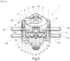
[
Fig.6 ] est une vue en coupe perspective de l'interrupteur thermique après sertissage.[Fig.6 ] is a perspective cross-sectional view of the thermal switch after crimping.
Si l'on se réfère à la [
L'interrupteur thermique 1 comprend un boîtier isolant 2 dans lequel sont montés des première 3a et seconde 3b paires de lames métalliques et un mécanisme d'ouverture/fermeture de contact 4 actionnable par la température.The
Il est à noter que l'interrupteur thermique 1 pourrait également comprendre une unique paire de lames ou au moins trois paires de lames, sans s'écarter du cadre de la présente invention.It is noted that the
Les lames des première et seconde paires de lames 3a, 3b sont disposées dans le même plan, mais pourraient également être disposées dans des plans parallèles différents, sans s'écarter du cadre de la présente invention.The blades of the first and second pairs of
Le mécanisme d'ouverture/fermeture de contact 4 est configuré pour ouvrir/fermer simultanément un contact entre les deux lames de la première paire de lames 3a et un contact entre les deux lames de la seconde paire de lames 3b en fonction de la température.The contact opening/
Le mécanisme d'ouverture/fermeture de contact 4 comprend un ensemble membrane métallique 4a relié à un capillaire thermosensible 4b de type tortillon, de manière à former un train thermostatique pour l'interrupteur thermique 1.The contact opening/
Il est à noter que le capillaire thermosensible 4b pourrait également être de type épingle ou autre, sans s'écarter du cadre de la présente invention.It should be noted that the
En outre, le capillaire thermosensible 4b et l'ensemble membrane métallique 4a pourraient également être remplacés par un disque bimétallique thermosensible, sans s'écarter du cadre de la présente invention.Furthermore, the heat-
Le boîtier isolant 2 comprend une première partie de boîtier 5 et une seconde partie de boîtier 6 entre lesquelles sont bloquées les deux paires de lames 3a, 3b.The insulating
La seconde partie de boîtier 6 est constituée d'un premier élément inférieur 6a et d'un second élément supérieur 6b entre lesquels l'ensemble membrane métallique 4a est bloqué en position, le second élément supérieur 6b épousant la partie supérieure de l'ensemble membrane métallique 4a.The
Les première et seconde parties de boîtier 5, 6 sont assemblées entre elles par sertissage des extrémités libres de quatre saillies de sertissage 7 formées sur la première partie de boîtier 5 et traversant des trous traversants 8 correspondants formés sur la seconde partie de boîtier 6, de manière à bloquer les lames 3a, 3b et le mécanisme d'ouverture/fermeture 4 à l'intérieur du boîtier isolant 2.The first and
Il est à noter que les saillies de sertissage 7 pourraient également être formées sur la seconde partie de boîtier 6 et les trous traversants 8 formés sur la première partie de boîtier 5, le sertissage étant alors réalisé en partie inférieure de l'interrupteur thermique 1, sans s'écarter du cadre de la présente invention. De même, certaines saillies de sertissage 7 pourraient être formées sur la première partie de boîtier 5 et d'autres saillies de sertissage 7 formées sur la seconde partie de boîtier 6, sans s'écarter du cadre de la présente invention.It is noted that the crimping
Les quatre saillies de sertissage 7 sont réparties autour de l'ensemble membrane métallique 4a, disposées respectivement aux quatre coins du boîtier isolant 2.The four crimping
Il est à noter que l'interrupteur thermique 1 pourrait également comporter uniquement deux saillies de sertissage 7 diamétralement opposées, sans s'écarter du cadre de la présente invention. En outre, l'interrupteur thermique 1 pourrait également comporter trois ou au moins cinq saillies de sertissage 7, sans s'écarter du cadre de la présente invention.It is noted that the
Le sertissage des extrémités libres des saillies de sertissage 7 permet ainsi de rendre inviolable l'assemblage de l'interrupteur thermique 1.Crimping the free ends of the crimping
Le boîtier isolant 2 est réalisé en au moins un matériau parmi du poly(téréphtalate de butylène) (PBT) chargé avec des fibres de verre et du polyamide 6 (PA6) chargé avec des fibres de verre. Le matériau utilisé pour le boîtier isolant 2 possède ainsi une bonne tenue au feu et est approprié pour le sertissage plastique des extrémités libres des saillies de sertissage 7.The insulating
Dans le cas où les lames 3a, 3b de l'interrupteur thermique 1 sont reliées à un circuit électrique d'un chauffe-eau électrique, l'ouverture du contact entre les deux lames d'une même paire de lames 3a, 3b lorsque le mécanisme d'ouverture/fermeture de contact 4 est actionné dès que la température dépasse un certain seuil de température permet de protéger les utilisateurs vis-à-vis d'une montée en température excessive du chauffe-eau électrique.In the case where the
Chaque paire de lames 3a, 3b peut, par exemple, être reliée à l'une des phases d'alimentation électrique du réseau électrique.Each pair of
Si l'on se réfère à la [
L'ensemble membrane métallique 4a est constitué d'une membrane métallique circulaire externe (visible sur la [
Les membranes externe et interne de l'ensemble membrane métallique 4a peuvent, par exemple, être réalisées en acier (inoxydable, ferritique ou faiblement allié).L'intérieur du capillaire 4b est en communication fluidique avec l'intérieur de l'ensemble membrane métallique 4a, un liquide étant présent entre les membranes externe et interne de l'ensemble membrane métallique 4a et dans le capillaire 4b, le passage dudit liquide en phase vapeur ou bien la dilatation dudit liquide lorsque la température dépasse un certain seuil prédéfini entraînant la déformation de l'ensemble membrane métallique 4a dans l'interrupteur thermique 1.The outer and inner membranes of the
Pour chacune des première et seconde paires de lames 3a et 3b, une lamelle métallique 9 est disposée sous les deux lames 3b de la paire, un ressort de compression 10 disposé sous la lamelle métallique 9 entraînant la mise en contact de la lamelle métallique 9 avec les deux lames 3b et établissant ainsi un contact entre les deux lames 3b de la paire, de telle sorte que le contact est normalement fermé.For each of the first and second pairs of
Le mécanisme d'ouverture/fermeture de contact 4 comprend en outre un coulisseau vertical 11 disposé entre la partie inférieure de l'ensemble membrane métallique 4a et la partie supérieure des deux lamelles métalliques 9.The contact opening/
La déformation de l'ensemble membrane métallique 4a lorsque la température dépasse le seuil de température prédéfini entraîne le déplacement vers le bas du coulisseau vertical 11 et ainsi le déplacement vers le bas des deux lamelles métalliques 9, ce qui provoque l'ouverture du contact entre les lames 3a, 3b d'une même paire.The deformation of the
Ainsi, lorsque l'ensemble membrane métallique 4a est incurvé vers le haut (température inférieure au seuil de température), le contact est fermé entre les lames 3a, 3b d'une même paire, et, lorsque l'ensemble membrane métallique 4a est incurvé vers le bas (température supérieure ou égale au seuil de température), le contact est ouvert entre les lames 3a, 3b d'une même paire, ce qui permet de protéger le circuit électrique relié aux lames 3a, 3b.Thus, when the
De préférence, un appui, par l'utilisateur, sur le coulisseau vertical 11 à l'arrière de l'interrupteur thermique 1 est nécessaire pour remettre en contact les lamelles métalliques 9 avec les lames 9a, 9b et ainsi refermer les contacts.Preferably, a press by the user on the
Si l'on se réfère aux
Pour chacune des quatre lames métalliques 3a, 3b, la première partie de boîtier 5 porte trois saillies de positionnement 12 et une saillie de sertissage 7.For each of the four
Il est à noter que les saillies de positionnement 12 pourraient également être portées par la seconde partie de boîtier 6, sans s'écarter du cadre de la présente invention.It should be noted that the
En outre, pour chaque lame 3a, 3b, le boîtier isolant 2 pourrait porter un nombre quelconque de saillies de positionnement 12, sans s'écarter du cadre de la présente invention.Furthermore, for each
Chacune des quatre lames 3a, 3b possède quatre encoches latérales 13 complémentaires des saillies de positionnement 12 et de sertissage 7 correspondantes pour l'insertion de la lame 3a, 3b sur les saillies de positionnement 12 et de sertissage 7 correspondantes, de telle sorte que chaque lame 3a, 3b est bloquée en position dans son propre plan.Each of the four
Les saillies de sertissage 7 servent ainsi également de saillies de positionnement pour les lames 3a, 3b.The crimping
Au moins l'une des encoches 13 pourrait également être une encoche centrale formée dans l'épaisseur de la lame 3a, 3b et traversée par l'une des saillies 12, 7, sans s'écarter du cadre de la présente invention.At least one of the
Il est à noter que le boîtier isolant 2 pourrait également comporter une unique saillie par lame métallique 3a, 3b, ladite unique saillie servant à la fois de saillie de positionnement et de saillie de sertissage, ladite unique saillie pouvant par exemple traverser de manière ajustée un orifice formé dans l'épaisseur de la lame 3a, 3b correspondante puis traverser le trou traversant 8 correspondant de la seconde partie de boîtier 6 pour permettre le sertissage de son extrémité libre.It should be noted that the insulating
La hauteur des saillies de sertissage 7 est supérieure à celle des saillies de positionnement 12.The height of the crimping
Chaque saillie de positionnement 12 est sous la forme d'un ergot parallélépipédique, et chaque saillie de sertissage 7 est constitué d'un ergot parallélépipédique 7a surmonté d'un cylindre 7b. Ainsi, lors du montage des lames 3a, 3b sur la première partie de boîtier 5, les encoches 13 des lames 3a, 3b sont insérées sur les ergots parallélépipédiques des saillies 7, 12 de manière à permettre le blocage des lames 3a, 3b dans leurs propres plans. Ensuite, lors de l'assemblage des première et seconde parties de boîtier 5, 6, les cylindres 7b des saillies de sertissage 7 traversent les trous traversants 8 correspondants formés dans la seconde partie de boîtier 6, puis les extrémités libres des cylindres 7b sont serties.Each
Si l'on se réfère à la [
Le premier élément inférieur 6a de la seconde partie de boîtier 6 est monté sur la première partie de boîtier 5 de telle sorte que chacune des saillies de sertissage 7 traverse un trou traversant 8a correspondant formé dans le premier élément inférieur 6a de la seconde partie de boîtier 6.The first
Quatre cylindres 17 formés sous le premier élément inférieur 6a de la seconde partie de boîtier 6 viennent, respectivement, en appui contre les quatre lames 3a, 3b.Four
Ensuite, l'ensemble membrane métallique 4a est monté sur le premier élément inférieur 6a de la seconde partie de boîtier 6, puis le second élément supérieur 6b de la seconde partie de boîtier 6 est monté sur le premier élément inférieur 6a de la seconde partie de boîtier 6 de telle sorte que chacune des saillies de sertissage 7 traverse un trou traversant 8b correspondant formé dans le second élément supérieur 6b de la seconde partie de boîtier 6, l'extrémité libre de chacune des saillies de sertissage 7 débouchant du trou traversant 8b correspondant et étant configurée pour être sertie de manière à bloquer la position des lames 3a, 3b dans la direction perpendiculaire au plan des lames 3a, 3b.Next, the
Si l'on se réfère à la [
Un sertissage plastique des extrémités libres des saillies de sertissage 7 est, de préférence, réalisé à l'aide d'un sertissage gyroscopique, mais pourrait également être réalisé à l'aide d'un rivetage radial ou d'un rivetage orbital, sans s'écarter du cadre de la présente invention.Plastic crimping of the free ends of the crimping
Ainsi, les lames métalliques 3a, 3b sont complètement bloquées en position dans le boîtier isolant 2, les saillies de positionnement 12 et les ergots parallélépipédiques 7a des saillies de sertissage 7 permettant de bloquer les lames 3a, 3b dans leurs propres plans, et le sertissage des extrémités libres des cylindres 7b des saillies de sertissage 7 permettant de brider la seconde partie de boîtier 6 sur la première partie de boîtier 5 et ainsi de bloquer les lames 3a, 3b dans la direction perpendiculaire au plan des lames 3a, 3b.Thus, the
Lors du sertissage plastique, les extrémités libres des saillies de sertissage 7 sont déformées et écrasées, ce qui permet de bloquer la seconde partie de boîtier 6 sur la première partie de boîtier 5.During plastic crimping, the free ends of the crimping
Le sertissage des extrémités libres des saillies de sertissage 7 permet ainsi de garantir l'inviolabilité de l'assemblage de l'interrupteur thermique 1.The crimping of the free ends of the crimping
Les saillies de positionnement 12 et de sertissage 7 du boîtier isolant 2 permettent ainsi le blocage des lames métalliques 3a, 3b et la fermeture du boîtier isolant 2 en une seule opération, ce qui permet d'assembler de manière fiable et définitive l'ensemble des composants de l'interrupteur thermique 1, notamment les lames métalliques 3a, 3b permettant le passage du courant et le mécanisme d'ouverture/fermeture de contact 4.The
La présente invention permet à l'interrupteur thermique 1 d'être démontable lors de la fabrication, d'améliorer la précision du produit final (température plus précise), d'augmenter la robustesse du produit lors des manipulations par l'installeur et de réduire les coûts de montage et le nombre de composants.The present invention allows the
La fermeture du boîtier isolant 2 par sertissage permet également de détecter une éventuelle effraction de l'interrupteur thermique 1 en clientèle, étant donné que le sertissage ne peut plus être remis en état une fois détruit.Closing the insulating
La partie arrière de la première partie de boîtier 5 porte en outre un pas de vis 14 sur lequel est monté un écrou 15, et un détrompeur 16 pour permettre la fixation de l'interrupteur thermique 1 sur un support.The rear part of the
Un procédé de montage de l'interrupteur thermique 1 comprend les étapes suivantes : disposer les première et seconde paires de lames 3a, 3b sur la première partie de boîtier 5 de manière à ce que les saillies de positionnement 12 bloquent la position de chaque lame 3a, 3b dans son propre plan ; disposer le mécanisme d'ouverture/fermeture de contact 4 et la seconde partie de boîtier 6 sur la première partie de boîtier 5 de manière à ce que chacune des saillies de sertissage 7 traverse le trou traversant 8 correspondant ; et réaliser un sertissage sur l'extrémité libre de chacune des saillies de sertissage 7 débouchant du trou traversant 8 correspondant de manière à bloquer la position des lames 3a, 3b dans la direction perpendiculaire au plan des lames 3a, 3b.A method of mounting the
Claims (12)
- - A thermal switch (1) comprising an insulating housing (2) in which are mounted at least one pair of metal blades (3a, 3b) and a temperature operated contact opening/closing mechanism (4) between the blades (3a, 3b) of the at least one pair of blades (3a, 3b), the insulating housing (2) comprising a first housing part (5) and a second housing part (6), characterised in that at least one of the first and second housing parts (5, 6) has, for each blade (3a, 3b) of the at least one pair of blades (3a, 3b), at least one positioning projection (12) which locks the position of said blade (3a, 3b) in its own plane, at least two crimping projections (7) being formed on at least one of the first and second housing parts (5, 6), the second housing part (6) being mounted on the first housing part (5) such that each of the at least two crimping projections (7) passes through a corresponding through hole (8) formed in the other of the first and second housing parts (5, 6), the free end of each of the at least two crimping projections (7) emerging from the corresponding through hole (8) and being configured to be crimped so as to lock the position of the blades (3a, 3b) in the direction perpendicular to the planes of the blades (3a, 3b).
- - A thermal switch (1) according to claim 1, characterised in that the height of the at least two crimping projections (7) is greater than that of the positioning projections (12).
- - A thermal switch (1) according to claim 1 or 2, characterised in that the at least two crimping projections (7) are also positioning projections.
- - A thermal switch (1) according to claim 3, characterised in that each blade (3a, 3b) of the at least one pair of blades (3a, 3b) is locked by three positioning projections (12) and a crimping projection (7).
- - A thermal switch (1) according to one of claims 1 to 4, characterised in that notches (13) are formed on each blade (3a, 3b) of the at least one pair of blades (3a, 3b), said notches (13) being complementary to the positioning projections (12) for inserting the blades (3a, 3b) of the at least one pair of blades (3a, 3b) on the positioning projections (12).
- - A thermal switch (1) according to one of claims 1 to 5, characterised in that each positioning projection (12) is a parallelepipedal lug, and each crimping projection (7) is one of a cylinder (7b) and a parallelepipedal lug (7a) surmounted by a cylinder (7b).
- - A thermal switch (1) according to one of claims 1 to 6, characterised in that it comprises two pairs of blades (3a, 3b) having the same contact opening/closing mechanism (4) .
- - A thermal switch (1) according to one of claims 1 to 7, characterised in that the contact opening/closing mechanism (4) comprises a thermosensitive element deformable by temperature.
- - A thermal switch (1) according to claim 8, characterised in that the second housing part (6) consists of two elements (6a, 6b) between which the thermosensitive element is locked.
- - A thermal switch (1) according to claim 8 or 9, characterised in that the thermosensitive element is one of a bimetallic disc and a thermosensitive capillary (4b) connected to a metal membrane assembly (4a).
- - A thermal switch (1) according to one of claims 1 to 10, characterised in that the insulating housing (2) is made of at least one material from polybutylene terephthalate, PBT, filled with glass fibres and polyamide 6, PA6, filled with glass fibres.
- - A method of mounting a thermal switch (1) according to one of claims 1 to 11, characterised in that it comprises the following steps:arranging the at least one pair of blades (3a, 3b) on the first housing part (5) so that the positioning projections (12) lock the position of each blade (3a, 3b) of the at least one pair of blades (3a, 3b) in its own plane;arranging the contact opening/closing mechanism (4) and the second housing part (6) on the first housing part (5) so that each of the at least two crimping projections (7) passes through the corresponding through hole (8); andcrimping the free end of each of the at least two crimping projections (7) emerging from the corresponding through hole (8) so as to lock the position of the blades (3a, 3b) in the direction perpendicular to the planes of the blades (3a, 3b).
Priority Applications (1)
| Application Number | Priority Date | Filing Date | Title |
|---|---|---|---|
| RS20250214A RS66571B1 (en) | 2020-11-17 | 2021-10-18 | Thermal switch with tamper-proof assembly and its mounting method |
Applications Claiming Priority (2)
| Application Number | Priority Date | Filing Date | Title |
|---|---|---|---|
| FR2011767A FR3116376B1 (en) | 2020-11-17 | 2020-11-17 | THERMAL SWITCH WITH TAMPER-PROOF ASSEMBLY AND ITS ASSEMBLY METHOD |
| PCT/IB2021/059555 WO2022106931A1 (en) | 2020-11-17 | 2021-10-18 | Thermal switch having tamper-proof assembly, and method for mounting same |
Publications (3)
| Publication Number | Publication Date |
|---|---|
| EP4248472A1 EP4248472A1 (en) | 2023-09-27 |
| EP4248472B1 true EP4248472B1 (en) | 2024-12-04 |
| EP4248472C0 EP4248472C0 (en) | 2024-12-04 |
Family
ID=74758929
Family Applications (1)
| Application Number | Title | Priority Date | Filing Date |
|---|---|---|---|
| EP21805615.8A Active EP4248472B1 (en) | 2020-11-17 | 2021-10-18 | Thermal switch with tamper-proof assembly and its mounting method |
Country Status (6)
| Country | Link |
|---|---|
| EP (1) | EP4248472B1 (en) |
| ES (1) | ES3004945T3 (en) |
| FR (1) | FR3116376B1 (en) |
| PL (1) | PL4248472T3 (en) |
| RS (1) | RS66571B1 (en) |
| WO (1) | WO2022106931A1 (en) |
Family Cites Families (3)
| Publication number | Priority date | Publication date | Assignee | Title |
|---|---|---|---|---|
| DE102005060965B4 (en) * | 2005-06-28 | 2007-08-16 | Inter Control Hermann Köhler Elektrik GmbH & Co. KG | Thermal fuse with process for its preparation |
| TW201735474A (en) * | 2016-03-07 | 2017-10-01 | Otsuka Techno Corp | USB plug |
| CN110867341A (en) * | 2019-11-07 | 2020-03-06 | 太平洋电子(昆山)有限公司 | A contact bimetal thermostat |
-
2020
- 2020-11-17 FR FR2011767A patent/FR3116376B1/en active Active
-
2021
- 2021-10-18 PL PL21805615.8T patent/PL4248472T3/en unknown
- 2021-10-18 EP EP21805615.8A patent/EP4248472B1/en active Active
- 2021-10-18 ES ES21805615T patent/ES3004945T3/en active Active
- 2021-10-18 WO PCT/IB2021/059555 patent/WO2022106931A1/en not_active Ceased
- 2021-10-18 RS RS20250214A patent/RS66571B1/en unknown
Also Published As
| Publication number | Publication date |
|---|---|
| ES3004945T3 (en) | 2025-03-13 |
| FR3116376B1 (en) | 2022-10-07 |
| EP4248472A1 (en) | 2023-09-27 |
| FR3116376A1 (en) | 2022-05-20 |
| PL4248472T3 (en) | 2025-04-07 |
| RS66571B1 (en) | 2025-03-31 |
| EP4248472C0 (en) | 2024-12-04 |
| WO2022106931A1 (en) | 2022-05-27 |
Similar Documents
| Publication | Publication Date | Title |
|---|---|---|
| EP0366519B1 (en) | Security device for a switching apparatus made by the assembly of several removable modular elements | |
| EP0174246B1 (en) | Locking device for the operation of an electrical apparatus with manual operation | |
| EP0309311A1 (en) | Overcurrent circuit-breaker | |
| FR2523796A1 (en) | DEVICE FOR PROTECTING ELECTRICAL IMMERSE HEATING ELEMENTS | |
| EP4248472B1 (en) | Thermal switch with tamper-proof assembly and its mounting method | |
| EP4248476B1 (en) | Thermal switch with tamper-proof heat-sensitive element attachment and method of mounting same | |
| EP2897154B1 (en) | Surge arrester and self-protected electrical assembly comprising such a surge arrester and a circuit breaker | |
| EP0758961B1 (en) | Lighter body for a cigarette lighter, particularly in motor vehicles | |
| EP4186084B1 (en) | Arc extinguishing chamber for electrical protection apparatus and electrical protection apparatus comprising at least one such arc extinguishing chamber | |
| EP0699556B1 (en) | Cigarette lighter body, especially for motor vehicles | |
| EP3651173B1 (en) | Switching assembly with secure attaching solution for emergency stop device | |
| WO2017037371A1 (en) | Electric household appliance comprising a hot plate supplied with power by a thermostat fitted with a thermal cut-out | |
| EP3161850B1 (en) | Thermal-magnetic tripping mechanism | |
| EP2200065B1 (en) | Electromagnetic release device for line protection switch with at least two protected poles | |
| EP1288978B1 (en) | Electrical security apparatus provided with lockable reset and signaling lever | |
| FR2639146A1 (en) | Switching apparatus of the type comprising a main switching module and a removable auxiliary contact module | |
| EP3644339B1 (en) | Apparatus for interrupting an electric current | |
| EP1708221B1 (en) | Protection device comprising a fuse and an insulation element for switching off, and use of said device in a lightning arrestor | |
| EP2227818A2 (en) | Thermal safety device | |
| EP1501112B1 (en) | Improved magnetic sub-unit and circuit breaker comprising this sub-unit | |
| EP1708222B1 (en) | Protection device having a crimped element biased in the switching off direction, and use of said device in a lightning arrestor | |
| EP2743956B1 (en) | Electric current breaking apparatus, in particular a coupling breaker | |
| EP3629351A1 (en) | Actuating system for electrical switching appliance | |
| EP2575151A1 (en) | Reinforcement of the sectioning mechanism of a multi-modular electrical appliance such as a circuit breaker | |
| FR2589293A1 (en) | PROTECTION DEVICE FOR AN ELECTRIC MOTOR, PARTICULARLY FOR THE COMPRESSOR MOTOR OF A REFRIGERATION MACHINE |
Legal Events
| Date | Code | Title | Description |
|---|---|---|---|
| STAA | Information on the status of an ep patent application or granted ep patent |
Free format text: STATUS: UNKNOWN |
|
| STAA | Information on the status of an ep patent application or granted ep patent |
Free format text: STATUS: THE INTERNATIONAL PUBLICATION HAS BEEN MADE |
|
| PUAI | Public reference made under article 153(3) epc to a published international application that has entered the european phase |
Free format text: ORIGINAL CODE: 0009012 |
|
| STAA | Information on the status of an ep patent application or granted ep patent |
Free format text: STATUS: REQUEST FOR EXAMINATION WAS MADE |
|
| 17P | Request for examination filed |
Effective date: 20230330 |
|
| AK | Designated contracting states |
Kind code of ref document: A1 Designated state(s): AL AT BE BG CH CY CZ DE DK EE ES FI FR GB GR HR HU IE IS IT LI LT LU LV MC MK MT NL NO PL PT RO RS SE SI SK SM TR |
|
| DAV | Request for validation of the european patent (deleted) | ||
| DAX | Request for extension of the european patent (deleted) | ||
| GRAP | Despatch of communication of intention to grant a patent |
Free format text: ORIGINAL CODE: EPIDOSNIGR1 |
|
| STAA | Information on the status of an ep patent application or granted ep patent |
Free format text: STATUS: GRANT OF PATENT IS INTENDED |
|
| INTG | Intention to grant announced |
Effective date: 20240617 |
|
| GRAS | Grant fee paid |
Free format text: ORIGINAL CODE: EPIDOSNIGR3 |
|
| GRAA | (expected) grant |
Free format text: ORIGINAL CODE: 0009210 |
|
| STAA | Information on the status of an ep patent application or granted ep patent |
Free format text: STATUS: THE PATENT HAS BEEN GRANTED |
|
| AK | Designated contracting states |
Kind code of ref document: B1 Designated state(s): AL AT BE BG CH CY CZ DE DK EE ES FI FR GB GR HR HU IE IS IT LI LT LU LV MC MK MT NL NO PL PT RO RS SE SI SK SM TR |
|
| REG | Reference to a national code |
Ref country code: CH Ref legal event code: EP |
|
| REG | Reference to a national code |
Ref country code: DE Ref legal event code: R096 Ref document number: 602021023003 Country of ref document: DE |
|
| REG | Reference to a national code |
Ref country code: IE Ref legal event code: FG4D Free format text: LANGUAGE OF EP DOCUMENT: FRENCH |
|
| U01 | Request for unitary effect filed |
Effective date: 20250103 |
|
| REG | Reference to a national code |
Ref country code: ES Ref legal event code: FG2A Ref document number: 3004945 Country of ref document: ES Kind code of ref document: T3 Effective date: 20250313 |
|
| U07 | Unitary effect registered |
Designated state(s): AT BE BG DE DK EE FI FR IT LT LU LV MT NL PT RO SE SI Effective date: 20250217 |
|
| PG25 | Lapsed in a contracting state [announced via postgrant information from national office to epo] |
Ref country code: HR Free format text: LAPSE BECAUSE OF FAILURE TO SUBMIT A TRANSLATION OF THE DESCRIPTION OR TO PAY THE FEE WITHIN THE PRESCRIBED TIME-LIMIT Effective date: 20241204 |
|
| PG25 | Lapsed in a contracting state [announced via postgrant information from national office to epo] |
Ref country code: NO Free format text: LAPSE BECAUSE OF FAILURE TO SUBMIT A TRANSLATION OF THE DESCRIPTION OR TO PAY THE FEE WITHIN THE PRESCRIBED TIME-LIMIT Effective date: 20250304 |
|
| PG25 | Lapsed in a contracting state [announced via postgrant information from national office to epo] |
Ref country code: GR Free format text: LAPSE BECAUSE OF FAILURE TO SUBMIT A TRANSLATION OF THE DESCRIPTION OR TO PAY THE FEE WITHIN THE PRESCRIBED TIME-LIMIT Effective date: 20250305 |
|
| PG25 | Lapsed in a contracting state [announced via postgrant information from national office to epo] |
Ref country code: SM Free format text: LAPSE BECAUSE OF FAILURE TO SUBMIT A TRANSLATION OF THE DESCRIPTION OR TO PAY THE FEE WITHIN THE PRESCRIBED TIME-LIMIT Effective date: 20241204 |
|
| PG25 | Lapsed in a contracting state [announced via postgrant information from national office to epo] |
Ref country code: IS Free format text: LAPSE BECAUSE OF FAILURE TO SUBMIT A TRANSLATION OF THE DESCRIPTION OR TO PAY THE FEE WITHIN THE PRESCRIBED TIME-LIMIT Effective date: 20250404 |
|
| PG25 | Lapsed in a contracting state [announced via postgrant information from national office to epo] |
Ref country code: SK Free format text: LAPSE BECAUSE OF FAILURE TO SUBMIT A TRANSLATION OF THE DESCRIPTION OR TO PAY THE FEE WITHIN THE PRESCRIBED TIME-LIMIT Effective date: 20241204 |
|
| PLBE | No opposition filed within time limit |
Free format text: ORIGINAL CODE: 0009261 |
|
| STAA | Information on the status of an ep patent application or granted ep patent |
Free format text: STATUS: NO OPPOSITION FILED WITHIN TIME LIMIT |
|
| 26N | No opposition filed |
Effective date: 20250905 |
|
| U20 | Renewal fee for the european patent with unitary effect paid |
Year of fee payment: 5 Effective date: 20251030 |
|
| PGFP | Annual fee paid to national office [announced via postgrant information from national office to epo] |
Ref country code: GB Payment date: 20251014 Year of fee payment: 5 |
|
| PGFP | Annual fee paid to national office [announced via postgrant information from national office to epo] |
Ref country code: TR Payment date: 20251013 Year of fee payment: 5 |
|
| PGFP | Annual fee paid to national office [announced via postgrant information from national office to epo] |
Ref country code: CZ Payment date: 20251008 Year of fee payment: 5 |
|
| PGFP | Annual fee paid to national office [announced via postgrant information from national office to epo] |
Ref country code: PL Payment date: 20251006 Year of fee payment: 5 |
|
| PGFP | Annual fee paid to national office [announced via postgrant information from national office to epo] |
Ref country code: RS Payment date: 20251007 Year of fee payment: 5 |
|
| PGFP | Annual fee paid to national office [announced via postgrant information from national office to epo] |
Ref country code: ES Payment date: 20251107 Year of fee payment: 5 |