EP4248476B1 - Thermischer schalter mit manipulationssicherer befestigung eines thermosensitiven elements und verfahren zu seiner montage - Google Patents
Thermischer schalter mit manipulationssicherer befestigung eines thermosensitiven elements und verfahren zu seiner montage Download PDFInfo
- Publication number
- EP4248476B1 EP4248476B1 EP21805617.4A EP21805617A EP4248476B1 EP 4248476 B1 EP4248476 B1 EP 4248476B1 EP 21805617 A EP21805617 A EP 21805617A EP 4248476 B1 EP4248476 B1 EP 4248476B1
- Authority
- EP
- European Patent Office
- Prior art keywords
- flange
- housing part
- thermal switch
- thermosensitive element
- projections
- Prior art date
- Legal status (The legal status is an assumption and is not a legal conclusion. Google has not performed a legal analysis and makes no representation as to the accuracy of the status listed.)
- Active
Links
Images


Classifications
-
- H—ELECTRICITY
- H01—ELECTRIC ELEMENTS
- H01H—ELECTRIC SWITCHES; RELAYS; SELECTORS; EMERGENCY PROTECTIVE DEVICES
- H01H37/00—Thermally-actuated switches
- H01H37/02—Details
- H01H37/04—Bases; Housings; Mountings
-
- H—ELECTRICITY
- H01—ELECTRIC ELEMENTS
- H01H—ELECTRIC SWITCHES; RELAYS; SELECTORS; EMERGENCY PROTECTIVE DEVICES
- H01H1/00—Contacts
- H01H1/58—Electric connections to or between contacts; Terminals
-
- H—ELECTRICITY
- H01—ELECTRIC ELEMENTS
- H01H—ELECTRIC SWITCHES; RELAYS; SELECTORS; EMERGENCY PROTECTIVE DEVICES
- H01H1/00—Contacts
- H01H1/12—Contacts characterised by the manner in which co-operating contacts engage
- H01H1/14—Contacts characterised by the manner in which co-operating contacts engage by abutting
- H01H1/20—Bridging contacts
- H01H1/2025—Bridging contacts comprising two-parallel bridges
- H01H2001/2033—Bridging contacts comprising two-parallel bridges with a contact bridge on both opposite sides of a fixed contact pair, each contact bridge being moved to close or open the circuit
-
- H—ELECTRICITY
- H01—ELECTRIC ELEMENTS
- H01H—ELECTRIC SWITCHES; RELAYS; SELECTORS; EMERGENCY PROTECTIVE DEVICES
- H01H37/00—Thermally-actuated switches
- H01H37/02—Details
- H01H37/32—Thermally-sensitive members
- H01H37/52—Thermally-sensitive members actuated due to deflection of bimetallic element
- H01H37/54—Thermally-sensitive members actuated due to deflection of bimetallic element wherein the bimetallic element is inherently snap acting
- H01H2037/549—Details of movement transmission between bimetallic snap element and contact
-
- H—ELECTRICITY
- H01—ELECTRIC ELEMENTS
- H01H—ELECTRIC SWITCHES; RELAYS; SELECTORS; EMERGENCY PROTECTIVE DEVICES
- H01H37/00—Thermally-actuated switches
- H01H37/02—Details
- H01H37/32—Thermally-sensitive members
- H01H37/34—Means for transmitting heat thereto, e.g. capsule remote from contact member
-
- H—ELECTRICITY
- H01—ELECTRIC ELEMENTS
- H01H—ELECTRIC SWITCHES; RELAYS; SELECTORS; EMERGENCY PROTECTIVE DEVICES
- H01H37/00—Thermally-actuated switches
- H01H37/02—Details
- H01H37/64—Contacts
Definitions
- the present invention relates to the field of thermal switches, and in particular relates to a thermal switch with tamper-proof thermosensitive element fixing and to its mounting method.
- Thermal switches also called temperature-actuated switches, electromechanical microswitches, or thermal circuit breakers
- bimetallic switches are safety devices that mechanically trigger a contact, which opens a protected electrical circuit, when the thermal switch heats up.
- Thermal switches generally consist of an insulating housing in which are mounted at least one pair of metal blades connected to a protected electrical circuit, a temperature-deformable heat-sensitive element (such as a heat-sensitive bimetallic disk or circular metal membranes connected to a heat-sensitive capillary) and a contact opening/closing mechanism between the blades of the at least one pair of blades which is configured to be actuated by the heat-sensitive element.
- the protected electrical circuit may, for example, be part of a water heater or any other device such as an electric heating device for private or collective use.
- thermosensitive element in the insulating housing of the thermal switch
- this solution involves the use of additional components and requires the addition of a component to guarantee tamper-proofness
- crimping the thermosensitive element on the insulating housing of the thermal switch however this solution can cause a temperature shift of the thermosensitive element, leads to a moderately robust fixing (possible sliding of the thermosensitive element on the insulating housing of the thermal switch), and allows the thermosensitive element to be forced back into place without any apparent sign following disassembly by the customer.
- the present invention aims to solve the drawbacks of the prior state of the technique by proposing a thermal switch comprising an insulating housing in which are mounted at least one pair of metal blades, a circular heat-sensitive element deformable by temperature and a contact opening/closing mechanism between the blades of the at least one pair of blades which is configured to be actuated by the heat-sensitive element, the heat-sensitive element being radially blocked in the insulating housing by means of a heat-sensitive element support and being axially blocked in the insulating housing by means of a flange and at least two projections whose free ends are configured to be crimped in order to obtain a tamper-proof fixing of the heat-sensitive element in the insulating housing and to allow a reduction in costs, given that no additional components are necessary to guarantee the tamper-proofness of the thermal switch according to the present invention.
- the present invention therefore relates to a thermal switch comprising an insulating housing in which are mounted at least one pair of metal blades, a circular heat-sensitive element deformable by temperature and a mechanism for opening/closing contact between the blades of the at least one pair of blades which is configured to be actuated by the heat-sensitive element, characterized in that the insulating housing comprises a first housing part in which the at least one pair of blades is blocked, the upper face of the first housing part comprising in the central part a heat-sensitive element support, the heat-sensitive element having a base which is complementary to the heat-sensitive element support and is arranged thereon so as to radially block the position of the heat-sensitive element, the insulating housing further comprising a flange having a central opening complementary to the cross-section of the upper part of the heat-sensitive element, at least two projections being carried in the peripheral part by at least one of the upper face of the first housing part and the lower face of the flange, the flange being mounted on the first housing part in
- the opening of a contact between the two blades of the same pair of blades by the contact opening/closing mechanism when the heat-sensitive element is deformed during an excessive temperature makes it possible to protect users from from an excessive temperature rise of the electric water heater.
- the arrangement of the base of the heat-sensitive element on the heat-sensitive element support of the insulating housing makes it possible to radially lock the position of the heat-sensitive element in the insulating housing, and the arrangement of the flange on the base and the crimping of the at least two projections make it possible to axially lock the position of the base of the heat-sensitive element in the insulating housing, which makes it possible to reliably and permanently fix the heat-sensitive element in the insulating housing of the thermal switch.
- metal blades can be arranged in the same plane or in different parallel planes.
- Crimping the free ends of the at least two projections ensures the tamper-proof nature of the thermal switch assembly.
- the crimping of the at least two projections of the insulating housing allows the blocking of the base of the heat-sensitive element and the closing of the insulating housing in a single operation, which makes it possible to reliably and definitively assemble all the components of the thermal switch, in particular the metal blades allowing the passage of current, the contact opening/closing mechanism and the heat-sensitive element deformable by temperature.
- the present invention thus consists in clamping the heat-sensitive element between two parts (namely, the first housing part and the clamp) and in deforming the at least two projections by crimping so that the two clamping parts can no longer move and thus fix the heat-sensitive element.
- the present invention thus makes it possible to reduce the number of operations and components during assembly, to avoid scrap (the thermal switch being removable and repairable up to the last crimping operation), to guarantee the plating of the thermosensitive element in position without drift during use, to allow the thermosensitive element to be maintained without damaging it (for example, its temperature shift) and to be able to detect any disassembly of the thermal switch by customers.
- the present invention makes it possible to improve the precision of the final product (more precise triggering temperature), to reduce assembly costs and the number of components, and to increase the robustness of the product during handling by the installer.
- the insulating housing has two projections, these are preferably diametrically opposed so as to guarantee the tamper-proofness of the thermal switch.
- the present invention has the following advantages: fewer parts (e.g., four fewer metal rivets); more advantageous in terms of logistics, assembly and production costs due to the reduced number of parts; furthermore allows a thermal switch tamper detection, as the crimp cannot be repaired once destroyed.
- the heat-sensitive element is one of a bimetallic disk and a circular metal membrane assembly configured to be connected to a heat-sensitive capillary.
- the circular metal membrane assembly is preferably comprised of an outer circular metal membrane and an inner circular metal membrane, a liquid being present between the outer and inner membranes, the passage of said liquid into vapor phase or the expansion of said liquid when the temperature exceeds a certain threshold causing the deformation of the outer and inner membranes, which causes the opening of the contact between the two blades of each pair of blades via the contact opening/closing mechanism.
- the external and internal membranes of the metal membrane assembly can, for example, be made of steel (stainless, ferritic or low alloy).
- the heat-sensitive capillary connected to the metal membrane assembly may, for example, be of the twist or hairpin type (for example, made of copper), the interior of the capillary being in fluid communication with the interior of the metal membrane assembly, the metal membrane assembly and the capillary thus forming a thermostatic train.
- four projections are carried in the peripheral part by at least one of the upper face of the first housing part and the lower face of the flange.
- the four projections are preferably distributed around the heat-sensitive element so as to obtain better fixing of the flange on the first housing part.
- the projections are cylindrical.
- the cylindrical projections pass through the corresponding through holes formed in the insulating housing, and then the free ends of the cylinders are crimped.
- the thermal switch comprises two pairs of blades having the same contact opening/closing mechanism.
- the same contact opening/closing mechanism allows the contact between the two blades of the first pair of blades and the contact between the two blades of the second pair of blades to be opened simultaneously when the temperature becomes excessive.
- Each pair of blades can, for example, be connected to one of the power supply phases of the electrical network.
- the first housing part is consisting of a lower element and an upper element between which at least one pair of blades is blocked.
- the metal blades are locked in position between the two elements of the first housing part when crimping the free ends of the at least two projections.
- the at least two projections extend from the lower element of the first housing part and pass through at least two corresponding through holes formed in the upper element of the first housing part, the heat-sensitive element support being formed on the upper element of the first housing part.
- crimping the free ends of the at least two projections makes it possible both to block the position of the heat-sensitive element and to block the position of the metal blades which find themselves blocked between the lower element and the upper element of the first housing part.
- the insulating housing is made of at least one material from among poly(butylene terephthalate), PBT, loaded with glass fibers and polyamide 6, PA6, loaded with glass fibers.
- the material used for the insulating housing has good fire resistance and is suitable for plastic crimping of the free ends of the at least two projections.
- the present invention also relates to a method for mounting a thermal switch as described above, characterized in that it comprises the following steps: arranging the base of the heat-sensitive element on the heat-sensitive element support of the first housing part so as to radially block the position of the heat-sensitive element; arranging the flange on the first housing part so that the upper part of the heat-sensitive element passes through the central opening of the flange, the flange rests on the base of the heat-sensitive element and each of the at least two projections carried by at least one of the first housing part and the flange passes through the corresponding through hole formed in the other of the first housing part and the flange; and performing a crimping on the free end of each of the at least two projections emerging from the corresponding through hole so as to axially block the position of the heat-sensitive element.
- the plastic crimping of the free ends of the at least two projections is preferably carried out using gyroscopic crimping, but could also be carried out using radial riveting or orbital riveting, without departing from the scope of the present invention.
- crimping could also be done ultrasonically. However, this technique is less preferred, as it poses temperature problems. (temperature too high therefore approximate crimping due to elastic return of the material).
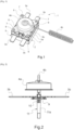
- thermal switch 1 according to the present invention is shown there.
- the thermal switch 1 comprises an insulating housing 2 in which are mounted first 3a and second 3b pairs of metal blades, a contact opening/closing mechanism (not visible in the [ Fig.1 ]) and a circular thermosensitive element deformable by temperature 4a.
- thermal switch 1 could also comprise a single pair of blades or at least three pairs of blades, without departing from the scope of the present invention.
- the blades of the first and second pairs of blades 3a, 3b are arranged in the same plane, but could also be arranged in different parallel planes, without departing from the scope of the present invention.
- thermosensitive element 4a is a metal membrane assembly connected to a tortillon-type thermosensitive capillary 4b, so as to form a thermostatic train for the thermal switch 1.
- thermosensitive capillary 4b could also be of the pin type or other, without departing from the scope of the present invention.
- heat-sensitive capillary 4b and the metal membrane assembly type heat-sensitive element 4a could also be replaced by a heat-sensitive bimetallic disk, without departing from the scope of the present invention.
- the insulating housing 2 comprises a first housing part 5 and a flange 6 between which the heat-sensitive element 4a is blocked.
- the first housing part 5 consists of a lower element 5a and an upper element 5b between which the two pairs of metal blades 3a, 3b are blocked.
- the first housing part 5 and the flange 6 are assembled together by crimping the free ends of four projections 7 formed on the first housing part 5 and passing through corresponding through holes 8 formed at the four corners of the flange 6, so as to block the heat-sensitive element 4a inside the insulating housing 2.
- projections 7 could also be formed on the flange 6 and the through holes 8 formed on the first housing part 5, the crimping then being carried out at the lower part of the thermal switch 1, without departing from the scope of the present invention.
- some projections 7 could be formed on the first housing part 5 and other projections 7 formed on the flange 6, without departing from the scope of the present invention.
- the four projections 7 are distributed around the heat-sensitive element 4a, arranged respectively at the four corners of the insulating housing 2.
- thermal switch 1 could also comprise only two diametrically opposed projections 7, without departing from the scope of the present invention. Furthermore, the thermal switch 1 could also comprise three or at least five projections 7, without departing from the scope of the present invention.
- the crimping of the free ends of the projections 7 thus makes it possible to make the assembly of the thermal switch 1 tamper-proof.
- the insulating housing 2 is made of at least one material from among polybutylene terephthalate (PBT) filled with glass fibers and polyamide 6 (PA6) filled with glass fibers.
- PBT polybutylene terephthalate
- PA6 polyamide 6
- the opening of the contact between the two blades of the same pair of blades 3a, 3b when the thermosensitive element of the metal membrane assembly type 4a is deformed as soon as the temperature exceeds a certain temperature threshold makes it possible to protect users against an excessive rise in temperature of the electric water heater.
- Each pair of blades 3a, 3b can, for example, be connected to one of the power supply phases of the electrical network.
- thermosensitive element 4a of the metal membrane assembly type there is represented the temperature-deformable thermosensitive element 4a of the metal membrane assembly type and the contact opening/closing mechanism 11 of the thermal switch 1 at the level of the second pair of blades 3b.
- the contact opening/closing mechanism 11 is configured to simultaneously open/close a contact between the two blades of the first pair of blades 3a and a contact between the two blades of the second pair of blades 3b, said mechanism 11 being controlled by the heat-sensitive element 4a as a function of the temperature.
- the temperature-deformable thermosensitive element 4a of the metal membrane assembly type consists of an external circular metal membrane (visible in the [ Fig.2 ]) and an internal circular metal membrane (not visible on the [ Fig.2 ]).
- the external and internal membranes of the thermosensitive element 4a of the metal membrane assembly type can, for example, be made of steel (stainless, ferritic or low alloy).
- the interior of the capillary 4b is in fluid communication with the interior of the thermosensitive element 4a of the metal membrane assembly type, a liquid being present between the external and internal membranes of the thermosensitive element 4a of the metal membrane assembly type and in the capillary 4b, the passage of said liquid into the vapor phase or the expansion of said liquid when the temperature exceeds a certain predefined threshold causing the deformation of the thermosensitive element 4a of the metal membrane assembly type in the thermal switch 1.
- the contact opening/closing mechanism 11 comprises a metal blade 9 disposed under the two blades 3b of the pair, and a compression spring 10 disposed under the metal blade 9 causing the metal blade 9 to come into contact with the two blades 3b of the pair and thereby establish contact between the two blades 3b of the pair, such that the contact is normally closed.
- the contact opening/closing mechanism 11 further comprises a vertical slide 11a arranged between the lower part of the heat-sensitive element 4a and the upper part of the two metal strips 9.
- thermosensitive element 4a of the metal membrane assembly type when the temperature exceeds the predefined temperature threshold causes the vertical slide 11a to move downwards and thus the two metal strips 9 to move downwards, which causes the contact between the strips 3a, 3b of the same pair to open.
- thermosensitive element 4a of the metal membrane assembly type when the thermosensitive element 4a of the metal membrane assembly type is curved upwards (temperature lower than the temperature threshold), the contact is closed between the blades 3a, 3b of the same pair, and, when the thermosensitive element 4a of the metal membrane assembly type is curved downwards (temperature greater than or equal to the temperature threshold), the contact is open between the blades 3a, 3b of the same pair, which makes it possible to protect the electrical circuit connected to the blades 3a, 3b.
- a press by the user on the vertical slide 11a at the rear of the thermal switch 1 is necessary to put the metal strips 9 back into contact with the blades 9a, 9b and thus close the contacts.
- the first housing part 5 of the thermal switch 1 is represented therein, in which the first and second pairs of metal blades 3a, 3b are arranged.
- the four projections 7 are cylindrical, extend from the lower element 5a of the first housing part 5 and pass through corresponding through holes 12 formed in the upper element 5b of the first housing part 5, the crimping of the free ends of the projections 7 after arrangement of the heat-sensitive element 4a and the flange 6 thus making it possible to block the position of the metal blades 3a, 3b which find themselves blocked between the lower element 5a and the upper element 5b of the first housing part 5.
- projections 7 could also extend directly from the upper element 5b of the first housing part 5, without departing from the scope of the present invention.
- a through hole 13 is formed in the center of the upper member 5b of the first housing part 5, to allow the passage of the upper part of the vertical slide 11a of the contact opening/closing mechanism 11.
- Two other through holes 14 are further formed on either side of the through hole 13, said two other through holes 14 allowing the passage and fixing of two clips 15 extending from the lower element 5a of the first housing part 5, so as to allow the blocking of the upper element 5b on the lower element 5a of the first housing part 5.
- the upper face of the upper element 5b of the first housing part 5 comprises, in the central part, around the through holes 13 and 14, a heat-sensitive element support 16 consisting of a ring 16a on the external face of which several protuberances 16b are formed in a distributed manner, a relief with a flat upper surface 16c being formed under each protuberance 16b.
- the rear part of the lower element 5a of the first housing part 5 further carries a screw thread 17 to allow the thermal switch 1 to be fixed to a support.
- thermosensitive element 4a of the metal membrane assembly type has a circular base 18 which is complementary to the thermosensitive element support 16, said base 18 being arranged on the heat-sensitive element support 16 so as to radially block the position of the heat-sensitive element 4a.
- the base 18 rests on the reliefs 16c of the heat-sensitive element support 16 and is fitted onto the protuberances 16b of the heat-sensitive element support 16, which allows the radial locking of the heat-sensitive element 4a on the heat-sensitive element support 16.
- thermal switch 1 is represented there before crimping.
- the flange 6 has a circular central opening 19 complementary to the cross section of the upper part of the heat-sensitive element 4a.
- the flange 6 is mounted on the upper element 5b of the first housing part 5 such that the upper part of the heat-sensitive element 4a passes through the central opening 19 of the flange 6.
- each of the four projections 7 passes through the corresponding through hole 8 formed in the flange 6, the free end of each of the four projections 7 emerging from the corresponding through hole 8 and being configured to be crimped so as to axially block the position of the base 18 of the heat-sensitive element 4a.
- thermal switch 1 is shown after crimping.
- Plastic crimping of the free ends of the projections 7 is preferably carried out using gyroscopic crimping, but could also be carried out using radial riveting or orbital riveting, without departing from the scope of the present invention.
- the arrangement of the base 18 of the heat-sensitive element 4a on the heat-sensitive element support 16 of the insulating housing 2 makes it possible to radially lock the position of the heat-sensitive element 4a in the insulating housing 2, and the arrangement of the flange 6 on the base 18 and the crimping of the projections 7 make it possible to axially lock the position of the base 18 of the heat-sensitive element 4a in the insulating housing 2, which makes it possible to reliably and definitively fix the heat-sensitive element 4a in the insulating housing 2 of the thermal switch 1.
- the crimping of the free ends of the projections 7 thus allows the blocking of the base 18 of the heat-sensitive element 4a and the closing of the insulating housing 2 in a single operation, which allows the assembly in a reliable and definitive manner of all the components of the thermal switch 1, in particular the metal blades 3a, 3b. allowing the passage of current, the contact opening/closing mechanism 11 and the temperature-deformable heat-sensitive element 4a.
- the present invention thus makes it possible to reduce the number of operations and components during assembly, to avoid scrap (the thermal switch 1 being removable and repairable up to the last crimping operation), to guarantee the plating of the thermosensitive element 4a in position without drift during use, to allow the thermosensitive element 4a to be maintained without damaging it (for example, its temperature shift) and to be able to detect any disassembly of the thermal switch 1 by customers.
- a method of mounting the thermal switch 1 comprises the following steps: arranging the base 18 of the heat-sensitive element 4a on the heat-sensitive element support 16 of the first housing part 5 so as to radially lock the position of the heat-sensitive element 4a; arranging the flange 6 on the first housing part 5 so that the upper part of the heat-sensitive element 4a passes through the central opening 19 of the flange 6, the flange 6 rests on the base 18 of the heat-sensitive element 4a and each of the projections 7 passes through the corresponding through hole 8 formed in the flange 6; and performing a crimping on the free end of each of the projections 7 emerging from the corresponding through hole 8 so as to axially lock the position of the heat-sensitive element 4a.
Landscapes
- Thermally Actuated Switches (AREA)
- Fuses (AREA)
Claims (9)
- - Thermischer Schalter (1), umfassend ein Isoliergehäuse (2), in dem mindestens ein Paar Metallstreifen (3a, 3b), ein durch Temperatur verformbares kreisförmiges wärmeempfindliches Element (4a) und ein Kontaktöffnungs-/- schließmechanismus (11) zwischen den Streifen (3a, 3b) des mindestens einen Streifenpaars (3a, 3b) angebracht sind, das ausgelegt ist, um von dem wärmeempfindlichen Element (4a) betätigt zu werden, wobei das Isoliergehäuse (2) einen ersten Gehäuseteil (5) umfasst, in dem das mindestens eine Streifenpaar (3a, 3b) arretiert ist, wobei die obere Fläche des ersten Gehäuseteils (5) im mittleren Teil einen Halter (16) des wärmeempfindlichen Elements umfasst, wobei das wärmeempfindliche Element (4a) eine Basis (18) besitzt, die zu dem Halter (16) des wärmeempfindlichen Elements komplementär ist und auf diesem derart angeordnet ist, dass die Position des wärmeempfindlichen Elements (4a) radial arretiert wird, dadurch gekennzeichnet, dass das Isoliergehäuse (2) ferner einen Flansch (6) umfasst, der eine zentrale Öffnung (19) besitzt, die zum Querschnitt des oberen Teils des wärmeempfindlichen Elements (4a) komplementär ist, wobei mindestens zwei Vorsprünge (7) am Umfangsteil von mindestens von einer von der oberen Fläche des ersten Gehäuseteils (5) und der unteren Fläche des Flansches (6) getragen werden, wobei der Flansch (6) auf dem ersten Gehäuseteil (5) derart angebracht ist, dass der obere Teil des wärmeempfindlichen Elements (4a) die zentrale Öffnung (19) des Flansches (6) durchquert, wobei der Flansch (6) auf der Basis (18) des wärmeempfindlichen Elements (4a) ruht und jeder von den mindestens zwei Vorsprüngen (7) ein entsprechendes Durchgangsloch (8) durchquert, das in dem anderen von dem ersten Gehäuseteil (5) und dem Flansch (6) ausgebildet ist, wobei das freie Ende von jedem der mindestens zwei Vorsprünge (7) aus dem entsprechenden Durchgangsloch (8) austritt und so konfiguriert ist, dass es derart gequetscht wird, dass die Position des wärmeempfindlichen Elements (4a) axial arretiert wird.
- - Thermischer Schalter (1) nach Anspruch 1, dadurch gekennzeichnet, dass das wärmeempfindliche Element (4a) entweder eine Bimetallscheibe oder eine kreisförmige Metallmembrananordnung ist, die konfiguriert ist, um mit einer wärmeempfindlichen Kapillare (4b) verbunden zu sein.
- - Thermischer Schalter (1) nach Anspruch 1 oder 2, dadurch gekennzeichnet, dass vier Vorsprünge (7) auf dem Umfangsteil von mindestens einer von der oberen Fläche des ersten Gehäuseteils (5) und der unteren Fläche des Flansches (6) getragen werden.
- - Thermischer Schalter (1) nach einem der Ansprüche 1 bis 3, dadurch gekennzeichnet, dass die Vorsprünge (7) zylindrisch sind.
- - Thermischer Schalter (1) nach einem der Ansprüche 1 bis 4, dadurch gekennzeichnet, dass er zwei Streifenpaare (3a, 3b) umfasst, die den gleichen Kontaktöffnungs-/- schließmechanismus (11) haben.
- - Thermischer Schalter (1) nach einem der Ansprüche 1 bis 5, dadurch gekennzeichnet, dass der erste Gehäuseteil (5) aus einem unteren Element (5a) und einem oberen Element (5b) besteht, zwischen denen mindestens ein Streifenpaar (3a, 3b) arretiert ist.
- - Thermischer Schalter (1) nach Anspruch 6, dadurch gekennzeichnet, dass sich die mindestens zwei Vorsprünge (7) ab dem unteren Element (5a) des ersten Gehäuseteils (5) erstrecken und mindestens zwei entsprechende Durchgangslöcher (12) durchqueren, die im oberen Element (5b) des ersten Gehäuseteils (5) ausgebildet sind, wobei der Halter des wärmeempfindlichen Elements (16) auf dem oberen Element (5b) des ersten Gehäuseteils (5) ausgebildet ist.
- - Thermischer Schalter (1) nach einem der Ansprüche 1 bis 7, dadurch gekennzeichnet, dass das Isoliergehäuse (2) aus mindestens einem der Materialien Polybutylenterephthalat, PBT, mit Glasfasercharge, und Polyamid 6, PA6, mit Glasfasercharge, hergestellt ist.
- - Verfahren zur Montage eines thermischen Schalters (1) nach einem der Ansprüche 1 bis 8, dadurch gekennzeichnet, dass es die folgenden Schritte umfasst:Anordnen der Basis (18) des wärmeempfindlichen Elements (4a) auf dem Halter (16) des wärmeempfindlichen Elements des ersten Gehäuseteils (5) derart, dass die Position des wärmeempfindlichen Elements (4a) radial arretiert wird;Anordnen des Flanschs (6) auf dem ersten Gehäuseteil (5), so dass der obere Teil des wärmeempfindlichem Elements (4a) die zentrale Öffnung (19) des Flanschs (6) durchquert, der Flansch (6) auf der Basis (18) des wärmeempfindlichen Elements (4a) ruht und jeder von den mindestens zwei Vorsprüngen (7), die von mindestens einem von dem ersten Gehäuseteil (5) und dem Flansch (6) getragen werden, das entsprechende Durchgangsloch (8) durchquert, das in dem anderen vom dem ersten Gehäuseteil (5) und dem Flansch (6) ausgebildet ist; undDurchführen eines Quetschens an dem aus dem entsprechenden Durchgangsloch (8) austretenden freien Ende jedes der mindestens zwei Vorsprünge (7) derart, dass die Position des wärmesensiblen Elements (4a) axial arretiert wird.
Priority Applications (1)
| Application Number | Priority Date | Filing Date | Title |
|---|---|---|---|
| RS20250196A RS66545B1 (sr) | 2020-11-17 | 2021-10-18 | Toplotni prekidač sa pričvršćenjem na toplotu osetljivog elementa zaštićenim od manipulacije i postupak za njegovu montažu |
Applications Claiming Priority (2)
| Application Number | Priority Date | Filing Date | Title |
|---|---|---|---|
| FR2011770A FR3116375B1 (fr) | 2020-11-17 | 2020-11-17 | Interrupteur thermique a fixation d’element thermosensible inviolable et son procede de montage |
| PCT/IB2021/059557 WO2022106932A1 (fr) | 2020-11-17 | 2021-10-18 | Interrupteur thermique a fixation d'element thermosensible inviolable et son procede de montage |
Publications (3)
| Publication Number | Publication Date |
|---|---|
| EP4248476A1 EP4248476A1 (de) | 2023-09-27 |
| EP4248476B1 true EP4248476B1 (de) | 2024-11-27 |
| EP4248476C0 EP4248476C0 (de) | 2024-11-27 |
Family
ID=74758930
Family Applications (1)
| Application Number | Title | Priority Date | Filing Date |
|---|---|---|---|
| EP21805617.4A Active EP4248476B1 (de) | 2020-11-17 | 2021-10-18 | Thermischer schalter mit manipulationssicherer befestigung eines thermosensitiven elements und verfahren zu seiner montage |
Country Status (6)
| Country | Link |
|---|---|
| EP (1) | EP4248476B1 (de) |
| ES (1) | ES3008061T3 (de) |
| FR (1) | FR3116375B1 (de) |
| PL (1) | PL4248476T3 (de) |
| RS (1) | RS66545B1 (de) |
| WO (1) | WO2022106932A1 (de) |
Family Cites Families (3)
| Publication number | Priority date | Publication date | Assignee | Title |
|---|---|---|---|---|
| US4791397A (en) * | 1987-06-30 | 1988-12-13 | Therm-O-Disc, Incorporated | Thermostatic switch construction |
| US20100259356A1 (en) * | 2009-04-10 | 2010-10-14 | Hanbecthistem Co., Ltd. | Thermostat |
| DE202016104274U1 (de) * | 2016-08-04 | 2017-11-08 | INTER CONTROL Hermann Köhler Elektrik GmbH & Co KG | Thermische Schalteinrichtung |
-
2020
- 2020-11-17 FR FR2011770A patent/FR3116375B1/fr active Active
-
2021
- 2021-10-18 PL PL21805617.4T patent/PL4248476T3/pl unknown
- 2021-10-18 RS RS20250196A patent/RS66545B1/sr unknown
- 2021-10-18 WO PCT/IB2021/059557 patent/WO2022106932A1/fr not_active Ceased
- 2021-10-18 EP EP21805617.4A patent/EP4248476B1/de active Active
- 2021-10-18 ES ES21805617T patent/ES3008061T3/es active Active
Also Published As
| Publication number | Publication date |
|---|---|
| EP4248476A1 (de) | 2023-09-27 |
| PL4248476T3 (pl) | 2025-04-07 |
| EP4248476C0 (de) | 2024-11-27 |
| FR3116375A1 (fr) | 2022-05-20 |
| ES3008061T3 (en) | 2025-03-21 |
| WO2022106932A1 (fr) | 2022-05-27 |
| RS66545B1 (sr) | 2025-03-31 |
| FR3116375B1 (fr) | 2022-10-07 |
Similar Documents
| Publication | Publication Date | Title |
|---|---|---|
| EP0366519B1 (de) | Durch den Zusammenbau von mehreren abnehmbaren Moduleinheiten hergestellte Sicherungsvorrichtung für Schaltgerät | |
| EP0174246B1 (de) | Verriegelungseinrichtung für die Bedienung eines elektrischen Apparates mit Handbedienung | |
| FR2786924A1 (fr) | Fusible thermique | |
| FR2523796A1 (fr) | Dispositif de protection d'elements chauffants electriques immerges | |
| FR2735187A1 (fr) | Poussoir a actionnement unique motorise par un materiau a memoire de forme. | |
| EP0790146B1 (de) | Fahrzeugzigarettenanzünder mit einer Schutzvorrichtung | |
| EP4248476B1 (de) | Thermischer schalter mit manipulationssicherer befestigung eines thermosensitiven elements und verfahren zu seiner montage | |
| EP4248472B1 (de) | Thermischer schalter mit manipulationssicherer montage und montageverfahren dafür | |
| EP0758961B1 (de) | Zigarettenanzünderkörper insbesondere für kraftfahrzeuge | |
| EP0699556B1 (de) | Zigarettenanzünderkörper, insbesondere für Kraftfahrzeuge | |
| EP0749376B1 (de) | Zigarettenanzünderkörper, insbesondere für kraftfahrzeuge | |
| EP3341519B1 (de) | Elektrisches haushaltsgerät umfassend eine über einen thermostat mit einem thermischen regelkreis versorgte, beheizte platte | |
| EP0749141B1 (de) | Thermostat mit Sonde versehen mit einer Feder aus Formgedächtnislegierung im Sockel | |
| FR2806830A1 (fr) | Thermostat resistif pour la protection des moteurs | |
| EP4186084A1 (de) | Lichtbogenlöschkammer für eine elektrische schutzvorrichtung und elektrische schutzvorrichtung mit mindestens einer solchen löschkammer | |
| EP1288978B1 (de) | Elektrisches Sicherheitsgerät mit verriegelbarem Rückstell- und Signalisierhebel | |
| EP0881654B1 (de) | Elektrische Sicherung | |
| FR2772980A1 (fr) | Dispositif de declenchement magneto-thermique et disjoncteur equipe de ce dispositif | |
| FR2725082A1 (fr) | Dispositif de limitation de puissance pour installation electrique | |
| EP2434518B1 (de) | Verbesserter Betätigungsknopf eines Schutzschalters | |
| FR3122944A1 (fr) | Contact mobile configuré pour être intégré dans un disjoncteur | |
| EP3629351A1 (de) | Betätigungssystem für elektrisches schaltgerät | |
| FR2639146A1 (fr) | Appareil de commutation du type comprenant un module principal de commutation et un module de contacts auxiliaires amovible | |
| WO2008089891A1 (fr) | Dispositif de positionnement d'un element sur un câble | |
| FR2505948A1 (fr) | Charniere a montage rapide |
Legal Events
| Date | Code | Title | Description |
|---|---|---|---|
| STAA | Information on the status of an ep patent application or granted ep patent |
Free format text: STATUS: UNKNOWN |
|
| STAA | Information on the status of an ep patent application or granted ep patent |
Free format text: STATUS: THE INTERNATIONAL PUBLICATION HAS BEEN MADE |
|
| PUAI | Public reference made under article 153(3) epc to a published international application that has entered the european phase |
Free format text: ORIGINAL CODE: 0009012 |
|
| STAA | Information on the status of an ep patent application or granted ep patent |
Free format text: STATUS: REQUEST FOR EXAMINATION WAS MADE |
|
| 17P | Request for examination filed |
Effective date: 20230330 |
|
| AK | Designated contracting states |
Kind code of ref document: A1 Designated state(s): AL AT BE BG CH CY CZ DE DK EE ES FI FR GB GR HR HU IE IS IT LI LT LU LV MC MK MT NL NO PL PT RO RS SE SI SK SM TR |
|
| DAV | Request for validation of the european patent (deleted) | ||
| DAX | Request for extension of the european patent (deleted) | ||
| GRAP | Despatch of communication of intention to grant a patent |
Free format text: ORIGINAL CODE: EPIDOSNIGR1 |
|
| STAA | Information on the status of an ep patent application or granted ep patent |
Free format text: STATUS: GRANT OF PATENT IS INTENDED |
|
| INTG | Intention to grant announced |
Effective date: 20240624 |
|
| GRAS | Grant fee paid |
Free format text: ORIGINAL CODE: EPIDOSNIGR3 |
|
| GRAA | (expected) grant |
Free format text: ORIGINAL CODE: 0009210 |
|
| STAA | Information on the status of an ep patent application or granted ep patent |
Free format text: STATUS: THE PATENT HAS BEEN GRANTED |
|
| AK | Designated contracting states |
Kind code of ref document: B1 Designated state(s): AL AT BE BG CH CY CZ DE DK EE ES FI FR GB GR HR HU IE IS IT LI LT LU LV MC MK MT NL NO PL PT RO RS SE SI SK SM TR |
|
| REG | Reference to a national code |
Ref country code: GB Ref legal event code: FG4D Free format text: NOT ENGLISH |
|
| REG | Reference to a national code |
Ref country code: CH Ref legal event code: EP |
|
| REG | Reference to a national code |
Ref country code: IE Ref legal event code: FG4D Free format text: LANGUAGE OF EP DOCUMENT: FRENCH |
|
| REG | Reference to a national code |
Ref country code: DE Ref legal event code: R096 Ref document number: 602021022547 Country of ref document: DE |
|
| U01 | Request for unitary effect filed |
Effective date: 20241224 |
|
| U07 | Unitary effect registered |
Designated state(s): AT BE BG DE DK EE FI FR IT LT LU LV MT NL PT RO SE SI Effective date: 20250217 |
|
| REG | Reference to a national code |
Ref country code: ES Ref legal event code: FG2A Ref document number: 3008061 Country of ref document: ES Kind code of ref document: T3 Effective date: 20250321 |
|
| PG25 | Lapsed in a contracting state [announced via postgrant information from national office to epo] |
Ref country code: IS Free format text: LAPSE BECAUSE OF FAILURE TO SUBMIT A TRANSLATION OF THE DESCRIPTION OR TO PAY THE FEE WITHIN THE PRESCRIBED TIME-LIMIT Effective date: 20250327 Ref country code: HR Free format text: LAPSE BECAUSE OF FAILURE TO SUBMIT A TRANSLATION OF THE DESCRIPTION OR TO PAY THE FEE WITHIN THE PRESCRIBED TIME-LIMIT Effective date: 20241127 |
|
| PG25 | Lapsed in a contracting state [announced via postgrant information from national office to epo] |
Ref country code: NO Free format text: LAPSE BECAUSE OF FAILURE TO SUBMIT A TRANSLATION OF THE DESCRIPTION OR TO PAY THE FEE WITHIN THE PRESCRIBED TIME-LIMIT Effective date: 20250227 |
|
| PG25 | Lapsed in a contracting state [announced via postgrant information from national office to epo] |
Ref country code: GR Free format text: LAPSE BECAUSE OF FAILURE TO SUBMIT A TRANSLATION OF THE DESCRIPTION OR TO PAY THE FEE WITHIN THE PRESCRIBED TIME-LIMIT Effective date: 20250228 |
|
| PG25 | Lapsed in a contracting state [announced via postgrant information from national office to epo] |
Ref country code: SM Free format text: LAPSE BECAUSE OF FAILURE TO SUBMIT A TRANSLATION OF THE DESCRIPTION OR TO PAY THE FEE WITHIN THE PRESCRIBED TIME-LIMIT Effective date: 20241127 |
|
| PG25 | Lapsed in a contracting state [announced via postgrant information from national office to epo] |
Ref country code: SK Free format text: LAPSE BECAUSE OF FAILURE TO SUBMIT A TRANSLATION OF THE DESCRIPTION OR TO PAY THE FEE WITHIN THE PRESCRIBED TIME-LIMIT Effective date: 20241127 |
|
| PLBE | No opposition filed within time limit |
Free format text: ORIGINAL CODE: 0009261 |
|
| STAA | Information on the status of an ep patent application or granted ep patent |
Free format text: STATUS: NO OPPOSITION FILED WITHIN TIME LIMIT |
|
| 26N | No opposition filed |
Effective date: 20250828 |
|
| U20 | Renewal fee for the european patent with unitary effect paid |
Year of fee payment: 5 Effective date: 20251030 |
|
| PGFP | Annual fee paid to national office [announced via postgrant information from national office to epo] |
Ref country code: GB Payment date: 20251014 Year of fee payment: 5 |
|
| PGFP | Annual fee paid to national office [announced via postgrant information from national office to epo] |
Ref country code: TR Payment date: 20251013 Year of fee payment: 5 |
|
| PGFP | Annual fee paid to national office [announced via postgrant information from national office to epo] |
Ref country code: CZ Payment date: 20251008 Year of fee payment: 5 |
|
| PGFP | Annual fee paid to national office [announced via postgrant information from national office to epo] |
Ref country code: PL Payment date: 20251006 Year of fee payment: 5 |
|
| PGFP | Annual fee paid to national office [announced via postgrant information from national office to epo] |
Ref country code: RS Payment date: 20251007 Year of fee payment: 5 |
|
| PGFP | Annual fee paid to national office [announced via postgrant information from national office to epo] |
Ref country code: ES Payment date: 20251107 Year of fee payment: 5 |