EP2434518B1 - Verbesserter Betätigungsknopf eines Schutzschalters - Google Patents
Verbesserter Betätigungsknopf eines Schutzschalters Download PDFInfo
- Publication number
- EP2434518B1 EP2434518B1 EP20100306044 EP10306044A EP2434518B1 EP 2434518 B1 EP2434518 B1 EP 2434518B1 EP 20100306044 EP20100306044 EP 20100306044 EP 10306044 A EP10306044 A EP 10306044A EP 2434518 B1 EP2434518 B1 EP 2434518B1
- Authority
- EP
- European Patent Office
- Prior art keywords
- button
- blade
- electromagnetic
- day
- control system
- Prior art date
- Legal status (The legal status is an assumption and is not a legal conclusion. Google has not performed a legal analysis and makes no representation as to the accuracy of the status listed.)
- Active
Links
- 230000006872 improvement Effects 0.000 title description 2
- 230000004913 activation Effects 0.000 claims description 2
- 239000002991 molded plastic Substances 0.000 claims description 2
- 238000006073 displacement reaction Methods 0.000 description 8
- 230000007704 transition Effects 0.000 description 4
- 239000004033 plastic Substances 0.000 description 3
- 230000008878 coupling Effects 0.000 description 2
- 238000010168 coupling process Methods 0.000 description 2
- 238000005859 coupling reaction Methods 0.000 description 2
- 230000002159 abnormal effect Effects 0.000 description 1
- 230000009471 action Effects 0.000 description 1
- 239000000969 carrier Substances 0.000 description 1
- 230000006866 deterioration Effects 0.000 description 1
- 230000000694 effects Effects 0.000 description 1
- 239000008236 heating water Substances 0.000 description 1
- 230000001939 inductive effect Effects 0.000 description 1
- 238000009434 installation Methods 0.000 description 1
- 230000010354 integration Effects 0.000 description 1
- 238000012423 maintenance Methods 0.000 description 1
- 230000007257 malfunction Effects 0.000 description 1
- 239000000463 material Substances 0.000 description 1
- 239000007769 metal material Substances 0.000 description 1
- 238000012986 modification Methods 0.000 description 1
- 230000004048 modification Effects 0.000 description 1
- 230000002787 reinforcement Effects 0.000 description 1
- 230000035939 shock Effects 0.000 description 1
- 230000009466 transformation Effects 0.000 description 1
- XLYOFNOQVPJJNP-UHFFFAOYSA-N water Substances O XLYOFNOQVPJJNP-UHFFFAOYSA-N 0.000 description 1
Images


Classifications
-
- H—ELECTRICITY
- H01—ELECTRIC ELEMENTS
- H01H—ELECTRIC SWITCHES; RELAYS; SELECTORS; EMERGENCY PROTECTIVE DEVICES
- H01H50/00—Details of electromagnetic relays
- H01H50/16—Magnetic circuit arrangements
- H01H50/18—Movable parts of magnetic circuits, e.g. armature
- H01H50/32—Latching movable parts mechanically
- H01H50/326—Latching movable parts mechanically with manual intervention, e.g. for testing, resetting or mode selection
- H01H2050/328—Latching movable parts mechanically with manual intervention, e.g. for testing, resetting or mode selection with manual locking means having three positions, e.g. on-off-automatic
Definitions
- the contact carrier moves under the effect of the actuation of the movable armature of the magnetic circuit, when the electromagnet is energized through the auxiliary circuit.
- a return spring is finally provided to ensure the return of the contact holder when the electromagnet is no longer energized.
- the invention relates both to normally open type contactors and normally closed type contactors.
- normally open type contactor will be developed primarily.
- said provider sends a signal to the meter, which then closes the auxiliary terminals so as to supply the magnetic circuit which in turn causes the closing of the contacts of the power circuit, making it possible, for example, to control the heating -water.
- the control contact of the meter is open, the auxiliary control circuit of the Day / Night contactor is not energized and the power contacts are open.
- the contact carrier When the contactor is in the forced on position, the contact carrier is maintained in a stable position by means of a mechanical system of mobile cam type or by retractable hooks.
- the contactors are mounted in an electrical panel which is known to be subjected to vibration and shock generated by the operation of the various products in the table, such as transformers or circuit breakers. These vibrations can break the balance of the mechanical bond now the switch in forced on position, leading him to return unexpectedly to the automatic position. This abnormal return must obviously be avoided, as much because it characterizes a product malfunction as for security reasons.
- the resilient biasing means are arranged to return the button from its forced position to its automatic position when mechanical means for retaining the button in the forced operating position are out of action by the displacement of the resulting moving armature. when the electromagnet is energized following the signal emitted by the energy supplier.
- the present invention proposes to remedy these various disadvantages.
- the solution recommended in the context of the invention defined by claim 1 is characterized in essence by the fact that the button comprises antivibration means cooperating with the contact carrier in the forced operating position.
- These antivibration means consist of at least one antivibration flexible blade by movable contact carriers.
- This antivibration blade is oriented inclined with respect to the direction of movement of the button, and positioned to exert in the mechanical grip phase a stress on a face of the contact holder whose component oriented perpendicular to the direction of movement of the button presses said door -contacts against the button.
- the contact holder is thus locked in translation in the direction of movement of the button by the mechanical catch, and locked in translation in the direction perpendicular to the movement of the button by the antivibration blade.
- This reinforcement of the mechanical grip keeps the contact carrier and the button in a stable position during forced operation.
- the antivibration blade is preferably in one piece with the button.
- the invention is characterized in that said return means between the forced operation position and the automatic position belong to the button.
- the return means consist of a flexible blade protruding from the button, and a free end of which is provided to come into contact with an abutment secured to a fixed part of the apparatus during the mechanical attachment phase of the button with the movable contact holders.
- One of the principles of the invention is therefore to replace the return spring with a blade forming part of the button and capable of providing the return function.
- the difficulty of this solution lies first of all in the integration of a blade capable of developing sufficient force to provide the return function, and then in the design of a blade having sufficient strength in a non-metallic material but plastic, just like the button.
- the shape and length of the flexible return blade are defined so that the blade can undergo significant deformation in a small footprint without crossing the elastic limits of the material.
- the flexible return blade has a geometry with at least two sections allowing a double deformation.
- the flexible blade comprises a first section parallel to the direction of movement of the button, connected to the latter by a link section, and a second section of pace perpendicular to said direction, having the free end of the flexible return blade.
- the deformations operate in different directions, and are located at different locations on the blade, which cleverly increases the total deformation in a minimum space by judiciously distributing the stress concentrations on the return blade.
- the button is provided with at least one stop cooperating with a section of the flexible return blade.
- the distance chosen between the blade and the abutment has been calculated so that the blade, when deformed and in abutment, does not enter the plastic field.
- the flexible return blade is configured in Y, each leg of the fork cooperating with a stop secured to a fixed part of the device in the mechanical attachment phase of the button with the movable contact carrier, the trunk being attached to the button.
- the different sections of the flexible return blade have a substantially constant section.
- the flexible return blade is also in one piece with the button.
- the button equipped with the flexible return blade and the antivibration blade is made of a single molded plastic part.
- the mold is simply modified to correspond to the button of the invention.
- the piece thus molded does not represent an additional cost.
- the fact of eliminating several components such as a spring or a cam system represents on the contrary a certain economic gain.
- the button separately from the two blades, the latter can then be embedded in the slots provided for this purpose in the button.
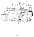
- the figure 1 represents the button (1) of the contactor according to the invention, for a module configuration.
- the actuating lever (13) protrudes from said upper face (15) of the base (14) of the button (1), while the other aforementioned elements (3, 17, 11, 9, 10, 12) protrude from the lower face (16) of the base (14) of the button (1) at the side edges.
- the antivibration blade (11) is located under a lateral edge of the base (14) of the button (1), and is protected by an element (12) to prevent deterioration during storage of the button (1).
- the return blade (3) is aligned under the opposite lateral edge of the button (1), and the stop (10) is located to cross the path of the return blade (3) under the same side edge .
- the element (9) is also located on this side and its role is to protect the return blade (3) during storage of the button (1), before mounting the contactor.
- Each side edge accommodates one of the two fins (17) symmetrically positioned under the button (1) relative to the longitudinal median axis of the base (14) of said button (1).
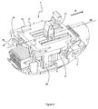
- the figure 2 represents the button (1) set up within the switch, in the automatic on position.
- the button (1) is movable in translation in the direction (D) as shown in the figure.
- This figure shows the side of the button (1) where the antivibration blade (11) is located. The latter is at rest, the button (1) being in the automatic position.
- this antivibration flexible blade (11) is connected to the lower face (16) of the base (14) of the button (1) via a tab (20) with a shape perpendicular to the direction moving the button (1).
- the antivibration blade (11) is oriented inclined with respect to the direction of movement of the button (1) and faces the movable contact holder (2).
- the figure 3 represents the button (1) in the forced on position.
- the contact In this mode of operation, the contact must be established between the fixed contacts and the moving contacts, without the activation of the magnetic circuit.
- the displacement (D) of the button (1) during the transition from the automatic position to the forced operation position causes the displacement of the contact carrier (2) in a direction perpendicular to that of the button (1) until at a stable position where the mobile and fixed contacts are closed. More specifically, during the transition, an inclined wall (23) of each fin (17) of the knob (1) comes into contact with an inclined wall (24) of the upper part of the contact holder (2).
- the upper face of the contact carrier (2) has a flat portion (21) and a slight recess (22) perpendicular to said flat portion (21).
- the mechanical attachment is performed when the tip (18) of each fin (17) of the button (1) is positioned beyond said recess (22). This attachment thus limits any displacement of the contact carrier (2) in the direction of movement (D) of the button (1).
- the contact between the fin (17) and the contact holder (2) also makes it possible to prevent any movement of the latter (2) in a direction perpendicular to the displacement (D) of the button (1), in the direction directed towards the button (1).
- the idea of the invention is also to limit or even eliminate the displacement of the contact carrier (2) in the same direction perpendicular to the displacement (D) of the button (1), but this time in the direction away from the contact carrier ( 2) of the button (1), by means of the antivibration blade (11).
- the latter is positioned to exert a constraint on a face of the contact carrier during the mechanical gripping phase (2).
- the free end of said antivibration blade (11) is positioned under a nose (25) of the contact holder (2) and exerts a force able to press the upper face of the contact holder (2) against the fins (17). ) of the button (1).
- This antivibration blade (11) thus adds a component oriented perpendicularly to the direction of movement (D) of the button (1), allowing the maintenance of the system in forced on position.
- the antivibration blade (11) is also designed to flex and allow the displacement of the contact holder (2) during the refilling of the coil of the contactor, allowing the return of the button (1) in the automatic position.
- the figure 4 represents the opposite side of the button (1) where the flexible return blade (3) is located.
- the button (1) is integrated in the contactor, the latter being in automatic operation.
- the flexible return blade (3) has an inverted L shape composed of a first section, or a short branch (7) parallel to the direction (D) of movement of the button (1), and a second section, or a long branch (6) of shape perpendicular to said direction (D), having the free end (4) of the flexible return blade (3).
- the short branch (7) is connected to the button (1) by a connecting section (8).
- the free end (4) of the return blade (3) cooperates with an abutment (5) integral with a fixed part of the switch during the transition from the automatic position to the forced on position.
- the figure 5 represents the button (1) positioned in the switch, in the forced on position. In this latter position, the flexible return blade (3) is deformed.
- the short branch (7) of the return blade (3) deflects towards the lower face (16) of the base (14). of the button (1) until the seat (19) of the angle of the L comes into contact with the stop (10) whose height is relatively small, and the long branch (6) of the return blade (3) undergoes a deflection increasing the angle between the two branches (6, 7).
- the figure 5 shows the deformation of these two branches (6, 7) when the button (1) is in the forced on position. In this position, the deformation is limited, and neither of the two branches (7, 6) enters the plastic domain.
- a return blade (3) as represented in FIG. figures 1 , 2 and 3 , decentered with respect to the transverse axis of the button (1), plays its role of reminding the forced position to the automatic position despite its tendency to rotate the knob (1).
- the return blade will therefore take another geometric shape capable of centering the forces relative to the transverse axis (X) of the button (1), as shown in FIG. figures 6 and 7 .
- the return blade (26) is Y-shaped, each leg (28, 29) of the fork cooperating with an abutment (30, 31) integral with a fixed part of the apparatus, the trunk ( 27) being attached to the underside (16) of the button (1).
- the return blade (26) is positioned so that the transverse axis (X) of the button (1) corresponds to the axis of symmetry of the blade (26). Its trunk (27) is then attached to the button (1) no longer on a lateral side but in the center of a side perpendicular to the direction of movement (D) of the button (1).
- the button (1) is in the automatic position and the return blade (26) is at rest.
- the button is in the forced on position, and the return blade (26) is solicited. Its two branches (28, 29), in contact with the two stops (31, 30), are deformed so as to reduce the angle of the fork.
- the blades (11, 3, 26), the stop (10) and the elements (12, 20, 9) form a single molded piece with the button (1).
Landscapes
- Physics & Mathematics (AREA)
- Electromagnetism (AREA)
- Rotary Switch, Piano Key Switch, And Lever Switch (AREA)
Claims (11)
- Elektromagnetisches Gerät vom Typ Tag-/Nacht-Schütz mit einem System zur manuellen Steuerung, umfassend einen Knopf (1), der mit mindestens einem mobilen Kontaktträger (2) zusammenarbeitet, der von der Aktivierung eines magnetischen Kreises oder von Rückstellmitteln des oder der Kontaktträger (2) angetrieben wird, wobei der Knopf (1) dazu ausgelegt ist, zwischen drei stabilen Positionen zu gleiten, die jeweils Folgendem entsprechen:- einer automatischen Funktion, in der das elektromagnetische Gerät vom magnetischen Kreis gesteuert wird;- einer Haltefunktion, die den magnetischen Kreis im Nebenschluss schaltet;- eine erzwungene Funktion des Verschlusses oder der Öffnung der Kontakte durch den Antrieb des mobilen Kontaktträgers (2) hin zu oder in einen Abstand von festen Kontakten und Beibehaltung in dieser Position durch mechanische Verankerungsmittel zwischen dem Knopf (1) und jedem Kontaktträger (2), wobei Rückstellmittel des Knopfes (1) zwischen dieser letzteren Position und der Position der automatischen Funktion vorgesehen sind,dadurch gekennzeichnet, dass der Knopf (1) Schwingungsschutzmittel (11) umfasst, die mit dem Kontaktträger (2) in der Position der erzwungenen Funktion zusammenarbeiten, wobei die Schwingungsschutzmittel aus mindestens einem flexiblen Schwingungsschutzblatt (11) pro mobilem Kontaktträger (2) besteht, geneigt mit Bezug auf die Richtung (D) der Verschiebung des Knopfes (1) ausgerichtet, und positioniert, um in der Phase der mechanischen Verankerung eine Spannung auf eine Seite des Kontaktträgers (2) auszuüben, dessen Bestandteil, der senkrecht auf die Verschiebungsrichtung des Knopfes (1) ausgerichtet ist, den Kontaktträger (2) gegen den Knopf (1) presst.
- Elektromagnetisches Gerät vom Typ Tag-/Nacht-Schütz mit einem System zur manuellen Steuerung nach dem vorhergehenden Anspruch, dadurch gekennzeichnet, dass das Schwingungsschutzblatt (11) einstückig mit dem Knopf (1) ist.
- Elektromagnetisches Gerät vom Typ Tag-/Nacht-Schütz mit einem System zur manuellen Steuerung nach Anspruch 1, dadurch gekennzeichnet, dass die Rückstellmittel zwischen der erzwungenen Position und der automatischen Position Teil des Knopfes (1) sind.
- Elektromagnetisches Gerät vom Typ Tag-/Nacht-Schütz mit einem System zur manuellen Steuerung nach dem vorhergehenden Anspruch, dadurch gekennzeichnet, dass die Rückstellmittel aus einem flexiblen Blatt (3) bestehen, das den Knopf (1) überragt, und von dem ein freies Ende (4) vorgesehen ist, um mit einem Anschlag (5) in Kontakt zu treten, der mit einem festen Teil des Geräts in der Phase der mechanischen Verankerung des Knopfes (1) mit dem mobilen Kontaktträger (2) fest verbunden ist.
- Elektromagnetisches Gerät vom Typ Tag-/Nacht-Schütz mit einem System zur manuellen Steuerung nach dem vorhergehenden Anspruch, dadurch gekennzeichnet, dass das flexible Rückstellblatt (3) eine Geometrie mit mindestens zwei Abschnitten (7, 6) aufweist, die eine doppelte Verformung ermöglichen.
- Elektromagnetisches Gerät vom Typ Tag-/Nacht-Schütz mit einem System zur manuellen Steuerung nach dem vorhergehenden Anspruch, dadurch gekennzeichnet, dass das flexible Blatt (3) einen ersten Abschnitt (7) mit parallelem Verlauf zur Richtung (D) der Verschiebung des Knopfes (1) umfasst, verbunden an diesen Letzteren durch einen Verbindungsabschnitt (8), und einen zweiten Abschnitt mit senkrechtem Verlauf (6) zu der Richtung (D), der das freie Ende (4) des flexiblen Rückstellblatts (3) umfasst.
- Elektromagnetisches Gerät vom Typ Tag-/Nacht-Schütz mit einem System zur manuellen Steuerung nach dem vorhergehenden Anspruch, dadurch gekennzeichnet, dass der Knopf (1) mit mindestens einem Anschlag (10) ausgestattet ist, der mit einem Abschnitt des flexiblen Rückstellblatts (3) zusammenarbeitet.
- Elektromagnetisches Gerät vom Typ Tag-/Nacht-Schütz mit einem System zur manuellen Steuerung nach einem der Ansprüche 4 und 5, dadurch gekennzeichnet, dass das flexible Rückstellblatt (3) in Form eines Y konfiguriert ist, wobei jeder Arm (28, 29) der Gabel mit einem Anschlag (30, 31) zusammenarbeitet, der mit einem festen Teil des Geräts in der Phase der mechanischen Verankerung des Knopfes (1) mit dem mobilen Kontaktträger (2) fest verbunden ist, wobei der Stumpf (27) mit dem Knopf (1) verbunden ist.
- Elektromagnetisches Gerät vom Typ Tag-/Nacht-Schütz mit einem System zur manuellen Steuerung nach einem der Ansprüche 5 bis 8, dadurch gekennzeichnet, dass die verschiedenen Abschnitte des flexiblen Rückstellblatts (3) einen im Wesentlichen konstanten Schnitt aufweisen.
- Elektromagnetisches Gerät vom Typ Tag-/Nacht-Schütz mit einem System zur manuellen Steuerung nach einem der Ansprüche 4 bis 9, dadurch gekennzeichnet, dass das flexible Rückstellblatt (3) einstückig mit dem Knopf (1) ist.
- Elektromagnetisches Gerät vom Typ Tag-/Nacht-Schütz mit einem System zur manuellen Steuerung nach dem vorhergehenden Anspruch, dadurch gekennzeichnet, dass der Knopf (1), ausgestattet mit dem flexiblen Rückstellblatt (3) und dem Schwingungsschutzblatt (11), ein aus Plastik geformter Teil ist.
Priority Applications (1)
| Application Number | Priority Date | Filing Date | Title |
|---|---|---|---|
| EP20100306044 EP2434518B1 (de) | 2010-09-28 | 2010-09-28 | Verbesserter Betätigungsknopf eines Schutzschalters |
Applications Claiming Priority (1)
| Application Number | Priority Date | Filing Date | Title |
|---|---|---|---|
| EP20100306044 EP2434518B1 (de) | 2010-09-28 | 2010-09-28 | Verbesserter Betätigungsknopf eines Schutzschalters |
Publications (2)
| Publication Number | Publication Date |
|---|---|
| EP2434518A1 EP2434518A1 (de) | 2012-03-28 |
| EP2434518B1 true EP2434518B1 (de) | 2013-04-17 |
Family
ID=43608808
Family Applications (1)
| Application Number | Title | Priority Date | Filing Date |
|---|---|---|---|
| EP20100306044 Active EP2434518B1 (de) | 2010-09-28 | 2010-09-28 | Verbesserter Betätigungsknopf eines Schutzschalters |
Country Status (1)
| Country | Link |
|---|---|
| EP (1) | EP2434518B1 (de) |
Family Cites Families (3)
| Publication number | Priority date | Publication date | Assignee | Title |
|---|---|---|---|---|
| FR2686189B1 (fr) * | 1992-01-14 | 1994-04-15 | Hager Electro Sa | Perfectionnement aux appareils interrupteurs a commande electromagnetique et manuelle, tels que relais, contacteurs ou contacteurs jour-nuit. |
| EP0645792B1 (de) * | 1993-09-27 | 1995-06-07 | Hager Electro S.A. | Lichtbogenkammern begrenzendes Teil |
| FR2735612B1 (fr) * | 1995-06-13 | 1997-09-12 | Hager Electro | Perfectionnement aux contacteurs electriques |
-
2010
- 2010-09-28 EP EP20100306044 patent/EP2434518B1/de active Active
Also Published As
| Publication number | Publication date |
|---|---|
| EP2434518A1 (de) | 2012-03-28 |
Similar Documents
| Publication | Publication Date | Title |
|---|---|---|
| CA2001670C (fr) | Dispositif de securite pour appareil de commutation realise par l'assemblage de plusieurs elements modulaires amovibles | |
| EP1135045B1 (de) | Elektrischer toaster mit einer elektromagnetischen schalteinheit | |
| EP2434518B1 (de) | Verbesserter Betätigungsknopf eines Schutzschalters | |
| EP3261105B1 (de) | Elektrisches gerät zum leitungsschutz | |
| EP3993001B1 (de) | Beweglicher kontaktträger für einen stromkreisunterbrecher und stromkreisunterbrecher mit einem solchen beweglichen kontaktträger | |
| FR2849761A3 (fr) | Grille-pain electrique | |
| EP3813089B1 (de) | Elektrischer minischalter vom typ normalerweise geschlossen, mit einer verriegelungsposition des offenem kontaktes | |
| EP1815569B1 (de) | Überspannungsschutzeinrichtung mit verbesserter trennung | |
| EP3341519B1 (de) | Elektrisches haushaltsgerät umfassend eine über einen thermostat mit einem thermischen regelkreis versorgte, beheizte platte | |
| FR2813988A1 (fr) | Dispositif de coupure d'un appareil interrupteur | |
| EP1632970B1 (de) | Elektromagnetische Auslöser und elektronischer Schutzschalter, die es enthält. | |
| FR2919751A1 (fr) | Dispositif de commande electrique | |
| EP1248277A1 (de) | Elektromagnetischer Auslöser mit einer flexiblen Trägereinrichtung für einen elektromagnetischen Kreis und einen elektromagnetischen Auslöser mit einer schwebenden Spule | |
| EP0180693A2 (de) | Schalter zum automatischen Einschalten eines Hausheizungskessels mit elektrischen Heizeinrichtungen an eine elektrische Energieverteilungsleitung | |
| EP2381824B1 (de) | Verbinder für einen getränkezubereitungsautomat | |
| EP2750158B1 (de) | Magnetische und thermische Untereinheit für selektiven Schutzschalter | |
| EP1248278B1 (de) | Elektromagnetischer Auslöser mit einem elektromagnetischen Kreis und mit einem Anker mit drei stabilen Positionen | |
| EP1650780A1 (de) | Elektromechanischer Auslöser und elektronisches Schutzgerät mit letzterem | |
| EP1756917B1 (de) | System zur automatischen verbindung zweier stromkreise eines fahrzeuges | |
| EP1006549A1 (de) | Elektromechanisches Schaltgerät | |
| FR2823370A1 (fr) | Declencheur electromagnetique comprenant une armature mobile et une armature fixe sur laquelle est encliquetee une piece de guidage de l'armature mobile | |
| FR3107393A1 (fr) | Commutateur electrique du type normalement ferme comportant un etat initial de livraison a contact ouvert | |
| FR2641642A1 (fr) | Interrupteur a rupture brusque et a securite positive d'ouverture | |
| EP3506025A1 (de) | Steuervorrichtung mindestens einer elektronischen funktion eines tragbaren geräts | |
| FR2541505A3 (fr) | Commutateur sensible a une pression |
Legal Events
| Date | Code | Title | Description |
|---|---|---|---|
| PUAI | Public reference made under article 153(3) epc to a published international application that has entered the european phase |
Free format text: ORIGINAL CODE: 0009012 |
|
| AK | Designated contracting states |
Kind code of ref document: A1 Designated state(s): AL AT BE BG CH CY CZ DE DK EE ES FI FR GB GR HR HU IE IS IT LI LT LU LV MC MK MT NL NO PL PT RO SE SI SK SM TR |
|
| AX | Request for extension of the european patent |
Extension state: BA ME RS |
|
| GRAP | Despatch of communication of intention to grant a patent |
Free format text: ORIGINAL CODE: EPIDOSNIGR1 |
|
| 17P | Request for examination filed |
Effective date: 20120927 |
|
| GRAS | Grant fee paid |
Free format text: ORIGINAL CODE: EPIDOSNIGR3 |
|
| GRAA | (expected) grant |
Free format text: ORIGINAL CODE: 0009210 |
|
| AK | Designated contracting states |
Kind code of ref document: B1 Designated state(s): AL AT BE BG CH CY CZ DE DK EE ES FI FR GB GR HR HU IE IS IT LI LT LU LV MC MK MT NL NO PL PT RO SE SI SK SM TR |
|
| REG | Reference to a national code |
Ref country code: GB Ref legal event code: FG4D Free format text: NOT ENGLISH |
|
| REG | Reference to a national code |
Ref country code: CH Ref legal event code: EP |
|
| REG | Reference to a national code |
Ref country code: IE Ref legal event code: FG4D Free format text: LANGUAGE OF EP DOCUMENT: FRENCH |
|
| REG | Reference to a national code |
Ref country code: AT Ref legal event code: REF Ref document number: 607761 Country of ref document: AT Kind code of ref document: T Effective date: 20130515 |
|
| REG | Reference to a national code |
Ref country code: DE Ref legal event code: R096 Ref document number: 602010006271 Country of ref document: DE Effective date: 20130613 |
|
| REG | Reference to a national code |
Ref country code: AT Ref legal event code: MK05 Ref document number: 607761 Country of ref document: AT Kind code of ref document: T Effective date: 20130417 |
|
| REG | Reference to a national code |
Ref country code: LT Ref legal event code: MG4D |
|
| REG | Reference to a national code |
Ref country code: NL Ref legal event code: VDEP Effective date: 20130417 |
|
| PG25 | Lapsed in a contracting state [announced via postgrant information from national office to epo] |
Ref country code: GR Free format text: LAPSE BECAUSE OF FAILURE TO SUBMIT A TRANSLATION OF THE DESCRIPTION OR TO PAY THE FEE WITHIN THE PRESCRIBED TIME-LIMIT Effective date: 20130718 Ref country code: AT Free format text: LAPSE BECAUSE OF FAILURE TO SUBMIT A TRANSLATION OF THE DESCRIPTION OR TO PAY THE FEE WITHIN THE PRESCRIBED TIME-LIMIT Effective date: 20130417 Ref country code: SE Free format text: LAPSE BECAUSE OF FAILURE TO SUBMIT A TRANSLATION OF THE DESCRIPTION OR TO PAY THE FEE WITHIN THE PRESCRIBED TIME-LIMIT Effective date: 20130417 Ref country code: ES Free format text: LAPSE BECAUSE OF FAILURE TO SUBMIT A TRANSLATION OF THE DESCRIPTION OR TO PAY THE FEE WITHIN THE PRESCRIBED TIME-LIMIT Effective date: 20130728 Ref country code: LT Free format text: LAPSE BECAUSE OF FAILURE TO SUBMIT A TRANSLATION OF THE DESCRIPTION OR TO PAY THE FEE WITHIN THE PRESCRIBED TIME-LIMIT Effective date: 20130417 Ref country code: NO Free format text: LAPSE BECAUSE OF FAILURE TO SUBMIT A TRANSLATION OF THE DESCRIPTION OR TO PAY THE FEE WITHIN THE PRESCRIBED TIME-LIMIT Effective date: 20130717 Ref country code: FI Free format text: LAPSE BECAUSE OF FAILURE TO SUBMIT A TRANSLATION OF THE DESCRIPTION OR TO PAY THE FEE WITHIN THE PRESCRIBED TIME-LIMIT Effective date: 20130417 Ref country code: SI Free format text: LAPSE BECAUSE OF FAILURE TO SUBMIT A TRANSLATION OF THE DESCRIPTION OR TO PAY THE FEE WITHIN THE PRESCRIBED TIME-LIMIT Effective date: 20130417 Ref country code: PT Free format text: LAPSE BECAUSE OF FAILURE TO SUBMIT A TRANSLATION OF THE DESCRIPTION OR TO PAY THE FEE WITHIN THE PRESCRIBED TIME-LIMIT Effective date: 20130819 Ref country code: IS Free format text: LAPSE BECAUSE OF FAILURE TO SUBMIT A TRANSLATION OF THE DESCRIPTION OR TO PAY THE FEE WITHIN THE PRESCRIBED TIME-LIMIT Effective date: 20130817 |
|
| PG25 | Lapsed in a contracting state [announced via postgrant information from national office to epo] |
Ref country code: HR Free format text: LAPSE BECAUSE OF FAILURE TO SUBMIT A TRANSLATION OF THE DESCRIPTION OR TO PAY THE FEE WITHIN THE PRESCRIBED TIME-LIMIT Effective date: 20130417 Ref country code: BG Free format text: LAPSE BECAUSE OF FAILURE TO SUBMIT A TRANSLATION OF THE DESCRIPTION OR TO PAY THE FEE WITHIN THE PRESCRIBED TIME-LIMIT Effective date: 20130717 Ref country code: LV Free format text: LAPSE BECAUSE OF FAILURE TO SUBMIT A TRANSLATION OF THE DESCRIPTION OR TO PAY THE FEE WITHIN THE PRESCRIBED TIME-LIMIT Effective date: 20130417 Ref country code: CY Free format text: LAPSE BECAUSE OF FAILURE TO SUBMIT A TRANSLATION OF THE DESCRIPTION OR TO PAY THE FEE WITHIN THE PRESCRIBED TIME-LIMIT Effective date: 20130417 Ref country code: PL Free format text: LAPSE BECAUSE OF FAILURE TO SUBMIT A TRANSLATION OF THE DESCRIPTION OR TO PAY THE FEE WITHIN THE PRESCRIBED TIME-LIMIT Effective date: 20130417 |
|
| PG25 | Lapsed in a contracting state [announced via postgrant information from national office to epo] |
Ref country code: CZ Free format text: LAPSE BECAUSE OF FAILURE TO SUBMIT A TRANSLATION OF THE DESCRIPTION OR TO PAY THE FEE WITHIN THE PRESCRIBED TIME-LIMIT Effective date: 20130417 Ref country code: SK Free format text: LAPSE BECAUSE OF FAILURE TO SUBMIT A TRANSLATION OF THE DESCRIPTION OR TO PAY THE FEE WITHIN THE PRESCRIBED TIME-LIMIT Effective date: 20130417 Ref country code: DK Free format text: LAPSE BECAUSE OF FAILURE TO SUBMIT A TRANSLATION OF THE DESCRIPTION OR TO PAY THE FEE WITHIN THE PRESCRIBED TIME-LIMIT Effective date: 20130417 Ref country code: EE Free format text: LAPSE BECAUSE OF FAILURE TO SUBMIT A TRANSLATION OF THE DESCRIPTION OR TO PAY THE FEE WITHIN THE PRESCRIBED TIME-LIMIT Effective date: 20130417 |
|
| PLBE | No opposition filed within time limit |
Free format text: ORIGINAL CODE: 0009261 |
|
| STAA | Information on the status of an ep patent application or granted ep patent |
Free format text: STATUS: NO OPPOSITION FILED WITHIN TIME LIMIT |
|
| PG25 | Lapsed in a contracting state [announced via postgrant information from national office to epo] |
Ref country code: NL Free format text: LAPSE BECAUSE OF FAILURE TO SUBMIT A TRANSLATION OF THE DESCRIPTION OR TO PAY THE FEE WITHIN THE PRESCRIBED TIME-LIMIT Effective date: 20130417 Ref country code: RO Free format text: LAPSE BECAUSE OF FAILURE TO SUBMIT A TRANSLATION OF THE DESCRIPTION OR TO PAY THE FEE WITHIN THE PRESCRIBED TIME-LIMIT Effective date: 20130417 Ref country code: IT Free format text: LAPSE BECAUSE OF FAILURE TO SUBMIT A TRANSLATION OF THE DESCRIPTION OR TO PAY THE FEE WITHIN THE PRESCRIBED TIME-LIMIT Effective date: 20130417 |
|
| 26N | No opposition filed |
Effective date: 20140120 |
|
| BERE | Be: lapsed |
Owner name: HAGER-ELECTRO SAS Effective date: 20130930 |
|
| PG25 | Lapsed in a contracting state [announced via postgrant information from national office to epo] |
Ref country code: MC Free format text: LAPSE BECAUSE OF FAILURE TO SUBMIT A TRANSLATION OF THE DESCRIPTION OR TO PAY THE FEE WITHIN THE PRESCRIBED TIME-LIMIT Effective date: 20130417 |
|
| REG | Reference to a national code |
Ref country code: DE Ref legal event code: R097 Ref document number: 602010006271 Country of ref document: DE Effective date: 20140120 |
|
| REG | Reference to a national code |
Ref country code: IE Ref legal event code: MM4A |
|
| PG25 | Lapsed in a contracting state [announced via postgrant information from national office to epo] |
Ref country code: BE Free format text: LAPSE BECAUSE OF NON-PAYMENT OF DUE FEES Effective date: 20130930 Ref country code: IE Free format text: LAPSE BECAUSE OF NON-PAYMENT OF DUE FEES Effective date: 20130928 |
|
| REG | Reference to a national code |
Ref country code: CH Ref legal event code: NV Representative=s name: RENTSCH PARTNER AG, CH |
|
| GBPC | Gb: european patent ceased through non-payment of renewal fee |
Effective date: 20140928 |
|
| PG25 | Lapsed in a contracting state [announced via postgrant information from national office to epo] |
Ref country code: SM Free format text: LAPSE BECAUSE OF FAILURE TO SUBMIT A TRANSLATION OF THE DESCRIPTION OR TO PAY THE FEE WITHIN THE PRESCRIBED TIME-LIMIT Effective date: 20130417 |
|
| PG25 | Lapsed in a contracting state [announced via postgrant information from national office to epo] |
Ref country code: TR Free format text: LAPSE BECAUSE OF FAILURE TO SUBMIT A TRANSLATION OF THE DESCRIPTION OR TO PAY THE FEE WITHIN THE PRESCRIBED TIME-LIMIT Effective date: 20130417 Ref country code: MT Free format text: LAPSE BECAUSE OF FAILURE TO SUBMIT A TRANSLATION OF THE DESCRIPTION OR TO PAY THE FEE WITHIN THE PRESCRIBED TIME-LIMIT Effective date: 20130417 |
|
| PG25 | Lapsed in a contracting state [announced via postgrant information from national office to epo] |
Ref country code: LU Free format text: LAPSE BECAUSE OF NON-PAYMENT OF DUE FEES Effective date: 20130928 Ref country code: HU Free format text: LAPSE BECAUSE OF FAILURE TO SUBMIT A TRANSLATION OF THE DESCRIPTION OR TO PAY THE FEE WITHIN THE PRESCRIBED TIME-LIMIT; INVALID AB INITIO Effective date: 20100928 Ref country code: GB Free format text: LAPSE BECAUSE OF NON-PAYMENT OF DUE FEES Effective date: 20140928 Ref country code: MK Free format text: LAPSE BECAUSE OF FAILURE TO SUBMIT A TRANSLATION OF THE DESCRIPTION OR TO PAY THE FEE WITHIN THE PRESCRIBED TIME-LIMIT Effective date: 20130417 |
|
| REG | Reference to a national code |
Ref country code: FR Ref legal event code: PLFP Year of fee payment: 7 |
|
| REG | Reference to a national code |
Ref country code: FR Ref legal event code: PLFP Year of fee payment: 8 |
|
| REG | Reference to a national code |
Ref country code: CH Ref legal event code: PCAR Free format text: NEW ADDRESS: BELLERIVESTRASSE 203 POSTFACH, 8034 ZUERICH (CH) |
|
| REG | Reference to a national code |
Ref country code: FR Ref legal event code: PLFP Year of fee payment: 9 |
|
| PG25 | Lapsed in a contracting state [announced via postgrant information from national office to epo] |
Ref country code: AL Free format text: LAPSE BECAUSE OF FAILURE TO SUBMIT A TRANSLATION OF THE DESCRIPTION OR TO PAY THE FEE WITHIN THE PRESCRIBED TIME-LIMIT Effective date: 20130417 |
|
| P01 | Opt-out of the competence of the unified patent court (upc) registered |
Effective date: 20230606 |
|
| PGFP | Annual fee paid to national office [announced via postgrant information from national office to epo] |
Ref country code: DE Payment date: 20240927 Year of fee payment: 15 |
|
| PGFP | Annual fee paid to national office [announced via postgrant information from national office to epo] |
Ref country code: FR Payment date: 20240925 Year of fee payment: 15 |
|
| PGFP | Annual fee paid to national office [announced via postgrant information from national office to epo] |
Ref country code: CH Payment date: 20241002 Year of fee payment: 15 |