EP4240998B1 - Valve cavity cap arrangements - Google Patents
Valve cavity cap arrangements Download PDFInfo
- Publication number
- EP4240998B1 EP4240998B1 EP21815792.3A EP21815792A EP4240998B1 EP 4240998 B1 EP4240998 B1 EP 4240998B1 EP 21815792 A EP21815792 A EP 21815792A EP 4240998 B1 EP4240998 B1 EP 4240998B1
- Authority
- EP
- European Patent Office
- Prior art keywords
- cap
- insert
- central
- annular sealing
- valve cavity
- Prior art date
- Legal status (The legal status is an assumption and is not a legal conclusion. Google has not performed a legal analysis and makes no representation as to the accuracy of the status listed.)
- Active
Links
Images


Classifications
-
- F—MECHANICAL ENGINEERING; LIGHTING; HEATING; WEAPONS; BLASTING
- F16—ENGINEERING ELEMENTS AND UNITS; GENERAL MEASURES FOR PRODUCING AND MAINTAINING EFFECTIVE FUNCTIONING OF MACHINES OR INSTALLATIONS; THERMAL INSULATION IN GENERAL
- F16K—VALVES; TAPS; COCKS; ACTUATING-FLOATS; DEVICES FOR VENTING OR AERATING
- F16K27/00—Construction of housing; Use of materials therefor
- F16K27/003—Housing formed from a plurality of the same valve elements
-
- F—MECHANICAL ENGINEERING; LIGHTING; HEATING; WEAPONS; BLASTING
- F16—ENGINEERING ELEMENTS AND UNITS; GENERAL MEASURES FOR PRODUCING AND MAINTAINING EFFECTIVE FUNCTIONING OF MACHINES OR INSTALLATIONS; THERMAL INSULATION IN GENERAL
- F16K—VALVES; TAPS; COCKS; ACTUATING-FLOATS; DEVICES FOR VENTING OR AERATING
- F16K27/00—Construction of housing; Use of materials therefor
- F16K27/02—Construction of housing; Use of materials therefor of lift valves
- F16K27/0236—Diaphragm cut-off apparatus
-
- F—MECHANICAL ENGINEERING; LIGHTING; HEATING; WEAPONS; BLASTING
- F16—ENGINEERING ELEMENTS AND UNITS; GENERAL MEASURES FOR PRODUCING AND MAINTAINING EFFECTIVE FUNCTIONING OF MACHINES OR INSTALLATIONS; THERMAL INSULATION IN GENERAL
- F16K—VALVES; TAPS; COCKS; ACTUATING-FLOATS; DEVICES FOR VENTING OR AERATING
- F16K27/00—Construction of housing; Use of materials therefor
- F16K27/08—Guiding yokes for spindles; Means for closing housings; Dust caps, e.g. for tyre valves
-
- F—MECHANICAL ENGINEERING; LIGHTING; HEATING; WEAPONS; BLASTING
- F16—ENGINEERING ELEMENTS AND UNITS; GENERAL MEASURES FOR PRODUCING AND MAINTAINING EFFECTIVE FUNCTIONING OF MACHINES OR INSTALLATIONS; THERMAL INSULATION IN GENERAL
- F16L—PIPES; JOINTS OR FITTINGS FOR PIPES; SUPPORTS FOR PIPES, CABLES OR PROTECTIVE TUBING; MEANS FOR THERMAL INSULATION IN GENERAL
- F16L55/00—Devices or appurtenances for use in, or in connection with, pipes or pipe systems
- F16L55/10—Means for stopping flow in pipes or hoses
- F16L55/11—Plugs
- F16L55/1108—Plugs fixed by screwing or by means of a screw-threaded ring
-
- F—MECHANICAL ENGINEERING; LIGHTING; HEATING; WEAPONS; BLASTING
- F16—ENGINEERING ELEMENTS AND UNITS; GENERAL MEASURES FOR PRODUCING AND MAINTAINING EFFECTIVE FUNCTIONING OF MACHINES OR INSTALLATIONS; THERMAL INSULATION IN GENERAL
- F16K—VALVES; TAPS; COCKS; ACTUATING-FLOATS; DEVICES FOR VENTING OR AERATING
- F16K7/00—Diaphragm valves or cut-off apparatus, e.g. with a member deformed, but not moved bodily, to close the passage ; Pinch valves
- F16K7/12—Diaphragm valves or cut-off apparatus, e.g. with a member deformed, but not moved bodily, to close the passage ; Pinch valves with flat, dished, or bowl-shaped diaphragm
- F16K7/14—Diaphragm valves or cut-off apparatus, e.g. with a member deformed, but not moved bodily, to close the passage ; Pinch valves with flat, dished, or bowl-shaped diaphragm arranged to be deformed against a flat seat
- F16K7/16—Diaphragm valves or cut-off apparatus, e.g. with a member deformed, but not moved bodily, to close the passage ; Pinch valves with flat, dished, or bowl-shaped diaphragm arranged to be deformed against a flat seat the diaphragm being mechanically actuated, e.g. by screw-spindle or cam
Definitions
- the inventions relate to fluid flow and delivery devices and methods, and more particularly to valves used to control fluid flow and delivery.
- Valves are well known for use as flow control devices for gas and liquid fluid delivery.
- delivery of process chemicals during various processing operations is controlled using valves, for example, high purity valves.
- Exemplary applications for valves used in the semiconductor industry include chemical vapor deposition (CVD) and atomic layer deposition (ALD). In many applications, rapid precise control of the amount of fluid supplied is required.
- CVD chemical vapor deposition
- ALD atomic layer deposition
- a valve cavity cap arrangement in combination with a valve body defining a valve cavity having a recessed surface from which a central passage and at least one radially offset passage extend.
- the valve cavity cap arrangement includes an insert and a threaded cap.
- the insert is received in the valve cavity and includes an inner annular sealing surface sized to seal against a portion of the recessed surface surrounding the central passage, an outer annular sealing surface sized to seal against an outer periphery of the recessed surface, surrounding the at least one radially offset passage, and a solid web portion extending between the inner annular sealing surface and the outer annular sealing surface.
- the threaded cap includes an outer threaded portion threadably engaged with an internal threaded portion of the valve cavity, a central end portion configured to apply a first sealing force to the inner annular sealing surface, and an outer end portion configured to apply a second sealing force to the outer annular sealing surface.
- a method of sealing a valve cavity is contemplated, with the valve cavity including a recessed surface from which a central passage and at least one radially offset passage extend.
- an insert is installed in the valve cavity, such that an inner annular sealing surface of the insert engages a portion of the recessed surface surrounding the central passage and an outer annular sealing surface of the insert engages an outer periphery of the recessed surface, surrounding the at least one radially offset passage.
- a cap is assembled with the valve cavity, such that a central end portion of the cap applies a first sealing force to the inner annular sealing surface, and an outer end portion of the cap applies a second sealing force to the outer annular sealing surface.
- Diaphragm valves are used as flow control devices for gas and liquid fluids.
- process system gases are controlled using diaphragm valves.
- a diaphragm valve may be installed into a process system in many different ways, including being mounted on manifolds or substrates that use surface mount technology.
- a manifold body block 16 includes a plurality of internally threaded valve cavities 32 each defining a recessed surface 34 from which a central passage 36 and at least one radially offset passage 38 extend.
- a seat carrier subassembly 42 is installed in each valve cavity 32, and includes a seat carrier 44 defining a central opening 56 aligned with the central passage 36, and outer openings 92 substantially aligned with (e.g., at least partially radially aligned with) the at least one offset passage 38.
- An outer rim 46 of the seat carrier 44 supports (and may be welded to) a diaphragm 26 with the diaphragm and outer rim being clamped between the valve cavity recessed surface 34 and a bonnet nut 78 threaded into the valve cavity 32 to retain the seat carrier subassembly 78 and to provide for threaded assembly of an actuator assembly 14.
- a body seal 70 surrounds the central opening 56 and seals against the recessed surface 34 around the central passage 36, and a valve seat 40 (which may be integral with the body seal 70) surrounds the central opening 56 and seals against the diaphragm 26 to block flow between the central and offset passages 36, 38 when the diaphragm is in a closed (e.g., downward) position.
- the offset passages may be open to each other in the diaphragm's closed position, for example, to maintain flow through a fluid system, with the central passage providing for fluid sampling or injection when the diaphragm is in an open position.
- US5881997A discloses another example of a flow control valve.
- a cap may be installed in place of the valve.
- a flow-through cap may provide a means for the flow to pass continuously through the installed location, as if the valve cavity/position were provided with a valve that is always in an open position.
- a valve cavity cap arrangement provides a first metal-to-metal seal portion around a central passage extending to the valve cavity to block flow between the central passage and one or more outer radial passages, and an independent second seal portion around an outer periphery of the valve cavity, to prevent shell leakage of fluid in the outer radial passage(s).
- a valve cavity cap arrangement 100 includes a seal cartridge or insert 110 sized to be received in a valve cavity 32 of a valve body (e.g., manifold body 16), and a threaded cap 120 having an outer threaded portion 129 threadably engageable with the internal threaded portion 82 of the valve cavity.
- the exemplary insert 110 includes a solid central portion 111 surrounded by an inner annular sealing bead 112 sized to seal against a central passage seal portion 34a of the recessed surface 34 surrounding the central passage 36, to block fluid flow to and/or from the central passage.
- a solid web portion 113 of the insert 110 extends between the inner annular sealing surface 112 and an outer annular sealing bead 114 sized to seal against an outer periphery seal portion 34b of the recessed surface 34, surrounding the offset passage(s) 38, 39 to provide a seal around the offset passage(s), while maintaining fluid communication between the offset passages 38, 39, in embodiments having more than one offset passage.
- the insert 110 is metal (e.g., stainless steel) to provide a metal-to-metal seal between the valve cavity and the insert.
- annular may include circular or any other suitable surrounding shape (e.g., oblong, elliptical, etc.).
- the threaded cap 120 includes a central end portion 122 configured to engage a central bearing surface 117 of the insert 110 to apply a first sealing force to the inner annular sealing surface 112 and an outer end portion 124 (e.g., an annular sealing surface) configured to engage an outer bearing surface 118 of the insert to apply a second sealing force to the outer annular sealing surface 114.
- a central end portion 122 configured to engage a central bearing surface 117 of the insert 110 to apply a first sealing force to the inner annular sealing surface 112
- an outer end portion 124 e.g., an annular sealing surface
- the cap 120 is a two-piece configuration having an inner cap plug 121 defining the central end portion 122 assembled with an outer cap nut 123 defining the outer end portion 124, for example, by threaded engagement between an outer threaded portion 125 of the cap plug 121 and an inner threaded portion 126 of the cap nut 123.
- the cap plug 121 may be threadably adjusted within the cap nut 123 for independent adjustment of the first and second sealing forces. Tightening adjustments of the cap plug 121 and the cap nut 123 may be made, for example, based on tightening torque or incremental turns from a snug tight condition. As shown in FIG.
- the cap plug 121 and the cap nut 123 may include outer grippable portions 121a, 123a to facilitate tightening with a tool (e.g., wrench flats 121a) or user hand grip (e.g., contoured hand grip portions 123a), and the cap nut 123 may be provided with one or more vent ports 127, for example, to detect leakage past the insert 110.
- a tool e.g., wrench flats 121a
- user hand grip e.g., contoured hand grip portions 123a
- vent ports 127 for example, to detect leakage past the insert 110.
- a web portion 113 having a thickness between about 0.508 mm (0.020") and about 1.524 mm (0.060”), or about 0.762 mm (0.030") may be used to provide web deflection sufficient to accommodate a seal offset (e.g., due to dimensional tolerances in the valve cavity seal surfaces and/or the annular sealing surface surfaces) of up to about 0.254 mm (0.010").
- a seal offset e.g., due to dimensional tolerances in the valve cavity seal surfaces and/or the annular sealing surface surfaces
- even thicker web portions may still allow for independent loading of the outer and inner annular sealing surfaces 114, 112 by the cap nut 123 and cap plug 121.
- the web portion 113 is substantially coplanar with the insert bearing surfaces 117, 118, for example, to provide an enlarged space between the valve cavity recessed surface 34 and the web portion 113 to maximize flow between the offset passages 38, 39, in embodiments having more than one offset passage.
- the insert 110' may include a web portion 113' that is more centrally positioned axially between the upper bearing surfaces 117', 118' and the lower annular sealing surfaces 112', 114', for example, to provide increased flexibility between the outer and inner sealing beads, for example, in embodiments for which flow capacity is less critical or where only one offset passage is provided.
- a valve cavity cap arrangement may include a flow diverting cartridge or insert having a central passage extending through the cap, for example, for connection with a flow loop or other flow control arrangement.
- a valve cavity cap arrangement 200 includes a flow diverting cartridge or insert 210 sized to be received in a valve cavity 32 of a manifold body 16, and a threaded cap 220 having an outer threaded portion 229 threadably engageable with the internal threaded portion 82 of the valve cavity.
- the exemplary insert 210 includes a tubular extension 215 extending from an apertured central portion 211, which is surrounded by an inner annular sealing surface 212 sized to seal against a seal portion 34a of the recessed surface 34 surrounding the central passage 36.
- the apertured central portion 211 includes a central port 216 that extends from the tubular extension 215 to an end surface of the insert, radially inward of the inner annular sealing surface 212, to provide a fluid passage between the central passage 36 and the tubular extension 215.
- a solid web portion 213 of the insert 210 extends between the inner annular sealing surface 212 and an outer annular sealing surface 214 sized to seal against an outer periphery 34b of the recessed surface 34, surrounding the offset passage(s) 38, 39, to provide a seal around the offset passage(s), while maintaining fluid communication between the offset passages 38, 39, in embodiments having more than one offset passage.
- the insert 210 is metal (e.g., stainless steel) to provide a metal-to-metal seal between the valve cavity 32 and the insert 210.
- the threaded cap 220 includes a central end portion 222 defining a central bore 228, receiving the tubular extension 215 of the insert 210 therethrough, surrounded by an annular end face 222a configured to apply a first sealing force to the inner annular sealing surface 212, and an outer end portion 224 configured to apply a second sealing force to the outer annular sealing surface 214.
- the cap 220 is a two-piece configuration having an inner cap plug 221, defining the central end portion 222, assembled with, and axially adjustable with respect to, an outer cap nut 223 defining the outer end portion 224, for example, by threaded engagement between an outer threaded portion 225 of the cap plug 221 and an inner threaded portion 226 of the cap nut 223.
- the cap plug 221 may be threadably adjusted within the cap nut 223 for independent axial adjustment of the first and second sealing forces. Tightening adjustments of the cap plug 221 and the cap nut 223 may be made, for example, based on tightening torque or incremental turns from a snug tight condition.
- the cap plug 221 and the cap nut 223 may include outer grippable portions 221a, 223a to facilitate tightening with a tool (e.g., wrench flats 221a) or user hand grip (e.g., contoured hand grip portions 223a), and the cap nut 223 may be provided with one or more vent ports 227, for example, to detect leakage past the insert 210.
- a tool e.g., wrench flats 221a
- user hand grip e.g., contoured hand grip portions 223a
- vent ports 227 for example, to detect leakage past the insert 210.
- the web portion 213 of the insert 210 may be thin enough to provide a degree of axial flexing between the outer and inner sealing beads so that differences in the valve cavity recessed surface can be accommodated and the load transfer from outer to inner seal is minimized, for example, similar to the web portion 113 of the insert 110 of FIG. 3 , as described above.
- the web portion 213 is substantially coplanar with the outer bearing surface 218, for example, to provide an enlarged space between the valve cavity recessed surface 34 and the web portion 213 to maximize flow between the offset passages 38, 39.
- the insert 210' may include a web portion 213' that is more centrally positioned between the upper bearing surfaces 217', 218' and the lower annular sealing surfaces 212', 214', for example, to provide increased flexibility between the outer and inner sealing beads, for example, in embodiments for which flow capacity is less critical or where only one offset passage is provided.
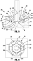
- a valve cavity cap arrangement may include a flow diverting cartridge or insert having a radially offset passage extending through the cap, for example, for connection with a flow loop or other flow control arrangement.
- a valve cavity cap arrangement 300 includes a flow diverting cartridge or insert 310 sized to be received in a valve cavity 32 of a manifold body 16, and a threaded cap 320 having an outer threaded portion 329 threadably engageable with the internal threaded portion 82 of the valve cavity.
- the exemplary insert 310 includes a tubular extension 315 extending from a solid central portion 311 surrounded by an inner annular sealing surface 312 sized to seal against a seal portion 34a of the recessed surface 34 surrounding the central passage 36, to block flow to and/or from the central passage 36.
- the insert 310 includes one or more ports 316 extending radially outward and axially downward from the tubular extension 315 to an end surface of the insert, radially outward of the inner annular sealing surface 312, to provide one or more fluid passages between the offset passage(s) 38, 39 and the tubular extension 315.
- a solid web portion 313 of the insert 310 extends between the ports 316 and an outer annular sealing surface 314 sized to seal against an outer periphery 34b of the recessed surface 34, surrounding the offset passage(s) 38, 39, to provide a seal around the offset passage(s), while maintaining fluid communication between the offset passages 38, 39, in embodiments having more than one offset passage.
- the insert 310 is metal (e.g., stainless steel) to provide a metal-to-metal seal between the valve cavity and the insert.
- the threaded cap 320 includes a central end portion 322 defining a central bore 328, receiving the tubular central portion 311 of the insert 310 therethrough, surrounded by an annular end face 322a configured to apply a first sealing force to the inner annular sealing surface 312, and an outer end portion 324 configured to apply a second sealing force to the outer annular sealing surface 314.
- the cap 320 is a two-piece configuration having an inner cap plug 321 defining the central end portion 322 assembled with, and axially adjustable with respect to, an outer cap nut 323 defining the outer end portion 324, for example, by threaded engagement between an outer threaded portion 325 of the cap plug 321 and an inner threaded portion 326 of the cap nut 323.
- the cap plug 321 may be threadably adjusted within the cap nut 323 for independent axial adjustment of the first and second sealing forces. Tightening adjustments of the cap plug 321 and the cap nut 323 may be made, for example, based on tightening torque or incremental turns from a snug tight condition.
- the cap plug 321 and the cap nut 323 may include outer flatted portions to facilitate tightening with a tool (e.g., wrench), and the cap nut 323 may be provided with one or more vent ports, for example, to detect leakage past the insert 310.
- a tool e.g., wrench
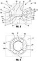
- FIGS. 7A and 7B illustrate upper and lower views of the exemplary insert 310.
- the insert 310 may include multiple ports 316 circumferentially spaced around the insert, for example, to provide for increased flow between the offset passage(s) 38, 39 and the tubular extension 315. While the insert 310 may be machined with the multiple port configuration, the insert 310 (as well as any of the other components described herein) may be manufactured using additive manufacturing (e.g., 3D printing) and/or welded configurations (e.g., an insert formed from a tubular extension welded to a ported base).
- additive manufacturing e.g., 3D printing
- welded configurations e.g., an insert formed from a tubular extension welded to a ported base.
- the web portion 313 of the insert 310 may be thin enough to provide a degree of axial flexing between the outer and inner sealing beads so that differences in the valve cavity recessed surface can be accommodated and the load transfer from outer to inner seal is minimized, for example, similar to the web portion 113 of the insert 110 of FIG. 3 , as described above.
- the web portion 313 is substantially coplanar with the outer bearing surface 318, for example, to provide an enlarged space between the valve cavity recessed surface 34 and the web portion 313 to maximize flow between the offset passages 38, 39.
- the insert may include a web portion that is more centrally positioned between the upper bearing surfaces and the lower annular sealing surfaces, for example, to provide increased flexibility between the outer and inner sealing beads, for example, in embodiments for which flow capacity is less critical or where only one offset passage is provided.
Landscapes
- Engineering & Computer Science (AREA)
- General Engineering & Computer Science (AREA)
- Mechanical Engineering (AREA)
- Valve Housings (AREA)
- Pipe Accessories (AREA)
Applications Claiming Priority (2)
| Application Number | Priority Date | Filing Date | Title |
|---|---|---|---|
| US202063110443P | 2020-11-06 | 2020-11-06 | |
| PCT/US2021/057808 WO2022098688A1 (en) | 2020-11-06 | 2021-11-03 | Valve cavity cap arrangements |
Publications (3)
| Publication Number | Publication Date |
|---|---|
| EP4240998A1 EP4240998A1 (en) | 2023-09-13 |
| EP4240998B1 true EP4240998B1 (en) | 2025-06-18 |
| EP4240998C0 EP4240998C0 (en) | 2025-06-18 |
Family
ID=78806690
Family Applications (1)
| Application Number | Title | Priority Date | Filing Date |
|---|---|---|---|
| EP21815792.3A Active EP4240998B1 (en) | 2020-11-06 | 2021-11-03 | Valve cavity cap arrangements |
Country Status (7)
| Country | Link |
|---|---|
| US (1) | US11796077B2 (https=) |
| EP (1) | EP4240998B1 (https=) |
| JP (1) | JP7629524B2 (https=) |
| KR (1) | KR20230093446A (https=) |
| CN (1) | CN116420042B (https=) |
| TW (1) | TWI899367B (https=) |
| WO (1) | WO2022098688A1 (https=) |
Families Citing this family (2)
| Publication number | Priority date | Publication date | Assignee | Title |
|---|---|---|---|---|
| US12000505B2 (en) * | 2020-04-30 | 2024-06-04 | Emerson Automation Solutions Final Control US LP | Systems and methods for determining failure in a back pressure balanced relief valve |
| KR20250013054A (ko) | 2023-07-18 | 2025-01-31 | 주식회사 엘지에너지솔루션 | 커넥터, 및 이를 포함하는 배터리 모듈 |
Citations (1)
| Publication number | Priority date | Publication date | Assignee | Title |
|---|---|---|---|---|
| US5881997A (en) * | 1997-11-24 | 1999-03-16 | Fujikin Incorporated | Metal diaphragm type valve |
Family Cites Families (60)
| Publication number | Priority date | Publication date | Assignee | Title |
|---|---|---|---|---|
| US2323531A (en) * | 1941-09-08 | 1943-07-06 | Imp Brass Mfg Co | Diaphragm valve |
| US5334864A (en) | 1987-03-26 | 1994-08-02 | Canon Kabushiki Kaisha | Process for selective formation of II-VI group compound film |
| US5335691A (en) | 1992-05-26 | 1994-08-09 | Nupro Company | High pressure diaphragm valve |
| US5314164A (en) | 1992-07-17 | 1994-05-24 | Mks Instruments, Inc. | Pivotal diaphragm, flow control valve |
| JP2739063B2 (ja) * | 1995-04-05 | 1998-04-08 | 高砂電氣工業株式会社 | バルブ |
| DE19638201B4 (de) | 1996-09-19 | 2005-05-04 | Robert Bosch Gmbh | Brennstoffeinspritzventil |
| DE19653832A1 (de) | 1996-12-21 | 1998-06-25 | Bosch Gmbh Robert | Ventil mit kombiniertem Ventilsitzkörper und Spritzlochscheibe |
| JP3941844B2 (ja) | 1997-06-03 | 2007-07-04 | シーケーディ株式会社 | ガス制御バルブ |
| US6000416A (en) * | 1997-06-04 | 1999-12-14 | Furon Company | Compact valve with rolling diaphragm poppet |
| DE19736682A1 (de) | 1997-08-22 | 1999-02-25 | Bosch Gmbh Robert | Brennstoffeinspritzventil |
| US5909747A (en) | 1998-04-03 | 1999-06-08 | American Meter Company | Radial flow diaphragm valve |
| JP3522535B2 (ja) | 1998-05-29 | 2004-04-26 | 忠弘 大見 | 圧力式流量制御装置を備えたガス供給設備 |
| DK1144889T3 (da) * | 1998-12-23 | 2011-05-16 | Goyen Controls Co | Ventil til styring af luftstrøm |
| JP3502561B2 (ja) | 1999-02-22 | 2004-03-02 | Smc株式会社 | レギュレーター |
| DE19946838C1 (de) | 1999-09-30 | 2000-10-19 | Bosch Gmbh Robert | Ventil zum Steuern von Flüssigkeiten |
| KR100426709B1 (ko) | 2000-06-05 | 2004-04-14 | 가부시키가이샤 후지킨 | 오리피스 내장밸브 |
| US6685164B1 (en) * | 2000-09-11 | 2004-02-03 | Hamai Industries Limited | Control valve and diaphragm for use in the control valve |
| CA2370819C (en) | 2001-02-09 | 2005-07-26 | Jennmar Corporation | Cable bolt with mixing delay device |
| US20030042459A1 (en) | 2001-08-29 | 2003-03-06 | Gregoire Roger J. | Unitary diaphragm and seat assembly |
| US8215336B2 (en) * | 2002-04-15 | 2012-07-10 | Jennings Jeffrey D | Fluid balancing relief valve with grooved process surface |
| JP4197627B2 (ja) | 2003-06-02 | 2008-12-17 | シーケーディ株式会社 | ガスレギュレータ |
| JP3861206B2 (ja) | 2003-12-08 | 2006-12-20 | 株式会社フジキン | 流体制御器 |
| JP2005188672A (ja) | 2003-12-26 | 2005-07-14 | Neriki:Kk | バルブ装置 |
| EP1721227A4 (en) | 2004-02-27 | 2010-02-03 | Horiba Stec Co Ltd | THROTTLE BODY |
| DE102004033280A1 (de) | 2004-07-09 | 2006-02-02 | Robert Bosch Gmbh | Einspritzventil zur Kraftstoffeinspritzung |
| JP2006090386A (ja) * | 2004-09-22 | 2006-04-06 | Kitz Sct:Kk | ダイヤフラムバルブ |
| JP4549981B2 (ja) | 2006-01-27 | 2010-09-22 | 株式会社キッツエスシーティー | 流体制御機器 |
| JP4256884B2 (ja) | 2006-06-23 | 2009-04-22 | 東京エレクトロン株式会社 | 気化器への原料液供給ユニット |
| EP2003379A1 (en) | 2007-06-12 | 2008-12-17 | Luxembourg Patent Company S.A. | High pressure diaphragm valve with exchangeable seat assembly |
| US8267375B1 (en) * | 2007-10-01 | 2012-09-18 | Numatics, Incorporated | Cartridge valve and manifold assembly |
| CN201373165Y (zh) * | 2009-01-24 | 2009-12-30 | 厦门市伯奥思卫浴科技有限公司 | 坐便器陶瓷磁力阀芯进水阀 |
| WO2011163210A1 (en) | 2010-06-22 | 2011-12-29 | Swagelok Company | Clamp ring for welded diaphragms |
| DE102010064268A1 (de) | 2010-12-28 | 2012-06-28 | Robert Bosch Gmbh | Einspritzventil |
| DE202011004671U1 (de) * | 2011-03-31 | 2011-06-09 | Bürkert Werke GmbH, 74653 | Membranventil |
| DE102012211665A1 (de) | 2011-08-18 | 2013-02-21 | Robert Bosch Gmbh | Ventil für ein strömendes Fluid |
| US9188989B1 (en) | 2011-08-20 | 2015-11-17 | Daniel T. Mudd | Flow node to deliver process gas using a remote pressure measurement device |
| US9863542B2 (en) | 2013-02-01 | 2018-01-09 | Swagelok Company | Diaphragm valve with welded diaphragm seat carrier |
| JP6141663B2 (ja) | 2013-03-27 | 2017-06-07 | 株式会社堀場エステック | 流体制御弁 |
| EP2792902B1 (en) | 2013-04-16 | 2016-09-07 | Öhlins Racing Ab | Valve arrangement |
| JP6072648B2 (ja) | 2013-08-12 | 2017-02-01 | 株式会社フジキン | ダイヤフラム弁 |
| JP5891536B2 (ja) * | 2013-11-11 | 2016-03-23 | Smc株式会社 | 弁装置 |
| CN103672257B (zh) * | 2013-12-31 | 2015-08-26 | 重庆前卫海洋石油工程设备有限责任公司 | 一种水下快速液压接头 |
| JP6335685B2 (ja) | 2014-06-30 | 2018-05-30 | 株式会社フジキン | ダイヤフラム弁、流体制御装置、半導体製造装置および半導体製造方法 |
| ES2755400T3 (es) * | 2015-04-23 | 2020-04-22 | Swagelok Co | Conjunto de conector de empuje para conexión para un conducto |
| JP6602553B2 (ja) | 2015-04-30 | 2019-11-06 | Ckd株式会社 | ダイアフラム、流体制御装置、及びダイアフラムの製造方法 |
| JP6216738B2 (ja) | 2015-05-26 | 2017-10-18 | Ckd株式会社 | パイロット式電磁弁 |
| US10781892B2 (en) | 2015-07-31 | 2020-09-22 | Borgwarner Inc. | Press-fit check valve for a hydraulic tensioner reservoir with metered backflow |
| WO2018021277A1 (ja) | 2016-07-29 | 2018-02-01 | 株式会社フジキン | オリフィス内蔵弁および圧力式流量制御装置 |
| CN110114601B (zh) | 2016-12-26 | 2020-10-27 | 株式会社富士金 | 压电元件驱动式阀以及流量控制装置 |
| US20180313463A1 (en) * | 2017-04-26 | 2018-11-01 | Robertshaw Controls Company | Pilot operated valve with extended insert |
| US10982633B2 (en) | 2017-07-03 | 2021-04-20 | Continental Automotive Systems, Inc. | Fuel pump solenoid assembly method |
| WO2019047916A1 (zh) | 2017-09-08 | 2019-03-14 | 江苏科维仪表控制工程有限公司 | 密封性优越式手动高温高压疏水球阀 |
| US11231026B2 (en) | 2017-10-31 | 2022-01-25 | Fujikin Incorporated | Valve device |
| US10774938B2 (en) * | 2017-11-09 | 2020-09-15 | Swagelok Company | Diaphragm valve with metal seat |
| US10877495B2 (en) | 2018-03-08 | 2020-12-29 | Emerson Process Management Regulator Technologies, Inc. | Pressure loaded regulator with dual diaphragm and redundant seal |
| US11402029B2 (en) | 2018-04-06 | 2022-08-02 | Fujikin Incorporated | Valve device, fluid control system, fluid control method, semiconductor manufacturing system, and semiconductor manufacturing method |
| KR102499250B1 (ko) | 2018-09-25 | 2023-02-10 | 가부시키가이샤 후지킨 | 밸브 |
| JP2020204369A (ja) | 2019-06-18 | 2020-12-24 | Ckd株式会社 | ダイアフラムバルブの製造方法 |
| JP2021021408A (ja) | 2019-07-25 | 2021-02-18 | 株式会社ノーリツ | 流量調整弁 |
| WO2021101855A1 (en) | 2019-11-18 | 2021-05-27 | Swagelok Company | Arrangements and methods for controlled valve flow rate |
-
2021
- 2021-11-03 WO PCT/US2021/057808 patent/WO2022098688A1/en not_active Ceased
- 2021-11-03 EP EP21815792.3A patent/EP4240998B1/en active Active
- 2021-11-03 JP JP2023526894A patent/JP7629524B2/ja active Active
- 2021-11-03 US US17/518,173 patent/US11796077B2/en active Active
- 2021-11-03 KR KR1020237015625A patent/KR20230093446A/ko active Pending
- 2021-11-03 CN CN202180075052.3A patent/CN116420042B/zh active Active
- 2021-11-05 TW TW110141357A patent/TWI899367B/zh active
Patent Citations (1)
| Publication number | Priority date | Publication date | Assignee | Title |
|---|---|---|---|---|
| US5881997A (en) * | 1997-11-24 | 1999-03-16 | Fujikin Incorporated | Metal diaphragm type valve |
Also Published As
| Publication number | Publication date |
|---|---|
| TW202219410A (zh) | 2022-05-16 |
| CN116420042A (zh) | 2023-07-11 |
| JP2023550601A (ja) | 2023-12-04 |
| US20220146010A1 (en) | 2022-05-12 |
| EP4240998C0 (en) | 2025-06-18 |
| EP4240998A1 (en) | 2023-09-13 |
| KR20230093446A (ko) | 2023-06-27 |
| JP7629524B2 (ja) | 2025-02-13 |
| US11796077B2 (en) | 2023-10-24 |
| TWI899367B (zh) | 2025-10-01 |
| WO2022098688A1 (en) | 2022-05-12 |
| CN116420042B (zh) | 2024-06-21 |
Similar Documents
| Publication | Publication Date | Title |
|---|---|---|
| US10843947B2 (en) | Diaphragm valve with diaphragm seat carrier | |
| EP4240998B1 (en) | Valve cavity cap arrangements | |
| US8408245B2 (en) | Valve actuator with vent | |
| US12203568B2 (en) | Valves with integrated orifice restrictions | |
| US9133942B2 (en) | Valve structure for fluid pressure device | |
| KR102295304B1 (ko) | 밸브장치 | |
| KR102295310B1 (ko) | 밸브장치 | |
| US11879560B2 (en) | Flow-path forming block and fluid control device provided with flow-path forming block | |
| WO2020085300A1 (ja) | バルブ装置およびガス供給システム | |
| WO2020085302A1 (ja) | バルブ装置およびガス供給システム |
Legal Events
| Date | Code | Title | Description |
|---|---|---|---|
| STAA | Information on the status of an ep patent application or granted ep patent |
Free format text: STATUS: UNKNOWN |
|
| STAA | Information on the status of an ep patent application or granted ep patent |
Free format text: STATUS: THE INTERNATIONAL PUBLICATION HAS BEEN MADE |
|
| PUAI | Public reference made under article 153(3) epc to a published international application that has entered the european phase |
Free format text: ORIGINAL CODE: 0009012 |
|
| STAA | Information on the status of an ep patent application or granted ep patent |
Free format text: STATUS: REQUEST FOR EXAMINATION WAS MADE |
|
| 17P | Request for examination filed |
Effective date: 20230404 |
|
| AK | Designated contracting states |
Kind code of ref document: A1 Designated state(s): AL AT BE BG CH CY CZ DE DK EE ES FI FR GB GR HR HU IE IS IT LI LT LU LV MC MK MT NL NO PL PT RO RS SE SI SK SM TR |
|
| DAV | Request for validation of the european patent (deleted) | ||
| DAX | Request for extension of the european patent (deleted) | ||
| GRAP | Despatch of communication of intention to grant a patent |
Free format text: ORIGINAL CODE: EPIDOSNIGR1 |
|
| STAA | Information on the status of an ep patent application or granted ep patent |
Free format text: STATUS: GRANT OF PATENT IS INTENDED |
|
| INTG | Intention to grant announced |
Effective date: 20250407 |
|
| GRAS | Grant fee paid |
Free format text: ORIGINAL CODE: EPIDOSNIGR3 |
|
| GRAA | (expected) grant |
Free format text: ORIGINAL CODE: 0009210 |
|
| STAA | Information on the status of an ep patent application or granted ep patent |
Free format text: STATUS: THE PATENT HAS BEEN GRANTED |
|
| AK | Designated contracting states |
Kind code of ref document: B1 Designated state(s): AL AT BE BG CH CY CZ DE DK EE ES FI FR GB GR HR HU IE IS IT LI LT LU LV MC MK MT NL NO PL PT RO RS SE SI SK SM TR |
|
| REG | Reference to a national code |
Ref country code: GB Ref legal event code: FG4D |
|
| REG | Reference to a national code |
Ref country code: CH Ref legal event code: EP |
|
| REG | Reference to a national code |
Ref country code: DE Ref legal event code: R096 Ref document number: 602021032547 Country of ref document: DE |
|
| REG | Reference to a national code |
Ref country code: CH Ref legal event code: EP |
|
| REG | Reference to a national code |
Ref country code: IE Ref legal event code: FG4D |
|
| U01 | Request for unitary effect filed |
Effective date: 20250618 |
|
| U07 | Unitary effect registered |
Designated state(s): AT BE BG DE DK EE FI FR IT LT LU LV MT NL PT RO SE SI Effective date: 20250625 |
|
| PG25 | Lapsed in a contracting state [announced via postgrant information from national office to epo] |
Ref country code: NO Free format text: LAPSE BECAUSE OF FAILURE TO SUBMIT A TRANSLATION OF THE DESCRIPTION OR TO PAY THE FEE WITHIN THE PRESCRIBED TIME-LIMIT Effective date: 20250918 Ref country code: GR Free format text: LAPSE BECAUSE OF FAILURE TO SUBMIT A TRANSLATION OF THE DESCRIPTION OR TO PAY THE FEE WITHIN THE PRESCRIBED TIME-LIMIT Effective date: 20250919 |
|
| PG25 | Lapsed in a contracting state [announced via postgrant information from national office to epo] |
Ref country code: HR Free format text: LAPSE BECAUSE OF FAILURE TO SUBMIT A TRANSLATION OF THE DESCRIPTION OR TO PAY THE FEE WITHIN THE PRESCRIBED TIME-LIMIT Effective date: 20250618 |
|
| PG25 | Lapsed in a contracting state [announced via postgrant information from national office to epo] |
Ref country code: RS Free format text: LAPSE BECAUSE OF FAILURE TO SUBMIT A TRANSLATION OF THE DESCRIPTION OR TO PAY THE FEE WITHIN THE PRESCRIBED TIME-LIMIT Effective date: 20250918 |
|
| U20 | Renewal fee for the european patent with unitary effect paid |
Year of fee payment: 5 Effective date: 20251126 |
|
| PG25 | Lapsed in a contracting state [announced via postgrant information from national office to epo] |
Ref country code: IS Free format text: LAPSE BECAUSE OF FAILURE TO SUBMIT A TRANSLATION OF THE DESCRIPTION OR TO PAY THE FEE WITHIN THE PRESCRIBED TIME-LIMIT Effective date: 20251018 |
|
| PG25 | Lapsed in a contracting state [announced via postgrant information from national office to epo] |
Ref country code: SM Free format text: LAPSE BECAUSE OF FAILURE TO SUBMIT A TRANSLATION OF THE DESCRIPTION OR TO PAY THE FEE WITHIN THE PRESCRIBED TIME-LIMIT Effective date: 20250618 |
|
| PG25 | Lapsed in a contracting state [announced via postgrant information from national office to epo] |
Ref country code: CZ Free format text: LAPSE BECAUSE OF FAILURE TO SUBMIT A TRANSLATION OF THE DESCRIPTION OR TO PAY THE FEE WITHIN THE PRESCRIBED TIME-LIMIT Effective date: 20250618 |
|
| PG25 | Lapsed in a contracting state [announced via postgrant information from national office to epo] |
Ref country code: PL Free format text: LAPSE BECAUSE OF FAILURE TO SUBMIT A TRANSLATION OF THE DESCRIPTION OR TO PAY THE FEE WITHIN THE PRESCRIBED TIME-LIMIT Effective date: 20250618 |
|
| PG25 | Lapsed in a contracting state [announced via postgrant information from national office to epo] |
Ref country code: SK Free format text: LAPSE BECAUSE OF FAILURE TO SUBMIT A TRANSLATION OF THE DESCRIPTION OR TO PAY THE FEE WITHIN THE PRESCRIBED TIME-LIMIT Effective date: 20250618 |
|
| PG25 | Lapsed in a contracting state [announced via postgrant information from national office to epo] |
Ref country code: ES Free format text: LAPSE BECAUSE OF FAILURE TO SUBMIT A TRANSLATION OF THE DESCRIPTION OR TO PAY THE FEE WITHIN THE PRESCRIBED TIME-LIMIT Effective date: 20250618 |
|
| PLBE | No opposition filed within time limit |
Free format text: ORIGINAL CODE: 0009261 |
|
| STAA | Information on the status of an ep patent application or granted ep patent |
Free format text: STATUS: NO OPPOSITION FILED WITHIN TIME LIMIT |