EP4240932B1 - Möbel und verfahren zur montage einer schiebetür an einem möbelkorpus - Google Patents
Möbel und verfahren zur montage einer schiebetür an einem möbelkorpus Download PDFInfo
- Publication number
- EP4240932B1 EP4240932B1 EP21806232.1A EP21806232A EP4240932B1 EP 4240932 B1 EP4240932 B1 EP 4240932B1 EP 21806232 A EP21806232 A EP 21806232A EP 4240932 B1 EP4240932 B1 EP 4240932B1
- Authority
- EP
- European Patent Office
- Prior art keywords
- guide
- guide part
- spring
- sliding door
- mounting element
- Prior art date
- Legal status (The legal status is an assumption and is not a legal conclusion. Google has not performed a legal analysis and makes no representation as to the accuracy of the status listed.)
- Active
Links
Images


Classifications
-
- E—FIXED CONSTRUCTIONS
- E05—LOCKS; KEYS; WINDOW OR DOOR FITTINGS; SAFES
- E05D—HINGES OR SUSPENSION DEVICES FOR DOORS, WINDOWS OR WINGS
- E05D15/00—Suspension arrangements for wings
- E05D15/06—Suspension arrangements for wings for wings sliding horizontally more or less in their own plane
- E05D15/0621—Details, e.g. suspension or supporting guides
- E05D15/0626—Details, e.g. suspension or supporting guides for wings suspended at the top
- E05D15/0656—Bottom guides
-
- E—FIXED CONSTRUCTIONS
- E05—LOCKS; KEYS; WINDOW OR DOOR FITTINGS; SAFES
- E05D—HINGES OR SUSPENSION DEVICES FOR DOORS, WINDOWS OR WINGS
- E05D15/00—Suspension arrangements for wings
- E05D15/06—Suspension arrangements for wings for wings sliding horizontally more or less in their own plane
- E05D15/0621—Details, e.g. suspension or supporting guides
- E05D15/066—Details, e.g. suspension or supporting guides for wings supported at the bottom
- E05D15/0691—Top guides
-
- E—FIXED CONSTRUCTIONS
- E05—LOCKS; KEYS; WINDOW OR DOOR FITTINGS; SAFES
- E05Y—INDEXING SCHEME ASSOCIATED WITH SUBCLASSES E05D AND E05F, RELATING TO CONSTRUCTION ELEMENTS, ELECTRIC CONTROL, POWER SUPPLY, POWER SIGNAL OR TRANSMISSION, USER INTERFACES, MOUNTING OR COUPLING, DETAILS, ACCESSORIES, AUXILIARY OPERATIONS NOT OTHERWISE PROVIDED FOR, APPLICATION THEREOF
- E05Y2201/00—Constructional elements; Accessories therefor
- E05Y2201/60—Suspension or transmission members; Accessories therefor
- E05Y2201/622—Suspension or transmission members elements
- E05Y2201/708—Sliders
-
- E—FIXED CONSTRUCTIONS
- E05—LOCKS; KEYS; WINDOW OR DOOR FITTINGS; SAFES
- E05Y—INDEXING SCHEME ASSOCIATED WITH SUBCLASSES E05D AND E05F, RELATING TO CONSTRUCTION ELEMENTS, ELECTRIC CONTROL, POWER SUPPLY, POWER SIGNAL OR TRANSMISSION, USER INTERFACES, MOUNTING OR COUPLING, DETAILS, ACCESSORIES, AUXILIARY OPERATIONS NOT OTHERWISE PROVIDED FOR, APPLICATION THEREOF
- E05Y2600/00—Mounting or coupling arrangements for elements provided for in this subclass
- E05Y2600/50—Mounting methods; Positioning
- E05Y2600/502—Clamping
-
- E—FIXED CONSTRUCTIONS
- E05—LOCKS; KEYS; WINDOW OR DOOR FITTINGS; SAFES
- E05Y—INDEXING SCHEME ASSOCIATED WITH SUBCLASSES E05D AND E05F, RELATING TO CONSTRUCTION ELEMENTS, ELECTRIC CONTROL, POWER SUPPLY, POWER SIGNAL OR TRANSMISSION, USER INTERFACES, MOUNTING OR COUPLING, DETAILS, ACCESSORIES, AUXILIARY OPERATIONS NOT OTHERWISE PROVIDED FOR, APPLICATION THEREOF
- E05Y2600/00—Mounting or coupling arrangements for elements provided for in this subclass
- E05Y2600/50—Mounting methods; Positioning
- E05Y2600/52—Toolless
- E05Y2600/53—Snapping
-
- E—FIXED CONSTRUCTIONS
- E05—LOCKS; KEYS; WINDOW OR DOOR FITTINGS; SAFES
- E05Y—INDEXING SCHEME ASSOCIATED WITH SUBCLASSES E05D AND E05F, RELATING TO CONSTRUCTION ELEMENTS, ELECTRIC CONTROL, POWER SUPPLY, POWER SIGNAL OR TRANSMISSION, USER INTERFACES, MOUNTING OR COUPLING, DETAILS, ACCESSORIES, AUXILIARY OPERATIONS NOT OTHERWISE PROVIDED FOR, APPLICATION THEREOF
- E05Y2600/00—Mounting or coupling arrangements for elements provided for in this subclass
- E05Y2600/50—Mounting methods; Positioning
- E05Y2600/56—Positioning, e.g. re-positioning, or pre-mounting
-
- E—FIXED CONSTRUCTIONS
- E05—LOCKS; KEYS; WINDOW OR DOOR FITTINGS; SAFES
- E05Y—INDEXING SCHEME ASSOCIATED WITH SUBCLASSES E05D AND E05F, RELATING TO CONSTRUCTION ELEMENTS, ELECTRIC CONTROL, POWER SUPPLY, POWER SIGNAL OR TRANSMISSION, USER INTERFACES, MOUNTING OR COUPLING, DETAILS, ACCESSORIES, AUXILIARY OPERATIONS NOT OTHERWISE PROVIDED FOR, APPLICATION THEREOF
- E05Y2600/00—Mounting or coupling arrangements for elements provided for in this subclass
- E05Y2600/60—Mounting or coupling members; Accessories therefor
- E05Y2600/626—Plates or brackets
-
- E—FIXED CONSTRUCTIONS
- E05—LOCKS; KEYS; WINDOW OR DOOR FITTINGS; SAFES
- E05Y—INDEXING SCHEME ASSOCIATED WITH SUBCLASSES E05D AND E05F, RELATING TO CONSTRUCTION ELEMENTS, ELECTRIC CONTROL, POWER SUPPLY, POWER SIGNAL OR TRANSMISSION, USER INTERFACES, MOUNTING OR COUPLING, DETAILS, ACCESSORIES, AUXILIARY OPERATIONS NOT OTHERWISE PROVIDED FOR, APPLICATION THEREOF
- E05Y2900/00—Application of doors, windows, wings or fittings thereof
- E05Y2900/20—Application of doors, windows, wings or fittings thereof for furniture, e.g. cabinets
Definitions
- the present invention relates to a piece of furniture with a furniture body on which at least one sliding door is held so as to be movable along a guide rail via at least one running part, and a guide rail fixed to the furniture body along which at least one guide part held on the sliding door is movable, wherein the guide part is held so as to be movable on a mounting element which is fixed to the sliding door, wherein the guide part is prestressed relative to the mounting element via at least one spring element, and a method for mounting a sliding door on a furniture body.
- a piece of furniture with a sliding element which can be hung on a guide rail via running parts and is guided in a lower area via a guide device.
- the guide device comprises a guide rail fixed to the furniture body and a guide part held on a sliding door, which is held on a mounting element so that it can be moved in a vertical direction.
- the guide part can be moved relative to the mounting element in order to compensate for tolerances caused by the alignment or positioning of the guide rail.
- This type of guide has proven itself to be effective, but grinding or rattling noises can occur when the guide part is moved, particularly since the guide part is held on the guide rail with play.
- DE 10 2016 109 716 discloses a guide device for a sliding element, which comprises a guide rail with at least one groove into which a guide element that can be fixed to a sliding element can be inserted.
- the DE 10 2013 100 922 discloses a running part for guiding a furniture fitting along a guide rail, in which a holder is adjustable in order to then run guided in the guide direction.
- EP 2 248 977 discloses a guide fitting for a sliding door with a guide part housing in which a sliding element is slidably mounted, which is pre-tensioned via a spring element.
- a locking tongue is arranged on the sliding element, which can be locked with a locking element of the guide part housing.
- the object of the present invention to create a piece of furniture in which the guidance of the sliding door along the furniture body is improved.
- the sliding door should be easy to mount on the furniture body.
- a guide part is slidably held on a mounting element that is fixed to a sliding door, wherein the guide part is pre-tensioned relative to the mounting element via at least one spring element.
- the guide part is pre-tensioned in the sliding direction towards the guide rail, so that a defined contact surface of the guide part rests on the guide rail.
- the at least one spring element ensures that the guide part cannot rattle, but is moved along the predetermined contact surface along the guide rail.
- the guide part is pre-tensioned in a vertical direction downwards towards the guide rail.
- the pre-tensioning force of the at least one spring element counteracts the weight of the sliding door.
- the guide part comprises at least one rotatably mounted guide roller that can roll along a guide track on the guide rail. This avoids grinding noises that occur with sliding friction.
- the guide roller can roll, for example, along the top of a guide section of the guide rail and is pre-tensioned towards the guide rail by the force of the at least one spring element.
- the guide roller can be profiled in cross-section, for example concave or convex, in order to guide the sliding door in a lateral horizontal direction perpendicular to the guide rail.
- the at least one spring element can be formed integrally with the guide part and/or the mounting element.
- the at least one spring element comprises a flexible spring bar, which can be moved along a curved guide.
- the force applied by the at least one spring element can be varied, for example by at least 20%, depending on the orientation of the curved guide.
- the curved guide can have different gradients along its course in order to be able to adapt the forces depending on requirements and situation. This means that any spring rate for predeterminable work or assembly processes can be easily generated with a single curved guide.
- the spring element preferably comprises two flexible spring bars, each of which can be moved along a curved guide and can be pivoted in opposite directions when moving along the curved guide by moving the guide part relative to the mounting element.
- the spring elements thus ensure centering and avoid or reduce transverse forces when the guide part moves relative to the mounting element.
- the curved guides can be arranged symmetrically relative to a central plane, so that the transverse forces generated by the spring bars essentially compensate for one another perpendicular to the sliding direction and bring about centering.
- a locking receptacle for the flexible spring bar is formed on the at least one curved guide. This facilitates assembly, since the guide part can be locked in a predetermined position on the mounting element via the locking receptacle. From this locking position, the guide part can then be moved in order to be mounted and moved on a guide section of the guide rail.
- the at least one spring bar of the spring element can be formed on the guide part and the at least one curved guide on the mounting element.
- the curved guide is arranged stationary on the sliding door, while the guide part with the at least one spring bar, preferably the two spring bars, can be moved relative to the mounting element. It is of course also possible to do the opposite, to provide the curved guide on the guide part and the at least one spring bar on the mounting element.
- the guide part can be plugged or pushed onto the assembly element.
- the guide part can be pushed on either from above or below, with a guide track preferably being formed on the assembly element for threading the at least one spring element to the curved guide.
- This guide track can be formed, for example, on an outer side of the assembly element, which is accessible in the assembled position on the back of the sliding door. Then, by moving the guide part with the at least one spring bar, preferably two spring bars, along the guide track, the spring bars can be bent until they are transferred to the curved guide by the guide track. This enables tool-free assembly by pushing a guide part onto the assembly element.
- the guide part preferably has a receptacle into which a web of the mounting element is inserted, along which the guide part can be moved.
- the web can thus have corresponding guide surfaces that are used for guidance.
- a flexible spring bar is formed on the mounting element, which prestresses the guide part upwards relative to the guide rail.
- This allows the mounting element to be made compact with the guide part, whereby the mounting element can be mounted identically for a front and a rear sliding door and only the guide part is modified in order to be held movable on a guide section of a guide rail via a guide roller or a sliding element.
- a moment is created as a result of the off-center arrangement of the spring bar and guide roller or sliding element, which generates a force that acts transversely to the vertical direction.
- At least one running part on a sliding door is first hung on a running rail on the furniture body, whereby the running rail is fixed, for example, to a top panel of the furniture body.
- the sliding door can then be pivoted around the running rail, whereby a guide part on the sliding door comes into contact with a guide rail on the furniture body via a run-on slope and is moved against the force of at least one spring element relative to a mounting element fixed to the sliding door.
- the guide part can then be locked onto the guide rail, with the at least one spring element pre-tensioning the guide part towards the guide rail in the locked position.
- the locking of the guide part preferably takes place via a guide roller which is rotatably mounted on the guide part and can roll along a guide track on a guide section of the guide rail.
- the guide part For effective assembly of the guide part, it can be pushed onto the assembly element during assembly and locked in place using the at least one spring element.
- the at least one spring element can thus enable pre-positioning of the guide part during assembly, so that it can then be moved slightly out of the locked position in the pre-assembled position, and then rest against the guide rail with pre-tension in the assembled position.
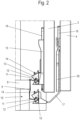
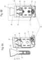
- a piece of furniture 1, in particular a cupboard, comprises a furniture body 2 on which two sliding doors 3 and 4 are arranged to be movable on a front side.
- Each sliding door 3 and 4 comprises one or more running parts 6 in an upper area, in particular with a roller, which can be moved along a running rail 5.
- the running rail 5 is held on an upper floor 7 of the furniture body 2.
- the furniture body 2 can also have just one or more than two sliding doors 3 and 4.
- the furniture body 2 comprises a base 8 to which a guide rail 9 is fixed.
- the guide rail 9 is part of a guide device 10 for guiding the sliding doors 3 and 4 in a lower area.
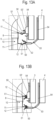
- the guide device 10 is shown in detail.
- the guide rail 9 is fixed to the floor 8 and comprises two protruding webs 11, on each of which a guide section 12 is formed, which in cross section has a thickened section as a bead, rhombus, triangle, cuboid, or with another geometry.
- a guide roller 14 is rotatably mounted on each guide section 12, which can be moved along a guide track on the guide section 12.
- the guide roller 14 is profiled in cross section, in particular concavely or convexly curved, so that movement of the guide roller 14 in the axial direction is prevented.
- the sliding door 3 or 4 can therefore be guided in a direction perpendicular to the direction of travel via the guide roller 14 and a guide part 15 or 25.
- the guide part 15 and the guide part 25 each comprise a holder 13, which has a receptacle into which the thickened guide section 12 can be inserted.
- the holder 13 can be locked to the guide section 12 so that an unintentional release of a sliding door 3 or 4 from the guide rail 9 is prevented.
- the guide part 15 is fixed to the rear of the sliding door 3 via a mounting element 16 and is held so that it can be moved in the vertical direction.
- a mounting element 16 is also fixed to the front sliding door 4, on which a guide part 25 is held so that it can be moved in the vertical direction and is connected to the holder 13 and the guide roller 14 via an adapter 17.
- the adapter 17 can be used to bridge the larger distance between the front sliding door 4 and the guide rail 9, with the function of the guide parts 15 and 25 otherwise being identical.
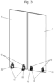
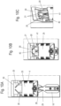
- FIG. 3 the two sliding doors 3 and 4 are shown from a rear side, and it can be seen that two mounting elements 16 are fixed to each sliding door 3 and 4, on each of which a guide part 15 or 25 is slidably held.
- the guide part 25 of the front sliding door 4 is shown in detail.
- the guide part 25 comprises spring elements 20 in the form of two spring bars, which have a contact surface 21 or a driver projection at their end, which can be placed on the mounting element 16.
- the guide part 25 also comprises pockets 22, which can be attached to hooks 23 on the adapter 17, as well as bars 31, which engage in pockets 32 on the adapter 17 in order to act as stops in the vertical direction. This ensures that the guide part 25 is fixed in the correct position on the adapter 17.
- the adapter 17, made from a metal sheet also comprises a central receptacle 26, into which a bar of the mounting element 16 can be inserted.
- the mounting element 16 comprises a web 27 which can be inserted into the receptacle 26 on the adapter 17 of the guide part 25.
- the mounting element 16 is also provided with a curved guide 28 which has a locking receptacle 29.
- the two spring bars of the spring element 20 rest with their contact surface 21 on the curved guide 28, whereby in Figure 6B the locked position is shown, in which the contact surface 21 is arranged on the locking receptacle 29. In this position, the guide part 25 with the holder 13 protrudes downwards over an underside of the sliding door 4.
- the sliding door 3 or 4 is first hung on the top of the sliding door via the running parts 6 on the running rail 5.
- the sliding doors 3 and 4 can then be pivoted around the running rail 5 so that the guide device 10 is brought into engagement, the pivot axis corresponding to the longitudinal direction of the running rail 5.
- the guide rollers 14 on the guide part 15 or 25 are brought into engagement with the guide section 12 of the guide rail 9.
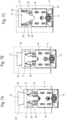
- the guide part 15 or 25 is slightly raised, as shown in Figure 7A is shown.
- the guide roller 14 therefore rests with a pre-tensioning force on the guide section 12 of the guide rail 9 (not shown). If the guide part 25 is now moved along the guide rail 9, it may be necessary to move the guide part 25 along the mounting element 16, for example by slightly inclining the guide rail 9. The guide part 25 is then moved upwards, as shown in Figure 7B is shown. By moving the guide part 25 relative to the mounting element 16, the spring bars of the spring element 20 spread open. If the guide part 25 is to be moved downwards again, the spring bars of the spring element 20 press downwards through contact with the curved guide 28, so that a force is applied to the guide roller 14 during the entire guide movement, regardless of the position of the guide element 25.
- FIG 7C An assembly position is shown in which the sliding door 4 is placed on a floor.
- the guide part 25 is in a locked position in which the spring bars of the spring element 20 rest against the locking receptacle 29. If the sliding door 4 is placed on a floor, it should be prevented that the guide part 25 protruding downwards damages either a floor or the guide part 25 itself.
- the locking is released and the guide part 25 is pushed upwards against the force of the spring bars of the spring element 20 until the Figure 7C shown position is reached, in which the guide part 25 is aligned with a bottom side essentially flush with a bottom side 42 of the sliding door 4.
- the spring bars of the spring element 20 are in a maximum spread position.
- the curve guide 28 is equipped with different inclinations or gradients in its course in order to be able to adjust the spring forces and thus also the spring rate depending on the requirements and situation.
- the spring forces are thus in accordance with the Figures 7A and 7B due to a higher gradient in the lower part of the curve 28 higher than those according to the Figure 7C This is an increase in comfort and safety, as in the working position according to the Figures 7A and 7B higher spring forces are required than in a position according to the Figure 7C , where the sliding door 4 is placed on a floor.
- the spring forces of the Figure 7C shown working position is easily sufficient to move the guide part 25 vertically downwards.
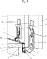
- FIGs 8A and 8B The installation of a guide device 10 of the rear sliding door 3 during pivoting is shown.
- the sliding door 3 with the holder 13 is located in front of the guide section 12, and a run-on slope 18 of the holder 13 rests against the guide section 12.
- the guide part 15 is pressed upwards or moved into a position via the run-on slopes 18 and 33 until the guide section 12 can be inserted into the receptacle on the holder 13, as shown in Figure 8B
- the holder 13 can surround the guide section 12 in a U-shape and lock onto it to prevent the sliding door 3 from accidentally coming loose from the guide rail 9.
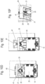
- a modified embodiment of a guide device which comprises a guide part 25 with spring elements 20, which can be mounted on a modified mounting element 16'.
- the mounting element 16' comprises the downwardly projecting web 27, which can be fixed to the rear of the sliding door 3 or 4.
- the mounting element 16' comprises a guide track 40 with a projection 41 between the two curved guides 28, which facilitates threading of the guide part 25 or 15.
- the guide part 25 is designed similarly to the previous embodiment, with a receptacle 26 for inserting the web 27 being designed somewhat wider on the adapter 17'.
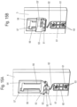
- the assembly of the guide part 25 on the modified mounting element 16' is shown in the Figures 10A to 10F
- the guide part 25 can be pushed from above onto the mounting element 16' fixed to the sliding door 4.
- the guide part 25 is positioned above the mounting element 16' and then moved downwards so that the upper section of the mounting element 16' enters the receptacle 26, the edge of which is arranged between an edge of the mounting element 16' and the back of the sliding door 4.
- the guide part 25 can now be moved downwards, as shown in Figure 10B is shown.
- the spring bars of the spring element 20 with a contact surface 21 enter the guide track 40 on the upper side of the mounting element 16'.
- the contact surfaces 21 on the spring bars are designed as projections that protrude towards the rear of the sliding door 4 and can thus be threaded into the guide track 40.
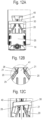
- the locked position of the guide part 25 on the mounting element 16' is in the Figures 11A and 11B shown.
- the spring bars of the spring element 20 were threaded to the curve guide 28 via the guide track 40 and are now locked into the locking receptacle 29.
- the unit can now consisting of sliding door 4, mounting element 16' and guide part 25 are mounted on the guide rail 9, as described above.
- the guide part 25 is moved upwards or brought into position, as shown in the Figures 12A to 12C is shown.
- the spring bars are moved along the curved guide 28 and spread apart, thus ensuring a downward pre-tension of the guide part 25 so that the guide roller 14 rests with pre-tension on the guide section 12 of the guide rail 9.
- the guide track 40 for threading the spring bars ends directly at the locking receptacle 29. It is also possible to provide the end of the guide track 40 at a different position in order to be able to easily mount the guide part 25.
- two spring bars are provided on the guide part 15 or 25, which can be moved along a curved guide 28 on the mounting element 16. It is also possible to provide the spring bars on the mounting element 16 or 16' and the curved guide 28 on the guide part 15 or 25. In addition, the number of spring bars per spring element can be changed, depending on the desired forces for preloading the guide part 15 or 25.
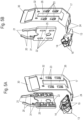
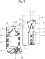
- FIG 13A a modified embodiment of a guide device 10 is shown, in which the guide rail 9 is mounted on a base 8 of a furniture body 2, as already explained above.
- the guide rail 9 comprises two guide sections 12 arranged on webs 11 for guiding at least two sliding doors 3 and 4.
- a sliding guide part 54 is held on each sliding door 3 and 4, on which a sliding element 50 is provided.
- the sliding element 50 is designed with a U-shaped receptacle that can be locked onto a guide section 12 of the guide rail 9.
- inwardly projecting locking webs are formed on the sliding element 50.
- a run-on slope 51 is also formed on the sliding element 50, which is arranged adjacent to a guide section 12 after the sliding doors 3 and 4 have been hung in.
- a further guide slope 52 is also provided on the upper side of the lower sliding element 50, which can optionally be arranged on the sliding element 50.
- the guide parts 54 on the two sliding doors 3 and 4 differ essentially in a connecting part 53 and 53', which are arranged at different heights.
- a connecting part 53 is provided on the guide part 54 of the front sliding door 4, so that the sliding element 50 is arranged adjacent to the lower guide section 12, and a modified connecting part 53' is provided on the guide part 54 of the rear sliding door 3, so that the sliding element 50 is also arranged adjacent to the upper guide section 12.
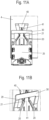
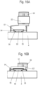
- FIG 14A the guide part 54 is shown in the mounted position on the sliding door 4.
- the guide part 54 is held displaceably by a mounting element 60, which has guide webs 61 on opposite long sides, which are engaged behind by guide webs 56 on the guide part 54.
- the guide webs 56 on the guide part 54 are thus arranged between the guide webs 61 of the mounting element 60 and a rear side of the sliding door 4.
- the mounting element 60 is essentially plate-shaped and is fixed to the sliding door 4 by means of fastening means 63, in particular screws.
- An integrally formed spring bar 62 is provided at an upper end of the mounting element 60, which rests with its free end on a profile 57, in particular a bead or other embossing, on the guide part 54.
- the free end preferably has a thickening.
- FIG 14B the guide part 54 is shown on the rear sliding door 3, which is held displaceably on an identical mounting element 60.
- the guide parts 54 differ essentially only in the position of the sliding elements 50 due to the different design of the connecting parts 53 and 53'.
- the guide parts 54 are moved downwards by the contact of the run-on bevel 51 on the guide section 12, so that the Spring bar 62 is pressed downwards and the guide part 54 is prestressed upwards via the spring bar 62 and the profiling 57 when the sliding element 50 latches onto the guide section 12.
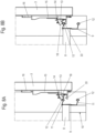
- the contact area where the free end of the spring bar 62 contacts the profile 57 and the imaginary center line of the sliding element 50 are spaced apart in a plane parallel to the sliding direction of the sliding doors 3 and 4.
- this creates a preload directed transversely to this, which causes a slight twisting of the guide part 54 and ultimately a pressing of the guide part 54 against the sliding door 4.
- the effect is supported by an oblique geometric design of the guide bars 56 and 61 and by a beveled surface on the underside of the profile 57, which contacts the free end of the spring bar 62.
- This double preload which acts both in a height direction and in a depth direction directed transversely to this, leads to a noticeable reduction in play, thereby effectively minimizing noise development.
- FIGS 15A and 15B the assembly of a guide part 54 on the already assembled assembly element 60 is shown.
- the assembly elements 60 are of identical construction and are fixed to the sliding door 3 or the sliding door 4 via fastening means 63.
- To assemble a guide part 54 this is placed onto the assembly element 60 from above, with the guide webs 56 on the guide part 54 engaging behind the guide webs 61 on the assembly element 60.
- the guide part 54 is lowered downwards until the spring web 62 rests with one end on the profile 57.
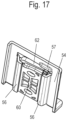
- FIG 17 a rear side of a mounted guide part 54 on the mounting element 60 is shown, with the sliding door being omitted. It can be seen that the profile 57 rests on one end of the spring bar 62 and the guide bars 56 partially engage behind the mounting element 60.
- the mounting element 60 is made of plastic and has a spring bar 62, whereby instead of a one-piece design, a multi-piece design is also possible and moreover, several spring bars 62 can also be provided.
- the guide part 54 can also be made of other materials instead of a metal sheet.
Landscapes
- Engineering & Computer Science (AREA)
- Mechanical Engineering (AREA)
- Support Devices For Sliding Doors (AREA)
Priority Applications (1)
| Application Number | Priority Date | Filing Date | Title |
|---|---|---|---|
| EP24210210.1A EP4477831A3 (de) | 2020-11-09 | 2021-11-05 | Möbel und verfahren zur montage einer schiebetür an einem möbelkorpus |
Applications Claiming Priority (3)
| Application Number | Priority Date | Filing Date | Title |
|---|---|---|---|
| DE102020129498 | 2020-11-09 | ||
| DE102021105984.4A DE102021105984A1 (de) | 2020-11-09 | 2021-03-11 | Möbel und Verfahren zur Montage einer Schiebetür an einem Möbelkorpus |
| PCT/EP2021/080732 WO2022096629A1 (de) | 2020-11-09 | 2021-11-05 | Möbel und verfahren zur montage einer schiebetür an einem möbelkorpus |
Related Child Applications (2)
| Application Number | Title | Priority Date | Filing Date |
|---|---|---|---|
| EP24210210.1A Division EP4477831A3 (de) | 2020-11-09 | 2021-11-05 | Möbel und verfahren zur montage einer schiebetür an einem möbelkorpus |
| EP24210210.1A Division-Into EP4477831A3 (de) | 2020-11-09 | 2021-11-05 | Möbel und verfahren zur montage einer schiebetür an einem möbelkorpus |
Publications (2)
| Publication Number | Publication Date |
|---|---|
| EP4240932A1 EP4240932A1 (de) | 2023-09-13 |
| EP4240932B1 true EP4240932B1 (de) | 2025-01-01 |
Family
ID=81256239
Family Applications (2)
| Application Number | Title | Priority Date | Filing Date |
|---|---|---|---|
| EP21806232.1A Active EP4240932B1 (de) | 2020-11-09 | 2021-11-05 | Möbel und verfahren zur montage einer schiebetür an einem möbelkorpus |
| EP24210210.1A Pending EP4477831A3 (de) | 2020-11-09 | 2021-11-05 | Möbel und verfahren zur montage einer schiebetür an einem möbelkorpus |
Family Applications After (1)
| Application Number | Title | Priority Date | Filing Date |
|---|---|---|---|
| EP24210210.1A Pending EP4477831A3 (de) | 2020-11-09 | 2021-11-05 | Möbel und verfahren zur montage einer schiebetür an einem möbelkorpus |
Country Status (5)
| Country | Link |
|---|---|
| EP (2) | EP4240932B1 (pl) |
| CN (1) | CN116472391A (pl) |
| DE (1) | DE102021105984A1 (pl) |
| PL (1) | PL4240932T3 (pl) |
| WO (1) | WO2022096629A1 (pl) |
Families Citing this family (1)
| Publication number | Priority date | Publication date | Assignee | Title |
|---|---|---|---|---|
| DE102021125767A1 (de) | 2021-10-05 | 2023-04-06 | Hettich-Heinze Gmbh & Co. Kg | Bausatz für einen Schiebetürbeschlag, Möbel und Verfahren zum Umrüsten eines Schiebetürbeschlags |
Family Cites Families (10)
| Publication number | Priority date | Publication date | Assignee | Title |
|---|---|---|---|---|
| DD239824A1 (de) | 1985-08-01 | 1986-10-08 | Luckenwalde Beschlaege Veb | Gleiter fuer schiebetueren |
| JP2549759B2 (ja) * | 1990-10-30 | 1996-10-30 | 松下電工株式会社 | 扉開閉装置 |
| DE202009004790U1 (de) * | 2009-05-06 | 2010-09-23 | Hettich-Heinze Gmbh & Co. Kg | Führungsbeschlag einer Schiebetür |
| KR100988496B1 (ko) * | 2010-03-05 | 2010-10-20 | 신정철 | 가구의 슬라이딩 도어 |
| DE102010037940A1 (de) | 2010-10-04 | 2012-04-05 | Hettich-Heinze Gmbh & Co. Kg | Schiebetür-Rollenführung sowie Anordnung einer Schiebetür-Rollenführung an einem Möbel |
| EP2870311A4 (en) * | 2012-06-25 | 2016-03-16 | Hardoor Top Design & Technology Ltd | APPLICATION MECHANISM FOR INSERTING A ROLL INTO THE LOWER TRACK OF A SLIDING DOOR |
| DE102013100922B4 (de) * | 2013-01-30 | 2025-06-12 | Hettich-Heinze Gmbh & Co. Kg | Laufteil zum Führen eines Möbelteils in einer Führungsrichtung über eine Führungsschiene und Möbelbeschlag |
| DE102016109716A1 (de) * | 2016-05-25 | 2017-11-30 | Hettich-Heinze Gmbh & Co. Kg | Führungseinrichtung für ein Schiebeelement, Möbel und Verfahren zur Montage eines Schiebeelementes |
| DE202016102808U1 (de) * | 2016-05-25 | 2017-08-28 | Hettich-Heinze Gmbh & Co. Kg | Möbel mit einem an einem Laufprofil verfahrbaren Schiebeelement und einer Führungseinrichtung |
| DE202019102727U1 (de) * | 2019-05-15 | 2019-07-12 | Rennerich Gmbh | Führungsvorrichtung für Schiebetüren |
-
2021
- 2021-03-11 DE DE102021105984.4A patent/DE102021105984A1/de active Pending
- 2021-11-05 WO PCT/EP2021/080732 patent/WO2022096629A1/de not_active Ceased
- 2021-11-05 CN CN202180074624.6A patent/CN116472391A/zh active Pending
- 2021-11-05 EP EP21806232.1A patent/EP4240932B1/de active Active
- 2021-11-05 EP EP24210210.1A patent/EP4477831A3/de active Pending
- 2021-11-05 PL PL21806232.1T patent/PL4240932T3/pl unknown
Also Published As
| Publication number | Publication date |
|---|---|
| CN116472391A (zh) | 2023-07-21 |
| EP4477831A3 (de) | 2025-02-12 |
| EP4240932A1 (de) | 2023-09-13 |
| WO2022096629A1 (de) | 2022-05-12 |
| PL4240932T3 (pl) | 2025-04-07 |
| EP4477831A2 (de) | 2024-12-18 |
| DE102021105984A1 (de) | 2022-05-12 |
Similar Documents
| Publication | Publication Date | Title |
|---|---|---|
| EP0956416B1 (de) | Vorrichtung zur befestigung einer verschiebbaren fensterscheibe eines kraftfahrzeugs an der führungsvorrichtung eines fensterhebers | |
| EP1550385A2 (de) | Vorrichtung zur Höhenverstellung einer Schublade | |
| EP3668350B1 (de) | Schubladenausziehführung | |
| AT929U1 (de) | Schubladenführung | |
| WO2019119004A1 (de) | Schubladenausziehführung | |
| DE102019121404A1 (de) | Schiebetürbeschlag, Möbel und Verfahren zur Montage eines Schiebetürbeschlages | |
| EP2625062B1 (de) | Längsverstelleinrichtung für einen kraftfahrzeugsitz | |
| EP3042016B1 (de) | Beschlag für eine schiebetür | |
| DE4301327A1 (en) | Method of fitting a guide rail to sliding drawer - has spring catch fitted to underside of drawer which engages slot in rail and holds it in place | |
| EP4240932B1 (de) | Möbel und verfahren zur montage einer schiebetür an einem möbelkorpus | |
| EP0385167A1 (de) | Seil-Umlenkstück | |
| EP3356629B1 (de) | Beschlag für eine schiebetür und verfahren zur montage einer schiebetür | |
| EP1568838B1 (de) | Führungsschiene für Schiebe- oder Faltschiebetüren | |
| DE19730600A1 (de) | Stulpschienenbeschlag | |
| CH712501A2 (de) | Möbel mit mindestens einem an einem Laufprofil verfahrbaren Schiebeelement und einer Führungseinrichtung. | |
| EP2951374B1 (de) | Laufteil zum führen eines möbelteils in einer führungsrichtung über eine führungsschiene und möbelbeschlag | |
| EP2328439A1 (de) | Möbelauszugsführung | |
| AT510773A1 (de) | Behältnisschiene für einen schubladenbehälter | |
| EP3859105A1 (de) | Schliesseinrichtung | |
| DE20202551U1 (de) | Mitnehmer zur Aufnahme einer mittels eines Kraftfahrzeug-Fensterhebers verstellbaren Fensterscheibe | |
| AT395809B (de) | Ausziehfuehrung fuer schubladen u.dgl. | |
| DE4017706C1 (pl) | ||
| EP0829213A2 (de) | Schubkastenfürhrung | |
| DE10133938A1 (de) | Türfeststeller für Schiebetüren von Kraftfahrzeugen | |
| EP1386796B1 (de) | Gurthöhenversteller für Kraftfahrzeuge |
Legal Events
| Date | Code | Title | Description |
|---|---|---|---|
| STAA | Information on the status of an ep patent application or granted ep patent |
Free format text: STATUS: UNKNOWN |
|
| STAA | Information on the status of an ep patent application or granted ep patent |
Free format text: STATUS: THE INTERNATIONAL PUBLICATION HAS BEEN MADE |
|
| PUAI | Public reference made under article 153(3) epc to a published international application that has entered the european phase |
Free format text: ORIGINAL CODE: 0009012 |
|
| STAA | Information on the status of an ep patent application or granted ep patent |
Free format text: STATUS: REQUEST FOR EXAMINATION WAS MADE |
|
| 17P | Request for examination filed |
Effective date: 20230413 |
|
| AK | Designated contracting states |
Kind code of ref document: A1 Designated state(s): AL AT BE BG CH CY CZ DE DK EE ES FI FR GB GR HR HU IE IS IT LI LT LU LV MC MK MT NL NO PL PT RO RS SE SI SK SM TR |
|
| DAV | Request for validation of the european patent (deleted) | ||
| DAX | Request for extension of the european patent (deleted) | ||
| STAA | Information on the status of an ep patent application or granted ep patent |
Free format text: STATUS: EXAMINATION IS IN PROGRESS |
|
| 17Q | First examination report despatched |
Effective date: 20240404 |
|
| GRAP | Despatch of communication of intention to grant a patent |
Free format text: ORIGINAL CODE: EPIDOSNIGR1 |
|
| STAA | Information on the status of an ep patent application or granted ep patent |
Free format text: STATUS: GRANT OF PATENT IS INTENDED |
|
| INTG | Intention to grant announced |
Effective date: 20240905 |
|
| GRAS | Grant fee paid |
Free format text: ORIGINAL CODE: EPIDOSNIGR3 |
|
| GRAA | (expected) grant |
Free format text: ORIGINAL CODE: 0009210 |
|
| STAA | Information on the status of an ep patent application or granted ep patent |
Free format text: STATUS: THE PATENT HAS BEEN GRANTED |
|
| P01 | Opt-out of the competence of the unified patent court (upc) registered |
Free format text: CASE NUMBER: APP_60172/2024 Effective date: 20241107 |
|
| AK | Designated contracting states |
Kind code of ref document: B1 Designated state(s): AL AT BE BG CH CY CZ DE DK EE ES FI FR GB GR HR HU IE IS IT LI LT LU LV MC MK MT NL NO PL PT RO RS SE SI SK SM TR |
|
| REG | Reference to a national code |
Ref country code: GB Ref legal event code: FG4D Free format text: NOT ENGLISH |
|
| REG | Reference to a national code |
Ref country code: CH Ref legal event code: EP |
|
| REG | Reference to a national code |
Ref country code: DE Ref legal event code: R096 Ref document number: 502021006299 Country of ref document: DE |
|
| REG | Reference to a national code |
Ref country code: IE Ref legal event code: FG4D Free format text: LANGUAGE OF EP DOCUMENT: GERMAN |
|
| REG | Reference to a national code |
Ref country code: LT Ref legal event code: MG9D |
|
| REG | Reference to a national code |
Ref country code: NL Ref legal event code: MP Effective date: 20250101 |
|
| PG25 | Lapsed in a contracting state [announced via postgrant information from national office to epo] |
Ref country code: NL Free format text: LAPSE BECAUSE OF FAILURE TO SUBMIT A TRANSLATION OF THE DESCRIPTION OR TO PAY THE FEE WITHIN THE PRESCRIBED TIME-LIMIT Effective date: 20250101 |
|
| PG25 | Lapsed in a contracting state [announced via postgrant information from national office to epo] |
Ref country code: FI Free format text: LAPSE BECAUSE OF FAILURE TO SUBMIT A TRANSLATION OF THE DESCRIPTION OR TO PAY THE FEE WITHIN THE PRESCRIBED TIME-LIMIT Effective date: 20250101 |
|
| PG25 | Lapsed in a contracting state [announced via postgrant information from national office to epo] |
Ref country code: ES Free format text: LAPSE BECAUSE OF FAILURE TO SUBMIT A TRANSLATION OF THE DESCRIPTION OR TO PAY THE FEE WITHIN THE PRESCRIBED TIME-LIMIT Effective date: 20250101 |
|
| PG25 | Lapsed in a contracting state [announced via postgrant information from national office to epo] |
Ref country code: NO Free format text: LAPSE BECAUSE OF FAILURE TO SUBMIT A TRANSLATION OF THE DESCRIPTION OR TO PAY THE FEE WITHIN THE PRESCRIBED TIME-LIMIT Effective date: 20250401 Ref country code: IS Free format text: LAPSE BECAUSE OF FAILURE TO SUBMIT A TRANSLATION OF THE DESCRIPTION OR TO PAY THE FEE WITHIN THE PRESCRIBED TIME-LIMIT Effective date: 20250501 |
|
| PG25 | Lapsed in a contracting state [announced via postgrant information from national office to epo] |
Ref country code: HR Free format text: LAPSE BECAUSE OF FAILURE TO SUBMIT A TRANSLATION OF THE DESCRIPTION OR TO PAY THE FEE WITHIN THE PRESCRIBED TIME-LIMIT Effective date: 20250101 |
|
| PG25 | Lapsed in a contracting state [announced via postgrant information from national office to epo] |
Ref country code: PT Free format text: LAPSE BECAUSE OF FAILURE TO SUBMIT A TRANSLATION OF THE DESCRIPTION OR TO PAY THE FEE WITHIN THE PRESCRIBED TIME-LIMIT Effective date: 20250502 Ref country code: LV Free format text: LAPSE BECAUSE OF FAILURE TO SUBMIT A TRANSLATION OF THE DESCRIPTION OR TO PAY THE FEE WITHIN THE PRESCRIBED TIME-LIMIT Effective date: 20250101 |
|
| PG25 | Lapsed in a contracting state [announced via postgrant information from national office to epo] |
Ref country code: BG Free format text: LAPSE BECAUSE OF FAILURE TO SUBMIT A TRANSLATION OF THE DESCRIPTION OR TO PAY THE FEE WITHIN THE PRESCRIBED TIME-LIMIT Effective date: 20250101 Ref country code: GR Free format text: LAPSE BECAUSE OF FAILURE TO SUBMIT A TRANSLATION OF THE DESCRIPTION OR TO PAY THE FEE WITHIN THE PRESCRIBED TIME-LIMIT Effective date: 20250402 |
|
| PG25 | Lapsed in a contracting state [announced via postgrant information from national office to epo] |
Ref country code: CZ Free format text: LAPSE BECAUSE OF FAILURE TO SUBMIT A TRANSLATION OF THE DESCRIPTION OR TO PAY THE FEE WITHIN THE PRESCRIBED TIME-LIMIT Effective date: 20250101 |
|
| PG25 | Lapsed in a contracting state [announced via postgrant information from national office to epo] |
Ref country code: SE Free format text: LAPSE BECAUSE OF FAILURE TO SUBMIT A TRANSLATION OF THE DESCRIPTION OR TO PAY THE FEE WITHIN THE PRESCRIBED TIME-LIMIT Effective date: 20250101 |
|
| REG | Reference to a national code |
Ref country code: DE Ref legal event code: R097 Ref document number: 502021006299 Country of ref document: DE |
|
| PG25 | Lapsed in a contracting state [announced via postgrant information from national office to epo] |
Ref country code: SM Free format text: LAPSE BECAUSE OF FAILURE TO SUBMIT A TRANSLATION OF THE DESCRIPTION OR TO PAY THE FEE WITHIN THE PRESCRIBED TIME-LIMIT Effective date: 20250101 |
|
| PG25 | Lapsed in a contracting state [announced via postgrant information from national office to epo] |
Ref country code: DK Free format text: LAPSE BECAUSE OF FAILURE TO SUBMIT A TRANSLATION OF THE DESCRIPTION OR TO PAY THE FEE WITHIN THE PRESCRIBED TIME-LIMIT Effective date: 20250101 |
|
| PG25 | Lapsed in a contracting state [announced via postgrant information from national office to epo] |
Ref country code: EE Free format text: LAPSE BECAUSE OF FAILURE TO SUBMIT A TRANSLATION OF THE DESCRIPTION OR TO PAY THE FEE WITHIN THE PRESCRIBED TIME-LIMIT Effective date: 20250101 |
|
| PG25 | Lapsed in a contracting state [announced via postgrant information from national office to epo] |
Ref country code: RO Free format text: LAPSE BECAUSE OF FAILURE TO SUBMIT A TRANSLATION OF THE DESCRIPTION OR TO PAY THE FEE WITHIN THE PRESCRIBED TIME-LIMIT Effective date: 20250101 |
|
| PG25 | Lapsed in a contracting state [announced via postgrant information from national office to epo] |
Ref country code: SK Free format text: LAPSE BECAUSE OF FAILURE TO SUBMIT A TRANSLATION OF THE DESCRIPTION OR TO PAY THE FEE WITHIN THE PRESCRIBED TIME-LIMIT Effective date: 20250101 |
|
| PLBE | No opposition filed within time limit |
Free format text: ORIGINAL CODE: 0009261 |
|
| STAA | Information on the status of an ep patent application or granted ep patent |
Free format text: STATUS: NO OPPOSITION FILED WITHIN TIME LIMIT |
|
| REG | Reference to a national code |
Ref country code: CH Ref legal event code: L10 Free format text: ST27 STATUS EVENT CODE: U-0-0-L10-L00 (AS PROVIDED BY THE NATIONAL OFFICE) Effective date: 20251112 |
|
| REG | Reference to a national code |
Ref country code: CH Ref legal event code: U11 Free format text: ST27 STATUS EVENT CODE: U-0-0-U10-U11 (AS PROVIDED BY THE NATIONAL OFFICE) Effective date: 20251201 |