EP4238914A1 - Unbemanntes liefersystem und unbemanntes lieferverfahren - Google Patents
Unbemanntes liefersystem und unbemanntes lieferverfahren Download PDFInfo
- Publication number
- EP4238914A1 EP4238914A1 EP21886026.0A EP21886026A EP4238914A1 EP 4238914 A1 EP4238914 A1 EP 4238914A1 EP 21886026 A EP21886026 A EP 21886026A EP 4238914 A1 EP4238914 A1 EP 4238914A1
- Authority
- EP
- European Patent Office
- Prior art keywords
- robot
- self
- package
- propelled
- operator
- Prior art date
- Legal status (The legal status is an assumption and is not a legal conclusion. Google has not performed a legal analysis and makes no representation as to the accuracy of the status listed.)
- Pending
Links
Images


Classifications
-
- B—PERFORMING OPERATIONS; TRANSPORTING
- B25—HAND TOOLS; PORTABLE POWER-DRIVEN TOOLS; MANIPULATORS
- B25J—MANIPULATORS; CHAMBERS PROVIDED WITH MANIPULATION DEVICES
- B25J9/00—Program-controlled manipulators
- B25J9/16—Program controls
- B25J9/1694—Program controls characterised by use of sensors other than normal servo-feedback from position, speed or acceleration sensors, perception control, multi-sensor controlled systems, sensor fusion
- B25J9/1697—Vision controlled systems
-
- B—PERFORMING OPERATIONS; TRANSPORTING
- B25—HAND TOOLS; PORTABLE POWER-DRIVEN TOOLS; MANIPULATORS
- B25J—MANIPULATORS; CHAMBERS PROVIDED WITH MANIPULATION DEVICES
- B25J11/00—Manipulators not otherwise provided for
- B25J11/008—Manipulators for service tasks
-
- B—PERFORMING OPERATIONS; TRANSPORTING
- B25—HAND TOOLS; PORTABLE POWER-DRIVEN TOOLS; MANIPULATORS
- B25J—MANIPULATORS; CHAMBERS PROVIDED WITH MANIPULATION DEVICES
- B25J13/00—Controls for manipulators
- B25J13/003—Controls for manipulators by means of an audio-responsive input
-
- B—PERFORMING OPERATIONS; TRANSPORTING
- B25—HAND TOOLS; PORTABLE POWER-DRIVEN TOOLS; MANIPULATORS
- B25J—MANIPULATORS; CHAMBERS PROVIDED WITH MANIPULATION DEVICES
- B25J13/00—Controls for manipulators
- B25J13/02—Hand grip control means
-
- B—PERFORMING OPERATIONS; TRANSPORTING
- B25—HAND TOOLS; PORTABLE POWER-DRIVEN TOOLS; MANIPULATORS
- B25J—MANIPULATORS; CHAMBERS PROVIDED WITH MANIPULATION DEVICES
- B25J13/00—Controls for manipulators
- B25J13/06—Control stands, e.g. consoles, switchboards
- B25J13/065—Control stands, e.g. consoles, switchboards comprising joy-sticks
-
- B—PERFORMING OPERATIONS; TRANSPORTING
- B25—HAND TOOLS; PORTABLE POWER-DRIVEN TOOLS; MANIPULATORS
- B25J—MANIPULATORS; CHAMBERS PROVIDED WITH MANIPULATION DEVICES
- B25J13/00—Controls for manipulators
- B25J13/08—Controls for manipulators by means of sensing devices, e.g. viewing or touching devices
- B25J13/088—Controls for manipulators by means of sensing devices, e.g. viewing or touching devices with position, velocity or acceleration sensors
- B25J13/089—Determining the position of the robot with reference to its environment
-
- B—PERFORMING OPERATIONS; TRANSPORTING
- B25—HAND TOOLS; PORTABLE POWER-DRIVEN TOOLS; MANIPULATORS
- B25J—MANIPULATORS; CHAMBERS PROVIDED WITH MANIPULATION DEVICES
- B25J19/00—Accessories fitted to manipulators, e.g. for monitoring, for viewing; Safety devices combined with or specially adapted for use in connection with manipulators
- B25J19/02—Sensing devices
- B25J19/021—Optical sensing devices
- B25J19/023—Optical sensing devices including video camera means
-
- B—PERFORMING OPERATIONS; TRANSPORTING
- B25—HAND TOOLS; PORTABLE POWER-DRIVEN TOOLS; MANIPULATORS
- B25J—MANIPULATORS; CHAMBERS PROVIDED WITH MANIPULATION DEVICES
- B25J19/00—Accessories fitted to manipulators, e.g. for monitoring, for viewing; Safety devices combined with or specially adapted for use in connection with manipulators
- B25J19/02—Sensing devices
- B25J19/026—Acoustical sensing devices
-
- B—PERFORMING OPERATIONS; TRANSPORTING
- B25—HAND TOOLS; PORTABLE POWER-DRIVEN TOOLS; MANIPULATORS
- B25J—MANIPULATORS; CHAMBERS PROVIDED WITH MANIPULATION DEVICES
- B25J5/00—Manipulators mounted on wheels or on carriages
- B25J5/007—Manipulators mounted on wheels or on carriages mounted on wheels
-
- B—PERFORMING OPERATIONS; TRANSPORTING
- B25—HAND TOOLS; PORTABLE POWER-DRIVEN TOOLS; MANIPULATORS
- B25J—MANIPULATORS; CHAMBERS PROVIDED WITH MANIPULATION DEVICES
- B25J9/00—Program-controlled manipulators
- B25J9/16—Program controls
- B25J9/1656—Program controls characterised by programming, planning systems for manipulators
- B25J9/1664—Program controls characterised by programming, planning systems for manipulators characterised by motion, path, trajectory planning
-
- B—PERFORMING OPERATIONS; TRANSPORTING
- B25—HAND TOOLS; PORTABLE POWER-DRIVEN TOOLS; MANIPULATORS
- B25J—MANIPULATORS; CHAMBERS PROVIDED WITH MANIPULATION DEVICES
- B25J9/00—Program-controlled manipulators
- B25J9/16—Program controls
- B25J9/1679—Program controls characterised by the tasks executed
- B25J9/1682—Dual arm manipulator; Coordination of several manipulators
-
- B—PERFORMING OPERATIONS; TRANSPORTING
- B25—HAND TOOLS; PORTABLE POWER-DRIVEN TOOLS; MANIPULATORS
- B25J—MANIPULATORS; CHAMBERS PROVIDED WITH MANIPULATION DEVICES
- B25J9/00—Program-controlled manipulators
- B25J9/16—Program controls
- B25J9/1679—Program controls characterised by the tasks executed
- B25J9/1689—Teleoperation
-
- B—PERFORMING OPERATIONS; TRANSPORTING
- B64—AIRCRAFT; AVIATION; COSMONAUTICS
- B64C—AEROPLANES; HELICOPTERS
- B64C39/00—Aircraft not otherwise provided for
- B64C39/02—Aircraft not otherwise provided for characterised by special use
- B64C39/024—Aircraft not otherwise provided for characterised by special use of the remote controlled vehicle type, i.e. RPV
-
- B—PERFORMING OPERATIONS; TRANSPORTING
- B64—AIRCRAFT; AVIATION; COSMONAUTICS
- B64U—UNMANNED AERIAL VEHICLES [UAV]; EQUIPMENT THEREFOR
- B64U10/00—Type of UAV
- B64U10/10—Rotorcrafts
- B64U10/17—Helicopters
-
- B—PERFORMING OPERATIONS; TRANSPORTING
- B64—AIRCRAFT; AVIATION; COSMONAUTICS
- B64U—UNMANNED AERIAL VEHICLES [UAV]; EQUIPMENT THEREFOR
- B64U10/00—Type of UAV
- B64U10/20—Vertical take-off and landing [VTOL] aircraft
-
- G—PHYSICS
- G05—CONTROLLING; REGULATING
- G05D—SYSTEMS FOR CONTROLLING OR REGULATING NON-ELECTRIC VARIABLES
- G05D1/00—Control of position, course, altitude or attitude of land, water, air or space vehicles, e.g. using automatic pilots
- G05D1/0011—Control of position, course, altitude or attitude of land, water, air or space vehicles, e.g. using automatic pilots associated with a remote control arrangement
- G05D1/0038—Control of position, course, altitude or attitude of land, water, air or space vehicles, e.g. using automatic pilots associated with a remote control arrangement by providing the operator with simple or augmented images from one or more cameras located onboard the vehicle, e.g. tele-operation
-
- G—PHYSICS
- G06—COMPUTING OR CALCULATING; COUNTING
- G06Q—INFORMATION AND COMMUNICATION TECHNOLOGY [ICT] SPECIALLY ADAPTED FOR ADMINISTRATIVE, COMMERCIAL, FINANCIAL, MANAGERIAL OR SUPERVISORY PURPOSES; SYSTEMS OR METHODS SPECIALLY ADAPTED FOR ADMINISTRATIVE, COMMERCIAL, FINANCIAL, MANAGERIAL OR SUPERVISORY PURPOSES, NOT OTHERWISE PROVIDED FOR
- G06Q10/00—Administration; Management
- G06Q10/08—Logistics, e.g. warehousing, loading or distribution; Inventory or stock management
- G06Q10/083—Shipping
-
- G—PHYSICS
- G06—COMPUTING OR CALCULATING; COUNTING
- G06V—IMAGE OR VIDEO RECOGNITION OR UNDERSTANDING
- G06V40/00—Recognition of biometric, human-related or animal-related patterns in image or video data
- G06V40/10—Human or animal bodies, e.g. vehicle occupants or pedestrians; Body parts, e.g. hands
- G06V40/16—Human faces, e.g. facial parts, sketches or expressions
- G06V40/172—Classification, e.g. identification
-
- G—PHYSICS
- G07—CHECKING-DEVICES
- G07C—TIME OR ATTENDANCE REGISTERS; REGISTERING OR INDICATING THE WORKING OF MACHINES; GENERATING RANDOM NUMBERS; VOTING OR LOTTERY APPARATUS; ARRANGEMENTS, SYSTEMS OR APPARATUS FOR CHECKING NOT PROVIDED FOR ELSEWHERE
- G07C9/00—Individual registration on entry or exit
- G07C9/00174—Electronically operated locks; Circuits therefor; Nonmechanical keys therefor, e.g. passive or active electrical keys or other data carriers without mechanical keys
- G07C9/00896—Electronically operated locks; Circuits therefor; Nonmechanical keys therefor, e.g. passive or active electrical keys or other data carriers without mechanical keys specially adapted for particular uses
-
- B—PERFORMING OPERATIONS; TRANSPORTING
- B64—AIRCRAFT; AVIATION; COSMONAUTICS
- B64U—UNMANNED AERIAL VEHICLES [UAV]; EQUIPMENT THEREFOR
- B64U2101/00—UAVs specially adapted for particular uses or applications
- B64U2101/20—UAVs specially adapted for particular uses or applications for use as communications relays, e.g. high-altitude platforms
-
- B—PERFORMING OPERATIONS; TRANSPORTING
- B64—AIRCRAFT; AVIATION; COSMONAUTICS
- B64U—UNMANNED AERIAL VEHICLES [UAV]; EQUIPMENT THEREFOR
- B64U2101/00—UAVs specially adapted for particular uses or applications
- B64U2101/60—UAVs specially adapted for particular uses or applications for transporting passengers; for transporting goods other than weapons
- B64U2101/64—UAVs specially adapted for particular uses or applications for transporting passengers; for transporting goods other than weapons for parcel delivery or retrieval
-
- B—PERFORMING OPERATIONS; TRANSPORTING
- B64—AIRCRAFT; AVIATION; COSMONAUTICS
- B64U—UNMANNED AERIAL VEHICLES [UAV]; EQUIPMENT THEREFOR
- B64U2101/00—UAVs specially adapted for particular uses or applications
- B64U2101/60—UAVs specially adapted for particular uses or applications for transporting passengers; for transporting goods other than weapons
- B64U2101/67—UAVs specially adapted for particular uses or applications for transporting passengers; for transporting goods other than weapons the UAVs comprising tethers for lowering the goods
-
- B—PERFORMING OPERATIONS; TRANSPORTING
- B64—AIRCRAFT; AVIATION; COSMONAUTICS
- B64U—UNMANNED AERIAL VEHICLES [UAV]; EQUIPMENT THEREFOR
- B64U2201/00—UAVs characterised by their flight controls
- B64U2201/10—UAVs characterised by their flight controls autonomous, i.e. by navigating independently from ground or air stations, e.g. by using inertial navigation systems [INS]
-
- B—PERFORMING OPERATIONS; TRANSPORTING
- B64—AIRCRAFT; AVIATION; COSMONAUTICS
- B64U—UNMANNED AERIAL VEHICLES [UAV]; EQUIPMENT THEREFOR
- B64U2201/00—UAVs characterised by their flight controls
- B64U2201/20—Remote controls
-
- G—PHYSICS
- G07—CHECKING-DEVICES
- G07C—TIME OR ATTENDANCE REGISTERS; REGISTERING OR INDICATING THE WORKING OF MACHINES; GENERATING RANDOM NUMBERS; VOTING OR LOTTERY APPARATUS; ARRANGEMENTS, SYSTEMS OR APPARATUS FOR CHECKING NOT PROVIDED FOR ELSEWHERE
- G07C9/00—Individual registration on entry or exit
- G07C9/30—Individual registration on entry or exit not involving the use of a pass
- G07C9/32—Individual registration on entry or exit not involving the use of a pass in combination with an identity check
- G07C9/37—Individual registration on entry or exit not involving the use of a pass in combination with an identity check using biometric data, e.g. fingerprints, iris scans or voice recognition
Definitions
- the present disclosure relates to an unmanned delivery system and an unmanned delivery method.
- a delivery system disclosed in Patent Document 1 transports a package (load) to near a destination by using a vehicle, and then transports the package from there to the destination by using a drone.
- the present disclosure is made to solve the above problem, and one purpose thereof is to provide a delivery system and a delivery method capable of smoothly delivering a package to an addressee.
- an unmanned delivery system includes a self-propelled robot, an unmanned aerial vehicle which transports a package to an intermediate location on the way of delivering the package, a robot interface which remotely operates the self-propelled robot, and a robot controller which controls the self-propelled robot so that the self-propelled robot delivers to a receiver's address the package which is unloaded at the intermediate location, selectively by one of an autonomous operation and a remote operation in which the self-propelled robot is operated in accordance with manipulation of the robot interface.
- an unmanned delivery system includes a self-propelled robot, an unmanned aerial vehicle which transports a package and the self-propelled robot to an intermediate location on the way of delivering the package, a robot interface which remotely operates the self-propelled robot, and a robot controller which controls the self-propelled robot so that the self-propelled robot delivers to a receiver's address the package which is unloaded at the intermediate location, selectively by one of an autonomous operation and a remote operation in which the self-propelled robot is operated in accordance with manipulation of the robot interface.
- an unmanned delivery method includes transporting, by an unmanned aerial vehicle, a package to an intermediate location on the way of delivering the package, remotely operating the self-propelled robot by the robot interface, and delivering to a receiver's address, by the self-propelled robot, the package which is unloaded at the intermediate location, selectively by one of an autonomous operation and a remote operation in which the self-propelled robot is operated in accordance with manipulation of the robot interface.
- an unmanned delivery method includes transporting, by an unmanned aerial vehicle, a package and a self-propelled robot to an intermediate location on the way of delivering the package, remotely operating the self-propelled robot by a robot interface, and delivering to a receiver's address, by the self-propelled robot, the package which is unloaded at the intermediate location, selectively by one of an autonomous operation and a remote operation in which the self-propelled robot is operated in accordance with manipulation of the robot interface.
- the present disclosure has an effect of providing a delivery system and a delivery method capable of smoothly delivering a package to the addressee.
- Fig. 1 is a schematic diagram illustrating one example of an outline configuration of an unmanned delivery system 100 according to Embodiment 1 of the present disclosure.
- the unmanned delivery system 100 of Embodiment 1 includes an unmanned aerial vehicle 1, a self-propelled robot 2, and an operating unit 3.
- the unmanned aerial vehicle is referred to as the "drone.”
- the unmanned delivery system 100 is configured so that the drone 1 transports a package to an intermediate location on the way of the delivery route from a logistics base 5 to the receiver's address 4, and the self-propelled robot 2 delivers to the receiver's address 4 the package unloaded at the intermediate location, selectively by one of the autonomous operation and the remote operation in which the self-propelled robot 2 is operated in accordance with the manipulation of the robot interface.
- the "self-propelled robot” may simply be referred to as the "robot” for simplification.
- the intermediate location along the delivery route means a location on the way of delivering the package. Below, these components will be described in detail.
- the drone 1 is not limited as long as it is capable of transporting the package to be delivered and the self-propelled robot 2.
- the drone 1 may be an airplane or a helicopter.
- the airplane may include, in addition to those which perform the normal takeoff and landing by sliding, a VTOL aircraft (Vertical Take-Off and Landing aircraft).
- the drone 1 is comprised of the VTOL aircraft.
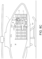
- a storage 16 is formed inside the drone 1, as illustrated in Fig. 8C .
- a load rack 17 is disposed inside the storage 16 so that it surrounds a center space.
- the storage 16 is configured so that the self-propelled robot 2 is stored in this center space and the self-propelled robot 2 can take out and in (pick up and store) the package from/to the load rack 17.
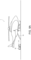
- a cargo door 13 which opens and closes by being rotated in the front-and-rear direction using a lower end part as a fulcrum, is disposed on a side wall of a rear part of the drone 1.
- An inner surface of the cargo door 13 is formed to be flat, and the cargo door 13 becomes a carrying-in-out path for a package G when the cargo door 13 opens and a tip end thereof touches the ground.
- the drone 1 includes a hoist 11.
- the hoist 11 includes a winch.
- a hoist door 15 which opens and closes to the left and right downwardly is disposed on a bottom wall of the drone 1, and this hoist door 15 opens when an object is lifted and lowered by the winch 11.
- a drone controller 101 is disposed in the drone 1.
- the drone controller 101 includes a processor Pr3 and a memory Me3.
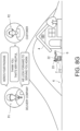
- Fig. 2 is a perspective view illustrating one example of a detailed configuration of the operating unit 3 of Fig. 1 .
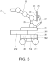
- Fig. 3 is a side view illustrating one example of a configuration of the self-propelled robot 2 of Fig. 1 .
- the operating unit 3 is disposed in a control room 39.
- the disposed location of the operating unit 3 is not limited in particular.
- the operating unit 3 includes a robot interface 31 for manipulating the self-propelled robot 2, a drone interface 32 for manipulating the drone 1, an operator's display 33, an operator's microphone 34, an operator's speaker 35, and an operator's camera 36.
- the robot interface 31 includes a traveller interface module 31A for manipulating a traveller 21 of the self-propelled robot 2, and an arm interface module 31B for manipulating a robotic arm 22 of the self-propelled robot 2.
- the traveller 21 may be a cart or a carrier.
- This arm interface module 31B includes an operating unit for manipulating a display robotic arm 27 for supporting a customer's display 23.
- the robot interface 31 may include various kinds of interface modules. Here, it includes a joystick, for example.
- the robot interface 31 is disposed on a desk 37.
- the drone interface 32 includes various kinds of control levers for controlling the airplane, for example.
- the drone interface 32 includes a joystick-type control lever.
- the drone interface 32 includes various kinds of operating units for controlling the drone 1.
- the drone interface 32 is disposed on the desk 37.
- the operator's display 33 includes a liquid crystal display, for example.
- An image including information needed to be presented to an operator P1 is displayed on the operator's display 33.
- Such an image includes an image captured by a field-of-view camera 26 of the self-propelled robot 2, a field-of-view image captured by a field-of-view camera (not illustrated) of the drone 1, and information, such as a position, a speed, and a fuel amount, which is required for controlling or manipulating the drone 1, as well as a navigation image, etc.
- the operator's display 33 is disposed on the desk 37.
- the operator's speaker 35 outputs audio information necessary for the operator P1. Although the operator's speaker 35 is herein included in a headphone, it may be configured in other forms.
- the operator's microphone 34 acquires voice of the operator P1. Although the operator's microphone 34 is herein included in the headphone or headset 35, it may be configured in other forms.
- the operator's camera 36 images the operator P1. Although the operator's camera 36 is herein included in the operator's display 33, it may be disposed at other locations.
- An operating unit controller 301 is disposed at the desk 37.
- the operating unit controller 301 includes a processor Pr1 and a memory Me1.
- the operator P1 when flying the drone 1, the operator P1 operates the drone interface 32 with the right hand to control the drone 1, and when operating the self-propelled robot 2, the operator P1 operates the traveller interface module 31A and the arm interface module 31B with the left and right hands, respectively, to control the self-propelled robot 2.
- the operator P1 is a package delivery company, for example.
- the delivery company may be a door-to-door delivery person in charge, for example.
- the operator P1 may not be the door-to-door delivery person in charge, but may be a dedicated operator.
- the robot 2 which is one example of the self-propelled robot may be any robot as long as it is capable of autonomously traveling and capable of handling the package.
- the robot 2 includes the traveller 21 which is capable of autonomously traveling, and the robotic arm 22 disposed on the traveller 21.
- the traveller 21 may be a cart or a carrier, for example.
- the component which handles the package may not necessarily be the robotic arm.
- the left and the right in the drawing are the front and the rear in the traveling direction, respectively.
- the robot 2 is illustrated in a simplified manner.
- the robotic arm 22 of the robot 2 is configured similarly to a dual-arm robotic arm 22 of a robot 2A of Embodiment 2. That is, the robotic arm 22 of the robot 2 is a dual-arm vertical articulated robotic arm.
- the robotic arm 22 of the robot 2A of Embodiment 2 is a four-axis vertical articulated robotic arm
- the robotic arm 22 of the robot 2 of Fig. 3 is a five-axis vertical articulated robotic arm.
- grippers 221 each of which is a wrist part including three pawls 222 are disposed at tip ends of the pair of robotic arms 22, respectively, and the pair of robotic arms 22 grasp the package G by the pair of grippers 221.
- the traveller of the robot 2 includes a vehicle body frame of a rectangular parallelepiped shape, and a load accommodating unit 212 is disposed on the vehicle body frame so as to be movable in the front-and-rear direction.
- the vehicle body frame is covered by a suitable case, and an opening through which the load accommodating unit 212 enters and exits is formed in a front surface of the case.
- the load accommodating unit 212 is formed in a rectangular box shape with an upper surface opened, and is configured so that a front end surface is located at a retreated location where the front end surface becomes flush with the case when not carrying in and out the load, and the front end surface is located at a forwarded location where a given front part projects forward when carrying in and out the load.
- a pair of front wheels 211 and a pair of rear wheels 211 are disposed at a bottom part of the traveller 21.
- either the pair of front wheels 211 or the pair of rear wheels 211 are steering wheels, and either the pair of front wheels 211 or the pair of rear wheels 211 are driving wheels.
- a secondary battery 28 and a motor are mounted on the traveller 21, and the motor drives the driving wheels by using the secondary battery 28 as a power source.
- the above-described load accommodating unit 212 is slidably driven in the front-and-rear direction by a given drive mechanism.
- the display robotic arm 27 is disposed behind the robotic arm 22 of the traveller 21.
- the customer's display 23 is attached to a tip end of the display robotic arm 27.
- a customer's microphone 24, a customer's speaker 25, and the field-of-view camera 26 are disposed at suitable locations of the customer's display 23.
- the display robotic arm 27 includes a vertical articulated robotic arm, and may take arbitrary postures, and may turn the customer's display 23, the customer's microphone 24, the customer's speaker 25, and the field-of-view camera 26 in arbitrary directions.
- the customer's display 23 includes a liquid crystal display, for example. As illustrated in Fig. 8F , an image including information needed to be presented to an addressee P2 is displayed on the customer's display 23. Such an image includes an image captured by the operator's camera 36.
- the customer's speaker 25 outputs audio information necessary for the addressee P2.
- the audio information includes voice of the operator P1 acquired by the operator's microphone 34.
- the operator's microphone 34 acquires the voice of the operator P1. Although the operator's microphone 34 is here included in the headphone 35, it may be configured in other forms.
- the operator's camera 36 images the operator P1. Although the operator's camera 36 is here included in the operator's display 33, it may be disposed at other locations.
- the robot controller 201 includes a processor Pr2 and a memory Me2.
- the robot 2 configured in this way is controlled by the robot controller 201 so that it autonomously operates or remotely operates to handle the package G by using the robotic arms 22 and move in a desired direction by using the traveller 21.
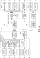
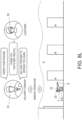
- Fig. 4 is a functional block diagram illustrating one example of a configuration of a control system of the unmanned delivery system 100 of Fig. 1 .
- the unmanned delivery system 100 includes the operating unit controller 301, the robot controller 201, and the drone controller 101.
- the operating unit controller 301 includes a robot manipulate signal generating unit 302, a drone manipulate signal generating unit 303, a display controlling unit 304, a microphone IF 305, a headphone IF 306, an operating unit communicating unit 307, and a camera controlling unit 308.
- the operating unit communicating unit 307 includes a communicator which is capable of performing data communications.
- the robot manipulate signal generating unit 302 the drone manipulate signal generating unit 303, the display controlling unit 304, the microphone IF 305, the headphone IF 306, and the camera controlling unit 308 are realized by a computing element including the processor Pr1 and the memory Me1.
- this computing element includes a microcontroller, an MPU, an FPGA (Field Programmable Gate Array), or a PLC (Programmable Logic Controller), for example. These may be realized by a sole computing element which performs a centralized control, or may be realized by a plurality of computing elements which perform a distributed control.
- the robot manipulate signal generating unit 62 generates a robot manipulate signal according to operation of the robot interface 31.
- the drone manipulate signal generating unit 303 generates a drone manipulate signal according to operation of the drone interface 32.
- the display controlling unit 304 displays an image according to an image signal transmitted from the operating unit communicating unit 307 on the operator's display 33.
- the microphone IF 305 converts the voice acquired by the operator's microphone 34 into a suitable audio signal.
- the headphone IF 306 causes the operator's speaker to output audio according to the audio signal transmitted from the operating unit communicating unit 307.
- the camera controlling unit 308 generates an image signal of the image captured by the operator's camera 36.
- the operating unit communicating unit 307 converts the robot manipulate signal transmitted from the robot manipulate signal generating unit 302, the drone manipulate signal transmitted from the drone manipulate signal generating unit 303, the audio signal transmitted from the microphone IF 305, and the image signal transmitted from the camera controlling unit 308 into wireless-communication signals, and wirelessly transmits the wireless-communication signals. Further, the operating unit communicating unit 307 receives the wireless-communication signals transmitted from a robot communicating unit 202, converts each signal into an image signal or an audio signal, and then transmits the image signal(s) to the display controlling unit 304 and transmits the audio signal(s) to the microphone IF 305. Further, the operating unit communicating unit 307 receives the wireless-communication signals transmitted from a drone communicating unit 102, converts them into information signals, and transmits them to the display controlling unit 304.
- the robot controller 201 includes the robot communicating unit 202, a robot controlling unit 203, and a memory unit 204.
- the robot communicating unit 202 includes a communicator capable of performing data communications.
- the robot controlling unit 203 and the memory unit 204 are realized by a computing element including the processor Pr2 and the memory Me2.
- the robot controlling unit 203 and the memory unit 204 are functional blocks implemented in this computing element by the processor Pr2 executing a control program stored in the memory Me2.
- this computing element is included in a microcontroller, an MPU, an FPGA (Field Programmable Gate Array), or a PLC (Programmable Logic Controller). These may be realized by a sole computing element which performs a centralized control, or may be realized by a plurality of computing elements which perform a distributed control.
- the robot communicating unit 202 receives the wireless-communication signals transmitted from the operating unit communicating unit 307, converts each signal into a robot manipulate signal, an image signal, or an audio signal, and transmits these signals to the robot controlling unit 203.
- the robot controlling unit 203 controls operation of the robot 2 according to the robot manipulate signal, and displays an image according to the image signal on the customer's display 23, and causes the customer's speaker to output audio according to the audio signal.
- the drone controller 101 includes the drone communicating unit 102 and a drone controlling unit 103.
- the drone communicating unit 102 includes a communicator capable of performing data communications.
- the drone controlling unit 103 is realized by a computing element including the processor Pr3 and the memory Me3.
- the drone controlling unit 103 is a functional block implemented in this computing element by the processor Pr3 executing a control program stored in the memory Me3.
- this computing element is included in a microcontroller, an MPU, an FPGA (Field Programmable Gate Array), or a PLC (Programmable Logic Controller), for example. These may be realized by a sole computing element which performs a centralized control, or may be realized by a plurality of computing elements which perform a distributed control.
- the drone communicating unit 102 receives the wireless-communication signals transmitted from the operating unit communicating unit 65, converts them into drone manipulate signals, and transmits them to the drone controlling unit 103. Further, the drone communicating unit 102 converts the information signals transmitted from the drone controlling unit 103 into wireless-communication signals, and wirelessly transmits them.
- the drone controlling unit 103 controls operation of a drone main body 12 and the hoist 11 of the drone 1 according to the drone manipulate signals transmitted from a drone-side communicating unit 82.
- the drone controlling unit 103 transmits the field-of-view image captured by the field-of-view camera of the drone 1, the information, such as the position, the speed, and the fuel amount, required for controlling the drone 1, and the navigation image to the drone communicating unit 102, as information signals.
- a function of one element disclosed herein may be performed using circuitry or processing circuitry including a general-purpose processor, a dedicated processor, an integrated circuit, an ASIC (Application Specific Integrated Circuits), a conventional circuit, and/or a combination thereof, which is configured or programmed to perform the disclosed function. Since the processor includes transistors and other circuitry, it is considered to be the processing circuitry or the circuitry.
- “module” or “unit” is hardware which performs the listed functions, or hardware programmed to perform the listed functions.
- the hardware may be hardware disclosed herein, or may be other known hardware programmed or configured to perform the listed functions.
- the "module” or the “unit” is a combination of hardware and software, and the software is used for the configuration of the hardware and/or the processor.
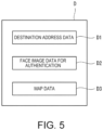
- Fig. 5 is a schematic diagram illustrating one example of delivery data D stored in the memory unit 204 of the robot controller 201.
- the delivery data D includes destination address data D1, face image data D2 for authentication, and map data D3, for example.
- the destination address data D1 is a list of destination addresses.
- the face image data D2 for authentication is a face image data of the addressee P2 at the destination, and it is acquired from a client for the delivery when the delivery is accepted, and it is stored in the memory unit 204 of the robot controller 201. This face image data for authentication is stored so as to correspond to the destination address data D1.
- the map data D3 is used for the delivery by the robot 2.
- the robot controlling unit 203 of the robot controller 201 changes operation between an autonomous operation and a remote operation to control the robot 2.
- the remote operation means manipulation using the robot interface 31 (in detail, operation which follows the robot manipulate signal).
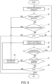
- Fig. 6 is a flowchart illustrating one example of contents of an autonomous operation / remote operation switchover control.
- the robot controlling unit 203 causes the robot 2 to perform the autonomous operation (i.e., autonomous drive) (Step S1).
- the robot controlling unit 203 determines whether a remote command is inputted (Step S2).
- the remote command is included in the robot manipulate signal.
- the robot controlling unit 203 causes the robot 2 to perform the remote operation (i.e., remote drive) (Step S5).
- Step S3 the robot controlling unit 203 determines whether a given condition is satisfied.
- This given condition is that, for example, a route to the receiver's address for the package is a rough terrain 6 (see Fig. 8F ) illustrated in Fig. 8F , or a person approaches the robot 2.
- the robot controlling unit 203 causes the robot 2 to perform the remote operation (i.e., remote drive) (Step S5).
- the robot controlling unit 203 determines whether a termination command is inputted (Step S4).
- the termination command is included in the robot manipulate signal.
- Step S4 If the termination command is not included (NO at Step S4), the robot controlling unit 203 returns this control to Step S1.
- the robot controlling unit 203 ends this control.
- the robot controlling unit 203 determines whether the autonomous command is inputted (Step S6).
- the autonomous command is included in the robot manipulate signal.
- Step S6 If the autonomous command is included (YES at Step S6), the robot controlling unit 203 returns this control to Step S 1.
- the robot controlling unit 203 determines whether an authentication command is inputted (Step S7).
- the authentication command is included in the robot manipulate signal.
- the robot controlling unit 203 performs a face recognition (Step S8).
- the face recognition is performed by the robot controlling unit 203 comparing the face image data stored in the memory unit 204 with the image of the addressee P2 which is imaged by the field-of-view camera 26.
- Well-known methods can be used for the face recognition. Therefore, the explanation is omitted.
- the robot controlling unit 203 After the face recognition is finished, the robot controlling unit 203 returns the operation of the robot 2 back to the remote operation (Step S5). In this case, if the face recognition is successful, the delivery of the package is proceeded, and if the face recognition is not successful, the delivery is suitably processed by a conversation between the operator P1 and the addressee P2.
- the robot controlling unit 203 determines whether the termination command is inputted (Step S9).
- Step S9 If the termination command is not included (NO at Step S9), the robot controlling unit 203 returns this control to Step S5.
- the robot controlling unit 203 ends this control.
- the robot controlling unit 203 carries out image processing of the image captured by the field-of-view camera 26, and determines whether a person exists in the image. Since a method of extracting a person in the image by the image processing is well known, the explanation is omitted herein.
- the robot controlling unit 203 moves the robot 2 in the opposite direction from the person's image. Whether or not the person's image approaches the field-of-view camera is determined, for example, based on the size and the enlarging speed of the person's image.
- Figs. 1 to 8L operation of the unmanned delivery system 100 configured as described above is described using Figs. 1 to 8L .
- the operation of the unmanned delivery system 100 means an unmanned delivery method.
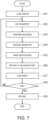
- Fig. 7 is a flowchart illustrating one example of the operation of the unmanned delivery system 100 of Fig. 1 .
- Figs. 8A to 8L are schematic diagrams illustrating one example of the operation of the unmanned delivery system 100 of Fig. 1 step by step.
- the drone 1 is operated by the operator P1
- the robot 2 is autonomously operated or remotely operated by the robot controlling unit 203 of the robot controller 201.
- Step S11 loading of the cargos is first performed at the logistics base 5 (Step S11). This loading has three modes.
- a first mode as illustrated in Fig. 8A , the cargo door 13 of the drone 1 is opened by the operator P1, and the package G is carried or loaded into the drone 1 through the cargo door 13 by a conveyance vehicle 14. In this case, the robot 2 gets into the drone 1 through the cargo door 13.
- the package G is carried into the drone 1 by the conveyance vehicle 14.
- the robot 2 is carried into the drone 1 by the winch 11.
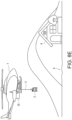
- the drone 1 hovers (i.e., a hovering state), and the hoist door 15 is opened.
- Hooked parts with which hooks at tip ends of wires of the winch 11 engage are disposed at the four corners of an upper surface the traveller 21 of the robot 2.
- the robot 2 carries out the autonomous operation, and it engages the hooks at the tip ends of the wires with the hooked parts by itself. Further, as illustrated in Fig. 8B , the robot 2 takes a given storing posture.
- sensors are disposed at the four hooked parts of the traveller 21 of the robot 2, and the robot controlling unit 203 carries out confirmation that the hooks at the tip ends of the wires are engaged with the hooked parts based on signals from the sensors. Then, it transmits a signal indicative thereof to the operating unit communicating unit 307. Then, this information is displayed on the operator's display 33.
- the operator P1 winds up the winch 11 to carry the robot 2 into the drone 1. Then, the hoist door 15 is closed.
- the robot 2 accommodates the package G in the accommodating unit 212, and, similarly to the second mode, it is carried into the drone 1 by the winch 11.
- the robot 2 puts the carried-in package G on the load rack 17 inside the storage 16 by the remote operation.
- the robot 2 takes out the package G from the accommodating unit 212 and puts it on the load rack 17.
- the robot 2 When the operation is finished, by the autonomous operation, the robot 2 charges the secondary battery 28 with the power from the drone 1, and then fixes itself to the storage 16 by using a suitable apparatus and takes the given storing posture described above.
- Step S12 the package G and the robot 2 are airlifted (Step S12).
- the package G is delivered to a plurality of receiver's addresses 4.
- unloading is performed at an intermediate location on the way to the receiver's address 4 (Step S13).
- the unloading is performed by lowering the robot by using the winch 11, while the drone 1 hovers. This lowering is performed by the operator P1 while checking the ground situation by looking at the field-of-view image captured by the field-of-view camera of the drone 1 and displayed on the operator's display 33. This is for securing the safety.
- the altitude of the drone 1 is more than a given altitude.
- the given altitude is set suitably, and it may be 20m, for example.
- the robot 2 cancels the storing posture by the autonomous operation, and then accommodates the package G to be delivered from then on in the load accommodating unit 212, by the remote operation.
- the package G is transported on the ground by the robot 2 to the receiver's address (Step S14).
- the drone 1 stands by up in the sky until the robot 2 returns.
- the robot 2 travels on a suburban road, while looking up map data by the autonomous operation. Then, on the way, if it encounters the rough terrain 6, the operation is switched to the remote operation, and the robot 2 travels in accordance with the manipulation of the operator P1.
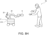
- Step S15 when the robot 2 arrives at the receiver's address 4, it then hands over the package G (Step S15).
- the operation is switched to the remote operation by the manipulation of the operator P1, and the robot 2 then pushes an interphone of the receiver's address 4, and performs the face recognition when the addressee (i.e., a customer) P2 appears. Then, when the addressee P2 approaches, the robot 2 stops automatically, and it will not move unless there is a trigger. From this state, the operation is switched to the remote operation automatically, and the robot 2 hands over the package G to the addressee P2.
- the addressee i.e., a customer
- the robot 2 automatically takes a given load presenting posture. If the addressee P2 approaches too much, the robot 2 automatically moves away from the addressee P2. In this case, the robot 2 has a conversation with the addressee P2.
- the robot controlling unit 203 causes the customer's speaker 25 to output the voice of the operator P1 acquired by the operator's microphone 34, displays the image of the operator P1 captured by the operator's camera 36 on the customer's display 23, causes the operator's speaker 35 to output the voice of the addressee P2 acquired by the customer's microphone 24, and displays the image of the addressee P2 captured by the field-of-view camera 26 on the customer's display 23 so that the addressee P2 and the operator P1 have a conversation.
- This conversation may be as follows, for example.
- the robot 2 returns to the unloading point similarly to the outward trip (Step S 16). Then, the robot 2 is carried into the drone 1 which has been standing by (Step S17).
- the mode of loading the robot 2 is the same as the second mode of the loading at Step S 11.
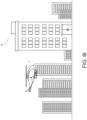
- the receiver's address 4 is one of rooms in a high-rise condominium.
- the drone 1 When the drone 1 reaches above the high-rise condominium, it lowers the robot 2 on the roof.
- a first lowering mode is the same as in the case where the receiver's address 4 is in the suburbs.
- the drone 1 In a second lowering mode, the drone 1 lands on the roof and the robot 2 then gets down to the roof from the opened cargo door 13.
- the package G is carried inside the condominium (i.e., transported on the ground) to the receiver's address 4 by the robot 2 (Step S 14).
- the drone 1 stands by up in the sky until the robot 2 returns.
- the robot 2 is remotely operated.
- the robot 2 gets down to a target story of the high-rise condominium by using an elevator. In this case, the door of the elevator is opened and closed wirelessly by the robot 2.
- the robot 2 arrives at the roof by the autonomous operation which includes occasional remote operations. Then, the robot 2 is carried into the drone 1 which has been standing by (Step S17). The mode of loading of the robot 2 is the same as the second mode of loading at Step S 11.
- a delivery operation to the next receiver's address 4 is performed similarly to the above, and after the delivery operations to all the receiver's addresses 4 are finished, the drone 1 returns to the logistics base 5 (Steps S18 and S 19).
- the robot 2 is disposed at a location on the way to the above-described receiver's address 4. In this case, the robot 2 may remain in the place, or may be collected by the drone 1.
- the delivery of the package G to the addressee P2 can be performed smoothly. Further, as for the robot 2, by performing a comparatively easy work by the autonomous operation and performing a comparatively difficult work by the remote operation, the unmanned delivery can be performed more easily.
- An unmanned delivery system of Embodiment 2 differs from the unmanned delivery system 100 of Embodiment 1 in that the robot 2A is used instead of using the robot 2 of Embodiment 1, and, except for that, it is the same as the unmanned delivery system 100 of Embodiment 1.
- Fig. 9A is a side view illustrating one example of a configuration of the robot 2A used for the unmanned delivery system according to Embodiment 2 of the present disclosure.
- Fig. 9B is a plan view illustrating one example of the configuration of the robot 2A used for the unmanned delivery system according to Embodiment 2 of the present disclosure.
- the robot 2A includes the traveller 21 and the pair of robotic arms 22 disposed on the traveller 21.
- the traveller 21 may be a cart or carrier.
- the pair of robotic arms 22 each include a four-axis vertical articulated robotic arm. That is, each robotic arm 22 includes a first link L1 rotatable on a vertical first rotation axis Ax 1 . This first link L1 is common to the both robotic arms 22.
- a base-end part of a second link L2 is disposed at a tip-end part of the first link L1 so as to be rotatable on a second rotation axis Ax 2 perpendicular to the first rotation axis Ax 1 .
- a base-end part of a third link L3 is disposed at a tip-end part of the second link L2 so as to be rotatable on a third rotation axis Ax 3 perpendicular to the second rotation axis Ax 2 .
- a base-end part of a fourth link L4 is disposed at a tip-end part of the third link L3 so as to be rotatable on a fourth rotation axis Ax 4 perpendicular to the third rotation axis Ax 3 .
- the gripper 221 including the three pawls 222 is disposed at a tip end of the fourth link L4.
- the pair of robotic arms 22 grasp the package G by the pair of grippers 221.
- the traveller 21 of the robot 2 is formed in a cart shape, and includes the load accommodating unit 212 in a front end part.
- the load accommodating unit 212 is formed in a rectangular box shape including a bottom wall 212a and a side wall 212b, in which an upper surface is opened. An upper part of a rear wall part of the load accommodating unit 212 is removed so that the pair of robotic arms 22 can put the package G into the package accommodating unit from the removed part.
- the pair of front wheels 211 and the pair of rear wheels 211 are disposed at the bottom part of the traveller 21. For example, either the pair of front wheels 211 or the pair of rear wheels 211 are steering wheels, and either the pair of front wheels 211 or the pair of rear wheels 211 are driving wheels.
- the secondary battery 28 and the motor are mounted on the traveller 21, and the motor drives the driving wheels by using the secondary battery 28 as a power source. Further, a pair of outriggers 213 are disposed at both sides of a center part of the traveller 21. The outriggers 213 are configured to be accommodatable inside the traveller 21. When the robot 2A stops and performs loading and unloading the package G, the outriggers 213 project to the left and right from the traveller 21 and push the ground so that the movement of the traveller 21 is prevented.
- the display robotic arm 27 is disposed behind the robotic arm 22 of the traveller 21. Since this display robotic arm 27 is the same as that of Embodiment 1, the explanation is omitted.
- the operator P1 can operate robots 2 of Embodiment 1 or Embodiment 2.
- Other configurations are similar to those of Embodiment 1 or Embodiment 2.
- an unmanned delivery system of Embodiment 3 includes the robots 2.
- An identification symbol is given to each of the robots 2.
- the robot interface 31 includes an interface module for specifying the robot 2 to be manipulated.
- the robot manipulate signal generating unit 302 assigns the identification symbol of the specified robot 2 to the robot manipulate signal according to the operation of the interface module.
- the robot controlling unit 203 of each robot 2 controls the robot 2 based on the robot manipulate signal, when the robot manipulate signal includes the identification symbol of the robot 2 to which itself belongs.
- the operator P1 can manipulate the self-propelled robots 2 by the sole robot interface 31.
- the unmanned delivery can be performed efficiently.
- the self-propelled robot 2 since the self-propelled robot 2 is capable of traveling on the ground and handling the package G, it can smoothly deliver the package G to the addressee P2. Further, since the control of the self-propelled robot 2 is switched between the autonomous operation and the remote operation in which the self-propelled robot 2 is operated in accordance with the manipulation of the robot interface 31, the unmanned delivery can be performed more easily by performing the comparatively easy work by the autonomous operation and performing the comparatively difficult work by the remote operation.
- the robot controller 201 may fundamentally cause the self-propelled robot 2 to perform the autonomous operation, and when a given condition is satisfied, it may cause the self-propelled robot 2 to perform the remote operation.
- the unmanned delivery can be performed more appropriately.
- the given condition may be one of that the route to the receiver's address 4 is the rough terrain 6 and that a person approached the self-propelled robot 2.
- the robot controller 201 may cause the self-propelled robot 2 to perform the remote operation.
- the handing over of the package G at the receiver's address 4, which requires a polite correspondence, can be performed appropriately based on a judgment by a person.
- the robot controller 201 may move the self-propelled robot 2 away from a person as the person approaches the self-propelled robot 2.
- the distance between the person and the self-propelled robot 2 can be maintained within a safe range.
- the self-propelled robot 2 may include the field-of-view camera 26 which images surroundings thereof.
- the robot controller 201 may include face image data for authentication.
- the robot controller 201 may perform the face recognition of the addressee P2 of the package G based on the image captured by the field-of-view camera 26 and the face image data for authentication, and when the face recognition is successful, the robot controller 201 may perform the handover of the package G.
- the unmanned delivery system 100 may include the operating unit 3, and the operating unit 3 may include the robot interface 31, the operator's camera 36 which images the operator P1, the operator's microphone 34 which acquires voice of the operator P1, the operator's display 33, and the operator's speaker 35.
- the self-propelled robot 2 may further include the customer's microphone 24 which acquires voice of the addressee P2, the customer's display 23, and the customer's speaker 25.
- the robot controller 201 may cause the customer's speaker 25 to output the voice of the operator P1 acquired by the operator's microphone 34, display on the customer's display 23 the image of the operator P1 captured by the operator's camera 36, cause the operator's speaker 35 to output the voice of the addressee P2 acquired by the customer's microphone 24, and display on the customer's display 23 the image of the addressee P2 captured by the field-of-view camera 26, so that the addressee P2 and the operator P1 have a conversation.
- the handover can be performed smoothly with the conversation between the addressee P2 and the operator P1.
- the robot controller 201 may include the map data D3, and the robot controller 201 may cause the self-propelled robot 2 to travel by the autonomous operation from the intermediate location to the receiver's address 4 using the map data D3.
- the unmanned delivery system 100 may include the self-propelled robots 2, and the self-propelled robots 2 and the robot interface 31 may be configured so that the self-propelled robots 2 are operable by the sole robot interface 31.
- the unmanned delivery can be performed efficiently.
Landscapes
- Engineering & Computer Science (AREA)
- Mechanical Engineering (AREA)
- Robotics (AREA)
- Business, Economics & Management (AREA)
- Physics & Mathematics (AREA)
- General Physics & Mathematics (AREA)
- Economics (AREA)
- Remote Sensing (AREA)
- Aviation & Aerospace Engineering (AREA)
- Theoretical Computer Science (AREA)
- Human Computer Interaction (AREA)
- Multimedia (AREA)
- Development Economics (AREA)
- Entrepreneurship & Innovation (AREA)
- Operations Research (AREA)
- General Business, Economics & Management (AREA)
- Marketing (AREA)
- Human Resources & Organizations (AREA)
- Quality & Reliability (AREA)
- Strategic Management (AREA)
- Tourism & Hospitality (AREA)
- Radar, Positioning & Navigation (AREA)
- Acoustics & Sound (AREA)
- General Health & Medical Sciences (AREA)
- Oral & Maxillofacial Surgery (AREA)
- Health & Medical Sciences (AREA)
- Automation & Control Theory (AREA)
- Manipulator (AREA)
- Control Of Position, Course, Altitude, Or Attitude Of Moving Bodies (AREA)
Applications Claiming Priority (2)
| Application Number | Priority Date | Filing Date | Title |
|---|---|---|---|
| JP2020183352A JP7522007B2 (ja) | 2020-10-30 | 2020-10-30 | 無人配送システム及び無人配送方法 |
| PCT/JP2021/038760 WO2022091907A1 (ja) | 2020-10-30 | 2021-10-20 | 無人配送システム及び無人配送方法 |
Publications (2)
| Publication Number | Publication Date |
|---|---|
| EP4238914A1 true EP4238914A1 (de) | 2023-09-06 |
| EP4238914A4 EP4238914A4 (de) | 2024-06-12 |
Family
ID=81382385
Family Applications (1)
| Application Number | Title | Priority Date | Filing Date |
|---|---|---|---|
| EP21886026.0A Pending EP4238914A4 (de) | 2020-10-30 | 2021-10-20 | Unbemanntes liefersystem und unbemanntes lieferverfahren |
Country Status (6)
| Country | Link |
|---|---|
| US (1) | US20230405830A1 (de) |
| EP (1) | EP4238914A4 (de) |
| JP (1) | JP7522007B2 (de) |
| KR (1) | KR102941284B1 (de) |
| CN (1) | CN116507569A (de) |
| WO (1) | WO2022091907A1 (de) |
Families Citing this family (4)
| Publication number | Priority date | Publication date | Assignee | Title |
|---|---|---|---|---|
| WO2019178172A1 (en) * | 2018-03-14 | 2019-09-19 | Fedex Corporate Services, Inc. | A modular autonomous bot apparatus assembly for transporting an item being shipped |
| JP7532214B2 (ja) * | 2020-10-30 | 2024-08-13 | 川崎重工業株式会社 | 自走ロボット及びそれを備える物品搬送システム |
| US12380754B2 (en) | 2021-02-25 | 2025-08-05 | Federal Express Corporation | Methods and apparatus for providing enhanced automated access to a dispatched personal delivery device operative to transport a shipment item |
| WO2023040897A1 (zh) * | 2021-09-14 | 2023-03-23 | 武汉联影智融医疗科技有限公司 | 一种手术机器人的空间注册位姿计算方法和系统 |
Family Cites Families (79)
| Publication number | Priority date | Publication date | Assignee | Title |
|---|---|---|---|---|
| US20040162637A1 (en) * | 2002-07-25 | 2004-08-19 | Yulun Wang | Medical tele-robotic system with a master remote station with an arbitrator |
| US20140254896A1 (en) * | 2011-07-18 | 2014-09-11 | Tiger T G Zhou | Unmanned drone, robot system for delivering mail, goods, humanoid security, crisis negotiation, mobile payments, smart humanoid mailbox and wearable personal exoskeleton heavy load flying machine |
| TW201249713A (en) * | 2011-06-02 | 2012-12-16 | Hon Hai Prec Ind Co Ltd | Unmanned aerial vehicle control system and method |
| US9384668B2 (en) * | 2012-05-09 | 2016-07-05 | Singularity University | Transportation using network of unmanned aerial vehicles |
| US9014874B2 (en) * | 2013-01-29 | 2015-04-21 | Foster-Miller, Inc. | Tactical robot controller |
| JP6158665B2 (ja) | 2013-09-27 | 2017-07-05 | 本田技研工業株式会社 | ロボット、ロボット制御方法、およびロボット制御プログラム |
| US10723442B2 (en) * | 2013-12-26 | 2020-07-28 | Flir Detection, Inc. | Adaptive thrust vector unmanned aerial vehicle |
| US10839336B2 (en) * | 2013-12-26 | 2020-11-17 | Flir Detection, Inc. | Unmanned delivery |
| US9868526B2 (en) * | 2014-10-15 | 2018-01-16 | W. Morrison Consulting Group, Inc. | Airborne drone delivery network and method of operating same |
| JP6558764B2 (ja) | 2014-10-23 | 2019-08-14 | 公立大学法人首都大学東京 | テレプレゼンスロボット |
| US9305280B1 (en) * | 2014-12-22 | 2016-04-05 | Amazon Technologies, Inc. | Airborne fulfillment center utilizing unmanned aerial vehicles for item delivery |
| US9915956B2 (en) * | 2015-01-09 | 2018-03-13 | Workhorse Group Inc. | Package delivery by means of an automated multi-copter UAS/UAV dispatched from a conventional delivery vehicle |
| US9747901B1 (en) * | 2015-02-27 | 2017-08-29 | Amazon Technologies, Inc. | Speech interaction for unmanned aerial vehicles |
| US9488979B1 (en) * | 2015-04-14 | 2016-11-08 | Zipline International Inc. | System and method for human operator intervention in autonomous vehicle operations |
| US20170038780A1 (en) * | 2015-08-04 | 2017-02-09 | Gerald N. Fandetti | Method of drone delivery using aircraft |
| DE102015013104A1 (de) * | 2015-08-22 | 2017-02-23 | Dania Lieselotte Reuter | Verfahren zur Zielanflungsteuerung von unbemannten Flugobjekten, insbesondere Lieferdrohen |
| CN105046835A (zh) * | 2015-08-26 | 2015-11-11 | 广州极飞电子科技有限公司 | 物品接收方法和装置、物品投递方法及系统 |
| US9969080B2 (en) * | 2016-08-02 | 2018-05-15 | Accel Robotics | Robotic camera system |
| US10078808B1 (en) * | 2015-09-21 | 2018-09-18 | Amazon Technologies, Inc. | On-demand designated delivery locator |
| US9630712B1 (en) * | 2015-09-23 | 2017-04-25 | Amazon Technologies, Inc. | Using multirotor lifters to deploy fixed wing aircraft |
| US20170255896A1 (en) * | 2016-03-04 | 2017-09-07 | Jesse Van Dyke | Unattended Delivery Drop Box |
| US9969494B1 (en) * | 2015-09-28 | 2018-05-15 | Amazon Technologies, Inc. | Delivery drop platforms, tethers, and stabilization |
| US10071804B1 (en) * | 2015-09-28 | 2018-09-11 | Amazon Technologies, Inc. | Delivery drop rate modulation |
| CN108139754A (zh) * | 2015-10-13 | 2018-06-08 | 星船科技私人有限公司 | 用于自主或半自主递送的方法和系统 |
| US9841757B2 (en) * | 2015-12-03 | 2017-12-12 | At&T Intellectual Property I, L.P. | Drone piggybacking on vehicles |
| JP6084675B1 (ja) * | 2015-12-07 | 2017-02-22 | 賀子 高木 | 無人飛行体を用いた輸送システム |
| US9646597B1 (en) * | 2015-12-21 | 2017-05-09 | Amazon Technologies, Inc. | Delivery sound masking and sound emission |
| WO2017115446A1 (ja) * | 2015-12-29 | 2017-07-06 | 楽天株式会社 | 物流システム、荷物運搬方法、及びプログラム |
| US11488089B2 (en) * | 2015-12-29 | 2022-11-01 | Rakuten Group, Inc. | Logistics system, package delivery method, and program |
| WO2017152067A1 (en) * | 2016-03-04 | 2017-09-08 | Animusoft Llc | Drone and robot control systems and methods |
| JP6402320B2 (ja) * | 2016-04-08 | 2018-10-10 | Groove X株式会社 | 人見知りする自律行動型ロボット |
| DE112017002589T5 (de) * | 2016-05-20 | 2019-04-25 | Groove X, Inc. | Autonom handelnder Roboter und Computerprogramm |
| US9984579B1 (en) * | 2016-06-28 | 2018-05-29 | Amazon Technologies, Inc. | Unmanned aerial vehicle approach notification |
| US10249200B1 (en) * | 2016-07-22 | 2019-04-02 | Amazon Technologies, Inc. | Deployable delivery guidance |
| US11880784B2 (en) | 2016-08-05 | 2024-01-23 | Starship Technologies Oü | System and mobile freight station and method for distribution, delivery, and collection of freight |
| WO2018027220A1 (en) * | 2016-08-05 | 2018-02-08 | Christopher Wilkinson | Law enforcement drone |
| CN106054901A (zh) * | 2016-08-18 | 2016-10-26 | 沈阳凤天机器人科技有限公司 | 自主移动售卖机器人 |
| JP2018030407A (ja) * | 2016-08-23 | 2018-03-01 | 株式会社日立製作所 | 搬送システム及び搬送方法 |
| JP6472113B2 (ja) * | 2016-09-08 | 2019-02-20 | Groove X株式会社 | 自然な距離感を保つ自律行動型ロボットおよびプログラム |
| US10789567B1 (en) * | 2016-10-07 | 2020-09-29 | Shmuel Ur Innovation Ltd | Drone based delivery system using vehicles |
| US20200286034A1 (en) * | 2017-09-25 | 2020-09-10 | Shmuel Ur Innovation Ltd | Drone based delivery system using vehicles |
| US12444258B2 (en) * | 2022-05-13 | 2025-10-14 | 1Ahead Technologies | Entry management system |
| KR101753555B1 (ko) * | 2017-02-13 | 2017-07-03 | 주식회사 평강비아이엠 | 긴급구난용 특수차량의 통합제어 시스템 |
| KR102023399B1 (ko) * | 2017-04-11 | 2019-11-04 | 경희대학교 산학협력단 | 하수도 탐색을 위한 드론 제어 시스템 및 방법 |
| US11874661B2 (en) * | 2017-04-21 | 2024-01-16 | Rakuten Group, Inc. | Battery installation system, battery installation method, and program |
| US10706381B2 (en) * | 2017-07-05 | 2020-07-07 | Omnitracs, Llc | Vehicle and drone management system |
| CA3070300A1 (en) * | 2017-07-28 | 2019-01-31 | Nuro, Inc. | Food and beverage delivery system on autonomous and semi-autonomous vehicle |
| JP2019028838A (ja) | 2017-08-01 | 2019-02-21 | パナソニックIpマネジメント株式会社 | 配送管理システムおよび配送管理方法 |
| US10545500B2 (en) * | 2017-08-02 | 2020-01-28 | Wing Aviation Llc | Model for determining drop-off spot at delivery location |
| US10916151B2 (en) * | 2017-08-02 | 2021-02-09 | Microsoft Technology Licensing, Llc | En route product delivery by unmanned aerial vehicles |
| US11127305B2 (en) * | 2017-10-27 | 2021-09-21 | Drone Delivery Canada Corp. | Unmanned aerial vehicle delivery system for delivery of medical or emergency supplies |
| US10649460B2 (en) * | 2017-11-14 | 2020-05-12 | Facebook, Inc. | Interactive robots positionable for optimal interactions |
| US10690525B2 (en) * | 2018-01-03 | 2020-06-23 | General Electric Company | Systems and methods associated with unmanned aerial vehicle targeting accuracy |
| US10809745B2 (en) * | 2018-01-15 | 2020-10-20 | Motogo, Llc | System and method of last mile delivery |
| WO2019152674A2 (en) * | 2018-01-31 | 2019-08-08 | Walmart Apollo, Llc | System and method for coordinating unmanned aerial vehicles for delivery of one or more packages |
| KR102285813B1 (ko) * | 2018-11-02 | 2021-08-04 | 주식회사 도구공간 | 이동 로봇의 제어 방법, 그 방법을 지원하는 장치 및 이동 로봇을 이용한 배송 시스템 |
| JP2019161266A (ja) * | 2018-03-07 | 2019-09-19 | シャープ株式会社 | 画像撮影装置の制御装置、画像撮影装置、制御プログラム、および画像撮影装置の制御方法 |
| US20190295526A1 (en) * | 2018-03-26 | 2019-09-26 | Casio Computer Co., Ltd. | Dialogue control device, dialogue system, dialogue control method, and recording medium |
| CN110471403B (zh) * | 2018-05-09 | 2023-11-03 | 北京外号信息技术有限公司 | 通过光通信装置对能够自主移动的机器进行导引的方法 |
| US20190352005A1 (en) * | 2018-05-18 | 2019-11-21 | Qualcomm Incorporated | Fiducial gates for drone racing |
| US20190354099A1 (en) * | 2018-05-18 | 2019-11-21 | Qualcomm Incorporated | Augmenting a robotic vehicle with virtual features |
| US11447055B2 (en) * | 2018-05-22 | 2022-09-20 | Uatc, Llc | Automated delivery systems for autonomous vehicles |
| US20210132625A1 (en) * | 2018-05-31 | 2021-05-06 | Carla R Gillett | Modular delivery vehicle system |
| US10890921B2 (en) * | 2018-05-31 | 2021-01-12 | Carla R. Gillett | Robot and drone array |
| JP7159822B2 (ja) * | 2018-11-29 | 2022-10-25 | トヨタ自動車株式会社 | 配送システム及び処理サーバ |
| JP6748797B1 (ja) * | 2018-12-25 | 2020-09-02 | 楽天株式会社 | 無人航空機制御システム、無人航空機制御方法、及びプログラム |
| CN113226959A (zh) * | 2018-12-27 | 2021-08-06 | 乐天集团股份有限公司 | 物流系统、无人机以及货物管理方法 |
| JP2020128287A (ja) | 2019-02-08 | 2020-08-27 | トヨタ自動車株式会社 | 車両 |
| US11513537B2 (en) * | 2019-05-09 | 2022-11-29 | Toyota Motor Eng & Mfg North America, Inc. | Managing drones in vehicular system |
| KR20190106866A (ko) * | 2019-08-27 | 2019-09-18 | 엘지전자 주식회사 | 로봇 및 로봇에 의해 안내 서비스를 제공하는 방법 |
| WO2021041921A1 (en) * | 2019-08-29 | 2021-03-04 | Here Global B.V. | Method, apparatus, and system for dynamic model or model parameter switching for object detection |
| WO2021090102A1 (en) * | 2019-11-04 | 2021-05-14 | Indian Institute Of Science | System for operating joystick |
| KR102359601B1 (ko) * | 2019-11-29 | 2022-02-08 | 한국과학기술원 | 투명 평판을 이용한 영상 처리 방법 및 이를 수행하는 장치 |
| US11513538B1 (en) * | 2020-04-15 | 2022-11-29 | Express Scripts Strategic Development, Inc. | System and method for thermal control during delivery of a medication package |
| JP7110289B2 (ja) * | 2020-09-04 | 2022-08-01 | 楽天グループ株式会社 | 情報処理装置、情報処理方法、及び情報処理システム |
| US12014574B2 (en) * | 2020-10-26 | 2024-06-18 | The Boeing Company | Human gesture recognition for autonomous aircraft operation |
| JP7532214B2 (ja) * | 2020-10-30 | 2024-08-13 | 川崎重工業株式会社 | 自走ロボット及びそれを備える物品搬送システム |
| KR102352793B1 (ko) * | 2021-03-04 | 2022-01-18 | 주식회사 파블로항공 | 자율 주행 이동체의 협업을 통한 물품 배송 방법 및 장치 |
| US20250013974A1 (en) * | 2023-07-07 | 2025-01-09 | Quoc Viet Luong | System and methods for full automation of door-to-door delivery and pickup of postal packages to/from residents in high-rise building complexes using drone-robot combinations |
-
2020
- 2020-10-30 JP JP2020183352A patent/JP7522007B2/ja active Active
-
2021
- 2021-10-20 CN CN202180073800.4A patent/CN116507569A/zh active Pending
- 2021-10-20 US US18/034,093 patent/US20230405830A1/en active Pending
- 2021-10-20 KR KR1020237014893A patent/KR102941284B1/ko active Active
- 2021-10-20 WO PCT/JP2021/038760 patent/WO2022091907A1/ja not_active Ceased
- 2021-10-20 EP EP21886026.0A patent/EP4238914A4/de active Pending
Also Published As
| Publication number | Publication date |
|---|---|
| CN116507569A (zh) | 2023-07-28 |
| JP7522007B2 (ja) | 2024-07-24 |
| US20230405830A1 (en) | 2023-12-21 |
| KR102941284B1 (ko) | 2026-03-19 |
| WO2022091907A1 (ja) | 2022-05-05 |
| JP2022073395A (ja) | 2022-05-17 |
| KR20230079423A (ko) | 2023-06-07 |
| EP4238914A4 (de) | 2024-06-12 |
Similar Documents
| Publication | Publication Date | Title |
|---|---|---|
| EP4238914A1 (de) | Unbemanntes liefersystem und unbemanntes lieferverfahren | |
| JP4222510B2 (ja) | 無人飛行体による運搬方法 | |
| US20230249820A1 (en) | Control of drone-load system method, system, and apparatus | |
| US6826452B1 (en) | Cable array robot for material handling | |
| JP7159822B2 (ja) | 配送システム及び処理サーバ | |
| US9440577B2 (en) | Vehicle wrecker with improved controls | |
| WO2020107468A1 (zh) | 一种无人设备的控制方法及无人车 | |
| WO2021194628A2 (en) | Control of drone-load system method, system, and apparatus | |
| US12515795B2 (en) | Unmanned delivery system and unmanned delivery method | |
| JP2019219735A (ja) | 自律移動体、および自律移動体の制御プログラム | |
| US20230069643A1 (en) | Flying body and method for transporting load using same | |
| EP4238709A1 (de) | Selbstangetriebener roboter und artikeltransfersystem damit | |
| US20230173694A1 (en) | Autonomous modular robots and methods of use | |
| JP2022073837A (ja) | 無人配送システム及び無人配送方法 | |
| JP2019048681A (ja) | 荷役搬送システム、荷役搬送装置、および荷役搬送方法 | |
| EP4209417B1 (de) | Zulufthebesystem und zulufthebeverfahren | |
| US20250229420A1 (en) | Multi-purpose robotic platform | |
| JP7237394B1 (ja) | 飛行体 | |
| JP2020179485A (ja) | ロボット、モバイル型の収容装置、及びロボット制御方法 | |
| CN116472143A (zh) | 无人配送系统以及无人配送方法 | |
| US20250128400A1 (en) | Systems and Techniques for Implementing Autonomous Robots and Payload Management Systems | |
| CN119681914A (zh) | 用于太阳能发电场的清洁系统 | |
| WO2021235141A1 (ja) | 移動体及びその制御装置、方法及びプログラム |
Legal Events
| Date | Code | Title | Description |
|---|---|---|---|
| STAA | Information on the status of an ep patent application or granted ep patent |
Free format text: STATUS: THE INTERNATIONAL PUBLICATION HAS BEEN MADE |
|
| PUAI | Public reference made under article 153(3) epc to a published international application that has entered the european phase |
Free format text: ORIGINAL CODE: 0009012 |
|
| STAA | Information on the status of an ep patent application or granted ep patent |
Free format text: STATUS: REQUEST FOR EXAMINATION WAS MADE |
|
| 17P | Request for examination filed |
Effective date: 20230511 |
|
| AK | Designated contracting states |
Kind code of ref document: A1 Designated state(s): AL AT BE BG CH CY CZ DE DK EE ES FI FR GB GR HR HU IE IS IT LI LT LU LV MC MK MT NL NO PL PT RO RS SE SI SK SM TR |
|
| DAV | Request for validation of the european patent (deleted) | ||
| DAX | Request for extension of the european patent (deleted) | ||
| A4 | Supplementary search report drawn up and despatched |
Effective date: 20240514 |
|
| RIC1 | Information provided on ipc code assigned before grant |
Ipc: G06Q 10/083 20240101ALI20240508BHEP Ipc: B25J 13/06 20060101ALI20240508BHEP Ipc: B25J 11/00 20060101ALI20240508BHEP Ipc: G06Q 10/08 20120101ALI20240508BHEP Ipc: G05D 1/00 20060101ALI20240508BHEP Ipc: B64C 39/02 20060101ALI20240508BHEP Ipc: B61B 13/00 20060101ALI20240508BHEP Ipc: B25J 5/00 20060101ALI20240508BHEP Ipc: B65G 61/00 20060101AFI20240508BHEP |
|
| STAA | Information on the status of an ep patent application or granted ep patent |
Free format text: STATUS: EXAMINATION IS IN PROGRESS |
|
| 17Q | First examination report despatched |
Effective date: 20250404 |
|
| GRAP | Despatch of communication of intention to grant a patent |
Free format text: ORIGINAL CODE: EPIDOSNIGR1 |
|
| STAA | Information on the status of an ep patent application or granted ep patent |
Free format text: STATUS: GRANT OF PATENT IS INTENDED |