EP4237606B1 - Stricksystem und nadel für strickmaschinen - Google Patents
Stricksystem und nadel für strickmaschinen Download PDFInfo
- Publication number
- EP4237606B1 EP4237606B1 EP21801891.9A EP21801891A EP4237606B1 EP 4237606 B1 EP4237606 B1 EP 4237606B1 EP 21801891 A EP21801891 A EP 21801891A EP 4237606 B1 EP4237606 B1 EP 4237606B1
- Authority
- EP
- European Patent Office
- Prior art keywords
- needle
- working
- recess
- shank
- guiding
- Prior art date
- Legal status (The legal status is an assumption and is not a legal conclusion. Google has not performed a legal analysis and makes no representation as to the accuracy of the status listed.)
- Active
Links
Images





Classifications
-
- D—TEXTILES; PAPER
- D04—BRAIDING; LACE-MAKING; KNITTING; TRIMMINGS; NON-WOVEN FABRICS
- D04B—KNITTING
- D04B35/00—Details of, or auxiliary devices incorporated in, knitting machines, not otherwise provided for
- D04B35/02—Knitting tools or instruments not provided for in group D04B15/00 or D04B27/00
- D04B35/04—Latch needles
-
- D—TEXTILES; PAPER
- D04—BRAIDING; LACE-MAKING; KNITTING; TRIMMINGS; NON-WOVEN FABRICS
- D04B—KNITTING
- D04B15/00—Details of, or auxiliary devices incorporated in, weft knitting machines, restricted to machines of this kind
- D04B15/10—Needle beds
-
- D—TEXTILES; PAPER
- D04—BRAIDING; LACE-MAKING; KNITTING; TRIMMINGS; NON-WOVEN FABRICS
- D04B—KNITTING
- D04B15/00—Details of, or auxiliary devices incorporated in, weft knitting machines, restricted to machines of this kind
- D04B15/14—Needle cylinders
Definitions
- needle-guiding means comprising grooves in which loop-forming needles are guided and can be moved translatorially in the longitudinal direction of the grooves, which point in the working direction.
- these needle-guiding means are typically knitting cylinders whose basic shape is cylindrical and whose cylinder axis points in the working direction. The grooves are then arranged on a cylindrical base surface of the knitting cylinder.
- these needle-guiding means are typically needle beds having an essentially rectangular shape. The grooves in such needle beds are arranged on a planar base surface of the needle bed, said planar base surface pointing in an elevational direction.
- the elevational direction is at right angles to the working direction.
- Needle beds for flat knitting machines and knitting cylinders for circular knitting machines both constitute needle-guiding means. At their front end, the needles mostly have a loop-forming element - in most cases shaped as a hook - with which loops can be formed during the knitting process.
- the needle-guiding means has a plurality of grooves arranged side by side at a defined distance apart, said distance corresponding to the pitch, along a peripheral direction of the needle-guiding means.
- the peripheral direction in this context is at right angles to the working direction and to the elevational direction and extends along the base area of the needle-guiding means. In the case of a knitting cylinder, therefore, the peripheral direction always runs tangentially along the cylindrical base area of the knitting cylinder.
- Each needle comprises at least one drive butt via which it can be moved translatorially.
- the drive butts of the needles engage with a cam which has a curved profile in the peripheral direction of the needle-guiding means. Relative motion in peripheral direction between cam and needle-guiding means initiates translatory motion in working direction in the drive butts of the needles.
- US5097683A , US2240761A , US664808A show typical needles with hook-shaped loop-forming elements.
- Each needle comprises a bending portion in which the shaft of the needle is bent such that the friction between the needle and the groove is increased when such a needle is used in a groove of a knitting machine.
- the needles shown in US2240761A and US664808A even have a recess within the bending portion. Such needles are designed to be accommodated in just one straight needle groove of a knitting machine.
- WO2012055591A1 and US2015128651A1 both show a knitting machine having needles which, in a rearward shank portion, are guided in slide or guiding grooves and, in a forward working portion, are guided in loop-forming or verge grooves.
- the guiding grooves and verge grooves are arranged on a knitting cylinder, wherein associated guiding and verge grooves are parallel to each other and mutually offset in the peripheral direction of the knitting cylinder.
- Loop-forming needles, each of which is guided in its own guiding groove and its own verge groove, are able to compensate this offset by means of elastic bending.
- the aim of the invention is therefore to devise a knitting system and a needle which show greater stability, are less prone to wear and require less power than previously known knitting systems and needles.
- a knitting system features a needle-guiding means with a base surface pointing in an elevational direction, as well as at least one guiding groove which is arranged on the base surface of the needle-guiding means and extends substantially in working direction, wherein the working direction is at right angles to the elevational direction.
- At least one verge groove is arranged on the base surface of the needle-guiding means and is offset relative to the at least one guiding groove in peripheral direction and in working direction, said peripheral direction extending on the base surface of the needle-guiding means at right angles to the working direction and the elevational direction.
- At least one recess is arranged at at least one of its lateral surfaces pointing in peripheral or in elevational direction and/or the bending portion of the at least one needle is plastically formed in such a manner as to effect, in peripheral direction, a plastic shank offset between the working portion and the shank portion.
- the lateral surfaces are the surfaces bounding the needle in peripheral direction and elevational direction.
- at least two recesses are defined on at least one of its lateral surfaces pointing in peripheral direction or in elevational direction.
- a plurality of recesses may be defined on the same lateral surface or one recess in each case on two lateral surfaces.
- At least one recess is defined on a lateral surface pointing in peripheral direction and at least one recess on a lateral surface pointing in elevational direction.
- the offset in peripheral direction which exists between the verge groove and the guiding groove, is compensated by the needle by means of an elastic or plastic bend in its bending portion. Only in this way is it possible for the shank portion of a needle to be accommodated in a guiding groove and its working portion in a verge groove which is offset in peripheral direction relative to the guiding groove.
- the shank and working portions of a needle which has a recess in the bending portion can be configured with greater stability without necessitating higher bending forces for the bend in the bending portion.
- the needle height for example, can be increased.
- increased needle height in the shank portion enables driving forces, in particular, which are transmitted from the cam to the needle's drive butt, to be supported better in the guiding channel with lower supporting forces. Consequently, a needle of this kind not only shows greater stability but is also less prone to wear and requires less power.
- the guiding and verge grooves may be manufactured in different ways: for example, they may be introduced into the needle-guiding means by means of a machining method. It is also possible for the grooves - both guiding grooves and verge grooves - to be formed by walls inserted in the base surface, which project above the base surface and form grooves with neighbouring walls.
- the knitting system according to the invention may comprise guiding and verge grooves made by all production and construction methods previously known for this purpose.
- the following applies it is advantageous to produce the recess by means of machining processes, such as grinding or milling, and/or forming processes, such as rolling, and/or parting processes, such as punching.
- a ground recess is particularly advantageous. Recesses produced by machining and forming methods, in particular ground recesses, can be made inexpensively and accurately. In the area of recesses, the needle's cross section is less than in surrounding areas.
- At least one recess at a lateral surface pointing in peripheral direction has a recess depth of 10 ⁇ m to 100 ⁇ m, advantageously 30 ⁇ m to 70 ⁇ m, and/or at least one recess at a lateral surface pointing in elevational direction has a recess depth of 150 ⁇ m to 500 ⁇ m, advantageously 200 ⁇ m to 400 ⁇ m.
- the recess depth here is the depth to which the recess surface is sunk below the lateral surface on which the recess is defined.
- the recess surface also points in peripheral direction, and in the case of a recess on a lateral surface pointing in elevational direction, the recess surface also points in the elevational direction. If the recess were too deep, the needle would be weakened too much in the bending portion. This would then prevent exploitation of the advantages resulting, particularly in the shank portion, from the improved support of the needle on on account of the driving forces. If, on the other hand, the recess is not deep enough, the stability of the needle in the shank portion and working portion cannot be sufficiently improved.
- the above-mentioned selection ranges have proved advantageous with customary needle widths of less than 0.6 mm and needle heights of less than 4 mm.
- the at least one recess extends, in an elevational direction which is at right angles to the working direction and the peripheral direction, over the entire needle height.
- a recess which extends over the entire needle height requires less complex production methods than a recess which only extends over part of the needle height.
- a recess which extends over a maximum of 90%, preferably a maximum of 80%, of the needle height is also advantageous.
- the bending properties of the needle can also be optimized with a recess which does not extend over the entire needle height.
- the at least one recess extends, in working direction, over the entire bending portion of the needle.
- the length of the bending portion in working direction is therefore the same as a recess length corresponding to the extension of the recess in working direction. Additional advantages are obtained if the at least one recess extends in working direction over a maximum of 80%, preferably a maximum of 50%, of the bending portion.
- the recess length is thus less than the length of the bending portion in working direction.
- the needle may also be bent at places where there is no recess.
- at least two recesses are defined on one of the needle's lateral surfaces pointing in the peripheral direction. A plurality of recesses is thus defined on the same lateral surface. It is also possible to define more than one recess in each case on a plurality of lateral surfaces. It is advantageous if the at least two recesses provided on a lateral surface are spaced from one another in working direction and/or elevational direction.
- the at least one recess of the at least one needle in an extended state and/or a retracted state, is completely outside the at least one verge groove and/or the at least one guiding groove.
- the needles are translatorially movable in working direction in the verge and guiding grooves.
- the extended state of the needle in this case is the state in which the needle's loop-forming element projects furthest out of the verge groove in working direction.
- the retracted state of the needle is the state in which the loop-forming element projects the shortest distance out of the verge groove in working direction.
- the working portion is accommodated in a verge groove and the shank portion in a guiding groove.
- the knitting system is configured in such a manner that a recess in the needle's bending portion does not engage either a verge groove or a guiding groove when the needle is in the extended or retracted state, thereby preventing the introduction of large amounts of dirt produced during knitting - for example fluff, abraded metal or dust - through the recess into the guiding and verge grooves. This reduces friction and is advantageous with regard to wear on the knitting system and to its power consumption.
- the at least one recess of the at least one needle in the retracted state is outside of the at least one guiding groove to an extent of at least 60%, preferably, however, 80% of the recess length, which corresponds to the extension of the recess in working direction, and/or if the at least one recess of the at least one needle in the extended state is outside of the at least one verge groove to an extent of at least 60%, preferably, however, 80% of the recess length.
- the knitting system in such a way that the recess is also completely outside of the guiding groove in the retracted state and/or outside of the verge groove in the extended state. It is advantageous in this case if the recess is outside of the guiding and/or verge groove to an extent of at least 60% of the recess length, which corresponds to the extension of the recess in working direction. The amount of dirt introduced into the guiding groove and/or verge groove will not be enough in this case to prevent the described advantages of the knitting system according to the invention from being exploited.
- a knitting system comprising at least one drive butt, which is arranged in the shank portion of the at least one needle and projects above the surrounding shank portion in elevational direction, and a bending-portion clearance, which corresponds to the distance in working direction between the at least one drive butt and the bending portion, wherein the bending-portion clearance is at least as large as an extension length corresponding to the path of the needle in working direction between the retracted and extended states.
- the needle's bending portion is likewise an area which has to withstand high mechanical loads on account of the constant - during knitting also alternating - elastic bending. To avoid overlapping of these high loads in a transition area, it is accordingly advantageous if the drive butt is spaced sufficiently far away from the bending portion.
- the working portion and the shank portion of the at least one needle extend substantially parallel to one another in working direction. If the working portion and the guiding portion run parallel to one another in working direction and the needle moves translatorially, the loop-forming element performs linear motion in working direction. If there were angular offset between the shank portion and the drive portion, this could lead to additional movement of the loop-forming element in peripheral direction. This would lead to knitting flaws and a non-uniform loop structure. Furthermore, the forces developing between the working portion of the needle and the verge groove would be greater, resulting in increased wear and power consumption. Mutual parallelism of the two portions is, in this context, an ideal.
- additional bars to support a sinker holder - in connection with a circular knitting machine cylinder this is also known as a sinker ring - in which sinker grooves for additional knitting tools involved in the knitting process, for example sinkers, are arranged, has been known for many years.
- hitherto known additional bars generally have the same width in peripheral direction as the adjoining guiding wall.
- the additional bars and the bending portion of the needles are located at the same height in working direction. In order to prevent collisions and friction between the bending portion of the needles and the additional bars, it is therefore advantageous to configure the additional bars to be narrower than the guiding walls - in particular bearing in mind the above-mentioned size ratios.
- the power consumption of the whole knitting system decreases and there is less wear. It is not necessary for every guiding wall to have an adjoining additional bar in order to guarantee correct functioning. On the contrary, the number of additional bars may be fewer than the number of guiding walls.
- the shank portions of at least two needles are accommodated in one and the same guiding groove.
- Walls are required for the formation of guiding grooves. The transverse forces acting on the needle's drive butt are discharged onto these walls. If two or more needles are accommodated in the same guiding groove, the number of guiding grooves and consequently also guiding walls required for a given number of needles decreases - the installation space is accordingly better utilized. Consequently it is possible, without changing the size of a needle-guiding means in peripheral direction - e.g. in the case of a knitting cylinder, without increasing the circumference or the diameter of the cylinder - to operate a larger number of needles and obtain a finer pitch.
- At least one recess at a lateral surface pointing in peripheral direction has a recess depth of 10 ⁇ m to 100 ⁇ m, advantageously 30 ⁇ m to 70 ⁇ m, and/or at least one recess at a lateral surface pointing in elevational direction has a recess depth of 150 ⁇ m to 500 ⁇ m, advantageously 200 ⁇ m to 400 ⁇ m. If the recess were too deep, the needle would be weakened too much in the bending portion. If, on the other hand, the recess is not deep enough, the stability of the needle in the shank portion and working portion cannot be sufficiently improved.
- a recess which extends in elevational direction over a maximum of 90%, preferably a maximum of 80%, of the needle height is also advantageous. It is particularly advantageous if the height of the recess in elevational direction - i.e. the recess height - is a maximum of 90%, preferably, however, a maximum of 80% of the needle height.
- the bending properties of the needle can also be specifically adapted to the knitting system with a recess which does not extend over the entire needle height. The extension of the recess in elevational direction relative to the needle height thus influences the rigidity and strength of the needle in the bending portion.
- the working portion and the shank portion extend substantially parallel to one another in working direction.
- knitting-machine needles generally perform purely translatory motion in the needles' working direction. It is advantageous for a precise knitting movement if the working portion and the shank portion are mutually parallel.
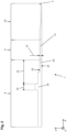
- Figure 1 shows a three-dimensional view of part of a needle-guiding means 3 having a plurality of guiding grooves 4, which are arranged on the base surface 12 of the needle-guiding means 3 and are spaced from each other in peripheral direction U by guiding walls 5.
- a plurality of verge grooves 6, which are offset relative to the guiding grooves 4 in working direction A and peripheral direction U, are arranged on the base surface 12 of the needle-guiding means 3 and are spaced from each other, in peripheral direction U, by verge walls 7.
- An additional bar 21 adjoins every second guiding wall 5 in working direction A.
- the additional bars 21 support a sinker holder 17, which is suitable for guiding sinkers in sinker grooves 20 running in elevational direction H.
- sinker holders 17 are also known as sinker rings on account of their circular shape.
- a plurality of needles 1 is arranged in the guiding grooves 4 and verge grooves 6, with two needles 1 always being arranged together in one guiding groove 4 and each needle 1 always being arranged singly in a verge groove 6.
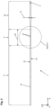
- Figure 2 shows a side view of a needle 1, which has, at its front end pointing in working direction A, a working portion 10 incorporating a loop-building element 2 in the shape of a hook.
- the working portion 10 is suitable to be accommodated in a verge groove 6 of a needle-guiding means 3.
- the needle 1 At its other end, pointing away from the loop-forming element 2, the needle 1 comprises a shank portion 8, which is suitable to be accommodated in a guiding groove 4 of a needle-guiding means 3.
- a bending portion 9 is interposed between the shank portion 8 and the working portion 10.
- the needle height 13 is the height, in elevational direction H, of the needle 1 in the bending portion 9.
- the needle 1 is bounded in peripheral direction U and elevational direction H by the lateral surfaces 23.
- a recess 11 is defined on the lateral surface 23 pointing in peripheral direction U and extends, in working direction A, over the entire length of the bending portion 9 and, in elevational direction H, over the entire needle height 13.
- a drive butt 16 is arranged in the shank portion 8, the distance between the drive butt 16 and the bending portion 9 - i.e. the bending-portion clearance 19 - being greater than the drive-butt length 14.
- Figure 3 shows a top view of the needle 1 of Figure 2 , which is neither plastically nor elastically formed in the bending portion 9.
- the sub-division into a shank portion 8, a bending portion 9 and a working portion 10 corresponds to that of Figure 2 .
- the shank portion 8, the bending portion 9 and the working portion 10 lie exactly on a centerline 15 without any mutual offset in peripheral direction U.
- the needle 1 has a loop-forming element 2 shaped as a hook.
- recesses 11 are defined on both lateral surfaces 23 pointing in peripheral direction U.
- a needle 1 whose bending portion 9 only has a recess 11 defined on one lateral surface 23 pointing in peripheral direction U or elevational direction H is also advantageous for all embodiments of the knitting system.
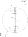
- Figure 3 also indicates the position of the detail A, which is shown enlarged in Figure 4 .
- FIG 4 shows the detail A of Figure 3 .
- Each of the two recesses 11 reduces the width, in peripheral direction U, of the needle 1 in the bending portion 9 - i.e the bending-portion width d B - by the recess depth 22 compared to the shank-portion width d S and the working-portion width d A .
- the recess depth 22 is within the aforementioned selection range. In order to show the recess 11 more clearly, the recess depth 22 is not to scale in the drawing but is enlarged compared to the other components of the needle.
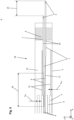
- Figure 5 shows the top view of a section of the base surface 12 of the needle-guiding means 3.
- the needle-guiding means may be a knitting cylinder for circular knitting machines or a needle bed for flat knitting machines.
- the relevant features of Figure 5 may be assigned to both variants of a needle-guiding means 3.
- a plurality of guiding grooves 4 is shown, in one of which two needles 1 are accommodated - i.e. the shank portions 8 of the needles 1 are arranged beside each other in a guiding groove 4.
- the working portions 10 of the two needles 1 are each arranged in a verge groove 6.
- a plurality of guiding grooves 4 is shown, which are spaced from each other by guiding walls 5.
- a plurality of verge grooves 6 is shown as well, which are spaced from each other by verge walls 7. For reasons of clarity, only one guiding groove 4, one verge groove 6, one guiding wall 5 and one verge wall 7 are provided with a reference numeral.
- the lower needle 1 in Figure 5 is shown in an extended state, with the loop-forming element 2 protruding out of the verge groove 6 by the maximum amount.
- the upper of the two needles 1 in Figure 5 is shown in a retracted state, with the loop-forming element 2 protruding out of the verge groove 6 by the minimum amount.
- the needle 1 In the extended state, the needle 1 is displaced relative to its position in the retracted state by the extension length 25 in working direction A.
- the recesses 11 of the lower needle 1 are completely outside of the guiding grooves 4 and the verge grooves 6. As this is the end position during translatory motion in positive working direction A, the recesses 11 do not reach into the verge grooves 6 in any other position either while the needle is moving. In this way, the introduction of dirt into the verge grooves is reduced.
- the recesses 11 of the upper needle 1 are completely outside of the verge grooves 6 and to an extent of two thirds of the recess length 24 outside of the guiding grooves 4.
- FIG. 6 shows enlarged details from Figure 5 .
- a shank offset S exists in peripheral direction U between the respective shank-portion centerline 27 of the shank portion 8 and the working-portion centerline 28 of the working portion 10 of the needles 1.
- the distance between the shank-portion centerlines 27 of adjacent needles 1 corresponds to the shank width d S .
- the pitch t is the distance in peripheral direction between the working-portion centerlines 28 of adjacent needles 1.
- Figure 7 shows a top view of the needle 1, which, in the bending portion 9, is formed in such a way that a shank offset S exists between the working-portion centerline 28 of the working portion 10 and the shank-portion centerline 27 of the shank portion 8.
- the deformation may be a plastic and/or an elastic deformation. Whereas the shank offset S does not change during translatory motion of the needle 1 in working direction A in a needle-guiding means 3, the shape of the deformation is not constant but changes according to the deflection of the needle 1.
- recesses 11 are defined on both the lateral surfaces 23 pointing in peripheral direction U. These recesses 11 reduce the width of the needle 1 in peripheral direction U in the bending portion 9.
- a needle 1 with a recess 11 on only one lateral surface 23 in the bending portion 9 is also advantageous.
- the recess depth 22 of the recesses 11 on the lateral surfaces 23 pointing in peripheral direction U is within the aforementioned selection range of 10 ⁇ m to 100 ⁇ m, more advantageously 30 ⁇ m to 70 ⁇ m.
- the recess depth 22 and the shank offset S are not drawn to scale but are enlarged in order to show them more clearly.
- Figure 8 shows the needle 1 of Figure 5 .
- the shank offset S between the shank-portion centerline 27 and the working-portion centerline 28 is composed of a plastic shank offset S PL and an elastic shank offset S EL .
- the contour of the needle 1 in the state with exclusively plastic deformation (without elastic deformation) is shown here with continuous lines.
- the contour of the needle 1 in the state with plastic deformation and superimposed elastic deformation is shown with broken lines.
- the recess 11 and the shank offset S are not drawn to scale but are enlarged compared to the rest of the drawing in order to show them more clearly.
- Figure 9 shows a side view of a needle 1.
- the needle 1 On its lateral surface 23 pointing in peripheral direction U, the needle 1 has a recess 11 which extends in elevational direction H over less than 80% of the needle height 13.
- the needle 1 On the other lateral surface 23 pointing in peripheral direction U, which is not visible in this drawing, the needle 1 has a second recess 11.
- the recess length 24, in working direction A, of the recess 11 is less than 50% of the length of the bending portion 9 in working direction A. However, it is also advantageous if the recess length 24 is up to 100% or less than 50% of the length of the bending portion 9.
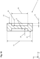
- Figure 10 shows a section in the H-U plane through the needle 1 of Figure 9 at the location of the recesses 11.
- the recess surfaces 29 point in peripheral direction U and each of them is stepped relative to the lateral surfaces 23 pointing in peripheral direction U by the recess depth 22; i.e. each of the recesses 11 reduces the bending-portion width d B in peripheral direction U by the recess depth 22.
- the recess height 26 in elevational direction H is less than 80% of the needle height 13. This feature can be combined advantageously with every embodiment of the knitting system 18 and of the needle 1.
- Figure 11 shows a side view of a needle 1.
- the needle 1 On each of its two lateral surfaces 23 pointing in elevational direction H, the needle 1 has a recess 11 which extends in peripheral direction U over the entire width of the bending portion 9.
- the recess depth 22 of the recesses 11 on the lateral surfaces 23 pointing in elevational direction H is within the aforementioned selection range of 150 ⁇ m to 500 ⁇ m, more advantageously 200 ⁇ m to 400 ⁇ m.
- the recess length 24, in working direction A, of the two recesses 11 is less than 50% of the length of the bending portion 9 in working direction A.
- the recess length 24 is up to 100% or less than 50% of the length of the bending portion 9.
- Figure 12 shows a section in the H-U plane through the needle 1 of Figure 11 at the location of the recesses 11.
- the recesses 11 extend over the entire bending-portion width d B .
- the recess surfaces 29 point in elevational direction H and are stepped relative to the lateral surfaces 23 pointing in elevational direction H by the recess depth 22, so that each of the recesses 11 reduces the cross-section of the bending portion in elevational direction H by the recess depth 22.
Landscapes
- Engineering & Computer Science (AREA)
- Textile Engineering (AREA)
- Knitting Machines (AREA)
Claims (15)
- Nadel (1) mit den folgenden Merkmalen:• einem Maschenbildungselement (2), das an einem in eine positive Arbeitsrichtung (A) weisenden ersten Ende der Nadel (1) angeordnet ist,• einem Schaftbereich (8), der dazu geeignet ist, in einer Führungsnut (4) einer Nadelführungseinrichtung (3) aufgenommen zu werden, und an einem in die negative Arbeitsrichtung (A) weisenden zweiten Ende der Nadel (1) angeordnet ist,• einem Arbeitsbereich (10), der das Maschenbildungselement (2) umfasst, und der dazu geeignet ist, in einer Teilungsnut (6) einer Nadelführungseinrichtung (3) aufgenommen zu werden,• einem Biegebereich (9), der in der Arbeitsrichtung (A) zwischen dem Schaftbereich (8) und dem Arbeitsbereich (10) angeordnet ist• wobei im Biegebereich (9) der Nadel (1) zumindest eine Ausnehmung (11) an zumindest einer ihrer in Umfangsrichtung (U), die senkrecht zur Arbeitsrichtung (A) verläuft, oder in Höhenrichtung (H), die senkrecht zur Arbeitsrichtung (A) und Umfangsrichtung (U) verläuft, weisenden Seitenflächen (23) angeordnet istdadurch gekennzeichnet,dass die zumindest eine Ausnehmung (11) an einer in die Umfangsrichtung (U) weisenden Seitenfläche (23) eine Ausnehmungstiefe (22) von 10 µm bis 100 µm, vorteilhafterweise 30 µm bis 70 µm, aufweist,und/oder dass die zumindest eine Ausnehmung (11) an einer in die Höhenrichtung (H) weisenden Seitenfläche (23) eine Ausnehmungstiefe (22) von 150 µm bis 500 µm, vorteilhafterweise 200 µm bis 400 µm, aufweist.
- Nadel (1) nach einem dem vorstehenden Anspruch
dadurch gekennzeichnet, dass
die zumindest eine Ausnehmung (11) sich in der Höhenrichtung (H) über die gesamte Nadelhöhe (13) erstreckt. - Nadel (1) nach Anspruch 1
dadurch gekennzeichnet, dass
die zumindest eine Ausnehmung (11) sich in der Höhenrichtung (H) über maximal 90% bevorzugterweise maximal 80% der Nadelhöhe (13) erstreckt. - Nadel (1) nach einem der vorstehenden Ansprüche
dadurch gekennzeichnet, dass
der Arbeitsbereich (10) und der Schaftbereich (8) sich im Wesentlichen parallel zueinander in die Arbeitsrichtung (A) erstrecken. - Nadel (1) nach einem der vorstehenden Ansprüche
dadurch gekennzeichnet, dass
der Biegebereich (9) derart plastisch verformt ist, dass in einer Umfangsrichtung (U), die senkrecht zur Arbeitsrichtung (A) verläuft, ein plastischer Schaftversatz (SPL) zwischen dem Arbeitsbereich (10) und dem Schaftbereich (8) besteht. - Stricksystem (18) mit folgenden Merkmalen:• zumindest eine Nadelführungseinrichtung (3), die eine in eine Höhenrichtung (H) weisende Grundfläche (12) aufweist,• zumindest eine Führungsnut (4), die auf der Grundfläche (12) der Nadelführungseinrichtung (3) angeordnet ist und sich im Wesentlichen in einer Arbeitsrichtung (A) erstreckt, wobei die Arbeitsrichtung (A) senkrecht zur Höhenrichtung (H) verläuft,• zumindest eine Teilungsnut (6), die in der Umfangsrichtung (U) und in der Arbeitsrichtung (A) versetzt zu der zumindest einen Führungsnut (4) auf der Grundfläche (12) der Nadelführungseinrichtung (3) angeordnet ist, wobei die Umfangsrichtung (U) senkrecht zu der Arbeitsrichtung (A) und der Höhenrichtung (H) auf der Grundfläche (12) der Nadelführungseinrichtung (3) verläuft,• zumindest eine Nadel (1), die an ihrem in die positive Arbeitsrichtung (A) weisenden ersten Ende einen Arbeitsbereich (10), der ein Maschenbildungselement (2) umfasst, aufweist, und die an ihrem in die negative Arbeitsrichtung (A) weisenden zweiten Ende einen Schaftbereich (8) aufweist,• wobei zwischen dem Schaftbereich (8) und dem Arbeitsbereich (10) ein Biegebereich (9) angeordnet ist, in dem die zumindest eine Nadel (1) eine Biegung mit Richtungsanteilen in der Umfangsrichtung (U) und der Arbeitsrichtung (A) aufweist,• wobei der Arbeitsbereich (10) der zumindest einen Nadel (1) in einer Teilungsnut (6) und der Schaftbereich (8) der zumindest einen Nadel (1) in einer Führungsnut (4) aufgenommen ist,• wobei im Biegebereich (9) der zumindest einen Nadel (1) zumindest eine Ausnehmung (11) an zumindest einer ihrer in die Umfangsrichtung (U) oder in die Höhenrichtung (H) weisenden Seitenflächen (23) angeordnet istdadurch gekennzeichnet,dass die zumindest eine Ausnehmung (11) an einer in die Umfangsrichtung (U) weisenden Seitenfläche (23) eine Ausnehmungstiefe (22) von 10 µm bis 100 µm, vorteilhafterweise 30 µm bis 70 µm, aufweist,und/oder dass die zumindest eine Ausnehmung (11) an einer in die Höhenrichtung (H) weisenden Seitenfläche (23) eine Ausnehmungstiefe (22) von 150 µm bis 500 µm, vorteilhafterweise 200 µm bis 400 µm, aufweist.
- Stricksystem (18) nach dem vorstehenden Anspruch
dadurch gekennzeichnet, dass
die zumindest eine Ausnehmung (11) sich in der Höhenrichtung (H) über die gesamte Nadelhöhe (13) erstreckt. - Stricksystem (18) nach einem der vorstehenden Ansprüche 6 bis 7
dadurch gekennzeichnet, dass
die zumindest eine Ausnehmung (11) der zumindest einen Nadel (1) in einem ausgetriebenen Zustand und/oder einem eingezogenen Zustand vollständig außerhalb der zumindest einen Teilungsnut (6) und/oder der zumindest einen Führungsnut (4) liegt. - Stricksystem (18) nach einem der vorstehenden Ansprüche 6 bis 8
dadurch gekennzeichnet,dass die zumindest eine Ausnehmung (11) der zumindest einen Nadel (1) in dem eingezogenen Zustand zumindest auf einer Länge von 60% bevorzugterweise jedoch 80% der Ausnehmungslänge (24), welche der Erstreckung der Ausnehmung (11) in der Arbeitsrichtung (A) entspricht, außerhalb der zumindest einen Führungsnut (4) liegt,und/oder dass die zumindest eine Ausnehmung (11) der zumindest einen Nadel (1) in dem ausgetriebenen Zustand zumindest auf einer Länge von 60% bevorzugterweise jedoch 80% der Ausnehmungslänge (24) außerhalb der zumindest einen Teilungsnut (6) liegt. - Stricksystem (18) nach einem der vorstehenden Ansprüche 6 bis 9
gekennzeichnet durch• zumindest einen Antriebsfuß (16), der im Schaftbereich (8) der zumindest einen Nadel (1) angeordnet ist, und den umliegenden Schaftbereich (8) in der Höhenrichtung (H) überragt,• und einen Biegebereichsabstand (19), der dem Abstand zwischen dem zumindest einen Antriebsfuß (16) und dem Biegebereich (9) in der Arbeitsrichtung (A) entspricht, wobei der Biegebereichsabstand (19) mindestens so groß ist wie eine Austriebslänge (25), die dem Weg der Nadel (1) in der Arbeitsrichtung (A) zwischen dem eingezogenen Zustand und dem ausgetriebenen Zustand entspricht. - Stricksystem (18) nach einem der vorstehenden Ansprüche 6 bis 10
dadurch gekennzeichnet, dass
der Arbeitsbereich (10) und der Schaftbereich (8) der zumindest einen Nadel (1) sich im Wesentlichen parallel zueinander in die Arbeitsrichtung (A) erstrecken. - Stricksystem (18) nach einem der vorstehenden Ansprüche 6 bis 11
gekennzeichnet durch• zumindest einen Führungssteg (5), der die zumindest eine Führungsnut (4) in der Umfangsrichtung (U) begrenzt,• zumindest einen Hilfssteg (21), der sich in der Arbeitsrichtung (A) an den zumindest einen Führungssteg (5) anschließt und auf der Grundfläche der Nadelführungseinrichtung (3) angeordnet ist, wobei für das Breitenverhältnis (V) der Führungsstegbreite (bFS) zur Hilfsstegbreite (bHS), V=bFS/bHS, gilt:∘ ∘ bevorzugterweise
- Stricksystem (18) nach einem der vorstehenden Ansprüche 6 bis 12
dadurch gekennzeichnet,dass zwischen einer Arbeitsbereichsmittellinie (28), die entlang der Werkzeuglängsrichtung (z) in der Mitte des Arbeitsbereichs (10) verläuft, und einer Schaftbereichsmittellinie (27), die entlang der Werkzeuglängsrichtung (z) in der Mitte des Schaftbereichs (8) verläuft, in der Umfangsrichtung (U) ein Schaftversatz (S) besteht, der sich aus einem plastischen Schaftversatz (SPL) und einem aus einer elastischen Verformung resultierenden elastischen Schaftversatz (SEL) zusammensetzt - also S = SPL + SEL ,und dass, für den Schaftversatz (S) in Abhängigkeit eines Teilungsabstands (t) und der Schaftbreite (dS) der Zusammenhang
- Stricksystem (18) nach einem der vorstehenden Ansprüche 6 bis 13
dadurch gekennzeichnet, dass
die Schaftbereiche (8) von zumindest zwei Nadeln (1) in derselben Führungsnut (4) aufgenommen sind. - Stricksystem (18) nach einem der vorstehenden Ansprüche 6 bis 14
dadurch gekennzeichnet, dass
der Biegebereich (9) der zumindest einen Nadel (1) derart plastisch verformt ist, dass in der Umfangsrichtung (U) ein plastischer Schaftversatz (SPL) zwischen dem Arbeitsbereich (10) und dem Schaftbereich (8) besteht.
Applications Claiming Priority (2)
| Application Number | Priority Date | Filing Date | Title |
|---|---|---|---|
| DE102020128660.0A DE102020128660A1 (de) | 2020-10-30 | 2020-10-30 | Stricksystem und Nadel für Strickmaschinen |
| PCT/EP2021/079909 WO2022090356A1 (en) | 2020-10-30 | 2021-10-28 | Knitting system and needle for knitting machines |
Publications (3)
| Publication Number | Publication Date |
|---|---|
| EP4237606A1 EP4237606A1 (de) | 2023-09-06 |
| EP4237606B1 true EP4237606B1 (de) | 2025-07-02 |
| EP4237606C0 EP4237606C0 (de) | 2025-07-02 |
Family
ID=78500622
Family Applications (1)
| Application Number | Title | Priority Date | Filing Date |
|---|---|---|---|
| EP21801891.9A Active EP4237606B1 (de) | 2020-10-30 | 2021-10-28 | Stricksystem und nadel für strickmaschinen |
Country Status (7)
| Country | Link |
|---|---|
| US (1) | US12553162B2 (de) |
| EP (1) | EP4237606B1 (de) |
| JP (1) | JP2023547648A (de) |
| KR (1) | KR20230093430A (de) |
| CN (1) | CN116547419A (de) |
| DE (1) | DE102020128660A1 (de) |
| WO (1) | WO2022090356A1 (de) |
Families Citing this family (1)
| Publication number | Priority date | Publication date | Assignee | Title |
|---|---|---|---|---|
| WO2024251808A1 (de) * | 2023-06-06 | 2024-12-12 | Groz-Beckert Kg | Strickwerkzeug |
Family Cites Families (18)
| Publication number | Priority date | Publication date | Assignee | Title |
|---|---|---|---|---|
| US664808A (en) * | 1899-12-13 | 1900-12-25 | Dodge Needle Company | Knitting-machine needle. |
| GB315055A (en) * | 1928-05-21 | 1929-07-11 | Thomas Henry Jones | Improvements in or relating to knitting machines |
| DE680319C (de) * | 1935-08-13 | 1939-08-26 | Elite Diamantwerke Akt Ges | Verfahren, Flachstrickmaschine und Nadel zur Herstellung von Strickware mit uebergehaengten Maschen |
| US2240761A (en) * | 1938-10-13 | 1941-05-06 | Hemphill Co | Needle and method of frictioning |
| US2622421A (en) * | 1951-08-06 | 1952-12-23 | May Hosiery Mills | Automatic transfer knitting apparatus |
| CS150732B1 (de) | 1969-12-29 | 1973-09-17 | ||
| DE2851995C2 (de) * | 1978-12-01 | 1980-11-13 | Karl Mayer Textil-Maschinen-Fabrik Gmbh, 6053 Obertshausen | Kettenwirkmaschine mit zwei Nadelbarren |
| DE3921506C1 (de) * | 1989-06-30 | 1990-08-09 | Theodor Groz & Soehne & Ernst Beckert Nadelfabrik Kg, 7470 Albstadt, De | |
| JPH04263658A (ja) * | 1991-02-18 | 1992-09-18 | Fukuhara Seiki Seisakusho:Kk | 編機用編針 |
| IT1284058B1 (it) | 1996-06-21 | 1998-05-08 | Lonati Spa | Uncino per macchine circolari monocilindriche per maglieria o calzetteria con cilindro e platorello o semiplatorello |
| EP1911867B1 (de) | 2006-10-10 | 2017-05-03 | Groz-Beckert KG | Nadelbett mit unterbrochenen Nadelführungen |
| EP2405043A1 (de) * | 2010-07-06 | 2012-01-11 | Groz-Beckert KG | Stricksystem mit abgeflachten Führungskanälen |
| IT1402415B1 (it) | 2010-10-26 | 2013-09-04 | Santoni & C Spa | Macchina per maglieria, particolarmente ad elevata finezza. |
| ITMI20111696A1 (it) * | 2011-09-21 | 2013-03-22 | Santoni & C Spa | Macchina per maglieria, particolarmente ad elevata finezza, con camme di azionamento degli aghi perfezionate. |
| DE102012004150A1 (de) | 2012-02-28 | 2013-08-29 | Bauerfeind Ag | Maschenware mit unterschiedlichen Zonen im Kraft-Dehnungsverhalten |
| PT2927360T (pt) * | 2014-04-03 | 2017-04-20 | Groz Beckert Kg | Ferramenta de tricotar para máquinas de tricotar |
| ITBS20140214A1 (it) * | 2014-12-18 | 2016-06-18 | Santoni & C Spa | Organo porta-aghi per macchina tessile circolare |
| PT3643822T (pt) | 2018-10-23 | 2021-07-26 | Groz Beckert Kg | Dispositivo para a formação de laçada, meios de deslocador e método para a formação de laçada |
-
2020
- 2020-10-30 DE DE102020128660.0A patent/DE102020128660A1/de active Pending
-
2021
- 2021-10-28 KR KR1020237013317A patent/KR20230093430A/ko active Pending
- 2021-10-28 US US18/034,426 patent/US12553162B2/en active Active
- 2021-10-28 CN CN202180073290.0A patent/CN116547419A/zh active Pending
- 2021-10-28 EP EP21801891.9A patent/EP4237606B1/de active Active
- 2021-10-28 WO PCT/EP2021/079909 patent/WO2022090356A1/en not_active Ceased
- 2021-10-28 JP JP2023526397A patent/JP2023547648A/ja active Pending
Also Published As
| Publication number | Publication date |
|---|---|
| DE102020128660A1 (de) | 2022-05-05 |
| US20240352635A1 (en) | 2024-10-24 |
| US12553162B2 (en) | 2026-02-17 |
| WO2022090356A1 (en) | 2022-05-05 |
| TW202223189A (zh) | 2022-06-16 |
| KR20230093430A (ko) | 2023-06-27 |
| EP4237606A1 (de) | 2023-09-06 |
| CN116547419A (zh) | 2023-08-04 |
| JP2023547648A (ja) | 2023-11-13 |
| EP4237606C0 (de) | 2025-07-02 |
Similar Documents
| Publication | Publication Date | Title |
|---|---|---|
| EP2063009B1 (de) | Platine für ein Stricksystem und Stricksystem mit reduziertem Verschleiss | |
| US8438877B2 (en) | Knitting system with flattened guide channels | |
| EP3124664B1 (de) | Maschenbildendes verfahren und vorrichtung | |
| EP2148949B1 (de) | Betriebssichere maschenbildende maschine mit zungennadeln und keinen platinen | |
| EP4237606B1 (de) | Stricksystem und nadel für strickmaschinen | |
| KR100859110B1 (ko) | 편물바늘 및 바늘대 | |
| CN111101288B (zh) | 经编机复合针 | |
| US4041734A (en) | Device for supporting and guiding knitting needles for knitting machines | |
| EP2471984B1 (de) | Flachstrickmaschine | |
| TWI918749B (zh) | 針織機的針織系統及針 | |
| HK40091402A (zh) | 针织系统和用於针织机的针 | |
| EP1860219B1 (de) | Rundstrickmaschine | |
| CN209873257U (zh) | 一种圆筒针织机的压针装置 | |
| EP2392710A1 (de) | Flachstrickmaschine | |
| KR102366041B1 (ko) | 횡편기 | |
| JP2024519163A (ja) | 編み物を製造するためのシンカー、編み装置、および編み方法 | |
| CN112840072B (zh) | 针织机部件以及用于制造针织机部件的方法 | |
| CN116783343A (zh) | 针体、滑动针组件以及经编机 | |
| CN201864891U (zh) | 横机 | |
| HK40048222A (en) | Knitting machine parts and method for production thereof | |
| HK40048222B (en) | Knitting machine parts and method for production thereof | |
| HK40058503B (en) | Knitting machine needle and knitting system | |
| CN101784715A (zh) | 在圆袜机中用于转移线圈的挺针片 |
Legal Events
| Date | Code | Title | Description |
|---|---|---|---|
| STAA | Information on the status of an ep patent application or granted ep patent |
Free format text: STATUS: UNKNOWN |
|
| STAA | Information on the status of an ep patent application or granted ep patent |
Free format text: STATUS: THE INTERNATIONAL PUBLICATION HAS BEEN MADE |
|
| PUAI | Public reference made under article 153(3) epc to a published international application that has entered the european phase |
Free format text: ORIGINAL CODE: 0009012 |
|
| STAA | Information on the status of an ep patent application or granted ep patent |
Free format text: STATUS: REQUEST FOR EXAMINATION WAS MADE |
|
| 17P | Request for examination filed |
Effective date: 20230530 |
|
| AK | Designated contracting states |
Kind code of ref document: A1 Designated state(s): AL AT BE BG CH CY CZ DE DK EE ES FI FR GB GR HR HU IE IS IT LI LT LU LV MC MK MT NL NO PL PT RO RS SE SI SK SM TR |
|
| DAV | Request for validation of the european patent (deleted) | ||
| DAX | Request for extension of the european patent (deleted) | ||
| STAA | Information on the status of an ep patent application or granted ep patent |
Free format text: STATUS: EXAMINATION IS IN PROGRESS |
|
| 17Q | First examination report despatched |
Effective date: 20240313 |
|
| GRAP | Despatch of communication of intention to grant a patent |
Free format text: ORIGINAL CODE: EPIDOSNIGR1 |
|
| STAA | Information on the status of an ep patent application or granted ep patent |
Free format text: STATUS: GRANT OF PATENT IS INTENDED |
|
| INTG | Intention to grant announced |
Effective date: 20250204 |
|
| GRAS | Grant fee paid |
Free format text: ORIGINAL CODE: EPIDOSNIGR3 |
|
| GRAA | (expected) grant |
Free format text: ORIGINAL CODE: 0009210 |
|
| STAA | Information on the status of an ep patent application or granted ep patent |
Free format text: STATUS: THE PATENT HAS BEEN GRANTED |
|
| AK | Designated contracting states |
Kind code of ref document: B1 Designated state(s): AL AT BE BG CH CY CZ DE DK EE ES FI FR GB GR HR HU IE IS IT LI LT LU LV MC MK MT NL NO PL PT RO RS SE SI SK SM TR |
|
| REG | Reference to a national code |
Ref country code: GB Ref legal event code: FG4D |
|
| REG | Reference to a national code |
Ref country code: CH Ref legal event code: EP |
|
| REG | Reference to a national code |
Ref country code: IE Ref legal event code: FG4D |
|
| U01 | Request for unitary effect filed |
Effective date: 20250702 |
|
| U07 | Unitary effect registered |
Designated state(s): AT BE BG DE DK EE FI FR IT LT LU LV MT NL PT RO SE SI Effective date: 20250708 |
|
| U20 | Renewal fee for the european patent with unitary effect paid |
Year of fee payment: 5 Effective date: 20251031 |
|
| PG25 | Lapsed in a contracting state [announced via postgrant information from national office to epo] |
Ref country code: IS Free format text: LAPSE BECAUSE OF FAILURE TO SUBMIT A TRANSLATION OF THE DESCRIPTION OR TO PAY THE FEE WITHIN THE PRESCRIBED TIME-LIMIT Effective date: 20251102 |
|
| PG25 | Lapsed in a contracting state [announced via postgrant information from national office to epo] |
Ref country code: NO Free format text: LAPSE BECAUSE OF FAILURE TO SUBMIT A TRANSLATION OF THE DESCRIPTION OR TO PAY THE FEE WITHIN THE PRESCRIBED TIME-LIMIT Effective date: 20251002 |
|
| PG25 | Lapsed in a contracting state [announced via postgrant information from national office to epo] |
Ref country code: HR Free format text: LAPSE BECAUSE OF FAILURE TO SUBMIT A TRANSLATION OF THE DESCRIPTION OR TO PAY THE FEE WITHIN THE PRESCRIBED TIME-LIMIT Effective date: 20250702 |
|
| PG25 | Lapsed in a contracting state [announced via postgrant information from national office to epo] |
Ref country code: GR Free format text: LAPSE BECAUSE OF FAILURE TO SUBMIT A TRANSLATION OF THE DESCRIPTION OR TO PAY THE FEE WITHIN THE PRESCRIBED TIME-LIMIT Effective date: 20251003 |
|
| PGFP | Annual fee paid to national office [announced via postgrant information from national office to epo] |
Ref country code: TR Payment date: 20251017 Year of fee payment: 5 |
|
| PG25 | Lapsed in a contracting state [announced via postgrant information from national office to epo] |
Ref country code: CZ Free format text: LAPSE BECAUSE OF FAILURE TO SUBMIT A TRANSLATION OF THE DESCRIPTION OR TO PAY THE FEE WITHIN THE PRESCRIBED TIME-LIMIT Effective date: 20250702 |
|
| PG25 | Lapsed in a contracting state [announced via postgrant information from national office to epo] |
Ref country code: PL Free format text: LAPSE BECAUSE OF FAILURE TO SUBMIT A TRANSLATION OF THE DESCRIPTION OR TO PAY THE FEE WITHIN THE PRESCRIBED TIME-LIMIT Effective date: 20250702 |
|
| PG25 | Lapsed in a contracting state [announced via postgrant information from national office to epo] |
Ref country code: RS Free format text: LAPSE BECAUSE OF FAILURE TO SUBMIT A TRANSLATION OF THE DESCRIPTION OR TO PAY THE FEE WITHIN THE PRESCRIBED TIME-LIMIT Effective date: 20251002 |
|
| PG25 | Lapsed in a contracting state [announced via postgrant information from national office to epo] |
Ref country code: ES Free format text: LAPSE BECAUSE OF FAILURE TO SUBMIT A TRANSLATION OF THE DESCRIPTION OR TO PAY THE FEE WITHIN THE PRESCRIBED TIME-LIMIT Effective date: 20250702 |
|
| PG25 | Lapsed in a contracting state [announced via postgrant information from national office to epo] |
Ref country code: SM Free format text: LAPSE BECAUSE OF FAILURE TO SUBMIT A TRANSLATION OF THE DESCRIPTION OR TO PAY THE FEE WITHIN THE PRESCRIBED TIME-LIMIT Effective date: 20250702 |
|
| PG25 | Lapsed in a contracting state [announced via postgrant information from national office to epo] |
Ref country code: SK Free format text: LAPSE BECAUSE OF FAILURE TO SUBMIT A TRANSLATION OF THE DESCRIPTION OR TO PAY THE FEE WITHIN THE PRESCRIBED TIME-LIMIT Effective date: 20250702 |