EP4237308B1 - Anordnung zur übertragung von längskräften bei einem schienenfahrzeug - Google Patents
Anordnung zur übertragung von längskräften bei einem schienenfahrzeug Download PDFInfo
- Publication number
- EP4237308B1 EP4237308B1 EP21819044.5A EP21819044A EP4237308B1 EP 4237308 B1 EP4237308 B1 EP 4237308B1 EP 21819044 A EP21819044 A EP 21819044A EP 4237308 B1 EP4237308 B1 EP 4237308B1
- Authority
- EP
- European Patent Office
- Prior art keywords
- chamber
- link bearing
- axle link
- all1
- all2
- Prior art date
- Legal status (The legal status is an assumption and is not a legal conclusion. Google has not performed a legal analysis and makes no representation as to the accuracy of the status listed.)
- Active
Links
Images
Classifications
-
- B—PERFORMING OPERATIONS; TRANSPORTING
- B61—RAILWAYS
- B61F—RAIL VEHICLE SUSPENSIONS, e.g. UNDERFRAMES, BOGIES OR ARRANGEMENTS OF WHEEL AXLES; RAIL VEHICLES FOR USE ON TRACKS OF DIFFERENT WIDTH; PREVENTING DERAILING OF RAIL VEHICLES; WHEEL GUARDS, OBSTRUCTION REMOVERS OR THE LIKE FOR RAIL VEHICLES
- B61F5/00—Constructional details of bogies; Connections between bogies and vehicle underframes; Arrangements or devices for adjusting or allowing self-adjustment of wheel axles or bogies when rounding curves
- B61F5/38—Arrangements or devices for adjusting or allowing self- adjustment of wheel axles or bogies when rounding curves, e.g. sliding axles, swinging axles
- B61F5/386—Arrangements or devices for adjusting or allowing self- adjustment of wheel axles or bogies when rounding curves, e.g. sliding axles, swinging axles fluid actuated
-
- A—HUMAN NECESSITIES
- A63—SPORTS; GAMES; AMUSEMENTS
- A63B—APPARATUS FOR PHYSICAL TRAINING, GYMNASTICS, SWIMMING, CLIMBING, OR FENCING; BALL GAMES; TRAINING EQUIPMENT
- A63B21/00—Exercising apparatus for developing or strengthening the muscles or joints of the body by working against a counterforce, with or without measuring devices
- A63B21/008—Exercising apparatus for developing or strengthening the muscles or joints of the body by working against a counterforce, with or without measuring devices using hydraulic or pneumatic force-resisters
- A63B21/0083—Exercising apparatus for developing or strengthening the muscles or joints of the body by working against a counterforce, with or without measuring devices using hydraulic or pneumatic force-resisters of the piston-cylinder type
-
- B—PERFORMING OPERATIONS; TRANSPORTING
- B60—VEHICLES IN GENERAL
- B60G—VEHICLE SUSPENSION ARRANGEMENTS
- B60G9/00—Resilient suspensions of a rigid axle or axle housing for two or more wheels
-
- B—PERFORMING OPERATIONS; TRANSPORTING
- B60—VEHICLES IN GENERAL
- B60G—VEHICLE SUSPENSION ARRANGEMENTS
- B60G9/00—Resilient suspensions of a rigid axle or axle housing for two or more wheels
- B60G9/02—Resilient suspensions of a rigid axle or axle housing for two or more wheels the axle or housing being pivotally mounted on the vehicle, e.g. the pivotal axis being parallel to the longitudinal axis of the vehicle
-
- B—PERFORMING OPERATIONS; TRANSPORTING
- B61—RAILWAYS
- B61F—RAIL VEHICLE SUSPENSIONS, e.g. UNDERFRAMES, BOGIES OR ARRANGEMENTS OF WHEEL AXLES; RAIL VEHICLES FOR USE ON TRACKS OF DIFFERENT WIDTH; PREVENTING DERAILING OF RAIL VEHICLES; WHEEL GUARDS, OBSTRUCTION REMOVERS OR THE LIKE FOR RAIL VEHICLES
- B61F5/00—Constructional details of bogies; Connections between bogies and vehicle underframes; Arrangements or devices for adjusting or allowing self-adjustment of wheel axles or bogies when rounding curves
- B61F5/26—Mounting or securing axle-boxes in vehicle or bogie underframes
- B61F5/30—Axle-boxes mounted for movement under spring control in vehicle or bogie underframes
- B61F5/308—Axle-boxes mounted for movement under spring control in vehicle or bogie underframes incorporating damping devices
-
- B—PERFORMING OPERATIONS; TRANSPORTING
- B62—LAND VEHICLES FOR TRAVELLING OTHERWISE THAN ON RAILS
- B62D—MOTOR VEHICLES; TRAILERS
- B62D7/00—Steering linkage; Stub axles or their mountings
- B62D7/06—Steering linkage; Stub axles or their mountings for individually-pivoted wheels, e.g. on king-pins
- B62D7/14—Steering linkage; Stub axles or their mountings for individually-pivoted wheels, e.g. on king-pins the pivotal axes being situated in more than one plane transverse to the longitudinal centre line of the vehicle, e.g. all-wheel steering
- B62D7/142—Steering linkage; Stub axles or their mountings for individually-pivoted wheels, e.g. on king-pins the pivotal axes being situated in more than one plane transverse to the longitudinal centre line of the vehicle, e.g. all-wheel steering specially adapted for particular vehicles, e.g. tractors, carts, earth-moving vehicles, trucks
-
- F—MECHANICAL ENGINEERING; LIGHTING; HEATING; WEAPONS; BLASTING
- F16—ENGINEERING ELEMENTS AND UNITS; GENERAL MEASURES FOR PRODUCING AND MAINTAINING EFFECTIVE FUNCTIONING OF MACHINES OR INSTALLATIONS; THERMAL INSULATION IN GENERAL
- F16F—SPRINGS; SHOCK-ABSORBERS; MEANS FOR DAMPING VIBRATION
- F16F9/00—Springs, vibration-dampers, shock-absorbers, or similarly-constructed movement-dampers using a fluid or the equivalent as damping medium
- F16F9/10—Springs, vibration-dampers, shock-absorbers, or similarly-constructed movement-dampers using a fluid or the equivalent as damping medium using liquid only; using a fluid of which the nature is immaterial
- F16F9/14—Devices with one or more members, e.g. pistons, vanes, moving to and fro in chambers and using throttling effect
- F16F9/145—Devices with one or more members, e.g. pistons, vanes, moving to and fro in chambers and using throttling effect involving only rotary movement of the effective parts
-
- F—MECHANICAL ENGINEERING; LIGHTING; HEATING; WEAPONS; BLASTING
- F16—ENGINEERING ELEMENTS AND UNITS; GENERAL MEASURES FOR PRODUCING AND MAINTAINING EFFECTIVE FUNCTIONING OF MACHINES OR INSTALLATIONS; THERMAL INSULATION IN GENERAL
- F16F—SPRINGS; SHOCK-ABSORBERS; MEANS FOR DAMPING VIBRATION
- F16F9/00—Springs, vibration-dampers, shock-absorbers, or similarly-constructed movement-dampers using a fluid or the equivalent as damping medium
- F16F9/10—Springs, vibration-dampers, shock-absorbers, or similarly-constructed movement-dampers using a fluid or the equivalent as damping medium using liquid only; using a fluid of which the nature is immaterial
- F16F9/14—Devices with one or more members, e.g. pistons, vanes, moving to and fro in chambers and using throttling effect
- F16F9/16—Devices with one or more members, e.g. pistons, vanes, moving to and fro in chambers and using throttling effect involving only straight-line movement of the effective parts
- F16F9/18—Devices with one or more members, e.g. pistons, vanes, moving to and fro in chambers and using throttling effect involving only straight-line movement of the effective parts with a closed cylinder and a piston separating two or more working spaces therein
-
- F—MECHANICAL ENGINEERING; LIGHTING; HEATING; WEAPONS; BLASTING
- F16—ENGINEERING ELEMENTS AND UNITS; GENERAL MEASURES FOR PRODUCING AND MAINTAINING EFFECTIVE FUNCTIONING OF MACHINES OR INSTALLATIONS; THERMAL INSULATION IN GENERAL
- F16H—GEARING
- F16H48/00—Differential gearings
- F16H48/06—Differential gearings with gears having orbital motion
- F16H48/08—Differential gearings with gears having orbital motion comprising bevel gears
Definitions
- the invention relates to an arrangement for transmitting longitudinal forces in a rail vehicle.
- the hydraulic axle guide bearing for a rail vehicle described comprises a guide pin and at least one spring element which is arranged between the guide pin and a guide eye of an axle guide.
- the spring element comprises a hydraulic bushing which has an outer housing and an inner housing.
- the outer housing encloses the inner housing at a radial distance so that an annular gap is formed.
- a (rubber) elastic element is arranged in the annular gap such that it at least partially delimits two diametrically opposed chambers, which are referred to as the first chamber and the second chamber, respectively.
- the two chambers are filled with a hydraulic fluid.
- the two chambers are connected to one another via an internally guided overflow channel.
- the overflow channel achieves a fluid shift between the two chambers, so that a required low longitudinal stiffness is achieved when cornering and a required high stiffness when driving straight or without curves.
- This setting also ensures low-wear and low-noise travel on curved tracks.
- This optimized alignment of the wheelset is made possible by the hydraulic axle guide bearing, which must have the lowest possible longitudinal stiffness when cornering and very high stiffness when traveling straight or without curves.
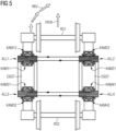
- FIG 5 shows two wheel sets RS1, RS2 of a rail vehicle, which are connected in a known manner to a bogie DGST of a rail vehicle via hydraulic axle guide bearings ALL1 to ALL4.
- the first wheelset RS1 is connected to the bogie DGST via two hydraulic axle guide bearings ALL1 and ALL2, which have external connections and are designed as described above.
- a first axle guide bearing ALL1 has two (diametrically) opposite chambers KAM11, KAM12, which are referred to as the first chamber KAM11 and the second chamber KAM12, respectively.
- the second chamber KAM12 is arranged in front of the first chamber KAM11.
- a second axle guide bearing ALL2 has two (diametrically) opposite chambers KAM21, KAM22, which are referred to as the first chamber KAM21 and the second chamber KAM22, respectively.
- the second chamber KAM22 is arranged in front of the first chamber KAM21.
- the first chamber KAM11 of the first axle guide bearing ALL1 is connected to the first chamber KAM21 of the second axle guide bearing ALL2 for fluid exchange via external connections.
- the second chamber KAM12 of the first axle guide bearing ALL1 is connected to the second chamber KAM22 of the second axle guide bearing ALL2 for fluid exchange via external connections.
- This fluid transfer is caused by a change in the relative position of the housing elements of the axle steering bearings ALL1, ALL2, which in turn is caused by the longitudinal forces.
- the second wheelset RS2 is connected to the bogie DGST via two hydraulic axle guide bearings ALL3 and ALL4, which have external connections and are designed as described above.
- a first axle guide bearing ALL3 has two diametrically opposed chambers KAM31, KAM32, which are referred to as the first chamber KAM31 and the second chamber KAM32, respectively.
- the first chamber KAM31 is arranged in front of the second chamber KAM32.
- a second axle guide bearing ALL4 has two diametrically opposed chambers KAM41, KAM42, which are referred to as the first chamber KAM41 and the second chamber KAM42, respectively.
- the first chamber KAM41 is arranged in front of the second chamber KAM21.
- the first chamber KAM31 of the first axle guide bearing ALL3 is connected to the first chamber KAM41 of the second axle guide bearing ALL4 for fluid exchange via external connections.
- the second chamber KAM32 of the first axle guide bearing ALL3 is connected to the second chamber KAM42 of the second axle guide bearing ALL4 for fluid exchange via external connections.
- the invention relates to an arrangement for transmitting longitudinal forces in a rail vehicle with a first and a second hydraulic axle guide bearing, with a wheelset and with a bogie of the rail vehicle.
- Each axle guide bearing has an outer housing element and an inner housing element as well as a first and a second chamber filled with a fluid.
- the two chambers are arranged opposite each other between the two housing elements, so that a change in the relative position of the inner housing element to the outer housing element causes an alternating change in the volume of the two chambers via a fluid exchange.
- Each axle guide bearing has two external connections, with each chamber of the axle guide bearing being connected to one external connection.
- Each axle guide bearing is connected to both the bogie and the wheelset via the associated housing elements in order to transfer longitudinal forces generated by the rail vehicle during travel between the wheelset and the bogie.
- the longitudinal forces cause the relative position of the inner housing element to change to the outer housing element and thus the alternating volume change of the two chambers due to the exchange of fluid.
- a first chamber of the first axle guide bearing is connected to a first chamber of the second axle guide bearing via a damping element for fluid exchange.
- a second chamber of the first axle guide bearing is directly connected to a second chamber of the second axle guide bearing for fluid exchange.
- the damping element also introduces or influences stiffness into the system.
- the outer housing element of the axle guide bearing encloses the inner housing element at a radial distance, so that an annular gap is formed.
- a (rubber) elastic element is arranged in the annular gap in such a way that it forms the two opposing chambers.
- the first chamber in the axle guide bearing is connected to a first connection via a first channel that runs inside the inner housing element.
- This first connection is arranged as part of the inner housing element in the outer area of the axle guide bearing.
- the second chamber is connected to a second connection via a second channel that runs inside the inner housing element. This second connection is arranged as part of the inner housing element in the outer area of the axle guide bearing.
- the damping element is designed as a cylinder filled with the fluid with an integrated piston.
- the piston is arranged in such a way that the fluid of the first two chambers acting on the piston during the fluid exchange causes a dampened movement of the piston in the cylinder.
- the cylinder has a total cylinder volume which is divided into a first cylinder partial volume and a second cylinder partial volume via the movably mounted piston, so that, depending on the direction of movement of the piston during the fluid exchange, an alternating Volume change of the first cylinder partial volume and the second cylinder partial volume occurs through the piston.
- the first cylinder sub-volume is connected to the first chamber of the first axle guide bearing via an external connection, while the second cylinder sub-volume is connected to the first chamber of the second axle guide bearing via an external connection.
- the stamp is coupled to a spring and a damper connected in parallel to dampen the movement of the stamp.
- the spring and the damper set an intended damping which depends on the position of the stamp and/or its direction of movement.
- the damping element is designed as a possibly adjustable line constriction, through which the movement of the fluid is dampened.
- the present invention transforms unstable eigenmodes of the rail vehicle into stable eigenmodes.
- the present invention enables increased driving speeds to be achieved with high levels of safety.
- the present invention increases the driving stability of the rail vehicle.
- the present invention uses the two lines to ensure that the damping element can be positioned at any location on the rail vehicle.
- the present invention or the damping element connected via external lines makes it possible to advantageously arrange this damping element at a location with sufficiently large installation space and thus, if necessary, also away from the axle guide bearings.
- the individual stiffnesses of the axle guide bearings and the individual dampings of the axle guide bearings as well as the damping in the hydraulic system result in an overall stiffness and an overall damping.
- the present invention achieves suitable or optimal parameter ranges for stiffness and damping.
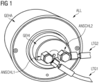
- FIG 1 shows a hydraulic axle guide bearing ALL with external connections ANSCHL1, ANSCHL2, which forms an essential element of the present invention
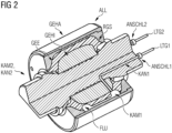
- FIG 2 a cross-sectional view of the FIG 1 shown hydraulic axle guide bearing ALL.
- the axle guide bearing ALL has two external connections ANSCHL1, ANSCHL2, to which the respective connecting lines LTG1, LTG2 are attached.
- the hydraulic axle guide bearing ALL has an outer housing element GEHA and an inner housing element GEHI.
- the outer housing element GEHA encloses the inner housing element GEHI at a radial distance so that an annular gap RGS is formed.
- a (rubber) elastic element GEE is arranged in such a way that it forms two opposing chambers KAM1, KAM2 with respective chamber volumes.
- the two chambers KAM1, KAM2 contain a fluid FLU and can be coupled to chambers of another axle guide bearing via the two external connections ANSCHL1, ANSCHL2 and the respective connecting lines LTG1, LTG2. This is described in FIG 3 described in more detail.
- the first chamber KAM1 is connected to the first connection ANSCHL1 via a first channel KAN1, which runs inside the inner housing element GEHI.
- the first connection ANSCHL1 is part of the inner housing element GEHI and is located in the outer area of the axle guide bearing ALL.
- the second chamber KAM2 is connected to the second connection ANSCHL2 via a second channel KAN2, which also runs inside the inner housing element GEHI.
- the second connection ANSCHL2 is part of the inner housing element GEHI and is located in the outer area of the axle guide bearing ALL.
- the change in the relative position of the two housing elements GEHI, GEHA is caused by longitudinal forces which arise when the rail vehicle is moving and are transmitted from a wheelset to the outer housing element GEHA, from this to the inner housing element GEHI and from this to a bogie of the rail vehicle.
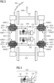
- FIG 3 shows with reference to FIG 1 and FIG 2 the arrangement according to the invention for transmitting longitudinal forces in a rail vehicle.
- the first wheelset RS1 is connected to a bogie DGST of the rail vehicle via two axle guide bearings ALL1, ALL2.
- the wheelset RS1 is connected to an outer housing element GEHA of a first axle guide bearing ALL1 or a second axle guide bearing ALL2. Accordingly, an inner housing element GEHI of the first axle guide bearing ALL1 or the second axle guide bearing ALL2 is connected to the bogie DGST.
- the first axle guide bearing ALL1 has two (diametrically) opposite chambers KAM11, KAM12, which are referred to as the first chamber KAM11 and the second chamber KAM12, respectively.
- the second axle guide bearing ALL2 has two (diametrically) opposite chambers KAM21, KAM22, which are referred to as the first chamber KAM21 and the second chamber KAM22, respectively.
- the two hydraulic axle guide bearings ALL1 and ALL2 each have two external connections to which the respective chambers KAM11, KAM12, KAM21, KAM22 are connected for fluid exchange.
- the second chambers KAM12, KAM22 of the first axle guide bearing ALL1 and the second axle guide bearing ALL2 are arranged in front of the respective first chambers KAM11, KAM21.
- the second chamber KAM12 of the first axle guide bearing ALL1 is directly connected to the second chamber KAM22 of the second axle guide bearing ALL2.
- the first chamber KAM11 of the first axle guide bearing ALL1 is connected to the first chamber KAM21 of the second Axle guide bearing ALL2 is connected via a damping element FDE.
- the second wheelset RS2 is connected to a bogie DGST of the rail vehicle via two axle guide bearings ALL3, ALL4.
- the wheelset RS2 is connected to an outer housing element GEHA of an axle guide bearing designated as the third axle guide bearing ALL3 or of an axle guide bearing designated as the fourth axle guide bearing ALL4. Accordingly, an inner housing element GEHI of the third axle guide bearing ALL3 or the fourth axle guide bearing ALL4 is connected to the bogie DGST.
- the third axle guide bearing ALL3 has two (diametrically) opposite chambers KAM31, KAM32, which are referred to as the first chamber KAM31 and the second chamber KAM32, respectively.
- the fourth axle guide bearing ALL4 has two (diametrically) opposite chambers KAM41, KAM42, which are referred to as the first chamber KAM41 and the second chamber KAM42, respectively.
- the two hydraulic axle guide bearings ALL3 and ALL4 each have two external connections to which the respective chambers KAM31, KAM32, KAM41, KAM42 are connected for fluid exchange.
- the first chambers KAM31, KAM41 of the third axle guide bearing ALL3 and the fourth axle guide bearing ALL4 are arranged in front of the second chambers KAM32, KAM42.
- the second chamber KAM32 of the third axle guide bearing ALL3 is directly connected to the second chamber KAM42 of the fourth axle guide bearing ALL4.
- the first chamber KAM31 of the third axle guide bearing ALL3 is connected to the first chamber KAM41 of the fourth axle guide bearing ALL4 via a damping element FDE.
- FIG 4 shows details of the FIG 3 shown exemplary damping element FDE.
- the damping element FDE is shown here as a cylinder ZYL with an integrated piston STP, whereby the piston STP acts on a spring FD and on a damper DE, which is connected in parallel to the spring FD.
- the cylinder ZYL has a total cylinder volume filled with the fluid FLU, which is divided into a first cylinder partial volume and a second cylinder partial volume via the movably mounted piston STP.
- the spring FD and the damper DE are used to adjust the intended damping depending on the position of the piston or the direction of movement of the piston STP.
- the direction of movement of the piston STP is determined by the direction of movement of the fluid FLU.
- the damping element FDE influences the longitudinal and transverse stiffness of the hydraulic axle guide bearings ALL1 and ALL3 and thus the transmission of the longitudinal forces.
Landscapes
- Engineering & Computer Science (AREA)
- Mechanical Engineering (AREA)
- General Engineering & Computer Science (AREA)
- Health & Medical Sciences (AREA)
- Orthopedic Medicine & Surgery (AREA)
- Transportation (AREA)
- Life Sciences & Earth Sciences (AREA)
- Biophysics (AREA)
- Combustion & Propulsion (AREA)
- General Health & Medical Sciences (AREA)
- Physical Education & Sports Medicine (AREA)
- Chemical & Material Sciences (AREA)
- Combined Devices Of Dampers And Springs (AREA)
- Vehicle Body Suspensions (AREA)
- Support Of The Bearing (AREA)
- Bearings For Parts Moving Linearly (AREA)
Applications Claiming Priority (2)
| Application Number | Priority Date | Filing Date | Title |
|---|---|---|---|
| DE102020216069.4A DE102020216069A1 (de) | 2020-12-16 | 2020-12-16 | Anordnung zur Übertragung von Längskräften bei einem Schienenfahrzeug |
| PCT/EP2021/081992 WO2022128301A1 (de) | 2020-12-16 | 2021-11-17 | Anordnung zur übertragung von längskräften bei einem schienenfahrzeug |
Publications (2)
| Publication Number | Publication Date |
|---|---|
| EP4237308A1 EP4237308A1 (de) | 2023-09-06 |
| EP4237308B1 true EP4237308B1 (de) | 2024-11-06 |
Family
ID=78820272
Family Applications (1)
| Application Number | Title | Priority Date | Filing Date |
|---|---|---|---|
| EP21819044.5A Active EP4237308B1 (de) | 2020-12-16 | 2021-11-17 | Anordnung zur übertragung von längskräften bei einem schienenfahrzeug |
Country Status (7)
| Country | Link |
|---|---|
| US (1) | US20240001973A1 (pl) |
| EP (1) | EP4237308B1 (pl) |
| CN (1) | CN116601021B (pl) |
| DE (1) | DE102020216069A1 (pl) |
| ES (1) | ES3045132T3 (pl) |
| PL (1) | PL4237308T3 (pl) |
| WO (1) | WO2022128301A1 (pl) |
Families Citing this family (1)
| Publication number | Priority date | Publication date | Assignee | Title |
|---|---|---|---|---|
| DE102024208626A1 (de) * | 2024-09-11 | 2026-03-12 | Siemens Mobility GmbH | Hydraulisch angekoppelte Schwingungstilgung |
Family Cites Families (15)
| Publication number | Priority date | Publication date | Assignee | Title |
|---|---|---|---|---|
| DE3123858A1 (de) * | 1981-06-16 | 1982-12-30 | Fried. Krupp Gmbh, 4300 Essen | Laufwerk fuer ein schienenfahrzeug |
| DE3331559A1 (de) * | 1983-09-01 | 1985-03-28 | Thyssen Industrie Ag, 4300 Essen | Achssteuerung fuer schienenfahrzeuge |
| JPS63231032A (ja) * | 1987-03-16 | 1988-09-27 | Toyota Motor Corp | 流体入りブツシユ |
| AT407140B (de) * | 1993-11-26 | 2000-12-27 | Integral Verkehrstechnik Ag | Einrichtung zur steuerung eines rades, insbesondere eines radsatzes eines schienenfahrzeuges |
| ES2228090T3 (es) | 1999-08-31 | 2005-04-01 | Construcciones Y Auxiliar De Ferrocarriles S.A. Caf. | Dispositivo de guiado de los ejes de un vehiculo ferroviario. |
| DE10310634A1 (de) | 2003-03-10 | 2004-09-30 | Carl Freudenberg Kg | Achslenkerlager |
| DE102010033811B4 (de) | 2010-08-09 | 2020-03-05 | Gmt Gummi-Metall-Technik Gmbh | Hydraulisch dämpfende Hydro-Lager für Achslenkerlager |
| BR112013010711A2 (pt) * | 2010-11-01 | 2019-09-24 | Rsd A Division Of Dcd Dorbyl Pty Ltd | truque de ferrovia autodirigível |
| ES2750362T3 (es) | 2013-01-30 | 2020-03-25 | Bombardier Transp Gmbh | Tren de rodaje con unidad de rueda dirigida |
| DE102013103827A1 (de) | 2013-04-16 | 2014-10-16 | Bombardier Transportation Gmbh | Fahrwerk mit quergekoppelten Radeinheiten |
| DE102014003506A1 (de) | 2014-03-14 | 2015-09-17 | Carl Freudenberg Kg | Hydrobuchsenanordnung |
| DE102014214055A1 (de) * | 2014-07-18 | 2016-01-21 | Siemens Aktiengesellschaft | Fahrwerk für ein Schienenfahrzeug |
| GB2542639A (en) * | 2015-09-28 | 2017-03-29 | Bombardier Transp Gmbh | Running gear provided with a passive hydraulic wheel set steering system for a rail vehicle |
| CN106828528A (zh) * | 2017-01-03 | 2017-06-13 | 株洲九方装备股份有限公司 | 一种城际轨道车辆车身抗折弯控制方法及装置 |
| CN111232008B (zh) * | 2020-03-09 | 2024-10-22 | 西南交通大学 | 铁道车辆转向架自导向径向机构 |
-
2020
- 2020-12-16 DE DE102020216069.4A patent/DE102020216069A1/de not_active Withdrawn
-
2021
- 2021-11-17 ES ES21819044T patent/ES3045132T3/es active Active
- 2021-11-17 EP EP21819044.5A patent/EP4237308B1/de active Active
- 2021-11-17 PL PL21819044.5T patent/PL4237308T3/pl unknown
- 2021-11-17 WO PCT/EP2021/081992 patent/WO2022128301A1/de not_active Ceased
- 2021-11-17 CN CN202180084082.0A patent/CN116601021B/zh active Active
- 2021-11-17 US US18/257,994 patent/US20240001973A1/en active Pending
Also Published As
| Publication number | Publication date |
|---|---|
| CN116601021B (zh) | 2026-03-27 |
| CN116601021A (zh) | 2023-08-15 |
| PL4237308T3 (pl) | 2025-03-03 |
| EP4237308A1 (de) | 2023-09-06 |
| WO2022128301A1 (de) | 2022-06-23 |
| US20240001973A1 (en) | 2024-01-04 |
| ES3045132T3 (en) | 2025-11-27 |
| DE102020216069A1 (de) | 2022-06-23 |
Similar Documents
| Publication | Publication Date | Title |
|---|---|---|
| DE69931859T2 (de) | Fahrzeugaufhängungsvorrichtung | |
| DE60013732T2 (de) | Radaufhängungssystem für ein Fahrzeug | |
| DE69101803T2 (de) | Verbesserungen zu hydraulischen Antischwingungsbuchsen. | |
| DE102017218905B4 (de) | Feder-Dämpfersystem mit variabler Federrate | |
| DE69920527T2 (de) | Vorrichtung zur steuerung der achsen eines schienenfahrzeuges | |
| EP4081414B1 (de) | Ansteuervorrichtung | |
| EP3046824A1 (de) | Fahrwerk für ein schienenfahrzeug | |
| DE10035024A1 (de) | Hydraulisch dämpfendes Elastomerlager | |
| EP2986482A1 (de) | Fahrwerk mit quergekoppelten radeinheiten | |
| EP4237308B1 (de) | Anordnung zur übertragung von längskräften bei einem schienenfahrzeug | |
| EP4237307B1 (de) | Anordnung zur übertragung von längskräften bei einem schienenfahrzeug | |
| EP3384178B1 (de) | Hydraulische lagerbuchse | |
| EP2065286A1 (de) | Schienenfahrzeug sowie Verfahren zur Kopplung von Drehgestellen eines Schienenfahrzeuges | |
| EP2353961A1 (de) | Fahrwerk für ein Schienenfahrzeug | |
| DE102023107421A1 (de) | Dämpfungssystem und Kraftfahrzeug | |
| AT524029B1 (de) | Elastikelement und Fahrwerk | |
| DE102008045537A1 (de) | Servoventil | |
| DE102009020249A1 (de) | Anordnung zur Fahrwerksstabilisierung | |
| DE102018206940B4 (de) | Verbund-Blattfeder mit hydraulischem Buchsenelement | |
| EP0755839A2 (de) | Spurgeführtes Fahrzeug, insbesondere Schienenfahrzeug für den Nahverkehr | |
| EP0644105B1 (de) | Vorrichtung zur Steuerung der Knickbewegungen zwischen Teilfahrzeugen von Gelenkomnibussen | |
| EP3816010B1 (de) | Elastikelement | |
| EP1074449A1 (de) | Spurgeführtes Fahrzeug, insbesondere Schienenfahrzeug für den Nahverkehr | |
| EP4299947A1 (de) | Fluidische koppelvorrichtung und fahrwerk | |
| EP4227188A1 (de) | Schienenfahrzeugfahrwerk mit einer vorrichtung zum steuern einer radachse |
Legal Events
| Date | Code | Title | Description |
|---|---|---|---|
| STAA | Information on the status of an ep patent application or granted ep patent |
Free format text: STATUS: UNKNOWN |
|
| STAA | Information on the status of an ep patent application or granted ep patent |
Free format text: STATUS: THE INTERNATIONAL PUBLICATION HAS BEEN MADE |
|
| PUAI | Public reference made under article 153(3) epc to a published international application that has entered the european phase |
Free format text: ORIGINAL CODE: 0009012 |
|
| STAA | Information on the status of an ep patent application or granted ep patent |
Free format text: STATUS: REQUEST FOR EXAMINATION WAS MADE |
|
| 17P | Request for examination filed |
Effective date: 20230601 |
|
| AK | Designated contracting states |
Kind code of ref document: A1 Designated state(s): AL AT BE BG CH CY CZ DE DK EE ES FI FR GB GR HR HU IE IS IT LI LT LU LV MC MK MT NL NO PL PT RO RS SE SI SK SM TR |
|
| DAV | Request for validation of the european patent (deleted) | ||
| DAX | Request for extension of the european patent (deleted) | ||
| GRAP | Despatch of communication of intention to grant a patent |
Free format text: ORIGINAL CODE: EPIDOSNIGR1 |
|
| STAA | Information on the status of an ep patent application or granted ep patent |
Free format text: STATUS: GRANT OF PATENT IS INTENDED |
|
| INTG | Intention to grant announced |
Effective date: 20240708 |
|
| GRAS | Grant fee paid |
Free format text: ORIGINAL CODE: EPIDOSNIGR3 |
|
| GRAA | (expected) grant |
Free format text: ORIGINAL CODE: 0009210 |
|
| STAA | Information on the status of an ep patent application or granted ep patent |
Free format text: STATUS: THE PATENT HAS BEEN GRANTED |
|
| AK | Designated contracting states |
Kind code of ref document: B1 Designated state(s): AL AT BE BG CH CY CZ DE DK EE ES FI FR GB GR HR HU IE IS IT LI LT LU LV MC MK MT NL NO PL PT RO RS SE SI SK SM TR |
|
| REG | Reference to a national code |
Ref country code: GB Ref legal event code: FG4D Free format text: NOT ENGLISH |
|
| REG | Reference to a national code |
Ref country code: CH Ref legal event code: EP |
|
| REG | Reference to a national code |
Ref country code: DE Ref legal event code: R096 Ref document number: 502021005761 Country of ref document: DE |
|
| REG | Reference to a national code |
Ref country code: IE Ref legal event code: FG4D Free format text: LANGUAGE OF EP DOCUMENT: GERMAN |
|
| REG | Reference to a national code |
Ref country code: LT Ref legal event code: MG9D |
|
| REG | Reference to a national code |
Ref country code: NL Ref legal event code: MP Effective date: 20241106 |
|
| PG25 | Lapsed in a contracting state [announced via postgrant information from national office to epo] |
Ref country code: IS Free format text: LAPSE BECAUSE OF FAILURE TO SUBMIT A TRANSLATION OF THE DESCRIPTION OR TO PAY THE FEE WITHIN THE PRESCRIBED TIME-LIMIT Effective date: 20250306 Ref country code: HR Free format text: LAPSE BECAUSE OF FAILURE TO SUBMIT A TRANSLATION OF THE DESCRIPTION OR TO PAY THE FEE WITHIN THE PRESCRIBED TIME-LIMIT Effective date: 20241106 Ref country code: PT Free format text: LAPSE BECAUSE OF FAILURE TO SUBMIT A TRANSLATION OF THE DESCRIPTION OR TO PAY THE FEE WITHIN THE PRESCRIBED TIME-LIMIT Effective date: 20250306 |
|
| PGFP | Annual fee paid to national office [announced via postgrant information from national office to epo] |
Ref country code: DE Payment date: 20250120 Year of fee payment: 4 |
|
| PG25 | Lapsed in a contracting state [announced via postgrant information from national office to epo] |
Ref country code: FI Free format text: LAPSE BECAUSE OF FAILURE TO SUBMIT A TRANSLATION OF THE DESCRIPTION OR TO PAY THE FEE WITHIN THE PRESCRIBED TIME-LIMIT Effective date: 20241106 Ref country code: NL Free format text: LAPSE BECAUSE OF FAILURE TO SUBMIT A TRANSLATION OF THE DESCRIPTION OR TO PAY THE FEE WITHIN THE PRESCRIBED TIME-LIMIT Effective date: 20241106 |
|
| PG25 | Lapsed in a contracting state [announced via postgrant information from national office to epo] |
Ref country code: BG Free format text: LAPSE BECAUSE OF FAILURE TO SUBMIT A TRANSLATION OF THE DESCRIPTION OR TO PAY THE FEE WITHIN THE PRESCRIBED TIME-LIMIT Effective date: 20241106 |
|
| PGFP | Annual fee paid to national office [announced via postgrant information from national office to epo] |
Ref country code: ES Payment date: 20250227 Year of fee payment: 4 |
|
| PG25 | Lapsed in a contracting state [announced via postgrant information from national office to epo] |
Ref country code: NO Free format text: LAPSE BECAUSE OF FAILURE TO SUBMIT A TRANSLATION OF THE DESCRIPTION OR TO PAY THE FEE WITHIN THE PRESCRIBED TIME-LIMIT Effective date: 20250206 |
|
| PG25 | Lapsed in a contracting state [announced via postgrant information from national office to epo] |
Ref country code: GR Free format text: LAPSE BECAUSE OF FAILURE TO SUBMIT A TRANSLATION OF THE DESCRIPTION OR TO PAY THE FEE WITHIN THE PRESCRIBED TIME-LIMIT Effective date: 20250207 Ref country code: LV Free format text: LAPSE BECAUSE OF FAILURE TO SUBMIT A TRANSLATION OF THE DESCRIPTION OR TO PAY THE FEE WITHIN THE PRESCRIBED TIME-LIMIT Effective date: 20241106 |
|
| PGFP | Annual fee paid to national office [announced via postgrant information from national office to epo] |
Ref country code: CH Payment date: 20250210 Year of fee payment: 4 |
|
| PG25 | Lapsed in a contracting state [announced via postgrant information from national office to epo] |
Ref country code: IT Free format text: LAPSE BECAUSE OF NON-PAYMENT OF DUE FEES Effective date: 20241117 |
|
| PG25 | Lapsed in a contracting state [announced via postgrant information from national office to epo] |
Ref country code: RS Free format text: LAPSE BECAUSE OF FAILURE TO SUBMIT A TRANSLATION OF THE DESCRIPTION OR TO PAY THE FEE WITHIN THE PRESCRIBED TIME-LIMIT Effective date: 20250206 |
|
| PG25 | Lapsed in a contracting state [announced via postgrant information from national office to epo] |
Ref country code: SM Free format text: LAPSE BECAUSE OF FAILURE TO SUBMIT A TRANSLATION OF THE DESCRIPTION OR TO PAY THE FEE WITHIN THE PRESCRIBED TIME-LIMIT Effective date: 20241106 |
|
| PG25 | Lapsed in a contracting state [announced via postgrant information from national office to epo] |
Ref country code: DK Free format text: LAPSE BECAUSE OF FAILURE TO SUBMIT A TRANSLATION OF THE DESCRIPTION OR TO PAY THE FEE WITHIN THE PRESCRIBED TIME-LIMIT Effective date: 20241106 |
|
| PG25 | Lapsed in a contracting state [announced via postgrant information from national office to epo] |
Ref country code: LU Free format text: LAPSE BECAUSE OF NON-PAYMENT OF DUE FEES Effective date: 20241117 |
|
| PG25 | Lapsed in a contracting state [announced via postgrant information from national office to epo] |
Ref country code: EE Free format text: LAPSE BECAUSE OF FAILURE TO SUBMIT A TRANSLATION OF THE DESCRIPTION OR TO PAY THE FEE WITHIN THE PRESCRIBED TIME-LIMIT Effective date: 20241106 |
|
| PG25 | Lapsed in a contracting state [announced via postgrant information from national office to epo] |
Ref country code: RO Free format text: LAPSE BECAUSE OF FAILURE TO SUBMIT A TRANSLATION OF THE DESCRIPTION OR TO PAY THE FEE WITHIN THE PRESCRIBED TIME-LIMIT Effective date: 20241106 |
|
| PG25 | Lapsed in a contracting state [announced via postgrant information from national office to epo] |
Ref country code: SK Free format text: LAPSE BECAUSE OF FAILURE TO SUBMIT A TRANSLATION OF THE DESCRIPTION OR TO PAY THE FEE WITHIN THE PRESCRIBED TIME-LIMIT Effective date: 20241106 |
|
| REG | Reference to a national code |
Ref country code: DE Ref legal event code: R097 Ref document number: 502021005761 Country of ref document: DE |
|
| REG | Reference to a national code |
Ref country code: DE Ref legal event code: R081 Ref document number: 502021005761 Country of ref document: DE Owner name: SIEMENS MOBILITY GMBH, DE Free format text: FORMER OWNER: SIEMENS MOBILITY GMBH, 81739 MUENCHEN, DE |
|
| REG | Reference to a national code |
Ref country code: BE Ref legal event code: MM Effective date: 20241130 |
|
| PG25 | Lapsed in a contracting state [announced via postgrant information from national office to epo] |
Ref country code: SE Free format text: LAPSE BECAUSE OF FAILURE TO SUBMIT A TRANSLATION OF THE DESCRIPTION OR TO PAY THE FEE WITHIN THE PRESCRIBED TIME-LIMIT Effective date: 20241106 |
|
| PLBE | No opposition filed within time limit |
Free format text: ORIGINAL CODE: 0009261 |
|
| STAA | Information on the status of an ep patent application or granted ep patent |
Free format text: STATUS: NO OPPOSITION FILED WITHIN TIME LIMIT |
|
| PG25 | Lapsed in a contracting state [announced via postgrant information from national office to epo] |
Ref country code: MC Free format text: LAPSE BECAUSE OF FAILURE TO SUBMIT A TRANSLATION OF THE DESCRIPTION OR TO PAY THE FEE WITHIN THE PRESCRIBED TIME-LIMIT Effective date: 20241106 |
|
| 26N | No opposition filed |
Effective date: 20250807 |
|
| PG25 | Lapsed in a contracting state [announced via postgrant information from national office to epo] |
Ref country code: BE Free format text: LAPSE BECAUSE OF NON-PAYMENT OF DUE FEES Effective date: 20241130 |
|
| PG25 | Lapsed in a contracting state [announced via postgrant information from national office to epo] |
Ref country code: IE Free format text: LAPSE BECAUSE OF NON-PAYMENT OF DUE FEES Effective date: 20241117 |
|
| REG | Reference to a national code |
Ref country code: ES Ref legal event code: FG2A Ref document number: 3045132 Country of ref document: ES Kind code of ref document: T3 Effective date: 20251127 |
|
| PGFP | Annual fee paid to national office [announced via postgrant information from national office to epo] |
Ref country code: AT Payment date: 20260113 Year of fee payment: 5 |
|
| PG25 | Lapsed in a contracting state [announced via postgrant information from national office to epo] |
Ref country code: IT Free format text: LAPSE BECAUSE OF NON-PAYMENT OF DUE FEES Effective date: 20241117 |
|
| PGFP | Annual fee paid to national office [announced via postgrant information from national office to epo] |
Ref country code: IT Payment date: 20251125 Year of fee payment: 5 |
|
| PGRI | Patent reinstated in contracting state [announced from national office to epo] |
Ref country code: IT Effective date: 20241130 |
|
| PGFP | Annual fee paid to national office [announced via postgrant information from national office to epo] |
Ref country code: FR Payment date: 20251114 Year of fee payment: 5 |
|
| PGFP | Annual fee paid to national office [announced via postgrant information from national office to epo] |
Ref country code: CZ Payment date: 20251111 Year of fee payment: 5 |
|
| PGFP | Annual fee paid to national office [announced via postgrant information from national office to epo] |
Ref country code: PL Payment date: 20251106 Year of fee payment: 5 |
|
| REG | Reference to a national code |
Ref country code: CH Ref legal event code: U11 Free format text: ST27 STATUS EVENT CODE: U-0-0-U10-U11 (AS PROVIDED BY THE NATIONAL OFFICE) Effective date: 20260209 |
|
| PG25 | Lapsed in a contracting state [announced via postgrant information from national office to epo] |
Ref country code: HU Free format text: LAPSE BECAUSE OF FAILURE TO SUBMIT A TRANSLATION OF THE DESCRIPTION OR TO PAY THE FEE WITHIN THE PRESCRIBED TIME-LIMIT; INVALID AB INITIO Effective date: 20211117 |