EP4234332B1 - Zusammenklappbare fahrzeugkameraarmanordnung - Google Patents
Zusammenklappbare fahrzeugkameraarmanordnung Download PDFInfo
- Publication number
- EP4234332B1 EP4234332B1 EP23157350.2A EP23157350A EP4234332B1 EP 4234332 B1 EP4234332 B1 EP 4234332B1 EP 23157350 A EP23157350 A EP 23157350A EP 4234332 B1 EP4234332 B1 EP 4234332B1
- Authority
- EP
- European Patent Office
- Prior art keywords
- detent
- detent ring
- projections
- carrier base
- support arm
- Prior art date
- Legal status (The legal status is an assumption and is not a legal conclusion. Google has not performed a legal analysis and makes no representation as to the accuracy of the status listed.)
- Active
Links
Images





Classifications
-
- B—PERFORMING OPERATIONS; TRANSPORTING
- B60—VEHICLES IN GENERAL
- B60R—VEHICLES, VEHICLE FITTINGS, OR VEHICLE PARTS, NOT OTHERWISE PROVIDED FOR
- B60R1/00—Optical viewing arrangements; Real-time viewing arrangements for drivers or passengers using optical image capturing systems, e.g. cameras or video systems specially adapted for use in or on vehicles
- B60R1/02—Rear-view mirror arrangements
- B60R1/06—Rear-view mirror arrangements mounted on vehicle exterior
- B60R1/0605—Rear-view mirror arrangements mounted on vehicle exterior specially adapted for mounting on trucks, e.g. by C-shaped support means
- B60R1/0617—Rear-view mirror arrangements mounted on vehicle exterior specially adapted for mounting on trucks, e.g. by C-shaped support means foldable along the vehicle, e.g. in case of external force applied thereon
-
- B—PERFORMING OPERATIONS; TRANSPORTING
- B60—VEHICLES IN GENERAL
- B60R—VEHICLES, VEHICLE FITTINGS, OR VEHICLE PARTS, NOT OTHERWISE PROVIDED FOR
- B60R11/00—Arrangements for holding or mounting articles, not otherwise provided for
- B60R11/04—Mounting of cameras operative during drive; Arrangement of controls thereof relative to the vehicle
-
- B—PERFORMING OPERATIONS; TRANSPORTING
- B60—VEHICLES IN GENERAL
- B60R—VEHICLES, VEHICLE FITTINGS, OR VEHICLE PARTS, NOT OTHERWISE PROVIDED FOR
- B60R1/00—Optical viewing arrangements; Real-time viewing arrangements for drivers or passengers using optical image capturing systems, e.g. cameras or video systems specially adapted for use in or on vehicles
- B60R1/20—Real-time viewing arrangements for drivers or passengers using optical image capturing systems, e.g. cameras or video systems specially adapted for use in or on vehicles
- B60R1/22—Real-time viewing arrangements for drivers or passengers using optical image capturing systems, e.g. cameras or video systems specially adapted for use in or on vehicles for viewing an area outside the vehicle, e.g. the exterior of the vehicle
- B60R1/23—Real-time viewing arrangements for drivers or passengers using optical image capturing systems, e.g. cameras or video systems specially adapted for use in or on vehicles for viewing an area outside the vehicle, e.g. the exterior of the vehicle with a predetermined field of view
- B60R1/25—Real-time viewing arrangements for drivers or passengers using optical image capturing systems, e.g. cameras or video systems specially adapted for use in or on vehicles for viewing an area outside the vehicle, e.g. the exterior of the vehicle with a predetermined field of view to the sides of the vehicle
-
- G—PHYSICS
- G03—PHOTOGRAPHY; CINEMATOGRAPHY; ANALOGOUS TECHNIQUES USING WAVES OTHER THAN OPTICAL WAVES; ELECTROGRAPHY; HOLOGRAPHY
- G03B—APPARATUS OR ARRANGEMENTS FOR TAKING PHOTOGRAPHS OR FOR PROJECTING OR VIEWING THEM; APPARATUS OR ARRANGEMENTS EMPLOYING ANALOGOUS TECHNIQUES USING WAVES OTHER THAN OPTICAL WAVES; ACCESSORIES THEREFOR
- G03B17/00—Details of cameras or camera bodies; Accessories therefor
- G03B17/56—Accessories
- G03B17/561—Support related camera accessories
-
- B—PERFORMING OPERATIONS; TRANSPORTING
- B60—VEHICLES IN GENERAL
- B60R—VEHICLES, VEHICLE FITTINGS, OR VEHICLE PARTS, NOT OTHERWISE PROVIDED FOR
- B60R11/00—Arrangements for holding or mounting articles, not otherwise provided for
- B60R2011/0001—Arrangements for holding or mounting articles, not otherwise provided for characterised by position
- B60R2011/004—Arrangements for holding or mounting articles, not otherwise provided for characterised by position outside the vehicle
-
- B—PERFORMING OPERATIONS; TRANSPORTING
- B60—VEHICLES IN GENERAL
- B60R—VEHICLES, VEHICLE FITTINGS, OR VEHICLE PARTS, NOT OTHERWISE PROVIDED FOR
- B60R11/00—Arrangements for holding or mounting articles, not otherwise provided for
- B60R2011/0042—Arrangements for holding or mounting articles, not otherwise provided for characterised by mounting means
- B60R2011/008—Adjustable or movable supports
- B60R2011/0082—Adjustable or movable supports collapsible, e.g. for storing after use
Definitions
- This application relates to camera mirror arm assembly, and more particularly, to a foldable camera mirror assembly for use in a commercial truck, for example.
- Foldable camera mirror assemblies can be motorized or manually operated.
- a drive motor must be located in a portion of assembly and are usually located adjacent a pivotable joint between a vehicle fixed housing and a pivotable housing.
- manually operated foldable camera mirror systems do not include a drive motor and are generally pivoted by a user of the vehicle to place the assembly in a desired position.
- the vehicle arm assembly includes a carrier base for attaching to a vehicle.
- a support arm is rotatably mounted relative to the carrier base.
- a first detent ring includes a plurality of first detent projections circumferentially offset by a plurality of first detent channels.
- a second detent ring includes a plurality of second detent projections circumferentially offset by a plurality of second detent channels. The first detent ring is fixed relative to one of the carrier base or the support arm. The second detent ring is fixed relative to the other of the carrier base or the support ring.
- the first detent ring is in an intermeshing arrangement when the second detent ring in a first rotational position and in a non-intermeshing arrangement when in a second rotational position.
- a first stop surface fixed relative to the carrier base is in engagement with a stop fixed relative to the support arm.
- the plurality of first projections include at least two first projections each extending a first arcuate distance around the first detent ring.
- a single first projection extends a second arcuate distance around the first detent ring. The second arcuate distance is greater than the first arcuate distance.
- the single one of the plurality of first detent projection and one of the at least two first projections together extend an arcuate distance of at least 60 degrees and less than 120 degrees around the first detent ring.
- the plurality of second detent channels may include a first set of second channels that extend for a first arcuate length.
- a single second channel may extend a third arcuate distance.
- the third arcuate distance may be greater than the first arcuate distance.
- the third arcuate distance may be greater than second arcuate distance.
- the one of the at least two first projections and the single first projection may be configured to intermesh with the single second channel.
- the second single channel may extend an arcuate distance of at least 60 degrees around the second detent ring.
- the second single channel may extend an arcuate distance of less than 120 degrees around the second detent ring.
- the second single channel may extend an arcuate distance of at least 60 degrees and less than 120 degrees around the second detent ring.
- the second single channel may extend an arcuate distance of at least 75 degrees around the second detent ring.
- the second single channel may extend an arcuate distance of less than 105 degrees around the second detent ring.
- the second single channel may extend an arcuate distance of at least 75 degrees and less than 105 degrees around the second detent ring.
- the second detent ring may include a radially inner wall and a radially outer wall that creates recessed area for the plurality of second projections and the plurality of second channels.
- Each of the plurality of first channels may include an axially outer surface and each of the plurality of first projections may include an axially outer surface.
- the planar surface of each of the plurality of first channels may be connected to an adjacent one of the plurality of first projections by a connecting planar surface that is transverse to the channel planar surface and the projection planar surface.
- the first detent ring may be integrally formed as a unitary piece with the one of the carrier base or the support arm.
- the second detent ring may be integrally formed as a unitary piece with the other of the carrier base or the support arm.
- the first detent ring may be separately formed and connected, mounted, fixed etc. (permanently or removably) to or with the one of the carrier base or the support arm.
- the second detent ring may be separately formed and connected, mounted, fixed (permanently or removably) to or with the other of the carrier base or the support arm.
- the first detent ring may be removably attached to one of the carrier base or the support arm.
- the second detent ring may be removably attached to the other of the carrier base or the support arm.
- At least one camera may be fixed relative to the support arm.
- a method of operating a vehicle arm assembly includes rotating a support arm including one of a first detent ring or a second detent ring relative to a carrier base having the other of the first detent ring or the second detent ring.
- the first detent ring is configured to intermesh with the second detent ring.
- Rotation of the support arm is limited relative to the carrier base in a first rotational direction with a first stop surface fixed relative to the carrier base engaging a stop fixed relative to the support arm.
- the first detent ring and the second detent ring are in a non-intermeshed relationship when the stop engages the first stop surface.
- the first detent ring may include a plurality of first channels separating a plurality of first projections.
- the plurality of first projections may include at least two first projections each extending a first arcuate distance around the first detent ring.
- a single first projection may extend a second arcuate distance around the first detent ring. The second arcuate distance may be greater than the first arcuate distance.
- the single first projection, one of the first channels, and one of the at least two first projections may extend an arcuate distance of at least 60 degrees around the first detent ring.
- the single first projection, one of the first channels, and one of the at least two first projections may extend an arcuate distance of less than 120 degrees around the first detent ring.
- the single first projection, one of the first channels, and one of the at least two first projections may extend an arcuate distance of at least 60 degrees and less than 120 degrees around the first detent ring.
- the second detent ring may include a plurality of second detent channels have a first set of second detent channels that extend for the first arcuate distance.
- a single second detent channel may extend a third arcuate distance.
- the third arcuate distance may be greater than the first arcuate distance.
- the single second detent channel may extend an arcuate distance of at least 60 degrees around the second detent ring.
- the single second detent channel may extend an arcuate distance of less than 120 degrees around the second detent ring.
- the single second detent channel may extend an arcuate distance of at least 60 degrees and less than 120 degrees around the second detent ring.
- the single second detent channel may extend an arcuate distance of at least 75 degrees around the second detent ring.
- the single second detent channel may extend an arcuate distance of less than 105 degrees around the second detent ring.
- the single second detent channel may extend an arcuate distance of at least 75 degrees and less than 105 degrees around the second detent ring.
- the method may comprise limiting rotation of the support arm relative to the carrier base in a second rotational direction with a second stop surface fixed relative to the carrier base engaging the stop fixed relative to the support arm.
- the first detent ring and the second detent ring may be in a non-intermeshing relationship when the stop engages the second stop surface.
- FIG. 1 A schematic view of a commercial vehicle 10 is illustrated in Figure 1 .
- the vehicle 10 includes a vehicle cab 12 for towing a trailer 14.
- Driver and passenger side arm assemblies 16 are mounted to the vehicle cab 12, such as a camera arm assembly. If desired, the arm assemblies 16 may include conventional mirrors integrated with them as well.
- First and second displays 18 are arranged on each of the driver and passenger sides within the vehicle cab 12 near the A-pillars to display Class II and Class IV views on each side of the vehicle 10.
- a rearward facing camera 20 is arranged within each arm assembly 16.
- the cameras 20 provide a field of view FOV1, FOV2 that includes at least one of the Class II and Class IV views. Multiple cameras also may be used on each arm assembly 16, if desired.
- the system 10 may provide one or more cameras directed at the Class V and Class VI views instead or additionally.
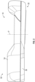
- the arm assembly 16 includes a contoured profile that contributes to a reduction in aerodynamic drag on the vehicle 10 during operation.
- the arm assembly 16 includes a carrier base 30 for attaching to the vehicle cab 12 and a pivoting portion 32 that pivots relative to the carrier base 30.
- the pivoting portion 32 supports at least one of the rearward facing camera 20 or a conventional mirror 21 adjacent a distal end of the arm assembly 16.
- the arm assembly 16 could be used with only the mirror 21 and not the camera 20.
- the pivoting portion 32 also includes an upper fairing 34 and a lower fairing 36 that enclose a support arm 38 ( Figures 3 and 5 ).
- the support arm 38 forms a pivotable connection with the carrier base 30 as will be described in greater detail below. Because the arm assembly 16 is manually pivoted between a retracted ( Figures 8A ) and an extended position ( Figures 7A ), it does not include a motor to pivot the pivoting portion 32 relative to the carrier base 30. Additionally, the arm assembly 16 in the vicinity of the connection between the pivoting portion 32 and the carrier base 30 (See Figures 2 and 3 ) includes a smaller vertical dimension and therefore includes a smaller leading edge area. This reduces drag on the arm assembly 16 and improves fuel efficiency of the vehicle 10. In the illustrated example, a vertical height of the arm assembly 16 in the vicinity of the pivot axis P is between 50 mm and 70 mm (1.97 inches and 2.76 inches).
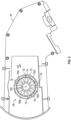
- a support detent ring 48 on the support arm 38 engages a carrier detent ring 46 on the carrier base 30 to allow the support arm 38 in the pivoting portion 32 to be selectively rotated relative to the carrier base 30 into one of a multiple predetermined positions.
- the carrier detent ring 46 and the support detent ring 48 are biased toward each other with a spring 52, such as a helical spring, to encourage the carrier detent ring 46 to move into an intermeshing position with the support detent ring 48.
- the spring 52 engages a retainer disk 45 fixed relative to the carrier base 30 on a first axial end and the support arm 38 on an opposite second axial end.
- the retainer disk 45 is secured relative to the carrier base 30 with a fastener 40 having a head engaging the carrier base 30 and a shaft extending through a passage on a central shaft 50.
- the central shaft 50 extends from the carrier base 30.
- a distal end of the fastener 40 is threaded and located outside of the passage on the central shaft 50.
- the retainer disk 45 includes a central opening for accepting the fastener 40 and a nut 42 engages the threaded distal end of the fastener 40 and the retainer disk 45 to secure the retainer disk 45 relative to the carrier base 30.
- the support arm 38 is allowed to selectively pivot or rotate relative to the carrier base 30 through the intermeshing of carrier detent ring 46 and the support detent ring 48.
- the force generated by the spring 52 provides a biasing force to move the carrier detent ring 46 into the intermeshing arrangement with the support detent ring 48.
- this force is overcome by pivoting the support arm 38 which compresses the spring 52.
- the carrier detent ring 46 includes a ring formed by a cylindrical wall that extends from a body portion of the carrier base 30.
- the carrier detent ring 46 can be integrally formed with the carrier base 30 or the carrier detent ring 46 can be removably attached to the carrier base 30.
- a distal end of the carrier detent ring 46 includes a plurality of projections 60 that are circumferentially spaced or offset from adj acent projections 60 by a corresponding one of a plurality of channels 62. Therefore, the projections 60 are located at a distal end of the cylindrical wall at a greater distance from the carrier base 30 than the channels 62.
- the projections 60 include a first set of projections 60A extending a first arcuate distance relative to a central longitudinal axis S of the central shaft 50 and a second single projection 60B that extends a second arcuate distance relative to the axis S. Also, each of the channels 62 separating the projections 60A extend for a common or singular arcuate distance relative to the axis S. Additionally, the second singular projection 60B extends for an arcuate distance of between 40 and 60 degrees around the carrier detent ring 46 relative to the axis S. Furthermore, the cylindrical wall including the projections 60 and the channels 62 are spaced from the central shaft 50 to accommodate the spring 52. In this disclosure, arcuate distances have a single or common radial distance relative to an axis unless stated otherwise.
- each of the five projections 60 include a projection surface defining an axially outer surface of the projection 60 and each of the five channels 62 include a channel surface defining an axially outer surface of the channel 62.
- the projection surfaces and the channel surfaces are planar. However, the projection surfaces and the channel surfaces could be curved with a varying distance from the body portion of the carrier base 30. The above arcuate distance for the single projection 60B in degrees are in relation to the axially outer surface of the single projection 60B.
- Adjacent projection surfaces of the projections 60 and channel surfaces of the channels 62 are connected by one of a plurality of transition surfaces 65.
- the transition surfaces 65 are transverse to both the projection surfaces and the channel surfaces not perpendicular to either one. This facilitates rotational movement of the carrier detent ring 46 with the support detent ring 48 when pivoting the support arm 38 relative to the carrier base 30 because the transition surfaces 65 operate as ramps.
- the support detent ring 48 extends from a bottom side of the support arm 38.
- the support detent ring 48 faces towards the carrier detent ring 46 when assembled.
- the support arm 38 includes a proximal end having a curvature to facilitate pivoting relative to the carrier base 30 and a distal end for securing a camera 20 or mirror 21.
- the support detent ring 48 is integrally formed with the support arm 38.
- the support detent ring 48 is removably attached to the support arm 38.
- the support detent ring 48 includes radially inner and outer cylindrical walls 74, 75 relative to an axis SR of a central opening in the support detent ring 48.
- the axis SR is colinear with the axis P and the axis S.
- the radially inner and outer walls 74, 75 at least partially surround a series of projections 76 and channels 78 located in a recessed area between the radially inner and outer walls 74, 75.
- One feature of the radially inner and outer walls 74, 75 is to improve alignment between the support detent ring 48 and the carrier detent ring 46.
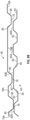
- Each of the four projections 76 include a projection surface defining an axially outer most surface of the projection 76 and each of the four channels 78 include an axially outer most surface of the channel 78. Adjacent axially outer most surfaces of the projections 76 and channels 78 are connected by a transition surface 80. The transition surfaces 80 are transverse to both the outer surfaces of the projections 76 and the channels 78 and the projections 76 and not perpendicular.
- a first set of channels 78A of the channels 78 extend for a common or singular first arcuate distance relative the axis SR of the support detent ring 48.
- a second channel 78B of the channels 78 extends for a second arcuate distance about the axis SR with the second arcuate distance extending between 60 and 120 degrees around the axis SR.
- the second arcuate distance extends between 75 and 105 degrees around the support detent ring 48.
- the above arcuate distances in degrees correspond to the axially outer most surface of the second channel 78B.
- the second singular projection 60B and one of the projections 60A are located in the second channel 78B as shown in Figure 6B .
- the projection 60B located in the channel 78B is immediately adjacent one of the projections 76.
- the projection 60B will engage the outer surface of at least one of the projections 76 on the carrier base 30. This prevents the carrier detent ring 46 from intermeshing with the support detent ring 48 because the projection 60B includes a larger circumferential distance than the channels 78A as shown in Figure 8B .
- a first stop 64 and a second stop 66 are located radially outward from the carrier detent ring 46 relative to axis S on the carrier base 30.
- a stop surface 64A, 66A on the first and second projections 64, 66, respectively, are located in a radially overlapping position relative to the axis SR.
- a stop projection 68 is located on the support arm 38 and positioned to contact the stop surfaces 64A when the support arm 38 is rotated as shown in Figure 8A and the stop surface 66B when the support arm 38 is rotated as shown in Figure 7A .
- the interaction between the first and second projections 64, 66 and the stop projection 68 prevents over rotation of the support arm 38 relative to the carrier base 30.
- the first and second stop projections 64, 66 and the stop projection 68 are also positioned to prevent intermeshing of the carrier detent ring 46 with the support detent ring 48.
Landscapes
- Engineering & Computer Science (AREA)
- Mechanical Engineering (AREA)
- Multimedia (AREA)
- Physics & Mathematics (AREA)
- General Physics & Mathematics (AREA)
- Accessories Of Cameras (AREA)
- Pivots And Pivotal Connections (AREA)
Claims (11)
- Fahrzeugarmanordnung (16) die Folgendes umfasst:eine Trägerbasis (30) zum Anbringen an einem Fahrzeug (10);einen Tragarm (36), der relativ zur Trägerbasis (30) drehbar montiert ist;einen ersten Rastring (46) einschließlich einer Vielzahl von ersten Rastvorsprüngen (60), die in Umfangsrichtung durch eine Vielzahl von ersten Rastkanälen (62) versetzt sind; undeinen zweiten Rastring (48) einschließlich einer Vielzahl von zweiten Rastvorsprüngen (76), die in Umfangsrichtung durch eine Vielzahl von zweiten Rastkanälen (78) versetzt sind;wobei der erste Rastring (46) relativ zu einem von der Trägerbasis (30) oder dem Tragarm (36) fest ist und der zweite Rastring (48) relativ zu dem anderen von der Trägerbasis (30) und dem Tragarm (36) fest ist;wobei der erste Rastring (46) in einer ineinandergreifenden Anordnung ist, wenn der zweite Rastring (48) in einer ersten Drehposition ist, und in einer nicht ineinandergreifenden Anordnung, wenn er in einer zweiten Drehposition ist;wobei in der zweiten Drehposition eine relativ zur Trägerbasis (30) feste erste Anschlagfläche (64) in Eingriff mit einem relativ zum Tragarm (36) festen Anschlag (66) steht;wobei die Vielzahl von ersten Rastvorsprüngen (60) Folgendes einschließen:mindestens zwei erste Vorsprünge (60A), die sich jeweils in einem ersten bogenförmigen Abstand um den ersten Rastring (46) erstrecken; undeinen einzelnen ersten Vorsprung (60B), der sich in einem zweiten bogenförmigen Abstand um den ersten Rastring (46) erstreckt, wobei der zweite bogenförmige Abstand größer als der erste bogenförmige Abstand ist; undwobei sich der einzelne aus der Vielzahl von ersten Rastvorsprüngen (60B) und einer der mindestens zwei ersten Vorsprünge (60A) zusammen in einem bogenförmigen Abstand von mindestens 60 Grad und weniger als 120 Grad um den ersten Rastring (46) erstrecken.
- Anordnung (16) nach Anspruch 1, wobei die Vielzahl von zweiten Rastkanälen (78) einen ersten Satz von sich über eine erste bogenförmige Länge erstreckenden zweiten Kanälen (78A) und einen sich über einen dritten bogenförmigen Abstand erstreckenden einzelnen zweiten Kanal (78B) einschließen und der dritte bogenförmige Abstand größer ist als der erste bogenförmige Abstand.
- Anordnung (16) nach Anspruch 2, wobei der dritte bogenförmige Abstand größer ist als der zweite bogenförmige Abstand.
- Anordnung (16) nach einem vorhergehenden Anspruch, wobei der eine der mindestens zwei ersten Vorsprünge (60A) und der einzelne erste Vorsprung (60B) zum Ineinandergreifen mit dem einzelnen zweiten Kanal (62B) konfiguriert sind.
- Anordnung (16) nach einem der Ansprüche 2 bis 4, wobei sich der einzelne zweite Kanal (78B) in einem bogenförmigen Abstand von mindestens 60 Grad und weniger als 120 Grad um den zweiten Rastring (48) erstreckt.
- Anordnung (16) nach einem der Ansprüche 2 bis 5, wobei sich der einzelne zweite Kanal (78B) in einem bogenförmigen Abstand von mindestens 75 Grad und weniger als 105 Grad um den zweiten Rastring (48) erstreckt.
- Anordnung (16) nach einem vorhergehenden Anspruch, wobei der zweite Rastring (48) eine radial innere Wand (74) und eine radial äußere Wand (75) einschließt, die einen ausgesparten Bereich für die Vielzahl von zweiten Vorsprüngen (76) und die Vielzahl von zweiten Kanälen (78) bildet.
- Anordnung (16) nach einem vorhergehenden Anspruch, wobei jeder der Vielzahl von ersten Rastkanälen (62) eine axial äußere Fläche einschließt, die eben ist, jeder der Vielzahl von ersten Rastvorsprüngen (60) eine axial äußere Fläche einschließt, die eben ist, und jeder der Vielzahl von ersten Rastkanälen (62) mit einem benachbarten der Vielzahl von ersten Rastvorsprüngen (60) durch eine ebene Verbindungsfläche (65) verbunden ist, die quer zu seiner ebenen äußeren Fläche der ersten Rastkanäle und seiner ebenen äußeren Fläche der ersten Rastvorsprünge verläuft.
- Anordnung (16) nach einem vorhergehenden Anspruch, wobei der erste Rastring (46) einstückig mit dem einen von der Trägerbasis (30) oder dem Tragarm (36) ausgebildet ist und der zweite Rastring (48) einstückig mit dem anderen von der Trägerbasis (30) oder dem Tragarm (36) ausgebildet ist.
- Anordnung (16) nach einem vorhergehenden Anspruch, wobei der erste Rastring (46) abnehmbar an einem von der Trägerbasis (30) oder dem Tragarm (36) angebracht ist und der zweite Rastring (48) abnehmbar an dem anderen von der Trägerbasis (30) oder dem Tragarm (36) angebracht ist.
- Anordnung (16) nach einem vorhergehenden Anspruch, die ferner mindestens eine relativ zum Tragarm (36) feste Kamera (20) umfasst.
Applications Claiming Priority (1)
| Application Number | Priority Date | Filing Date | Title |
|---|---|---|---|
| US17/679,868 US11958419B2 (en) | 2022-02-24 | 2022-02-24 | Collapsible vehicle camera arm assembly |
Publications (2)
| Publication Number | Publication Date |
|---|---|
| EP4234332A1 EP4234332A1 (de) | 2023-08-30 |
| EP4234332B1 true EP4234332B1 (de) | 2024-09-18 |
Family
ID=85283620
Family Applications (1)
| Application Number | Title | Priority Date | Filing Date |
|---|---|---|---|
| EP23157350.2A Active EP4234332B1 (de) | 2022-02-24 | 2023-02-17 | Zusammenklappbare fahrzeugkameraarmanordnung |
Country Status (3)
| Country | Link |
|---|---|
| US (1) | US11958419B2 (de) |
| EP (1) | EP4234332B1 (de) |
| CN (1) | CN116639054A (de) |
Citations (7)
| Publication number | Priority date | Publication date | Assignee | Title |
|---|---|---|---|---|
| US20130015314A1 (en) | 2011-07-13 | 2013-01-17 | Lang-Mekra North America, Llc | Pivoting detent joint for a vehicle mirror assembly |
| US20130125344A1 (en) | 2011-11-22 | 2013-05-23 | Lang-Mekra North America, Llc | Engaging Surfaces Arrangement For A Pivoting Detent Joint |
| EP3339667A1 (de) | 2016-12-21 | 2018-06-27 | MEKRA LANG GmbH & Co. KG | Lageranordnung, befestigungsvorrichtung hiermit, sowie anbauteil für fahrzeuge mit dieser befestigungsvorrichtung |
| US20190085889A1 (en) | 2017-09-19 | 2019-03-21 | SMR Patents S.à.r.l. | Locking ring, rear view device and vehicle |
| EP3476654A1 (de) | 2017-10-26 | 2019-05-01 | MEKRA Lang GmbH & Co. KG | Haltevorrichtung für ein kraftfahrzeug |
| US20200088232A1 (en) | 2017-09-19 | 2020-03-19 | SMR Patents S.à.r.l. | Locking ring, rear view device and vehicle |
| DE102019219148A1 (de) | 2018-12-18 | 2020-06-18 | Magna Mirrors Holding Gmbh | Fahrzeugaußenspiegel mit Abklappfunktion |
Family Cites Families (55)
| Publication number | Priority date | Publication date | Assignee | Title |
|---|---|---|---|---|
| GB1243179A (en) | 1967-10-03 | 1971-08-18 | Unimec Designs Ltd | Improvements relating to mirror devices for motor vehicles |
| CA861762A (en) | 1969-01-10 | 1971-01-26 | Dominion Auto Accessories Limited | Hinge joint assemblies |
| US4186905A (en) | 1975-06-09 | 1980-02-05 | Dominion Auto Accessories Limited | Retractable truck mirror |
| JPH06953U (ja) | 1992-06-09 | 1994-01-11 | 市光工業株式会社 | 自動車用後方視認装置 |
| JPH09175272A (ja) | 1995-12-28 | 1997-07-08 | Ichikoh Ind Ltd | 車両用監視カメラ |
| DE19906150A1 (de) | 1999-02-10 | 2000-09-07 | Magna Reflex Holding Gmbh | Fahrzeugaußenspiegel und Verfahren zu dessen Steuerung |
| US6286968B1 (en) | 1999-09-07 | 2001-09-11 | Lang-Mekra North America, Llc | Mirror mounting assembly with stop feature |
| DE19961313B4 (de) | 1999-12-18 | 2005-06-02 | Bayerische Motoren Werke Ag | Kameraeinrichtung für ein Fahrzeug |
| CA2444672A1 (en) | 2001-04-20 | 2002-10-31 | Sachtler Corporation Of America | Heavy-duty stabilized camera head with camera position sensing |
| KR100858406B1 (ko) | 2001-10-30 | 2008-09-11 | 쉐프네커 비젼 시스템즈 오스트레일리아 프로프라이어터리 리미티드 | 파워 텔레스코핑 차량 미러 조립체 |
| DE10218228A1 (de) | 2002-04-24 | 2003-11-06 | Volkswagen Ag | Verfahren und Einrichtung zur Funktionskontrolle einer Videokamera in einem Fahrzeug |
| JP2003320898A (ja) | 2002-04-26 | 2003-11-11 | Sony Corp | 車両用サイドミラー装置 |
| US7965336B2 (en) | 2002-11-14 | 2011-06-21 | Donnelly Corporation | Imaging system for vehicle |
| DE102004039450A1 (de) | 2004-08-13 | 2006-03-09 | 2W Technische Informations Gmbh | Einparkhilfe für Fahrzeuge |
| EP1647867A1 (de) | 2004-10-11 | 2006-04-19 | The Swatch Group Management Services AG | Vergrösserungsvorrichtung für Uhren |
| EP1736360A1 (de) | 2005-06-23 | 2006-12-27 | Mazda Motor Corporation | Toter Winkelerfassungs-System für Kraftfahrzeug |
| DE102008046980B3 (de) | 2008-09-11 | 2010-06-02 | Mekra Lang Gmbh & Co. Kg | Spiegelhalterung zum Befestigen eines Spiegels an einem Fahrzeug und Spiegel mit einer solchen Spiegelhalterung |
| JP2011003117A (ja) | 2009-06-22 | 2011-01-06 | Central Motor Co Ltd | 後方視認支援システム |
| KR101199070B1 (ko) | 2009-12-03 | 2012-11-07 | 현대자동차주식회사 | 변속레인지 검출장치 |
| DE102010005638A1 (de) | 2010-01-25 | 2011-07-28 | Valeo Schalter und Sensoren GmbH, 74321 | Verfahren zum Anzeigen zumindest eines Bildes einer Fahrzeugumgebung auf einer Anzeigeeinrichtung in einem Fahrzeug. Fahrerassistenzeinrichtung für ein Fahrzeugund Fahrzeug mit einer Fahrerassistenzeinrichtung |
| US9827913B2 (en) | 2010-02-10 | 2017-11-28 | Magna Mirrors Of America, Inc. | Exterior rearview mirror assembly |
| CN202088981U (zh) | 2011-05-31 | 2011-12-28 | 伟速达(中国)汽车安全系统有限公司 | 汽车后视摄像头装置控制器 |
| US8830317B2 (en) | 2011-11-23 | 2014-09-09 | Robert Bosch Gmbh | Position dependent rear facing camera for pickup truck lift gates |
| US10231787B2 (en) | 2012-01-12 | 2019-03-19 | Brainlab Ag | Method and system for medical tracking using a plurality of camera positions |
| DE102012003561A1 (de) | 2012-02-23 | 2013-08-29 | Daimler Ag | Kameraanordnung für einen Kraftwagen und Verfahren zum Betreiben einer Kameraanordnung |
| JP5918022B2 (ja) | 2012-05-21 | 2016-05-18 | 株式会社東海理化電機製作所 | 車両用ミラー装置 |
| DE102012015395B3 (de) | 2012-08-03 | 2013-11-28 | Mekra Lang Gmbh & Co. Kg | Kameraarm für eine Spiegelersatzsystem-Kamera eines Kraftfahrzeugs |
| JP6099333B2 (ja) | 2012-08-30 | 2017-03-22 | 富士通テン株式会社 | 画像生成装置、画像表示システム、パラメータ取得装置、画像生成方法及びパラメータ取得方法 |
| DE102013002111B4 (de) | 2013-02-08 | 2021-11-18 | Mekra Lang Gmbh & Co. Kg | Sichtsystem für Fahrzeuge, insbesondere Nutzfahrzeuge |
| WO2015017572A1 (en) | 2013-08-01 | 2015-02-05 | Contour, Llc | Orientation control of an image sensor of a portable digital video camera |
| DE102013217081B4 (de) | 2013-08-27 | 2019-11-21 | Volkswagen Aktiengesellschaft | Vorrichtung und Verfahren zur Positionserkennung |
| DE102013221879A1 (de) | 2013-10-28 | 2015-05-21 | Continental Teves Ag & Co. Ohg | Fahrerassistenzsystem mit einer Kamera mit Verstellmechanismus |
| DE102014101685A1 (de) | 2014-02-11 | 2015-08-13 | Huf Hülsbeck & Fürst Gmbh & Co. Kg | Kameravorrichtung |
| DE102014006961A1 (de) | 2014-05-13 | 2015-11-19 | Man Truck & Bus Ag | Fahrzeug, insbesondere Nutzfahrzeug, mit einem Kamera-Monitor-System als Spiegelersatzsystem sowie Verfahren zur Betätigung eines derartigen Kamera-Monitor-Systems |
| DE102014214128B4 (de) | 2014-07-21 | 2016-02-04 | Mekra Lang Gmbh & Co. Kg | Trägervorrichtung für die Befestigung einer bildgebenden Einrichtung eines indirekten Sichtsystems an einem Fahrzeug sowie indirektes Sichtsystem hiermit |
| DE102014111068B4 (de) | 2014-08-04 | 2023-11-23 | Dr. Ing. H.C. F. Porsche Aktiengesellschaft | Kraftfahrzeug |
| JP6383654B2 (ja) | 2014-12-16 | 2018-08-29 | 祥忠 川越 | サイドリアビュー確認装置 |
| US9744907B2 (en) | 2014-12-29 | 2017-08-29 | Gentex Corporation | Vehicle vision system having adjustable displayed field of view |
| DE102015117777A1 (de) | 2015-04-30 | 2016-11-03 | Huf Hülsbeck & Fürst Gmbh & Co. Kg | Rückfahrkameraeinrichtung für ein Kraftfahrzeug |
| US9449390B1 (en) | 2015-05-19 | 2016-09-20 | Ford Global Technologies, Llc | Detecting an extended side view mirror |
| US9800778B2 (en) | 2015-07-21 | 2017-10-24 | Qualcomm Incorporated | Camera orientation notification system |
| NL2015468B1 (nl) | 2015-09-18 | 2017-04-19 | MCI (Mirror Controls International) Netherlands B V | Beweegbare beeldopname inrichting en voertuig voorzien van een dergelijke inrichting. |
| KR101702888B1 (ko) | 2015-10-12 | 2017-02-06 | 현대자동차주식회사 | 차량용 시야 각도 조절장치, 이를 포함하는 차량 및 차량용 시야 각도 조절방법 |
| US10166925B2 (en) | 2015-11-12 | 2019-01-01 | SMR Patents S.à.r.l. | Rear view element folding device |
| DE202015106118U1 (de) | 2015-11-12 | 2015-11-30 | SMR Patents S.à.r.l. | Rückblickelement-Klappvorrichtung |
| DE102015122984A1 (de) | 2015-11-17 | 2017-05-18 | Huf Hülsbeck & Fürst Gmbh & Co. Kg | Rückfahrkameraeinrichtung für Kraftfahrzeuge |
| NL2015897B1 (nl) | 2015-12-02 | 2017-06-28 | MCI (Mirror Controls International) Netherlands B V | Bevestigingsconstructie, in het bijzonder voor een buitenzichteenheid van een motorvoertuig. |
| DE102015121405A1 (de) | 2015-12-09 | 2017-06-14 | Huf Hülsbeck & Fürst GmbH & Co KG | Vorrichtung zur Positionsbestimmung |
| DE102015122997A1 (de) | 2015-12-30 | 2017-07-06 | Huf Hülsbeck & Fürst Gmbh & Co. Kg | Verfahren zur Darstellung eines rückwärtigen Außenbereiches eines Fahrzeuges |
| DE102016102508B4 (de) | 2016-02-12 | 2020-03-19 | Ficosa International Gmbh | Schwenkeinrichtung |
| WO2017178859A1 (en) | 2016-04-15 | 2017-10-19 | Volvo Truck Corporation | Camera used as a vehicle size reference and vehicle equipped with the same |
| DE102017112062A1 (de) | 2017-06-01 | 2018-12-06 | Man Truck & Bus Ag | Spiegelersatz- oder Spiegelergänzungskonstruktion mit Positionierungserkennung |
| EP3437930B1 (de) | 2017-08-01 | 2021-07-28 | SMR Patents S.à.r.l. | Kameravorrichtung und kraftfahrzeug mit derartiger vorrichtung |
| JP6939368B2 (ja) | 2017-10-04 | 2021-09-22 | トヨタ自動車株式会社 | 画像表示装置 |
| DE102018215995A1 (de) | 2018-09-20 | 2020-03-26 | Bayerische Motoren Werke Aktiengesellschaft | Sensorhalter für ein Fahrzeug |
-
2022
- 2022-02-24 US US17/679,868 patent/US11958419B2/en active Active
-
2023
- 2023-02-17 EP EP23157350.2A patent/EP4234332B1/de active Active
- 2023-02-24 CN CN202310191985.XA patent/CN116639054A/zh active Pending
Patent Citations (7)
| Publication number | Priority date | Publication date | Assignee | Title |
|---|---|---|---|---|
| US20130015314A1 (en) | 2011-07-13 | 2013-01-17 | Lang-Mekra North America, Llc | Pivoting detent joint for a vehicle mirror assembly |
| US20130125344A1 (en) | 2011-11-22 | 2013-05-23 | Lang-Mekra North America, Llc | Engaging Surfaces Arrangement For A Pivoting Detent Joint |
| EP3339667A1 (de) | 2016-12-21 | 2018-06-27 | MEKRA LANG GmbH & Co. KG | Lageranordnung, befestigungsvorrichtung hiermit, sowie anbauteil für fahrzeuge mit dieser befestigungsvorrichtung |
| US20190085889A1 (en) | 2017-09-19 | 2019-03-21 | SMR Patents S.à.r.l. | Locking ring, rear view device and vehicle |
| US20200088232A1 (en) | 2017-09-19 | 2020-03-19 | SMR Patents S.à.r.l. | Locking ring, rear view device and vehicle |
| EP3476654A1 (de) | 2017-10-26 | 2019-05-01 | MEKRA Lang GmbH & Co. KG | Haltevorrichtung für ein kraftfahrzeug |
| DE102019219148A1 (de) | 2018-12-18 | 2020-06-18 | Magna Mirrors Holding Gmbh | Fahrzeugaußenspiegel mit Abklappfunktion |
Also Published As
| Publication number | Publication date |
|---|---|
| US11958419B2 (en) | 2024-04-16 |
| US20230264636A1 (en) | 2023-08-24 |
| CN116639054A (zh) | 2023-08-25 |
| EP4234332A1 (de) | 2023-08-30 |
Similar Documents
| Publication | Publication Date | Title |
|---|---|---|
| US7762737B2 (en) | System and method for stowage compartment pivot assembly | |
| EP2594454B1 (de) | Lenkvorrichtung | |
| US7490945B2 (en) | Wear-proof détente for folding mirrors | |
| US20060237987A1 (en) | Power seat slide device for vehicle | |
| US20130109526A1 (en) | Geared motor | |
| US6234040B1 (en) | Rotating, traveling energy absorber for steering column | |
| EP2055612A2 (de) | Lenksäulenanordnung | |
| CN107264408B (zh) | 视觉辨认装置的视觉辨认角度调整机构 | |
| US20100119325A1 (en) | Stud retaining fastener assembly | |
| US20240300566A1 (en) | Retractable steering wheel arrangement with non-planar steering wheel rim | |
| US11345390B2 (en) | Steering device | |
| EP4234332A1 (de) | Zusammenklappbare fahrzeugkameraarmanordnung | |
| US6748774B2 (en) | Forward firing shaft lock mechanism | |
| JP5983070B2 (ja) | ステアリングロック装置 | |
| US8157395B2 (en) | Folding outer mirror | |
| US6390556B1 (en) | Vehicle seat fitted with a pivot mechanism | |
| CN107264409B (zh) | 视觉辨认装置的视觉辨认角度调整机构 | |
| CN107264411B (zh) | 视觉辨认装置的视觉辨认角度调整机构 | |
| US20240336295A1 (en) | Adjustment device for steering columns of vehicles | |
| US7516682B2 (en) | Clamp for friction lock mechanism on steering column | |
| EP4313728B1 (de) | Einziehbare lenkradanordnung für ein steer-by-wire-lenksystem | |
| US11912333B2 (en) | Steering device | |
| US20260015031A1 (en) | Steering device | |
| US7874687B1 (en) | Multi-function side detent for vehicular mirror | |
| US20250162483A1 (en) | Bushing for oscillating free pivot |
Legal Events
| Date | Code | Title | Description |
|---|---|---|---|
| PUAI | Public reference made under article 153(3) epc to a published international application that has entered the european phase |
Free format text: ORIGINAL CODE: 0009012 |
|
| STAA | Information on the status of an ep patent application or granted ep patent |
Free format text: STATUS: THE APPLICATION HAS BEEN PUBLISHED |
|
| AK | Designated contracting states |
Kind code of ref document: A1 Designated state(s): AL AT BE BG CH CY CZ DE DK EE ES FI FR GB GR HR HU IE IS IT LI LT LU LV MC ME MK MT NL NO PL PT RO RS SE SI SK SM TR |
|
| STAA | Information on the status of an ep patent application or granted ep patent |
Free format text: STATUS: REQUEST FOR EXAMINATION WAS MADE |
|
| 17P | Request for examination filed |
Effective date: 20240228 |
|
| RBV | Designated contracting states (corrected) |
Designated state(s): AL AT BE BG CH CY CZ DE DK EE ES FI FR GB GR HR HU IE IS IT LI LT LU LV MC ME MK MT NL NO PL PT RO RS SE SI SK SM TR |
|
| GRAP | Despatch of communication of intention to grant a patent |
Free format text: ORIGINAL CODE: EPIDOSNIGR1 |
|
| STAA | Information on the status of an ep patent application or granted ep patent |
Free format text: STATUS: GRANT OF PATENT IS INTENDED |
|
| RIC1 | Information provided on ipc code assigned before grant |
Ipc: B60R 1/25 20220101ALI20240318BHEP Ipc: B60R 1/06 20060101AFI20240318BHEP |
|
| INTG | Intention to grant announced |
Effective date: 20240408 |
|
| GRAS | Grant fee paid |
Free format text: ORIGINAL CODE: EPIDOSNIGR3 |
|
| GRAA | (expected) grant |
Free format text: ORIGINAL CODE: 0009210 |
|
| STAA | Information on the status of an ep patent application or granted ep patent |
Free format text: STATUS: THE PATENT HAS BEEN GRANTED |
|
| AK | Designated contracting states |
Kind code of ref document: B1 Designated state(s): AL AT BE BG CH CY CZ DE DK EE ES FI FR GB GR HR HU IE IS IT LI LT LU LV MC ME MK MT NL NO PL PT RO RS SE SI SK SM TR |
|
| REG | Reference to a national code |
Ref country code: GB Ref legal event code: FG4D |
|
| REG | Reference to a national code |
Ref country code: CH Ref legal event code: EP |
|
| REG | Reference to a national code |
Ref country code: DE Ref legal event code: R096 Ref document number: 602023000559 Country of ref document: DE |
|
| REG | Reference to a national code |
Ref country code: IE Ref legal event code: FG4D |
|
| REG | Reference to a national code |
Ref country code: SE Ref legal event code: TRGR |
|
| REG | Reference to a national code |
Ref country code: LT Ref legal event code: MG9D |
|
| PG25 | Lapsed in a contracting state [announced via postgrant information from national office to epo] |
Ref country code: NO Free format text: LAPSE BECAUSE OF FAILURE TO SUBMIT A TRANSLATION OF THE DESCRIPTION OR TO PAY THE FEE WITHIN THE PRESCRIBED TIME-LIMIT Effective date: 20241218 |
|
| PG25 | Lapsed in a contracting state [announced via postgrant information from national office to epo] |
Ref country code: GR Free format text: LAPSE BECAUSE OF FAILURE TO SUBMIT A TRANSLATION OF THE DESCRIPTION OR TO PAY THE FEE WITHIN THE PRESCRIBED TIME-LIMIT Effective date: 20241219 Ref country code: FI Free format text: LAPSE BECAUSE OF FAILURE TO SUBMIT A TRANSLATION OF THE DESCRIPTION OR TO PAY THE FEE WITHIN THE PRESCRIBED TIME-LIMIT Effective date: 20240918 |
|
| PG25 | Lapsed in a contracting state [announced via postgrant information from national office to epo] |
Ref country code: BG Free format text: LAPSE BECAUSE OF FAILURE TO SUBMIT A TRANSLATION OF THE DESCRIPTION OR TO PAY THE FEE WITHIN THE PRESCRIBED TIME-LIMIT Effective date: 20240918 |
|
| PG25 | Lapsed in a contracting state [announced via postgrant information from national office to epo] |
Ref country code: LV Free format text: LAPSE BECAUSE OF FAILURE TO SUBMIT A TRANSLATION OF THE DESCRIPTION OR TO PAY THE FEE WITHIN THE PRESCRIBED TIME-LIMIT Effective date: 20240918 |
|
| PG25 | Lapsed in a contracting state [announced via postgrant information from national office to epo] |
Ref country code: HR Free format text: LAPSE BECAUSE OF FAILURE TO SUBMIT A TRANSLATION OF THE DESCRIPTION OR TO PAY THE FEE WITHIN THE PRESCRIBED TIME-LIMIT Effective date: 20240918 |
|
| REG | Reference to a national code |
Ref country code: NL Ref legal event code: MP Effective date: 20240918 |
|
| PG25 | Lapsed in a contracting state [announced via postgrant information from national office to epo] |
Ref country code: RS Free format text: LAPSE BECAUSE OF FAILURE TO SUBMIT A TRANSLATION OF THE DESCRIPTION OR TO PAY THE FEE WITHIN THE PRESCRIBED TIME-LIMIT Effective date: 20241218 |
|
| PG25 | Lapsed in a contracting state [announced via postgrant information from national office to epo] |
Ref country code: RS Free format text: LAPSE BECAUSE OF FAILURE TO SUBMIT A TRANSLATION OF THE DESCRIPTION OR TO PAY THE FEE WITHIN THE PRESCRIBED TIME-LIMIT Effective date: 20241218 Ref country code: NO Free format text: LAPSE BECAUSE OF FAILURE TO SUBMIT A TRANSLATION OF THE DESCRIPTION OR TO PAY THE FEE WITHIN THE PRESCRIBED TIME-LIMIT Effective date: 20241218 Ref country code: LV Free format text: LAPSE BECAUSE OF FAILURE TO SUBMIT A TRANSLATION OF THE DESCRIPTION OR TO PAY THE FEE WITHIN THE PRESCRIBED TIME-LIMIT Effective date: 20240918 Ref country code: HR Free format text: LAPSE BECAUSE OF FAILURE TO SUBMIT A TRANSLATION OF THE DESCRIPTION OR TO PAY THE FEE WITHIN THE PRESCRIBED TIME-LIMIT Effective date: 20240918 Ref country code: GR Free format text: LAPSE BECAUSE OF FAILURE TO SUBMIT A TRANSLATION OF THE DESCRIPTION OR TO PAY THE FEE WITHIN THE PRESCRIBED TIME-LIMIT Effective date: 20241219 Ref country code: FI Free format text: LAPSE BECAUSE OF FAILURE TO SUBMIT A TRANSLATION OF THE DESCRIPTION OR TO PAY THE FEE WITHIN THE PRESCRIBED TIME-LIMIT Effective date: 20240918 Ref country code: BG Free format text: LAPSE BECAUSE OF FAILURE TO SUBMIT A TRANSLATION OF THE DESCRIPTION OR TO PAY THE FEE WITHIN THE PRESCRIBED TIME-LIMIT Effective date: 20240918 |
|
| REG | Reference to a national code |
Ref country code: AT Ref legal event code: MK05 Ref document number: 1724436 Country of ref document: AT Kind code of ref document: T Effective date: 20240918 |
|
| PG25 | Lapsed in a contracting state [announced via postgrant information from national office to epo] |
Ref country code: NL Free format text: LAPSE BECAUSE OF FAILURE TO SUBMIT A TRANSLATION OF THE DESCRIPTION OR TO PAY THE FEE WITHIN THE PRESCRIBED TIME-LIMIT Effective date: 20240918 |
|
| PG25 | Lapsed in a contracting state [announced via postgrant information from national office to epo] |
Ref country code: IS Free format text: LAPSE BECAUSE OF FAILURE TO SUBMIT A TRANSLATION OF THE DESCRIPTION OR TO PAY THE FEE WITHIN THE PRESCRIBED TIME-LIMIT Effective date: 20250118 Ref country code: PT Free format text: LAPSE BECAUSE OF FAILURE TO SUBMIT A TRANSLATION OF THE DESCRIPTION OR TO PAY THE FEE WITHIN THE PRESCRIBED TIME-LIMIT Effective date: 20250120 |
|
| PG25 | Lapsed in a contracting state [announced via postgrant information from national office to epo] |
Ref country code: RO Free format text: LAPSE BECAUSE OF FAILURE TO SUBMIT A TRANSLATION OF THE DESCRIPTION OR TO PAY THE FEE WITHIN THE PRESCRIBED TIME-LIMIT Effective date: 20240918 Ref country code: SM Free format text: LAPSE BECAUSE OF FAILURE TO SUBMIT A TRANSLATION OF THE DESCRIPTION OR TO PAY THE FEE WITHIN THE PRESCRIBED TIME-LIMIT Effective date: 20240918 |
|
| PG25 | Lapsed in a contracting state [announced via postgrant information from national office to epo] |
Ref country code: ES Free format text: LAPSE BECAUSE OF FAILURE TO SUBMIT A TRANSLATION OF THE DESCRIPTION OR TO PAY THE FEE WITHIN THE PRESCRIBED TIME-LIMIT Effective date: 20240918 |
|
| PG25 | Lapsed in a contracting state [announced via postgrant information from national office to epo] |
Ref country code: EE Free format text: LAPSE BECAUSE OF FAILURE TO SUBMIT A TRANSLATION OF THE DESCRIPTION OR TO PAY THE FEE WITHIN THE PRESCRIBED TIME-LIMIT Effective date: 20240918 Ref country code: AT Free format text: LAPSE BECAUSE OF FAILURE TO SUBMIT A TRANSLATION OF THE DESCRIPTION OR TO PAY THE FEE WITHIN THE PRESCRIBED TIME-LIMIT Effective date: 20240918 |
|
| PG25 | Lapsed in a contracting state [announced via postgrant information from national office to epo] |
Ref country code: PL Free format text: LAPSE BECAUSE OF FAILURE TO SUBMIT A TRANSLATION OF THE DESCRIPTION OR TO PAY THE FEE WITHIN THE PRESCRIBED TIME-LIMIT Effective date: 20240918 Ref country code: CZ Free format text: LAPSE BECAUSE OF FAILURE TO SUBMIT A TRANSLATION OF THE DESCRIPTION OR TO PAY THE FEE WITHIN THE PRESCRIBED TIME-LIMIT Effective date: 20240918 |
|
| PG25 | Lapsed in a contracting state [announced via postgrant information from national office to epo] |
Ref country code: IT Free format text: LAPSE BECAUSE OF FAILURE TO SUBMIT A TRANSLATION OF THE DESCRIPTION OR TO PAY THE FEE WITHIN THE PRESCRIBED TIME-LIMIT Effective date: 20240918 Ref country code: SK Free format text: LAPSE BECAUSE OF FAILURE TO SUBMIT A TRANSLATION OF THE DESCRIPTION OR TO PAY THE FEE WITHIN THE PRESCRIBED TIME-LIMIT Effective date: 20240918 |
|
| REG | Reference to a national code |
Ref country code: DE Ref legal event code: R026 Ref document number: 602023000559 Country of ref document: DE |
|
| PLBI | Opposition filed |
Free format text: ORIGINAL CODE: 0009260 |
|
| PLAX | Notice of opposition and request to file observation + time limit sent |
Free format text: ORIGINAL CODE: EPIDOSNOBS2 |
|
| PG25 | Lapsed in a contracting state [announced via postgrant information from national office to epo] |
Ref country code: DK Free format text: LAPSE BECAUSE OF FAILURE TO SUBMIT A TRANSLATION OF THE DESCRIPTION OR TO PAY THE FEE WITHIN THE PRESCRIBED TIME-LIMIT Effective date: 20240918 |
|
| 26 | Opposition filed |
Opponent name: QIP PATENT & RECHTDR. KUEHN & PARTNER MBB Effective date: 20250617 |
|
| PG25 | Lapsed in a contracting state [announced via postgrant information from national office to epo] |
Ref country code: MC Free format text: LAPSE BECAUSE OF FAILURE TO SUBMIT A TRANSLATION OF THE DESCRIPTION OR TO PAY THE FEE WITHIN THE PRESCRIBED TIME-LIMIT Effective date: 20240918 |
|
| PG25 | Lapsed in a contracting state [announced via postgrant information from national office to epo] |
Ref country code: LU Free format text: LAPSE BECAUSE OF NON-PAYMENT OF DUE FEES Effective date: 20250217 |
|
| PLBB | Reply of patent proprietor to notice(s) of opposition received |
Free format text: ORIGINAL CODE: EPIDOSNOBS3 |
|
| REG | Reference to a national code |
Ref country code: BE Ref legal event code: MM Effective date: 20250228 |
|
| PG25 | Lapsed in a contracting state [announced via postgrant information from national office to epo] |
Ref country code: FR Free format text: LAPSE BECAUSE OF NON-PAYMENT OF DUE FEES Effective date: 20250228 |
|
| PG25 | Lapsed in a contracting state [announced via postgrant information from national office to epo] |
Ref country code: BE Free format text: LAPSE BECAUSE OF NON-PAYMENT OF DUE FEES Effective date: 20250228 |
|
| PG25 | Lapsed in a contracting state [announced via postgrant information from national office to epo] |
Ref country code: IE Free format text: LAPSE BECAUSE OF NON-PAYMENT OF DUE FEES Effective date: 20250217 |
|
| PGFP | Annual fee paid to national office [announced via postgrant information from national office to epo] |
Ref country code: SE Payment date: 20260218 Year of fee payment: 4 |
|
| PGFP | Annual fee paid to national office [announced via postgrant information from national office to epo] |
Ref country code: DE Payment date: 20260217 Year of fee payment: 4 |