EP4233770A2 - Rollenmodul für medizinischen roboter, antriebsvorrichtung für medizinischen roboter und medizinischer roboter - Google Patents
Rollenmodul für medizinischen roboter, antriebsvorrichtung für medizinischen roboter und medizinischer roboter Download PDFInfo
- Publication number
- EP4233770A2 EP4233770A2 EP23179538.6A EP23179538A EP4233770A2 EP 4233770 A2 EP4233770 A2 EP 4233770A2 EP 23179538 A EP23179538 A EP 23179538A EP 4233770 A2 EP4233770 A2 EP 4233770A2
- Authority
- EP
- European Patent Office
- Prior art keywords
- roller
- module
- unit
- driving
- roller unit
- Prior art date
- Legal status (The legal status is an assumption and is not a legal conclusion. Google has not performed a legal analysis and makes no representation as to the accuracy of the status listed.)
- Granted
Links
Images


Classifications
-
- A—HUMAN NECESSITIES
- A61—MEDICAL OR VETERINARY SCIENCE; HYGIENE
- A61B—DIAGNOSIS; SURGERY; IDENTIFICATION
- A61B34/00—Computer-aided surgery; Manipulators or robots specially adapted for use in surgery
- A61B34/30—Surgical robots
-
- A—HUMAN NECESSITIES
- A61—MEDICAL OR VETERINARY SCIENCE; HYGIENE
- A61B—DIAGNOSIS; SURGERY; IDENTIFICATION
- A61B34/00—Computer-aided surgery; Manipulators or robots specially adapted for use in surgery
- A61B34/30—Surgical robots
- A61B34/35—Surgical robots for telesurgery
-
- A—HUMAN NECESSITIES
- A61—MEDICAL OR VETERINARY SCIENCE; HYGIENE
- A61B—DIAGNOSIS; SURGERY; IDENTIFICATION
- A61B34/00—Computer-aided surgery; Manipulators or robots specially adapted for use in surgery
- A61B34/20—Surgical navigation systems; Devices for tracking or guiding surgical instruments, e.g. for frameless stereotaxis
-
- A—HUMAN NECESSITIES
- A61—MEDICAL OR VETERINARY SCIENCE; HYGIENE
- A61M—DEVICES FOR INTRODUCING MEDIA INTO, OR ONTO, THE BODY; DEVICES FOR TRANSDUCING BODY MEDIA OR FOR TAKING MEDIA FROM THE BODY; DEVICES FOR PRODUCING OR ENDING SLEEP OR STUPOR
- A61M25/00—Catheters; Hollow probes
- A61M25/01—Introducing, guiding, advancing, emplacing or holding catheters
- A61M25/0105—Steering means as part of the catheter or advancing means; Markers for positioning
- A61M25/0113—Mechanical advancing means, e.g. catheter dispensers
-
- A—HUMAN NECESSITIES
- A61—MEDICAL OR VETERINARY SCIENCE; HYGIENE
- A61M—DEVICES FOR INTRODUCING MEDIA INTO, OR ONTO, THE BODY; DEVICES FOR TRANSDUCING BODY MEDIA OR FOR TAKING MEDIA FROM THE BODY; DEVICES FOR PRODUCING OR ENDING SLEEP OR STUPOR
- A61M25/00—Catheters; Hollow probes
- A61M25/01—Introducing, guiding, advancing, emplacing or holding catheters
- A61M25/09—Guide wires
- A61M25/09041—Mechanisms for insertion of guide wires
-
- A—HUMAN NECESSITIES
- A61—MEDICAL OR VETERINARY SCIENCE; HYGIENE
- A61M—DEVICES FOR INTRODUCING MEDIA INTO, OR ONTO, THE BODY; DEVICES FOR TRANSDUCING BODY MEDIA OR FOR TAKING MEDIA FROM THE BODY; DEVICES FOR PRODUCING OR ENDING SLEEP OR STUPOR
- A61M25/00—Catheters; Hollow probes
- A61M25/10—Balloon catheters
-
- F—MECHANICAL ENGINEERING; LIGHTING; HEATING; WEAPONS; BLASTING
- F16—ENGINEERING ELEMENTS AND UNITS; GENERAL MEASURES FOR PRODUCING AND MAINTAINING EFFECTIVE FUNCTIONING OF MACHINES OR INSTALLATIONS; THERMAL INSULATION IN GENERAL
- F16H—GEARING
- F16H1/00—Toothed gearings for conveying rotary motion
- F16H1/02—Toothed gearings for conveying rotary motion without gears having orbital motion
- F16H1/20—Toothed gearings for conveying rotary motion without gears having orbital motion involving more than two intermeshing members
- F16H1/22—Toothed gearings for conveying rotary motion without gears having orbital motion involving more than two intermeshing members with a plurality of driving or driven shafts; with arrangements for dividing torque between two or more intermediate shafts
- F16H1/222—Toothed gearings for conveying rotary motion without gears having orbital motion involving more than two intermeshing members with a plurality of driving or driven shafts; with arrangements for dividing torque between two or more intermediate shafts with non-parallel axes
-
- F—MECHANICAL ENGINEERING; LIGHTING; HEATING; WEAPONS; BLASTING
- F16—ENGINEERING ELEMENTS AND UNITS; GENERAL MEASURES FOR PRODUCING AND MAINTAINING EFFECTIVE FUNCTIONING OF MACHINES OR INSTALLATIONS; THERMAL INSULATION IN GENERAL
- F16H—GEARING
- F16H25/00—Gearings comprising primarily only cams, cam-followers and screw-and-nut mechanisms
- F16H25/18—Gearings comprising primarily only cams, cam-followers and screw-and-nut mechanisms for conveying or interconverting oscillating or reciprocating motions
- F16H25/20—Screw mechanisms
-
- A—HUMAN NECESSITIES
- A61—MEDICAL OR VETERINARY SCIENCE; HYGIENE
- A61B—DIAGNOSIS; SURGERY; IDENTIFICATION
- A61B17/00—Surgical instruments, devices or methods
- A61B2017/00367—Details of actuation of instruments, e.g. relations between pushing buttons, or the like, and activation of the tool, working tip, or the like
- A61B2017/00398—Details of actuation of instruments, e.g. relations between pushing buttons, or the like, and activation of the tool, working tip, or the like using powered actuators, e.g. stepper motors, solenoids
-
- A—HUMAN NECESSITIES
- A61—MEDICAL OR VETERINARY SCIENCE; HYGIENE
- A61B—DIAGNOSIS; SURGERY; IDENTIFICATION
- A61B34/00—Computer-aided surgery; Manipulators or robots specially adapted for use in surgery
- A61B34/30—Surgical robots
- A61B2034/301—Surgical robots for introducing or steering flexible instruments inserted into the body, e.g. catheters or endoscopes
Definitions
- Embodiments of the inventive concept relate to a roller module for a medical robot, a driving device for a medical robot, and a medical robot.
- Medical surgery may include a scheme in which a surgical tool (e.g., a balloon catheter, etc.) is inserted into a body to treat a disease related to blood vessels (e.g., cardiovascular coronary artery and peripheral artery interventions).
- a surgical tool e.g., a balloon catheter, etc.
- a disease related to blood vessels e.g., cardiovascular coronary artery and peripheral artery interventions.
- X-rays based imaging should be performed to determine a location of the balloon catheter inserted into the body.
- a medical staff performing the surgery is exposed to a radiation of the X-ray.
- a medical staff may be protected from the X-ray radiation by controlling the medical robot through a radio signal in a space separate from a surgery site.
- the robot may be contaminated with a patient's biomaterial. For this reason, the medical robot is cleaned to remove contaminants. However, when the robot is not completely cleaned, infection of the contaminants into a body may occur.
- the general medical robot may not accurately transfer a catheter based on a radio signal.
- Embodiments of the inventive concept provide a medical robot that may be hygienic, and precisely transport the catheter, a driving device mounted on the medical robot, and a roller module mounted on the driving device.
- a roller module for a medical robot includes a driving unit, and a roller unit rotated by the driving unit while a rotation axis of the roller unit is a vertical direction, wherein the roller unit includes at least one roller, and at least one shaft independently coupled to the at least one roller of the roller unit and rotated by the driving unit, wherein the at least one roller of the roller unit has at least one hole or groove defined therein in which at least a portion of the at least one shaft of the roller unit is independently received.
- the at least one hole or groove of the at least one roller of the roller unit may extend in the vertical direction, wherein a horizontal cross-section of the at least one hole or groove of the at least one roller of the roller unit may correspond to a horizontal cross-section of the at least one shaft of the roller unit.
- Each of a shape of the horizontal cross-section of the at least one hole or groove of the at least one roller of the roller unit and a shape of the horizontal cross-section of the at least one shaft of the roller unit may have a shape extending in a first direction and a second direction in a horizontal plane and intersecting with each other at a center point in a right manner.
- the driving unit may include a first driving motor, wherein a rotation axis of the first driving motor of the driving unit and a rotation axis of the at least one shaft of the roller unit may be perpendicular to each other.
- the driving unit further may include a first driving shaft, wherein a spur gear of the first driving motor of the driving unit may mesh with a spur gear of the first driving shaft of the driving unit, wherein at least one bevel gear of the at least one shaft of the roller unit may independently mesh with at least one bevel gear of the first driving shaft of the driving unit.
- the roller unit may move in the vertical direction by the driving unit.
- the roller unit further may include a screw, a nut meshing with the screw of the roller unit, and a casing disposed on the nut of the roller unit, wherein the screw of the roller unit may be rotated by the driving unit, wherein the nut of the roller unit may move in the vertical direction via rotation of the screw of the roller unit, wherein the casing of the roller unit may move in the vertical direction by the nut of the roller unit.
- the casing of the roller unit may include a pivotable hook, wherein the nut of the roller unit may include a bar locked and unlocked by the hook of the casing.
- the driving unit may include a second driving motor, wherein a rotation axis of the second driving motor of the driving unit and a rotation axis of the screw of the roller unit may be perpendicular to each other.
- the driving unit further may include a second driving shaft, wherein a spur gear of the second driving motor of the driving unit may mesh with a spur gear of the second driving shaft of the driving unit, wherein a bevel gear of the screw of the roller unit may mesh with a bevel gear of the second driving shaft of the driving unit.
- a driving device for a medical robot includes a base module, and a first roller module and a second roller module, wherein a spacing between the first roller module and the second roller module is controlled by the base module, wherein at least one of the first roller module or the second roller module includes a driving unit, and a roller unit rotated by the driving unit while a rotation axis of the roller unit is a vertical direction, wherein the roller unit includes at least one roller, and at least one shaft independently coupled to the at least one roller of the roller unit and rotated by the driving unit, wherein the at least one roller of the roller unit has at least one hole or groove defined therein in which at least a portion of the at least one shaft of the roller unit may be independently received.
- At least one of a guide catheter, a guide wire, and a balloon catheter may be disposed and clamped between the first roller module and the second roller module, and then may be transferred via rotation of a roller unit of the first roller module and a roller unit of the second roller module, wherein rotation axes of the roller unit of the first roller module and the roller unit of the second roller module may be parallel to each other, and rotation directions of the roller unit of the first roller module and the roller unit of the second roller module may be opposite to each other.
- Each of the roller unit of the first roller module and the roller unit of the second roller module may be removable in a cartridge form.
- the base module may include a base body, a first nut disposed on the base body of the base module and coupled to the first roller module, a second nut disposed on the base body of the base module and coupled to the second roller module, a screw meshing with the first nut of the base module and the second nut of the base module, and a first driving motor to rotate the screw of the base module, wherein forward or reverse rotation of the screw of the base module may allow the first nut of the base module and the second nut of the base module to move such that a spacing between the first roller module and the second roller module varies.
- the driving unit of the first roller module may include a first casing, a first driving motor and a first driving shaft disposed inside the first casing of the driving unit of the first roller module to rotate the roller unit of the first roller module, and a second driving motor and a second driving shaft disposed inside the first casing of the driving unit of the first roller module to move the roller unit of the first roller module in the vertical direction
- the driving unit of the second roller module may include a second casing, a first driving motor and a first driving shaft disposed inside the second casing of the driving unit of the second roller module to rotate the roller unit of the second roller module, and a second driving motor and a second driving shaft disposed inside the second casing of the driving unit of the second roller module to move the roller unit of the second roller module in the vertical direction
- the first casing of the driving unit of the first roller module may be supported by the first nut of the base module
- the second casing of the driving unit of the second roller module may be supported by the second nut of the base module.
- a gearbox may be disposed between the first driving motor of the base module and the screw of the base module.
- the base module further may include a second driving motor, and a belt connecting a spur gear of the first driving motor of the base module and a spur gear of the second driving motor of the base module to each other, wherein rotation of the first driving motor of the base module and rotation of the second driving motor of the base module may be associated with each other via the belt of the base module.
- a spiral rotation direction in which the screw of the base module and the first nut of the base module mesh with each other, and a spiral rotation direction in which the screw of the base module and the second nut of the base module mesh with each other may be opposite to each other.
- the guide catheter may be clamped to the first driving device, the guide wire may be clamped to the second driving device, the balloon catheter may be clamped to the third driving device, wherein the guide catheter may accommodate the guide wire and the balloon catheter therein.
- a travel direction of the first driving device and a travel direction of the second driving device may be in the same straight line, while the travel direction of the first driving device and a travel direction of the third driving device may intersect with each other.
- the medical robot may further include a first connector disposed between the first driving device and the second driving device to support the guide catheter, the guide wire, and the balloon catheter at the same time, wherein the first connector may move in the travel directions of the first driving device and the second driving device.
- the first connector may include a first connector body fixing the guide catheter, the guide wire and the balloon catheter, and a first connector support extending downward from the first connector body.
- a travel direction of the first driving device and a travel direction of the second driving device may intersect with each other, wherein the travel direction of the first driving device and a travel direction of the third driving device may intersect with each other, wherein the travel direction of the second driving device and the travel direction of the third driving device may intersect with each other.
- the travel direction of the first driving device, the travel direction of the second driving device, and the travel direction of the third driving device may intersect with each other at a single intersection.
- the medical robot may further include a second connector having a single intersection at which the travel directions of the first driving device, the second driving device, and the third driving device intersect with each other, wherein the second connector may include a first receiving portion accommodating the guide catheter, a second receiving portion accommodating the guide wire, and a third receiving portion accommodating the balloon catheter, wherein the first receiving portion of the second connector may be connected to the second receiving portion of the second connector and the third receiving portion of the second connector.
- the surgical tool (the balloon catheter) may be transferred using the roller module, and the roller of the roller unit may be manufactured in a form of a replaceable cartridge. Therefore, after one time surgery, a contaminated roller cartridge may be replaced with a new roller cartridge.
- the medical robot of the inventive concept may be used more hygienically than the general robot unit may be.
- the clamping degree of the surgical tool may be controlled by adjusting a distance between the first roller module and the second roller module facing away each other, thereby to precisely control a travel direction of the surgical tool. Further, the travel direction of the surgical tool may be precisely controlled via the vertical operation mode of the first roller module and the second roller module facing away each other.
- inventive concept provides the driving device for the medical robot constituting the medical robot, and the roller module for the medical robot constituting the driving device for the medical robot.
- inventive concept is not limited to the embodiments disclosed below, but may be implemented in various different forms.
- present embodiments are provided to merely complete the disclosure of the inventive concept, and to merely fully inform those skilled in the art of the inventive concept of the scope of the inventive concept.
- inventive concept is only defined by the scope of the claims.
- first, second, etc. are used to describe various components, it goes without saying that the components are not limited by these terms. These terms are only used to distinguish one component from another component. Therefore, it goes without saying that a first component as mentioned below may be a second component within a technical idea of the inventive concept.
- spatially relative terms such as “beneath,” “below,” “lower,” “under,” “above,” “upper,” and the like, may be used herein for ease of explanation to describe one element or feature's relationship to another element s or feature s as illustrated in the figures. It will be understood that the spatially relative terms are intended to encompass different orientations of the device in use or in operation, in addition to the orientation depicted in the figures. For example, when the device in the FIG. is turned over, elements described as “below” or “beneath” or “under” other elements or features would then be oriented “above” the other elements or features. Thus, the example terms “below” and “under” may encompass both an orientation of above and below. The device may be otherwise oriented for example, rotated 90 degrees or at other orientations, and the spatially relative descriptors used herein should be interpreted accordingly.
- a term “vertical direction” may mean an up-down direction in a drawing. Furthermore, the “vertical direction” may be parallel to a rotation axis of a “rolling operation mode”. That is, a rotation axis of a roller unit may be parallel to the "vertical direction”.
- the medical robot 1 of the inventive concept may transport a guide catheter 61, a guide wire 62 and a balloon catheter 63 for surgery.
- the surgery may be interventional surgery of coronary arteries and peripheral arteries of a cardiovascular system.
- the balloon catheter 63 is inserted into a cardiac blood vessel, such that a blocked blood vessel is artificially widened to treat a heart disease.
- the guide catheter 61 may be a hollow tube accommodating therein the guide wire 62 and the balloon catheter 63.
- the guide wire 62 has a length, and supports and guides the balloon catheter 63.
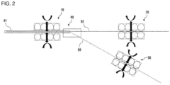
- the medical robot 1 of the inventive concept may include a first driving device 10, a second driving device 20, a third driving device 30, a first connector 40, and a support plate 50.
- the first driving device 10, the second driving device 20, and the third driving device 30 may transport the guide catheter 61, the guide wire 62, and the balloon catheter 63.
- the guide catheter 61 may be clamped to the first driving device 10
- the guide wire 62 may be clamped to the second driving device 20
- the balloon catheter 63 may be clamped to the third driving device 30.
- the first driving device 10 In order to transport the guide catheter 61, the guide wire 62 and the balloon catheter 63, the first driving device 10, the second driving device 20 and the third driving device 30 may perform "rolling operation mode", “clamping operation mode” and “vertical operation mode.
- a roller unit of each of the first driving device 10, the second driving device 20 and the third driving device 30 rotates, such that the guide catheter 61, the guide wire 62 and the balloon catheter 63 travel in a longitudinal direction.
- rollers of each of the first driving device 10, the second driving device 20 and the third driving device 30 move in the vertical direction to rotate each of the guide catheter 61, the guide wire 62 and the balloon catheter 63 having an curved end, thereby to determine a travel direction of each of the guide catheter 61, the guide wire 62 and the balloon catheter 63.
- the medical robot 1 of the inventive concept is characterized by precisely transferring the guide catheter 61, the guide wire 62 and the balloon catheter 63 using the above-described three operations.
- the roller unit is manufactured in a form of a cartridge, and may be replaced, so that surgery may be performed hygienically.
- the first driving device 10, the second driving device 20, and the third driving device 30 of the medical robot 1 of the inventive concept may have two arrangements.
- a travel direction of the first driving device 10 and a travel direction of the second driving device 20 may be in the same straight line, while the travel direction of the first driving device 10 and a travel direction of the third driving device 30 may intersect with each other.
- the first connector 40 may be used.
- the first connector 40 is disposed between the first driving device 10 and the second driving device 20 to support the guide catheter 61, the guide wire 62 and the balloon catheter 63 at the same time.
- the first connector 40 may move in the travel direction of the first driving device 10 and the second driving device 20 in order to stably support the guide catheter 61, the guide wire 62 and the balloon catheter 63.
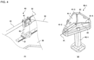
- the first connector 40 may include a first connector body 41 fixing the guide catheter 61, the guide wire 62 and the balloon catheter 63, and a first connector support 42 extending downward from the first connector body 41.
- a support plate rail 51 for guiding movement of the first connector support 42 of the first connector 40 may be formed on the support plate 50.
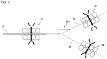
- the travel direction of the first driving device 10 and the travel direction of the second driving device 20 may intersect with each other, while the travel direction of the first driving device 10 and the travel direction of the third driving device 30 may intersect with each other, while the travel direction of the second driving device 20 and the travel direction of the third driving device 30 may intersect with each other. Furthermore, the travel direction of the first driving device 10, the travel direction of the second driving device 20, and the travel direction of the third driving device 30 may intersect with each other at a single intersection.
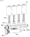
- a second connector 40-1 may be used.
- the second connector 40-1 is a "Y-shaped connector" in which the single intersection between the travel directions of the first driving device 10 and the second driving device 20 and the third driving device 30 is defined.
- the second connector 40-1 includes a second connector body 41-1 and a second connector support 42-1 extending downward from the second connector body 41-1 to support the second connector body 41-1.
- the second connector body 41-1 may include a first receiving portion 41-2 for accommodating the guide catheter 61, a second receiving portion 41-3 for accommodating the guide wire 62, and a third receiving portion 41-4 for accommodating the balloon catheter 63.
- the first receiving portion 41-2 of the second connector 40-1 may be connected with both of the second receiving portion 41-3 of the second connector 40-1 and the third receiving portion 41-4 of the second connector 40-1.
- first driving device 10 of the medical robot 1 of the inventive concept will be described with reference to the drawings.
- a configuration of the first driving device 10 may be equally applied to the second driving device 20 and the third driving device 30. That is, the first driving device 10, the second driving device 20, and the third driving device 30 may have substantially the same technical configuration.
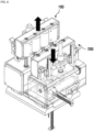
- the first driving device 10 may include a first roller module 100, a second roller module 200, and a base module 300.
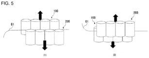
- a roller unit 110 of the first roller module 100 and a roller unit 210 of the second roller module 200 may face away each other.
- the roller unit 110 of the first roller module 100 and the roller unit 210 of the second roller module 200 respectively have rotation axes parallel to each other, and rotation directions thereof may be opposite to each other.
- the "rolling operation mode" of the first driving device 10 may be performed by rotating the roller unit 110 of the first roller module 100 and the roller unit 210 of the second roller module 200 in opposite directions to each other.
- the "clamping operation mode" of the first driving device 10 may be achieved by bringing the roller unit 110 of the first roller module 100 and the second roller unit 210 of the second roller module 200 closer to each other or moving away from each other.
- the "vertical operation mode" of the first driving device 10 may be achieved by moving the roller unit 110 of the first roller module 100 and the roller unit 210 of the second roller module 200 in opposite directions to each other in the vertical direction.
- each of the roller unit 110 of the first roller module 100 and the roller unit 210 of the second roller module 200 may be replaced in a form of a cartridge.
- first roller module 100 will be described.
- a configuration of the first roller module 100 may be equally applied to the second roller module 200.
- the first roller module 100 and the second roller module 200 may have substantially the same technical configuration.
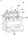
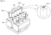
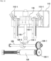
- the first roller module 100 may include the roller unit 110 and a driving unit 120.
- the roller unit 110 may include at least one roller 111 and at least one shaft 114 that may be independently coupled with the at least one roller 111 of the roller unit 110 respectively, and may be rotated by the driving unit 120.
- the at least one roller 111 of the roller unit 110 has at least one hole or groove 111-1 defined therein into which at least a portion of the at least one shaft 114 of the roller unit 110 is independently received.
- the at least one roller 111 of the roller unit 110 may be mounted to and separated from the at least one shaft 114 of the roller unit 110 while sliding in the vertical direction (a replaceable cartridge type).
- a casing 112 of the roller unit 110 together with the at least one roller 111 of the roller unit 110 may be mounted to and separated from the at least one shaft 114.
- a first hook 112-1 of the casing 112 may be locked and unlocked.
- the at least one roller 111 is rotatably coupled to the casing 112.
- the casing 112 may have at least one hole or groove defined therein corresponding to the at least one hole or groove 111-1 defined in the at least one roller 111.
- the hole or groove of the casing 112 may be defined in a bottom surface of the casing 112 and may extend upwards to a top of the casing 112. Due to this structure, the at least one roller 111 of the roller unit 110 may be mounted to and detached from the at least one shaft together with the casing while being accommodated in the casing 112 of the roller unit 110.
- the at least one hole or groove 111-1 of the at least one roller 111 of the roller unit 110 may extend in the vertical direction. Further, a horizontal cross-section of the at least one hole or groove 111-1 of the at least one roller 111 of the roller unit 110 and a horizontal cross-section of the at least one shaft 114 of the roller unit 110 may have a shape corresponding to each other.
- each of a shape of the horizontal cross-section of the at least one hole or groove 111-1 of the at least one roller 111 of the roller unit 110 and a shape of the horizontal cross-section of the at least one shaft 114 of the roller unit 110 may have a shape extending in a first direction and a second direction in a horizontal plane and intersecting with each other at a center point in a right manner.
- the roller unit 110 may rotate by the driving unit 120 in the rolling operation mode while the "vertical direction" axis is a rotation axis thereof.
- the driving unit 120 may include a first driving motor 122.
- a rotation axis of the first driving motor 122 of the driving unit 120 and a rotation axis of the at least one shaft 114 of the roller unit 110 may be perpendicular to each other.
- the driving unit 120 may further include a first driving shaft 123.
- a spur gear 122-1 of the first driving motor 122 of the driving unit 120 may mesh with a spur gear 123-1 of the first driving shaft 123 of the driving unit 120.
- At least one bevel gear 114-1 of the at least one shaft 114 of the roller unit 110 may mesh independently with at least one bevel gear 123-2 of the first driving shaft 123 of the driving unit 120.
- a driving force of the first driving motor 122 may be transmitted through the spur gear 122-1 of the first driving motor 122 and the spur gear 123-1 of the first driving shaft 123 to the first driving shaft 123. Furthermore, a driving force of the first driving shaft 123 may be transmitted through the at least one bevel gear 123-2 of the first driving shaft 123 and the bevel gear 114-1 of the at least one shaft 114 of the roller unit 110 to at least one shaft 114 of the roller unit 110.
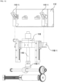
- the roller unit 110 of the first roller module 100 and the second roller unit 210 of the second roller module 200 may be moved by the base module 300 such that a spacing therebetween varies (clamping operation mode).
- the base module 300 may include a first base body 310, a first nut 340 disposed on the first base body 310 of the base module 300, and coupled to the first roller module 100, a second nut 350 disposed on the first base body 310 of the base module 300 and coupled to the second roller module 200, a screw 330 meshing with the first nut 340 of the base module 300 and the second nut 350 of the base module 300, and a first driving motor 320 to rotate the screw 330 of the base module 300.
- a gearbox 330-1 may be disposed between the first driving motor 320 of the base module 300 and the screw 330 of the base module 300, so that a rotational speed and a torque of the screw 330 of the base module 300 may be adjusted.
- the screw 330 of the base module 300 and the first nut 340 of the base module 300 and the second nut 350 of the base module 300 may operate in a "lead screw” or "ball screw” manner. That is, when the screw 330 of the base module 300 rotates, the first nut 340 of the base module 300 and the second nut 350 of the base module 300 may move along the screw 330 of the base module 300.
- a forward or reverse rotation of the screw 330 of the base module 300 may move the first nut 340 of the base module 300 and the second nut 350 of the base module 300 such that a spacing between the first roller module 100 and the second roller module 200 varies.
- a spiral rotation direction 330-2 in which the screw 330 of the base module 300 and the first nut 340 of the base module 300 mesh with each other, and a spiral rotation direction 330-3 in which the screw 330 of the base module 300 and the second nut 350 of the base module 300 mesh with each other may be opposite to each other (see (1) in FIG. 11 ).
- the base module 300 may further include a second driving motor 320-1, and a belt 320-4 connecting a spur gear 320-2 of the first driving motor 320 of the base module 300 and a spur gear 320-3 of the second driving motor 320-1 of the base module 300 to each other.
- the rotation of the first driving motor 320 of the base module 300 and the rotation of the second driving motor 320-1 of the base module 300 may be associated with each other via the belt 320-4 of the base module 300 (see (2) in FIG. 11 ).
- the roller unit 110 may move in the "vertical direction” by the driving unit 120 (vertical operation mode).
- the roller unit 110 may further include a screw 115, a nut 116 meshing with the screw 115 of the roller unit 110, and the casing 112 disposed on the nut 116 of the roller unit 110.
- the screw 115 of the roller unit 110 may be rotated by the driving unit 120, and the nut 116 of the roller unit 110 may be moved in the vertical direction by the rotation of the screw 115 of the roller unit 110.
- the screw 115 of the roller unit 110 and the nut 116 of the roller unit 110 may operate in the "lead screw” or “ball screw” manner. That is, the rotation of the screw 115 of the roller unit 110 may allow the nut 116 of the roller unit 110 to move along the screw 115 of the roller unit 110.
- the casing 112 of the roller unit 110 may be moved vertically by the nut 116 of the roller unit 110. Furthermore, the at least one roller 111 of the roller unit 110 may move in a vertical direction together with the casing 112 of the roller unit 110.
- the casing 112 of the roller unit 110 may include a pivoting hook 112-1.
- the nut 116 of the roller unit 110 may include a bar 116-1 that is locked and unlocked by the hook 112-1 of the casing 112 (see FIG. 13 ).
- the number of the hooks 112-1 of the casing 112 of the roller unit 110 may be two which may be disposed at both ends of the bar 116-1 of the nut 116, respectively.
- the driving unit 120 may include a second driving motor 124.
- the rotation axis of the second driving motor 124 of the driving unit 120 and the rotation axis of the screw 115 of the roller unit 110 may be perpendicular to each other.
- the driving unit 120 may further include a second driving shaft 125.
- a spur gear 124-1 of the second driving motor 124 of the driving unit 120 may mesh with a spur gear 125-1 of the second driving shaft 125 of the driving unit 120.
- a bevel gear 115-1 of the screw 115 of the roller unit 110 may mesh with a bevel gear 125-2 of the second driving shaft 125 of the driving unit 120.
- the driving force of the second driving motor 124 may be transmitted through the spur gear 124-1 of the second driving motor 124 and the spur gear 125-1 of the second driving shaft 125 to the second driving shaft 125. Furthermore, the driving force of the second driving shaft 125 may be transmitted through the bevel gear 125-2 of the second driving shaft 125 and the bevel gear 115-1 of the screw 115 of the roller unit 110 to the screw 115 of the roller unit 110.
- the driving unit 120 may include a box-shaped housing 121.
- the first driving motor 122, the first driving shaft 123, the second driving motor 124, and the second driving shaft 125 may be disposed inside the housing 121 of the driving unit 120.
- a lower portion of the at least one shaft 114 of the roller unit 110 may be disposed inside the housing 121 of the driving unit 120.
- the housing 121 of the driving unit 120 is supported by the first nut 340 of the base module 300.
- the driving unit 120 and the roller unit 110 may be guided and moved by the first nut 340.
Landscapes
- Health & Medical Sciences (AREA)
- Engineering & Computer Science (AREA)
- Life Sciences & Earth Sciences (AREA)
- Heart & Thoracic Surgery (AREA)
- Surgery (AREA)
- Biomedical Technology (AREA)
- Public Health (AREA)
- Veterinary Medicine (AREA)
- Animal Behavior & Ethology (AREA)
- General Health & Medical Sciences (AREA)
- Molecular Biology (AREA)
- Medical Informatics (AREA)
- Robotics (AREA)
- Nuclear Medicine, Radiotherapy & Molecular Imaging (AREA)
- General Engineering & Computer Science (AREA)
- Hematology (AREA)
- Anesthesiology (AREA)
- Pulmonology (AREA)
- Biophysics (AREA)
- Mechanical Engineering (AREA)
- Child & Adolescent Psychology (AREA)
- Manipulator (AREA)
Applications Claiming Priority (3)
| Application Number | Priority Date | Filing Date | Title |
|---|---|---|---|
| KR1020180045379A KR102184889B1 (ko) | 2018-04-19 | 2018-04-19 | 의료 로봇용 롤러 모듈, 의료 로봇용 구동 기기 및 의료 로봇 |
| PCT/KR2019/004770 WO2019203616A1 (ko) | 2018-04-19 | 2019-04-19 | 의료 로봇용 롤러 모듈, 의료 로봇용 구동 기기 및 의료 로봇 |
| EP19789507.1A EP3782574B1 (de) | 2018-04-19 | 2019-04-19 | Rollenmodul für medizinischen roboter, antriebsvorrichtung für medizinischen roboter und medizinischer roboter |
Related Parent Applications (1)
| Application Number | Title | Priority Date | Filing Date |
|---|---|---|---|
| EP19789507.1A Division EP3782574B1 (de) | 2018-04-19 | 2019-04-19 | Rollenmodul für medizinischen roboter, antriebsvorrichtung für medizinischen roboter und medizinischer roboter |
Publications (3)
| Publication Number | Publication Date |
|---|---|
| EP4233770A2 true EP4233770A2 (de) | 2023-08-30 |
| EP4233770A3 EP4233770A3 (de) | 2023-11-01 |
| EP4233770B1 EP4233770B1 (de) | 2025-12-17 |
Family
ID=68239660
Family Applications (2)
| Application Number | Title | Priority Date | Filing Date |
|---|---|---|---|
| EP23179538.6A Active EP4233770B1 (de) | 2018-04-19 | 2019-04-19 | Rollenmodul für medizinischen roboter, antriebsvorrichtung für medizinischen roboter und medizinischer roboter |
| EP19789507.1A Active EP3782574B1 (de) | 2018-04-19 | 2019-04-19 | Rollenmodul für medizinischen roboter, antriebsvorrichtung für medizinischen roboter und medizinischer roboter |
Family Applications After (1)
| Application Number | Title | Priority Date | Filing Date |
|---|---|---|---|
| EP19789507.1A Active EP3782574B1 (de) | 2018-04-19 | 2019-04-19 | Rollenmodul für medizinischen roboter, antriebsvorrichtung für medizinischen roboter und medizinischer roboter |
Country Status (7)
| Country | Link |
|---|---|
| US (2) | US12114938B2 (de) |
| EP (2) | EP4233770B1 (de) |
| KR (1) | KR102184889B1 (de) |
| CN (3) | CN119655895A (de) |
| ES (1) | ES2957400T3 (de) |
| HU (1) | HUE063058T2 (de) |
| WO (1) | WO2019203616A1 (de) |
Families Citing this family (29)
| Publication number | Priority date | Publication date | Assignee | Title |
|---|---|---|---|---|
| JP7724214B2 (ja) | 2019-11-28 | 2025-08-15 | マイクロボット メディカル リミテッド | 外科用ツールハンドルのロボット操作 |
| KR102487735B1 (ko) * | 2020-10-30 | 2023-01-12 | 주식회사 메디픽셀 | 시술도구 구동 시스템 |
| KR102511036B1 (ko) * | 2020-11-18 | 2023-03-17 | 재단법인 아산사회복지재단 | 시술 도구 제어 장치 |
| JP7555637B2 (ja) * | 2020-11-18 | 2024-09-25 | エルエヌ ロボティクス インコーポレイテッド | 施術道具制御装置 |
| KR102440299B1 (ko) | 2021-01-19 | 2022-09-05 | 주식회사 페라자 | 선 접촉 롤러 메커니즘을 가지는 혈관중재시술로봇 및 혈관중재시술시스템 |
| FR3119534B1 (fr) * | 2021-02-08 | 2024-07-05 | Robocath | dispositif de convergence entre plusieurs pistes dans un robot catheter |
| CN113509302A (zh) * | 2021-02-26 | 2021-10-19 | 中国科学院自动化研究所 | 介入手术递送装置及递送系统 |
| CN113082463A (zh) * | 2021-04-14 | 2021-07-09 | 王利 | 旋转推送装置及介入手术机器人 |
| CA3215568A1 (en) * | 2021-04-19 | 2022-10-27 | Simon Sharon | Compact robotic device and assemblies for manipulation of elongate surgical tools |
| KR102602721B1 (ko) | 2021-06-04 | 2023-11-16 | 주식회사 로엔서지컬 | 유연 수술도구의 버클링 방지 장치 |
| CN113317878B (zh) * | 2021-06-21 | 2022-06-10 | 哈尔滨理工大学 | 一种电生理导管机器人 |
| JP7540118B6 (ja) * | 2021-07-05 | 2024-09-12 | 深▲せん▼愛博合創医療机器人有限公司 | 介入手術ロボットスレーブ装置 |
| CN113729956B (zh) * | 2021-07-05 | 2023-04-28 | 深圳市爱博医疗机器人有限公司 | 一种介入手术机器人从端装置 |
| KR102386014B1 (ko) * | 2021-07-26 | 2022-04-14 | 주식회사 메디픽셀 | 텐셔너 모듈 및 이를 포함하는 스텐트 구동 장치 |
| JP2024527955A (ja) * | 2021-07-29 | 2024-07-26 | マイクロボット メディカル リミテッド | 細長い手術ツールのロボットの操作のためのマルチユニット装置 |
| FR3127111B1 (fr) * | 2021-09-17 | 2023-09-29 | Robocath | Module d’entrainement en translation de plusieurs instruments medicaux souples allonges comprenant un dispositif de convergence vers une piste commune |
| KR102416826B1 (ko) * | 2021-10-28 | 2022-07-05 | 주식회사 메디픽셀 | 길이 방향 부재를 회전시키기 위한 장치 |
| KR102697428B1 (ko) * | 2022-03-04 | 2024-08-22 | 재단법인 아산사회복지재단 | 시술 도구 제어 장치 |
| CN116269791B (zh) * | 2022-09-08 | 2025-09-09 | 北京唯迈医疗设备有限公司 | 一种便捷消毒的血管造影介入手术系统 |
| KR102892064B1 (ko) | 2022-10-20 | 2025-12-01 | (주)엘엔로보틱스 | 시술 도구 제어 장치에 연결되는 커넥터 마운터 |
| CN120018826A (zh) | 2022-10-20 | 2025-05-16 | Ln 机器人股份有限公司 | 连接到手术工具控制装置的连接器固定件 |
| WO2024085638A1 (ko) | 2022-10-20 | 2024-04-25 | (주)엘엔로보틱스 | 시술 도구 제어 장치에 연결되는 시술 도구 가이드 |
| WO2024106869A1 (ko) * | 2022-11-14 | 2024-05-23 | (주)엘엔로보틱스 | 조작 핸들을 포함하는 시술 도구 제어 시스템 |
| KR102561899B1 (ko) * | 2022-12-02 | 2023-08-01 | 주식회사 메디픽셀 | 시술도구 제어 장치 |
| KR102892073B1 (ko) | 2023-02-14 | 2025-12-01 | (주)엘엔로보틱스 | 시술 도구 제어 시스템 |
| KR102892071B1 (ko) | 2023-02-14 | 2025-12-01 | (주)엘엔로보틱스 | 시술 도구 제어 시스템 |
| CN116440392B (zh) * | 2023-03-07 | 2024-04-05 | 极限人工智能有限公司 | 基于麦克纳姆轮的导丝驱动装置、方法及介入手术机器人 |
| CN221932130U (zh) * | 2024-01-25 | 2024-11-01 | 北京万思医疗器械有限公司 | 介入耗材递送装置及血管介入手术机器人 |
| WO2025264086A1 (ko) * | 2024-06-20 | 2025-12-26 | (주)엘엔로보틱스 | 가이드 카테터 구동 장치 및 이를 포함하는 시술 도구 제어 시스템 |
Family Cites Families (20)
| Publication number | Priority date | Publication date | Assignee | Title |
|---|---|---|---|---|
| US6096004A (en) * | 1998-07-10 | 2000-08-01 | Mitsubishi Electric Information Technology Center America, Inc. (Ita) | Master/slave system for the manipulation of tubular medical tools |
| EP1442720A1 (de) * | 2003-01-31 | 2004-08-04 | Tre Esse Progettazione Biomedica S.r.l | Gerät zum Manövrieren flexibler Katheter im menschlichen kardiovaskulären System |
| US20080064920A1 (en) * | 2006-09-08 | 2008-03-13 | Ethicon Endo-Surgery, Inc. | Medical drive system for providing motion to at least a portion of a medical apparatus |
| EP3646917B1 (de) * | 2008-05-06 | 2021-04-28 | Corindus, Inc | Kathetersystem |
| CN102596306B (zh) * | 2009-11-12 | 2014-06-25 | 皇家飞利浦电子股份有限公司 | 操控系统及导管系统 |
| KR101133268B1 (ko) | 2009-11-25 | 2012-04-06 | 고려대학교 산학협력단 | 카테터 원격 제어 시스템 |
| US20130035537A1 (en) * | 2011-08-05 | 2013-02-07 | Wallace Daniel T | Robotic systems and methods for treating tissue |
| FR2999939B1 (fr) * | 2012-12-21 | 2015-01-16 | Robocath | Module d'entrainement de systeme de catheterisme |
| CN103157170B (zh) * | 2013-02-25 | 2014-12-03 | 中国科学院自动化研究所 | 一种基于两点夹持的血管介入手术导管或导丝操纵装置 |
| FR3002851B1 (fr) * | 2013-03-07 | 2015-06-19 | Robocath | Module d'entrainement de systeme de catheterisme robotise. |
| FR3022147B1 (fr) * | 2014-06-12 | 2016-07-22 | Robocath | Module robotise d'entrainement d'organe medical souple allonge |
| CN104644270B (zh) * | 2015-02-05 | 2016-09-07 | 北京航空航天大学 | 一种基于反向丝杠的导管操纵装置 |
| KR101712733B1 (ko) * | 2015-06-23 | 2017-03-06 | 한양대학교 에리카산학협력단 | 혈관중재시술로봇 및 혈관중재시술시스템 |
| WO2017010231A1 (ja) * | 2015-07-16 | 2017-01-19 | 国立大学法人名古屋大学 | 線状体の挿入駆動装置およびそれを備える医療機器、医療操作訓練装置 |
| FR3046543B1 (fr) * | 2016-01-07 | 2018-02-02 | Robocath | Module robotisable d'entrainement d'un organe medical souple allonge, robot medical et systeme comprenant un tel module |
| CA3004201C (en) * | 2016-02-05 | 2023-01-10 | Board Of Regents Of The University Of Texas System | Steerable intra-luminal medical device |
| CN105662586B (zh) * | 2016-03-03 | 2017-12-12 | 北京理工大学 | 一种导管导丝协同推送的介入手术机器人及其控制方法 |
| FR3048888A1 (fr) * | 2016-03-18 | 2017-09-22 | Robocath | Robot d'insertion d'instrument medical souple allonge et accessoires associes |
| CN106880380A (zh) * | 2017-03-21 | 2017-06-23 | 上海大学 | 血管介入手术导丝导管操作装置 |
| JP6827130B2 (ja) * | 2017-12-29 | 2021-02-10 | エックスキャス, インコーポレイテッド | 操向可能外科ロボティックシステム |
-
2018
- 2018-04-19 KR KR1020180045379A patent/KR102184889B1/ko active Active
-
2019
- 2019-04-19 CN CN202510085000.4A patent/CN119655895A/zh active Pending
- 2019-04-19 CN CN202510084843.2A patent/CN119655894A/zh active Pending
- 2019-04-19 CN CN201980026784.6A patent/CN111989064B/zh active Active
- 2019-04-19 HU HUE19789507A patent/HUE063058T2/hu unknown
- 2019-04-19 EP EP23179538.6A patent/EP4233770B1/de active Active
- 2019-04-19 WO PCT/KR2019/004770 patent/WO2019203616A1/ko not_active Ceased
- 2019-04-19 ES ES19789507T patent/ES2957400T3/es active Active
- 2019-04-19 EP EP19789507.1A patent/EP3782574B1/de active Active
-
2020
- 2020-10-16 US US17/072,912 patent/US12114938B2/en active Active
-
2024
- 2024-09-10 US US18/829,767 patent/US20240423729A1/en active Pending
Also Published As
| Publication number | Publication date |
|---|---|
| CN111989064B (zh) | 2025-02-14 |
| EP3782574B1 (de) | 2023-07-12 |
| EP3782574A4 (de) | 2022-01-26 |
| CN119655894A (zh) | 2025-03-21 |
| US12114938B2 (en) | 2024-10-15 |
| US20210052339A1 (en) | 2021-02-25 |
| ES2957400T3 (es) | 2024-01-18 |
| EP3782574A1 (de) | 2021-02-24 |
| EP4233770A3 (de) | 2023-11-01 |
| CN119655895A (zh) | 2025-03-21 |
| EP4233770B1 (de) | 2025-12-17 |
| KR102184889B1 (ko) | 2020-12-01 |
| KR102184889B9 (ko) | 2022-03-15 |
| WO2019203616A1 (ko) | 2019-10-24 |
| HUE063058T2 (hu) | 2023-12-28 |
| CN111989064A (zh) | 2020-11-24 |
| KR20190121928A (ko) | 2019-10-29 |
| US20240423729A1 (en) | 2024-12-26 |
Similar Documents
| Publication | Publication Date | Title |
|---|---|---|
| EP3782574B1 (de) | Rollenmodul für medizinischen roboter, antriebsvorrichtung für medizinischen roboter und medizinischer roboter | |
| JP7404501B2 (ja) | 細長い医療デバイスの複数を用いるロボット介入処置のためのシステム、装置及び方法 | |
| US9770301B2 (en) | Module for driving a catheterization system | |
| US20250030311A1 (en) | Differential Drive | |
| US10149728B2 (en) | Elongate medical part guide module | |
| CN217488850U (zh) | 用于基于导管的手术系统的机器人驱动系统 | |
| US20040254566A1 (en) | Apparatus for the maneuvering of flexible catheters in the human cardiovascular system | |
| CN114762612B (zh) | 用于细长医疗装置的扭矩器 | |
| US20240000524A1 (en) | System and apparatus for manipulating an elongated medical device in a robotic catheter-based procedure system | |
| CN113545852A (zh) | 器械递送模块以及介入手术机器人 | |
| CN108113757B (zh) | 穿戴式血管介入手术机器人装置 | |
| EP4353181A2 (de) | Antriebsstrang für längliche medizinische vorrichtung | |
| CN118453130A (zh) | 双通道血管介入手术机器人器械递送盒组件 | |
| JP7711988B2 (ja) | 血管インターベンション施術装置 | |
| CN222657183U (zh) | 双通道血管介入手术机器人器械递送盒组件 | |
| CN221844971U (zh) | 用于细长医疗设备扭矩器的扭矩限制致动器 | |
| US20240207574A1 (en) | Torque lmiting actuator for elongated medical device torquer | |
| CN116849811A (zh) | 用于介入手术机器人的从端驱动装置 | |
| JP2024521778A (ja) | 血管インターベンション施術装置 | |
| HK40079391A (en) | Device for automatically inserting and manipulating a medical tool into and within a bodily lumen | |
| HK40078928A (en) | Modular robotic system for driving movement of surgical tools |
Legal Events
| Date | Code | Title | Description |
|---|---|---|---|
| PUAI | Public reference made under article 153(3) epc to a published international application that has entered the european phase |
Free format text: ORIGINAL CODE: 0009012 |
|
| STAA | Information on the status of an ep patent application or granted ep patent |
Free format text: STATUS: THE APPLICATION HAS BEEN PUBLISHED |
|
| AC | Divisional application: reference to earlier application |
Ref document number: 3782574 Country of ref document: EP Kind code of ref document: P |
|
| AK | Designated contracting states |
Kind code of ref document: A2 Designated state(s): AL AT BE BG CH CY CZ DE DK EE ES FI FR GB GR HR HU IE IS IT LI LT LU LV MC MK MT NL NO PL PT RO RS SE SI SK SM TR |
|
| REG | Reference to a national code |
Ref country code: DE Ref legal event code: R079 Free format text: PREVIOUS MAIN CLASS: A61B0034350000 Ipc: A61B0034300000 Ref country code: DE Ref legal event code: R079 Ref document number: 602019079461 Country of ref document: DE Free format text: PREVIOUS MAIN CLASS: A61B0034350000 Ipc: A61B0034300000 |
|
| PUAL | Search report despatched |
Free format text: ORIGINAL CODE: 0009013 |
|
| AK | Designated contracting states |
Kind code of ref document: A3 Designated state(s): AL AT BE BG CH CY CZ DE DK EE ES FI FR GB GR HR HU IE IS IT LI LT LU LV MC MK MT NL NO PL PT RO RS SE SI SK SM TR |
|
| RIC1 | Information provided on ipc code assigned before grant |
Ipc: A61B 34/35 20160101ALI20230925BHEP Ipc: A61B 17/00 20060101ALI20230925BHEP Ipc: A61M 25/09 20060101ALI20230925BHEP Ipc: A61M 25/01 20060101ALI20230925BHEP Ipc: A61B 34/20 20160101ALI20230925BHEP Ipc: A61B 34/30 20160101AFI20230925BHEP |
|
| STAA | Information on the status of an ep patent application or granted ep patent |
Free format text: STATUS: REQUEST FOR EXAMINATION WAS MADE |
|
| 17P | Request for examination filed |
Effective date: 20240426 |
|
| RBV | Designated contracting states (corrected) |
Designated state(s): AL AT BE BG CH CY CZ DE DK EE ES FI FR GB GR HR HU IE IS IT LI LT LU LV MC MK MT NL NO PL PT RO RS SE SI SK SM TR |
|
| GRAP | Despatch of communication of intention to grant a patent |
Free format text: ORIGINAL CODE: EPIDOSNIGR1 |
|
| STAA | Information on the status of an ep patent application or granted ep patent |
Free format text: STATUS: GRANT OF PATENT IS INTENDED |
|
| INTG | Intention to grant announced |
Effective date: 20250717 |
|
| GRAS | Grant fee paid |
Free format text: ORIGINAL CODE: EPIDOSNIGR3 |
|
| GRAA | (expected) grant |
Free format text: ORIGINAL CODE: 0009210 |
|
| STAA | Information on the status of an ep patent application or granted ep patent |
Free format text: STATUS: THE PATENT HAS BEEN GRANTED |
|
| AC | Divisional application: reference to earlier application |
Ref document number: 3782574 Country of ref document: EP Kind code of ref document: P |
|
| AK | Designated contracting states |
Kind code of ref document: B1 Designated state(s): AL AT BE BG CH CY CZ DE DK EE ES FI FR GB GR HR HU IE IS IT LI LT LU LV MC MK MT NL NO PL PT RO RS SE SI SK SM TR |
|
| REG | Reference to a national code |
Ref country code: CH Ref legal event code: F10 Free format text: ST27 STATUS EVENT CODE: U-0-0-F10-F00 (AS PROVIDED BY THE NATIONAL OFFICE) Effective date: 20251217 Ref country code: GB Ref legal event code: FG4D |
|
| REG | Reference to a national code |
Ref country code: DE Ref legal event code: R096 Ref document number: 602019079461 Country of ref document: DE |
|
| P01 | Opt-out of the competence of the unified patent court (upc) registered |
Free format text: CASE NUMBER: UPC_APP_0019160_4233770/2025 Effective date: 20251223 |