EP4219968B1 - Schrägkugellager - Google Patents
Schrägkugellager Download PDFInfo
- Publication number
- EP4219968B1 EP4219968B1 EP21872301.3A EP21872301A EP4219968B1 EP 4219968 B1 EP4219968 B1 EP 4219968B1 EP 21872301 A EP21872301 A EP 21872301A EP 4219968 B1 EP4219968 B1 EP 4219968B1
- Authority
- EP
- European Patent Office
- Prior art keywords
- inner ring
- raceway groove
- mass
- outer ring
- ring raceway
- Prior art date
- Legal status (The legal status is an assumption and is not a legal conclusion. Google has not performed a legal analysis and makes no representation as to the accuracy of the status listed.)
- Active
Links
Images





Classifications
-
- F—MECHANICAL ENGINEERING; LIGHTING; HEATING; WEAPONS; BLASTING
- F16—ENGINEERING ELEMENTS AND UNITS; GENERAL MEASURES FOR PRODUCING AND MAINTAINING EFFECTIVE FUNCTIONING OF MACHINES OR INSTALLATIONS; THERMAL INSULATION IN GENERAL
- F16C—SHAFTS; FLEXIBLE SHAFTS; ELEMENTS OR CRANKSHAFT MECHANISMS; ROTARY BODIES OTHER THAN GEARING ELEMENTS; BEARINGS
- F16C19/00—Bearings with rolling contact, for exclusively rotary movement
- F16C19/02—Bearings with rolling contact, for exclusively rotary movement with bearing balls essentially of the same size in one or more circular rows
- F16C19/14—Bearings with rolling contact, for exclusively rotary movement with bearing balls essentially of the same size in one or more circular rows for both radial and axial load
- F16C19/16—Bearings with rolling contact, for exclusively rotary movement with bearing balls essentially of the same size in one or more circular rows for both radial and axial load with a single row of balls
- F16C19/163—Bearings with rolling contact, for exclusively rotary movement with bearing balls essentially of the same size in one or more circular rows for both radial and axial load with a single row of balls with angular contact
-
- F—MECHANICAL ENGINEERING; LIGHTING; HEATING; WEAPONS; BLASTING
- F16—ENGINEERING ELEMENTS AND UNITS; GENERAL MEASURES FOR PRODUCING AND MAINTAINING EFFECTIVE FUNCTIONING OF MACHINES OR INSTALLATIONS; THERMAL INSULATION IN GENERAL
- F16C—SHAFTS; FLEXIBLE SHAFTS; ELEMENTS OR CRANKSHAFT MECHANISMS; ROTARY BODIES OTHER THAN GEARING ELEMENTS; BEARINGS
- F16C19/00—Bearings with rolling contact, for exclusively rotary movement
- F16C19/02—Bearings with rolling contact, for exclusively rotary movement with bearing balls essentially of the same size in one or more circular rows
- F16C19/14—Bearings with rolling contact, for exclusively rotary movement with bearing balls essentially of the same size in one or more circular rows for both radial and axial load
- F16C19/16—Bearings with rolling contact, for exclusively rotary movement with bearing balls essentially of the same size in one or more circular rows for both radial and axial load with a single row of balls
-
- F—MECHANICAL ENGINEERING; LIGHTING; HEATING; WEAPONS; BLASTING
- F16—ENGINEERING ELEMENTS AND UNITS; GENERAL MEASURES FOR PRODUCING AND MAINTAINING EFFECTIVE FUNCTIONING OF MACHINES OR INSTALLATIONS; THERMAL INSULATION IN GENERAL
- F16C—SHAFTS; FLEXIBLE SHAFTS; ELEMENTS OR CRANKSHAFT MECHANISMS; ROTARY BODIES OTHER THAN GEARING ELEMENTS; BEARINGS
- F16C33/00—Parts of bearings; Special methods for making bearings or parts thereof
- F16C33/30—Parts of ball or roller bearings
- F16C33/58—Raceways; Race rings
-
- F—MECHANICAL ENGINEERING; LIGHTING; HEATING; WEAPONS; BLASTING
- F16—ENGINEERING ELEMENTS AND UNITS; GENERAL MEASURES FOR PRODUCING AND MAINTAINING EFFECTIVE FUNCTIONING OF MACHINES OR INSTALLATIONS; THERMAL INSULATION IN GENERAL
- F16C—SHAFTS; FLEXIBLE SHAFTS; ELEMENTS OR CRANKSHAFT MECHANISMS; ROTARY BODIES OTHER THAN GEARING ELEMENTS; BEARINGS
- F16C33/00—Parts of bearings; Special methods for making bearings or parts thereof
- F16C33/30—Parts of ball or roller bearings
- F16C33/58—Raceways; Race rings
- F16C33/583—Details of specific parts of races
- F16C33/585—Details of specific parts of races of raceways, e.g. ribs to guide the rollers
-
- F—MECHANICAL ENGINEERING; LIGHTING; HEATING; WEAPONS; BLASTING
- F16—ENGINEERING ELEMENTS AND UNITS; GENERAL MEASURES FOR PRODUCING AND MAINTAINING EFFECTIVE FUNCTIONING OF MACHINES OR INSTALLATIONS; THERMAL INSULATION IN GENERAL
- F16C—SHAFTS; FLEXIBLE SHAFTS; ELEMENTS OR CRANKSHAFT MECHANISMS; ROTARY BODIES OTHER THAN GEARING ELEMENTS; BEARINGS
- F16C2240/00—Specified values or numerical ranges of parameters; Relations between them
- F16C2240/12—Force, load, stress, pressure
- F16C2240/18—Stress
-
- F—MECHANICAL ENGINEERING; LIGHTING; HEATING; WEAPONS; BLASTING
- F16—ENGINEERING ELEMENTS AND UNITS; GENERAL MEASURES FOR PRODUCING AND MAINTAINING EFFECTIVE FUNCTIONING OF MACHINES OR INSTALLATIONS; THERMAL INSULATION IN GENERAL
- F16C—SHAFTS; FLEXIBLE SHAFTS; ELEMENTS OR CRANKSHAFT MECHANISMS; ROTARY BODIES OTHER THAN GEARING ELEMENTS; BEARINGS
- F16C2240/00—Specified values or numerical ranges of parameters; Relations between them
- F16C2240/40—Linear dimensions, e.g. length, radius, thickness, gap
- F16C2240/70—Diameters; Radii
-
- Y—GENERAL TAGGING OF NEW TECHNOLOGICAL DEVELOPMENTS; GENERAL TAGGING OF CROSS-SECTIONAL TECHNOLOGIES SPANNING OVER SEVERAL SECTIONS OF THE IPC; TECHNICAL SUBJECTS COVERED BY FORMER USPC CROSS-REFERENCE ART COLLECTIONS [XRACs] AND DIGESTS
- Y02—TECHNOLOGIES OR APPLICATIONS FOR MITIGATION OR ADAPTATION AGAINST CLIMATE CHANGE
- Y02T—CLIMATE CHANGE MITIGATION TECHNOLOGIES RELATED TO TRANSPORTATION
- Y02T10/00—Road transport of goods or passengers
- Y02T10/80—Technologies aiming to reduce greenhouse gasses emissions common to all road transportation technologies
- Y02T10/86—Optimisation of rolling resistance, e.g. weight reduction
Definitions
- the present invention relates to an angular ball bearing, and particularly to a ball bearing used for various machine tool spindles, motors, and the like.
- the viscosity of the oil may decrease, an oil film may break at a rolling contact portion between the ball and a bearing ring, the bearing may be seized, the thermal displacement of the spindle may increase, and the machining accuracy may deteriorate.
- Patent Literature 1 As a related-art technique for reducing the heat generation amount of the angular ball bearing, for example, a technique (see Patent Literature 1) in which the groove curvature radius ratio of an outer ring is set to 50.5% to 53% and the groove curvature radius ratio of an inner ring is set to 52.5% to 60%, and a technique (see Patent Literature 2) in which both the groove curvature radius ratio of the outer ring and the groove curvature radius ratio of the inner ring are set to 54% to 57% are known.
- Patent Literatures 1 and 2 although the low heat generation is achieved by setting the groove curvature radius ratios of the outer ring and the inner ring to be large, the surface pressure of the contact portion between a rolling element and a raceway surface tends to be high.
- the contact portion between the rolling element and the raceway surface of the inner ring and the contact portion between the rolling element and the raceway surface of the outer ring are respectively the contact between the outer peripheral portion of a rolling element arc and the outer peripheral portion of an inner ring raceway surface arc, and the contact between the outer peripheral portion of the rolling element arc and the inner peripheral portion of an outer ring raceway surface arc.
- the contact surface pressure on the raceway surface of the inner ring tends to be particularly high. Therefore, when the external impact load is applied to the angular ball bearing in the stationary state, an indentation is likely to be generated in the inner ring raceway surface.
- the external impact load is not a machining load that is applied during the normal cutting, but is a collision load due to an unexpected interference of the spindle (including parts up to the blade) with a workpiece, a jig, and a component constituting a machine tool in a machining chamber, an unclamp load at the time of replacing the blade, and a load due to an unexpected collision during the assembly process of the spindle and the vibration and the impact that the bearing receives when transporting the bearing alone.
- the external impact load is a large load that is one digit or more larger than the machining load during operation. Therefore, when the operation is performed in a state in which an indentation is generated in the raceway surface due to the external impact load, the vibration may occur and the quality of the machined surface of the workpiece may decrease, or peeling may occur from the indentation in the raceway surface as a starting point.
- the present invention has been made in order to solve such a problem, and the object of the present invention is to provide an angular ball bearing capable of reducing the heat generation amount and capable of reducing the damage caused by the external impact load in the stationary state.
- the present invention provides an angular ball bearing described below.
- the angular ball bearing in the present invention it is possible to reduce the heat generation amount, and it is possible to reduce the damage caused by the external impact load in the stationary state.
- the angular ball bearing according to the present invention is useful as an angular ball bearing for a machine tool spindle used in the high speed rotation of dmn 800,000 or higher.
- FIG. 1 shows an angular ball bearing used for a machine tool spindle as an example of an angular ball bearing according to the present invention.
- An angular ball bearing 1 includes an inner ring 2 that has an inner ring raceway groove 2a having an arc-shaped cross section on the outer peripheral surface of the inner ring 2, an outer ring 3 that has an outer ring raceway groove 3a having an arc-shaped cross section on the inner peripheral surface of the outer ring 3, a plurality of balls 4 provided rollably between the inner ring raceway groove 2a and the outer ring raceway groove 3a, and a cage 5 that holds the plurality of balls 4.
- a counter bore 3b is formed on one side of the inner peripheral surface of the outer ring 3 in the axial direction, and the ball 4 is provided between the inner ring raceway groove 2a and the outer ring raceway groove 3a with contact angles ⁇ i and ⁇ o.
- the contact angles ⁇ i and ⁇ o are defined as angles between a plane P perpendicular to a bearing axis X and action lines.
- the action lines connect contact points where the ball 4 comes into contact with the inner ring 2 and the outer ring 3 and the center of the ball 4.
- the ball 4 has a ratio value of ball diameter/cross-sectional height, that is, diameter of the ball 4/ ⁇ (outer diameter of outer ring 3 - inner diameter of inner ring 2)/2 ⁇ of 0.39 to 0.65, preferably 0.55 to 0.65.
- Ri - Ro ⁇ 0 points preferably Ri - Ro ⁇ 1 point.
- the groove curvature radius ratio Ri of the inner ring raceway groove 2a to the ball diameter is also referred to as an inner ring groove curvature radius ratio Ri
- the groove curvature radius ratio Ro of the outer ring raceway groove 3a to the ball diameter is also referred to as an outer ring groove curvature radius ratio Ro.
- a cured surface layer 10 is formed in the inner ring raceway groove 2a by roller burnishing, which is machining, and the inner ring raceway groove 2a has a maximum surface pressure of 4.7 GPa to 6.0 GPa when the sum of the permanent deformation amounts of the ball 4 and the inner ring raceway groove 2a at the center of the contact portion between the ball 4 and the inner ring raceway groove 2a is 1/10,000 of the ball diameter.
- the outer ring raceway groove 3a is not subjected to the roller burnishing, and no cured surface layer is formed.
- the roller burnishing is performed after the inner ring raceway groove 2a of the inner ring 2 formed by cutting has been subjected to the heat treatment and the finish machining has been performed. Further, if necessary, precision machining may be performed after the roller burnishing step.
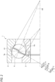
- the reference sign AX denotes the rotation axis of the ball 4 of the outer ring control.
- the contact angle ⁇ i is less likely to be increased during the high speed rotation, and the contact ellipse length can be reduced. Therefore, the heat generation due to the spin slip can be reduced. That is, as shown in FIG. 4B , when Ri is increased, the change in the contact angle due to the centrifugal force decreases, and the spin slip amount also decreases. On the other hand, as shown in FIG. 4C , when Ri is reduced, the change in the contact angle due to the centrifugal force F increases, and the spin slip amount also increases. Therefore, it is considered that it is preferable to increase Ri in order to reduce the spin slip amount.
- the angular ball bearing of the following analysis condition 1 was used to change the inner ring groove curvature radius ratio Ri and the outer ring groove curvature radius ratio Ro, and the total spin heat generation amount of the inner ring side and the outer ring side was calculated.
- the calculation result of a total spin heat generation amount (W) corresponding to Ri and Ro is shown in Table 1.
- FIG. 5 is a graph showing the relationship between the inner ring groove curvature radius ratio Ri and the total spin heat generation amount with the outer ring groove curvature radius ratio Ri as the horizontal axis
- FIG. 6 is a graph showing the relationship between the outer ring groove curvature radius ratio Ro and the total spin heat generation amount with the outer ring groove curvature radius ratio Ro as the horizontal axis.
- the inner ring groove curvature radius ratio Ri is set to 54% to 58%.
- the outer ring groove curvature radius ratio Ro when the outer ring groove curvature radius ratio Ro is less than 51%, the heat generation amount is extremely large, and the minimum value is taken around 52%.
- the outer ring groove curvature radius ratio Ro is equal to or larger than 52%, the increase in the heat generation amount due to the increase in Ro is relatively gentle.
- the variation in the heat generation amount due to the variation in the final quality of Ri during manufacturing can be controlled to be small if a region slightly larger than the minimum value of 52% is targeted.
- the outer ring groove curvature radius ratio Ro is 58%, a value substantially equal to 51% is taken. Therefore, from the viewpoint of the effect of reducing the spin heat generation amount, the outer ring groove curvature radius ratio Ro is set to 51% to 58% including the minimum value of the heat generation amount.
- the roller burnishing processing is applied to the raceway groove.
- the hydraulically held ceramic or cemented carbide ball (the indenter) is pressed against the inner ring raceway groove 2a and is moved along the axial cross section of the inner ring raceway groove 2a while being in rolling contact with the inner ring raceway groove 2a.
- the surface is cured by this roller burnishing processing.
- the machining conditions such as the indenter diameter and the pressing force of the burnishing tool are selected such that the maximum surface pressure is 4.7 GPa to 6.0 GPa when the sum of the permanent deformation amounts of the ball 4 and the inner ring raceway groove 2a at the center of the contact portion between the ball 4 and the inner ring raceway groove 2a is 1/10,000 of the ball diameter.
- the sum of the permanent deformation amount of the ball 4 and the permanent deformation amount of the raceway at the center of the contact portion between the ball 4 and the raceway is set to 1/10,000 of the ball diameter.
- the maximum surface pressure is 4.2 GPa when the sum of the permanent deformation amounts of the ball and the raceway groove at the center of the contact portion between the ball and the raceway groove is 1/10,000 of the ball diameter (JIS B1519 compliant). Therefore, by applying the residual compressive stress, it is possible to attain the effect that the indentation is less likely to be generated due to the external impact load in the stationary state.
- the surface pressure of approximately 4 GPa or more is applied to the bearing returned from the market as being hit-damaged.
- the maximum surface pressure is 4.7 GPa when the sum of the permanent deformation amounts of the ball 4 and the inner ring raceway groove 2a is 1/10,000 of the ball diameter
- the defective product due to the indentation generated at the surface pressure of approximately 4 GPa or more and less than 4.7 GPa is no longer recognized as defective. Accordingly, the trouble of replacing the bearing is eliminated.
- the maximum surface pressure is set to 4.7 GPa to 6.0 GPa when the sum of the permanent deformation amounts of the ball 4 and the inner ring raceway groove 2a is 1/10,000 of the ball diameter.
- the cured surface layer is not limited to being applied to the inner ring raceway groove 2a of the inner ring 2, and may be applied to the outer ring raceway groove 3a of the outer ring 3.
- Patent Literature 1 The technique for forming a hard film having the thickness of 0.05 ⁇ m to 8 ⁇ m on the raceway surface disclosed in Patent Literature 1 is a technique in which the cured layer is coated on the bearing ring after machining by a chemical treatment to improve the wear resistance and reduce the friction coefficient.
- the surface-machined layer 10 according to the present embodiment the surface is cured by machining, and the indentation resistance is improved.
- the inner ring groove curvature radius ratio Ri and the outer ring groove curvature radius ratio Ro are set within the above-described ranges. However, by setting Ri to be equal to or larger than the outer ring groove curvature radius ratio Ro, the increase in the surface pressure of the outer ring 3 when the load is applied is controlled to be lower than that of the inner ring 2. On the other hand, the cured surface layer 10 is formed in the inner ring raceway groove 2a.
- the maximum surface pressure is set within the above-described range when the sum of the permanent deformation amounts of the ball 4 and the inner ring raceway groove 2a is 1/10,000 of the ball diameter in the inner ring raceway groove 2a. Accordingly, the effect of improving the indentation resistance can be sufficiently attained.
- the maximum surface pressure is set to 4.7 GPa to 6.0 GPa when the sum of the permanent deformation amounts of the ball 4 and the inner ring raceway groove 2a is 1/10,000 of the ball diameter, and the surface curing processing is not performed on the outer ring raceway groove of the outer ring, the ratio of the inner ring surface pressure to the outer ring surface pressure, in which the indentation is generated on the inner ring raceway surface before the outer ring raceway surface, is in the region of 1.120 ⁇ inner ring surface pressure/outer ring surface pressure ⁇ 1.429 shown in FIG. 7 .
- the total spin heat generation amount can be reduced by setting the inner ring groove curvature radius ratio Ri to 54% to 58% and the outer ring groove curvature radius ratio Ro to 51% to 58% when the ball diameter/cross-sectional height ratio is 0.595 using the ball having the relatively large ball diameter (the large ball).
- an analysis condition 2 it was checked whether the total spin heat generation amount can be reduced according to the above-described definitions of Ri and Ro when the ball diameter/cross-sectional height ratio is 0.437 using the ball having the smaller ball diameter (the small ball) than the above.
- the calculation result of the total spin heat generation amount (W) corresponding to Ri and Ro is shown in Table 2.
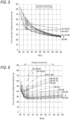
- FIG. 8 is a graph showing the relationship between the inner ring groove curvature radius ratio Ri and the total spin heat generation amount with the outer ring groove curvature radius ratio Ri as the horizontal axis
- FIG. 9 is a graph showing the relationship between the outer ring groove curvature radius ratio Ro and the total spin heat generation amount on the inner ring side and the outer ring side with the outer ring groove curvature radius ratio Ro as the horizontal axis.
- the effect of reducing the total spin heat generation amount on the inner ring side and the outer ring side is recognized in the range where the inner ring groove curvature radius ratio Ri is 54% to 58% and the outer ring groove curvature radius ratio Ro is 51% to 58%.
- FIG. 10 is a graph showing the relationship between the inner ring groove curvature radius ratio Ri and the total spin heat generation amount with the outer ring groove curvature radius ratio Ri as the horizontal axis in the analysis condition 3
- FIG. 11 is a graph showing the relationship between the outer ring groove curvature radius ratio Ro and the total spin heat generation amount with the outer ring groove curvature radius ratio Ro as the horizontal axis in the analysis condition 3.
- FIG. 12 is a graph showing the relationship between the inner ring groove curvature radius ratio Ri and the total spin heat generation amount with the outer ring groove curvature radius ratio Ri as the horizontal axis in the analysis condition 4
- FIG. 13 is a graph showing the relationship between the outer ring groove curvature radius ratio Ro and the total spin heat generation amount with the outer ring groove curvature radius ratio Ro as the horizontal axis in the analysis condition 4.
- the effect of reducing the total spin heat generation amount on the inner ring side and the outer ring side is recognized in the range where the inner ring groove curvature radius ratio Ri is 54% to 58% and the outer ring groove curvature radius ratio Ro is 51% to 58%.
- the smaller the ball diameter/cross-sectional height ratio the more advantageous it is in reducing the heat generation.
- the ball diameter/cross-sectional height ratio needs to be 0.39 or more.
- the larger the ball diameter/cross-sectional height ratio the more advantageous it is for the indentation resistance.
- the ratio value of ball diameter/cross-sectional height is 0.39 to 0.65, and it is more preferable to use the large ball having the ratio value of ball diameter/cross-sectional height of 0.55 to 0.65 when the indentation resistance is emphasized.
- the inner ring 2 and the outer ring 3 are typically formed of the bearing steel such as high carbon chromium bearing steel (SUJ2).
- the bearing steel such as SUJ2 is used at the relatively low temperature because the hardness drops remarkably and the service life is shortened at the high temperature. Therefore, when the rotation is required at the higher speed, the contact pressure on the contact surface where the ball 4 and the inner ring 2 and the outer ring 3 are in contact with each other and the slippage of the ball 4 are increased, heat is generated, and the temperature becomes locally high. Therefore, it is desirable that the inner ring 2 and the outer ring 3 are formed of a material having excellent heat resistance and wear resistance.
- the material in which the secondary curing precipitated eutectic carbide is formed for example, high-speed steel, semi-high-speed steel, or martensitic stainless steel is preferable, and the examples thereof include SKD, SKH, M50, and SUS440C.
- the general bearing steel (SUJ2) whose tempering temperature is raised to 240°C to 330°C may be used and hard-coated.
- the hardness of the base material itself decreases, since the hardness of the raceway ring surface can be increased by applying the hard coating, the same performance as in the case of using the above-described metal material can be attained.
- the material (the material similar to high carbon chromium steel) whose tempering resistance is improved by the constituent element component and whose dimension is stabilized is preferable, and the examples thereof include the SHX material.
- at least one of the inner ring 2 and the outer ring 3 is formed of the steel material containing 0.2% by mass to 1.2% by mass of C, 0.7% by mass to 1.5 % by mass of Si, 0.5% by mass to 1.5% by mass of Mo, 0.5% by mass to 2.0% by mass of Cr, the balance Fe, and unavoidable impurity elements.
- the surface carbon concentration is 0.8% by mass to 1.3% by mass and the surface nitrogen concentration is 0.2% by mass to 0.8% by mass.
- Si is an element effective in temper softening resistance, and has the effect of improving the high-temperature strength and retarding the decomposition of retained austenite, which is effective in preventing the indentation-induced flaking in the high temperature environment.
- the Si content was less than 0.7% by mass, the high temperature strength was insufficient, and the indentation-induced flaking occurred. Therefore, the lower limit value of the Si content was set to 0.7% by mass.
- the Si content was more than 1.5% by mass, the mechanical strength decreases, and carburization is inhibited. Therefore, the upper limit value of the Si content is set to 1.5% by mass.
- Cr is an additive element having the same function and effect as Mo.
- the Cr content was less than 0.5% by mass, the high temperature strength was insufficient, and the amount of the carbide precipitated on the surface was insufficient. Therefore, the lower limit value of the Cr content was set to 0.5% by mass.
- the Cr content is more than 2.0% by mass, giant carbide is formed in the raw material stage, causing the carbide to fall out and reduce the rolling fatigue life of the bearing. Therefore, the upper limit value of the Cr content was set to 2.0% by mass.
- the amount of the retained austenite is too large, the retained austenite decomposes and changes in shape over time, and the dimensional stability of the bearing is impaired.
- the presence of the retained austenite in the bearing ring surface is effective in preventing the indentation-induced flaking. Therefore, it is preferable to limit the amount of the retained austenite in the entire bearing after the retained austenite is present on the surface. Therefore, it is necessary to reduce the amount of the retained austenite in the bearing core portion. From this point of view, it is preferable that the amount of the average retained austenite in the steel including the surface and the core portion is 5% by volume or less.
- the carbon concentration on which the retained austenite depends is set to 1.2% by mass or less, and thus the upper limit value of the carbon concentration was set to 1.2% by mass.
- the carbon concentration is less than 0.2% by mass, it takes a long time to obtain the desired carburizing depth in the carbonitriding treatment, which leads to the increase in overall cost. Therefore, the lower limit value of the carbon concentration was set to 0.2% by mass.
- the martensite structure serving as the matrix can be subjected to the solid solution strengthening, and a large amount of retained austenite effective for preventing the indentation-induced flaking can be formed in the extreme surface layer portion.
- the surface carbon concentration is less than 0.8% by mass, the surface hardness is insufficient, and the rolling fatigue life and the wear resistance are lowered. Therefore, the lower limit value of the surface carbon concentration is set to 0.8% by mass.
- the surface carbon concentration is more than 1.3% by mass, giant carbide is precipitated during the carbonitriding treatment, and the rolling fatigue life is reduced. Therefore, the upper limit value of the surface carbon concentration is set to 1.3% by mass.
- the tempering resistance is improved, the high temperature strength is increased, the wear resistance is improved, and a large amount of retained austenite effective for preventing the indentation-induced flaking can be presented in the extreme surface layer portion.
- the surface nitrogen concentration is less than 0.2% by mass, the high temperature strength is lowered, and the wear resistance is lowered. Therefore, the lower limit value of the surface nitrogen concentration is set to 0.2% by mass.
- the upper limit value of the surface nitrogen concentration is set to 0.8% by mass.
- the balance is Fe and unavoidable impurities, and it is preferable to add a small amount of Ti as another constituent element.
- TiC fine titanium carbide
- Ti (C + N) carbonitride
- the Ti content is desirably 0.1% by mass to 0.3% by mass. If the Ti content is less than 0.1% by mass, the effect of the precipitation of the carbide cannot be attained, and thus the lower limit value of the Ti content is set to 0.1% by mass. On the other hand, if the Ti content is more than 0.3% by mass, the huge precipitate is likely to be formed.
- the upper limit value of the Ti content is set to 0.3% by mass.
- the size of the titanium precipitate (TiC and Ti (C + N)) is 0.1 ⁇ m or less, it contributes to the improvement of the wear resistance and the seizure resistance.
- the oxygen content is desirably less than 12 ppm.
- the ball 4 may be formed of steel excellent in heat resistance and wear resistance, and may also be formed of ceramics such as silicon nitride (Si 3 N 4 ), silicon carbide (SiC), or aluminum oxide (Al 2 O 3 ).
- ceramics such as silicon nitride (Si 3 N 4 ), silicon carbide (SiC), or aluminum oxide (Al 2 O 3 ).
- the ceramic ball 4 since the ceramic ball 4 has a Young's modulus higher than that of the steel ball, the contact pressure between the ball 4 and the raceway groove is high and the indentation tends to be generated. Therefore, the angular ball bearing having the improved indentation resistance, as in the present embodiment, operates more effectively.
- the angular ball bearing is suitable for the use in the application in which the angular ball bearing is used during the high speed rotation and the excessive load is applied in the stationary state, and is particularly useful as an angular ball bearing that is used for the machine tool spindle having the dmn of 800,000 or more and that is pre-loaded.
- the lubrication method of the angular ball bearing according to the present invention may be the oil air lubrication or the grease lubrication.
Landscapes
- Engineering & Computer Science (AREA)
- General Engineering & Computer Science (AREA)
- Mechanical Engineering (AREA)
- Rolling Contact Bearings (AREA)
Claims (9)
- Schrägkugellager, das umfasst:einen Innenring, der eine Laufbahn-Nut des Innenrings mit einem bogenförmigen Querschnitt an einer Außenumfangsfläche des Innenrings aufweist;einen Außenring, der eine Laufbahn-Nut des Außenrings mit einem bogenförmigen Querschnitt an einer Innenumfangsfläche des Außenrings aufweist; sowieeine Vielzahl von Kugeln, die zwischen der Laufbahn-Nut des Innenrings und der Laufbahn-Nut des Außenrings so vorhanden sind, dass sie rollen können,wobei ein Verhältnis Ri des Nut-Krümmungsradius der Laufbahn-Nut des Innenrings zu einem Kugeldurchmesser 54 % bis 58 % beträgt,ein Verhältnis Ro des Nut-Krümmungsradius der Laufbahn-Nut des Außenrings zu dem Kugeldurchmesser 51 % bis 58 % beträgt und Ri - Ro ≥ 0 Punkte gilt,
undwobei wenigstens die Laufbahn-Nut des Innenrings einen maximalen Flächendruck von 4,7 Gpa bis 6,0 Gpa hat, wenn eine Summe von Beträgen bleibender Verformungen der Kugel und der Laufbahn-Nut des Innenrings in einer mit der eines Kontaktabschnitts zwischen der Kugel und der Laufbahn-Nut des Innenrings 1/10.000 des Kugeldurchmessers beträgt. - Schrägkugellager nach Anspruch 1, wobei Ri - Ro ≥ 1 Punkt gilt.
- Schrägkugellager nach Anspruch 1 oder 2,
wobei eine ausgehärtete Oberflächenschicht, die durch maschinelle Bearbeitung erzeugt wird, wenigstens an der Laufbahn-Nut des Innenrings ausgebildet ist. - Schrägkugellager nach Anspruch 1 oder 2,
wobei eine ausgehärtete Oberflächenschicht, die durch maschinelle Bearbeitung erzeugt wird, nur an der Laufbahn-Nut des Innenrings und der Laufbahn-Nut des Außenrings ausgebildet ist. - Schrägkugellager nach einem der Ansprüche 1 bis 4,
wobei ein Material der Kugel Keramik ist. - Schrägkugellager nach Anspruch 1,
wobei ein Wert des Verhältnisses Kugeldurchmesser/Querschnittshöhe das 0,39- bis 0,65-fache beträgt. - Schrägkugellager nach Anspruch 6,
wobei ein Wert des Verhältnisses Kugeldurchmesser/Querschnittshöhe das 0,55- bis 0,65-fache beträgt. - Schrägkugellager nach einem der Ansprüche 1 bis 7, das ein Schrägkugellager ist, das für eine Werkzeugmaschinen-Spindel mit dmn von 800.000 oder mehr eingesetzt wird und vorgespannt ist.
- Schrägkugellager nach einem der Ansprüche 1 bis 8,wobei der Innenring oder/und der Außenring aus Stahl besteht/bestehen, der 0,2 Masse-% bis 1,2 Masse-% C, 0,7 Masse-% bis 1,5 Masse-% Si, 0,5 Masse-% bis 1,5 Masse-% Mo, 0,5 Masse-% bis 2,0 Masse-% Cr, enthält, wobei der Rest Eisen sowie ein unvermeidbares Verunreinigungselement ist, undwobei eine Oberflächen-Kohlenstoffkonzentration 0,8 Masse-% bis 1,3 Masse-% beträgt und eine Oberflächen-Stickstoffkonzentration 0,2 Masse-% bis 0,8 Masse-% beträgt.
Applications Claiming Priority (2)
| Application Number | Priority Date | Filing Date | Title |
|---|---|---|---|
| JP2020162504 | 2020-09-28 | ||
| PCT/JP2021/034012 WO2022065171A1 (ja) | 2020-09-28 | 2021-09-15 | アンギュラ玉軸受 |
Publications (3)
| Publication Number | Publication Date |
|---|---|
| EP4219968A1 EP4219968A1 (de) | 2023-08-02 |
| EP4219968A4 EP4219968A4 (de) | 2024-03-06 |
| EP4219968B1 true EP4219968B1 (de) | 2025-05-07 |
Family
ID=80846557
Family Applications (1)
| Application Number | Title | Priority Date | Filing Date |
|---|---|---|---|
| EP21872301.3A Active EP4219968B1 (de) | 2020-09-28 | 2021-09-15 | Schrägkugellager |
Country Status (6)
| Country | Link |
|---|---|
| US (1) | US12535107B2 (de) |
| EP (1) | EP4219968B1 (de) |
| JP (1) | JP7605215B2 (de) |
| CN (1) | CN116209835B (de) |
| TW (1) | TWI833113B (de) |
| WO (1) | WO2022065171A1 (de) |
Families Citing this family (1)
| Publication number | Priority date | Publication date | Assignee | Title |
|---|---|---|---|---|
| CN115875372B (zh) * | 2022-12-01 | 2025-07-04 | 安徽安步轴承有限公司 | 一种列车轴承组件加工设备 |
Family Cites Families (24)
| Publication number | Priority date | Publication date | Assignee | Title |
|---|---|---|---|---|
| HUT64023A (en) * | 1991-03-22 | 1993-11-29 | Sandoz Ag | Process for producing aminoguanidine derivatives and pharmaceutical compositions comprising such compounds |
| JP2526579Y2 (ja) * | 1991-06-24 | 1997-02-19 | エヌティエヌ株式会社 | 転がり軸受 |
| JPH09177795A (ja) | 1995-12-26 | 1997-07-11 | Ntn Corp | 玉軸受 |
| JPH11210762A (ja) * | 1998-01-20 | 1999-08-03 | Nippon Seiko Kk | ダブルキャビティ式トロイダル型無段変速機のアンギュラ軸受 |
| US6481898B1 (en) | 1998-01-20 | 2002-11-19 | Nsk Ltd. | Ball bearing |
| WO2000037813A1 (en) * | 1998-12-22 | 2000-06-29 | Nsk Ltd. | Ball bearing |
| JP2003329048A (ja) | 2002-05-14 | 2003-11-19 | Koyo Seiko Co Ltd | 軸受軌道部材の製造方法 |
| US7685717B2 (en) | 2002-05-14 | 2010-03-30 | Jtekt Corporation | Method for manufacturing a bearing raceway member |
| JP4284951B2 (ja) * | 2002-09-11 | 2009-06-24 | 株式会社ジェイテクト | 玉軸受用軌道輪の製造方法 |
| JP2004316816A (ja) | 2003-04-17 | 2004-11-11 | Nsk Ltd | 玉軸受及び工作機械用主軸装置 |
| JP2005076679A (ja) | 2003-08-28 | 2005-03-24 | Nsk Ltd | 転がり軸受 |
| JP2005240881A (ja) * | 2004-02-25 | 2005-09-08 | Ntn Corp | 工作機械用アンギュラ玉軸受 |
| CN101400809B (zh) | 2006-05-19 | 2011-11-09 | 日本精工株式会社 | 滚动设备 |
| JP5194532B2 (ja) | 2007-04-16 | 2013-05-08 | 日本精工株式会社 | 転がり軸受 |
| JP2008032169A (ja) * | 2006-07-31 | 2008-02-14 | Nsk Ltd | アンギュラ玉軸受 |
| CN101675259B (zh) * | 2007-04-04 | 2011-12-28 | Ntn株式会社 | 车轮用轴承及具有该车轮用轴承的车轮用轴承装置 |
| JP2008291341A (ja) | 2007-05-28 | 2008-12-04 | Sanyo Special Steel Co Ltd | 耐圧痕性に優れる焼入れ鋼部品の製造方法 |
| WO2010067852A1 (ja) * | 2008-12-10 | 2010-06-17 | 日本精工株式会社 | 玉軸受及びハイブリッド車用変速機 |
| JP6153705B2 (ja) * | 2012-07-25 | 2017-06-28 | Ntn株式会社 | 転がり軸受 |
| CN108239697A (zh) | 2011-12-08 | 2018-07-03 | Ntn株式会社 | 轴承部件、滚动轴承和制造它们的方法 |
| CN103174741B (zh) * | 2013-03-20 | 2015-06-03 | 天津职业技术师范大学 | 一种四点接触球轴承原始接触角的设计方法 |
| CN203743200U (zh) * | 2014-03-03 | 2014-07-30 | 日本精工株式会社 | 多列球轴承 |
| JP2019074098A (ja) * | 2017-10-12 | 2019-05-16 | Ntn株式会社 | 転がり軸受 |
| JP7271263B2 (ja) | 2019-03-29 | 2023-05-11 | 森永乳業株式会社 | 気泡含有食品の製造方法、気泡含有食品包装体の製造方法、及び凍結気泡含有食品包装体の製造方法 |
-
2021
- 2021-09-09 TW TW110133552A patent/TWI833113B/zh active
- 2021-09-15 EP EP21872301.3A patent/EP4219968B1/de active Active
- 2021-09-15 CN CN202180066546.5A patent/CN116209835B/zh active Active
- 2021-09-15 WO PCT/JP2021/034012 patent/WO2022065171A1/ja not_active Ceased
- 2021-09-15 JP JP2022551924A patent/JP7605215B2/ja active Active
- 2021-09-15 US US18/246,816 patent/US12535107B2/en active Active
Also Published As
| Publication number | Publication date |
|---|---|
| EP4219968A4 (de) | 2024-03-06 |
| US12535107B2 (en) | 2026-01-27 |
| WO2022065171A1 (ja) | 2022-03-31 |
| US20230358277A1 (en) | 2023-11-09 |
| JPWO2022065171A1 (de) | 2022-03-31 |
| JP7605215B2 (ja) | 2024-12-24 |
| EP4219968A1 (de) | 2023-08-02 |
| TW202212708A (zh) | 2022-04-01 |
| CN116209835A (zh) | 2023-06-02 |
| CN116209835B (zh) | 2025-12-09 |
| TWI833113B (zh) | 2024-02-21 |
| KR20230075451A (ko) | 2023-05-31 |
Similar Documents
| Publication | Publication Date | Title |
|---|---|---|
| EP1505306A1 (de) | Verfahren zur herstellung eines lagerlaufringglieds | |
| EP2789705B1 (de) | Maschinenteil, wälzlager, kegelrollenlager und verfahren zur herstellung eines maschinenteils | |
| US20070269336A1 (en) | Ball-and-Roller Bearing | |
| EP3009698B1 (de) | Kegelrollenlager | |
| JP2002115030A (ja) | 工作機械主軸用転がり軸受 | |
| CN102245793A (zh) | 轴承构成部件及其制造方法以及具备上述轴承构成部件的滚动轴承 | |
| US6481898B1 (en) | Ball bearing | |
| JP2002364648A (ja) | 転がり軸受 | |
| US6530695B2 (en) | Rolling bearing and method of making the same | |
| US12535107B2 (en) | Angular ball bearing | |
| JP2006071022A (ja) | 転がり軸受 | |
| JP5163183B2 (ja) | 転がり軸受 | |
| WO2001018273A1 (en) | Rolling bearing | |
| WO2000037813A1 (en) | Ball bearing | |
| JP5998631B2 (ja) | 転がり軸受 | |
| US6478894B1 (en) | Rolling bearing | |
| KR102963508B1 (ko) | 앵귤러 볼 베어링 | |
| JP2003013960A (ja) | 高速回転用転がり軸受 | |
| JP2003148485A (ja) | 転がり軸受 | |
| JPH1068419A (ja) | 転がり軸受 | |
| JP2003183771A (ja) | 転がり軸受 | |
| JP2005337362A (ja) | 総ころ軸受 | |
| GB2314344A (en) | Rolling bearing | |
| JP2005337361A (ja) | ころ軸受 | |
| JP2022189424A (ja) | 転がり軸受の製造方法 |
Legal Events
| Date | Code | Title | Description |
|---|---|---|---|
| STAA | Information on the status of an ep patent application or granted ep patent |
Free format text: STATUS: THE INTERNATIONAL PUBLICATION HAS BEEN MADE |
|
| PUAI | Public reference made under article 153(3) epc to a published international application that has entered the european phase |
Free format text: ORIGINAL CODE: 0009012 |
|
| STAA | Information on the status of an ep patent application or granted ep patent |
Free format text: STATUS: REQUEST FOR EXAMINATION WAS MADE |
|
| 17P | Request for examination filed |
Effective date: 20230426 |
|
| AK | Designated contracting states |
Kind code of ref document: A1 Designated state(s): AL AT BE BG CH CY CZ DE DK EE ES FI FR GB GR HR HU IE IS IT LI LT LU LV MC MK MT NL NO PL PT RO RS SE SI SK SM TR |
|
| DAV | Request for validation of the european patent (deleted) | ||
| DAX | Request for extension of the european patent (deleted) | ||
| REG | Reference to a national code |
Ref legal event code: R079 Ref country code: DE Ref document number: 602021030601 Country of ref document: DE Free format text: PREVIOUS MAIN CLASS: F16C0019160000 Ipc: F16C0033580000 |
|
| A4 | Supplementary search report drawn up and despatched |
Effective date: 20240202 |
|
| RIC1 | Information provided on ipc code assigned before grant |
Ipc: F16C 19/16 20060101ALI20240129BHEP Ipc: F16C 33/58 20060101AFI20240129BHEP |
|
| GRAP | Despatch of communication of intention to grant a patent |
Free format text: ORIGINAL CODE: EPIDOSNIGR1 |
|
| STAA | Information on the status of an ep patent application or granted ep patent |
Free format text: STATUS: GRANT OF PATENT IS INTENDED |
|
| INTG | Intention to grant announced |
Effective date: 20241212 |
|
| GRAS | Grant fee paid |
Free format text: ORIGINAL CODE: EPIDOSNIGR3 |
|
| GRAA | (expected) grant |
Free format text: ORIGINAL CODE: 0009210 |
|
| STAA | Information on the status of an ep patent application or granted ep patent |
Free format text: STATUS: THE PATENT HAS BEEN GRANTED |
|
| AK | Designated contracting states |
Kind code of ref document: B1 Designated state(s): AL AT BE BG CH CY CZ DE DK EE ES FI FR GB GR HR HU IE IS IT LI LT LU LV MC MK MT NL NO PL PT RO RS SE SI SK SM TR |
|
| REG | Reference to a national code |
Ref country code: GB Ref legal event code: FG4D |
|
| REG | Reference to a national code |
Ref country code: CH Ref legal event code: EP |
|
| REG | Reference to a national code |
Ref country code: DE Ref legal event code: R096 Ref document number: 602021030601 Country of ref document: DE |
|
| REG | Reference to a national code |
Ref country code: IE Ref legal event code: FG4D |
|
| REG | Reference to a national code |
Ref country code: NL Ref legal event code: MP Effective date: 20250507 |
|
| PG25 | Lapsed in a contracting state [announced via postgrant information from national office to epo] |
Ref country code: ES Free format text: LAPSE BECAUSE OF FAILURE TO SUBMIT A TRANSLATION OF THE DESCRIPTION OR TO PAY THE FEE WITHIN THE PRESCRIBED TIME-LIMIT Effective date: 20250507 Ref country code: FI Free format text: LAPSE BECAUSE OF FAILURE TO SUBMIT A TRANSLATION OF THE DESCRIPTION OR TO PAY THE FEE WITHIN THE PRESCRIBED TIME-LIMIT Effective date: 20250507 Ref country code: PT Free format text: LAPSE BECAUSE OF FAILURE TO SUBMIT A TRANSLATION OF THE DESCRIPTION OR TO PAY THE FEE WITHIN THE PRESCRIBED TIME-LIMIT Effective date: 20250908 |
|
| PGFP | Annual fee paid to national office [announced via postgrant information from national office to epo] |
Ref country code: DE Payment date: 20250730 Year of fee payment: 5 |
|
| REG | Reference to a national code |
Ref country code: LT Ref legal event code: MG9D |
|
| PG25 | Lapsed in a contracting state [announced via postgrant information from national office to epo] |
Ref country code: GR Free format text: LAPSE BECAUSE OF FAILURE TO SUBMIT A TRANSLATION OF THE DESCRIPTION OR TO PAY THE FEE WITHIN THE PRESCRIBED TIME-LIMIT Effective date: 20250808 Ref country code: NO Free format text: LAPSE BECAUSE OF FAILURE TO SUBMIT A TRANSLATION OF THE DESCRIPTION OR TO PAY THE FEE WITHIN THE PRESCRIBED TIME-LIMIT Effective date: 20250807 |
|
| PG25 | Lapsed in a contracting state [announced via postgrant information from national office to epo] |
Ref country code: NL Free format text: LAPSE BECAUSE OF FAILURE TO SUBMIT A TRANSLATION OF THE DESCRIPTION OR TO PAY THE FEE WITHIN THE PRESCRIBED TIME-LIMIT Effective date: 20250507 Ref country code: PL Free format text: LAPSE BECAUSE OF FAILURE TO SUBMIT A TRANSLATION OF THE DESCRIPTION OR TO PAY THE FEE WITHIN THE PRESCRIBED TIME-LIMIT Effective date: 20250507 |
|
| PGFP | Annual fee paid to national office [announced via postgrant information from national office to epo] |
Ref country code: IT Payment date: 20250825 Year of fee payment: 5 |
|
| REG | Reference to a national code |
Ref country code: AT Ref legal event code: MK05 Ref document number: 1792744 Country of ref document: AT Kind code of ref document: T Effective date: 20250507 |
|
| PG25 | Lapsed in a contracting state [announced via postgrant information from national office to epo] |
Ref country code: BG Free format text: LAPSE BECAUSE OF FAILURE TO SUBMIT A TRANSLATION OF THE DESCRIPTION OR TO PAY THE FEE WITHIN THE PRESCRIBED TIME-LIMIT Effective date: 20250507 |
|
| PG25 | Lapsed in a contracting state [announced via postgrant information from national office to epo] |
Ref country code: HR Free format text: LAPSE BECAUSE OF FAILURE TO SUBMIT A TRANSLATION OF THE DESCRIPTION OR TO PAY THE FEE WITHIN THE PRESCRIBED TIME-LIMIT Effective date: 20250507 |
|
| PG25 | Lapsed in a contracting state [announced via postgrant information from national office to epo] |
Ref country code: AT Free format text: LAPSE BECAUSE OF FAILURE TO SUBMIT A TRANSLATION OF THE DESCRIPTION OR TO PAY THE FEE WITHIN THE PRESCRIBED TIME-LIMIT Effective date: 20250507 |
|
| PG25 | Lapsed in a contracting state [announced via postgrant information from national office to epo] |
Ref country code: RS Free format text: LAPSE BECAUSE OF FAILURE TO SUBMIT A TRANSLATION OF THE DESCRIPTION OR TO PAY THE FEE WITHIN THE PRESCRIBED TIME-LIMIT Effective date: 20250807 |
|
| PG25 | Lapsed in a contracting state [announced via postgrant information from national office to epo] |
Ref country code: IS Free format text: LAPSE BECAUSE OF FAILURE TO SUBMIT A TRANSLATION OF THE DESCRIPTION OR TO PAY THE FEE WITHIN THE PRESCRIBED TIME-LIMIT Effective date: 20250907 |
|
| PG25 | Lapsed in a contracting state [announced via postgrant information from national office to epo] |
Ref country code: LV Free format text: LAPSE BECAUSE OF FAILURE TO SUBMIT A TRANSLATION OF THE DESCRIPTION OR TO PAY THE FEE WITHIN THE PRESCRIBED TIME-LIMIT Effective date: 20250507 |
|
| PG25 | Lapsed in a contracting state [announced via postgrant information from national office to epo] |
Ref country code: DK Free format text: LAPSE BECAUSE OF FAILURE TO SUBMIT A TRANSLATION OF THE DESCRIPTION OR TO PAY THE FEE WITHIN THE PRESCRIBED TIME-LIMIT Effective date: 20250507 Ref country code: SM Free format text: LAPSE BECAUSE OF FAILURE TO SUBMIT A TRANSLATION OF THE DESCRIPTION OR TO PAY THE FEE WITHIN THE PRESCRIBED TIME-LIMIT Effective date: 20250507 |
|
| PG25 | Lapsed in a contracting state [announced via postgrant information from national office to epo] |
Ref country code: CZ Free format text: LAPSE BECAUSE OF FAILURE TO SUBMIT A TRANSLATION OF THE DESCRIPTION OR TO PAY THE FEE WITHIN THE PRESCRIBED TIME-LIMIT Effective date: 20250507 |
|
| PG25 | Lapsed in a contracting state [announced via postgrant information from national office to epo] |
Ref country code: EE Free format text: LAPSE BECAUSE OF FAILURE TO SUBMIT A TRANSLATION OF THE DESCRIPTION OR TO PAY THE FEE WITHIN THE PRESCRIBED TIME-LIMIT Effective date: 20250507 |
|
| PG25 | Lapsed in a contracting state [announced via postgrant information from national office to epo] |
Ref country code: SK Free format text: LAPSE BECAUSE OF FAILURE TO SUBMIT A TRANSLATION OF THE DESCRIPTION OR TO PAY THE FEE WITHIN THE PRESCRIBED TIME-LIMIT Effective date: 20250507 |
|
| REG | Reference to a national code |
Ref country code: DE Ref legal event code: R097 Ref document number: 602021030601 Country of ref document: DE |
|
| PG25 | Lapsed in a contracting state [announced via postgrant information from national office to epo] |
Ref country code: RO Free format text: LAPSE BECAUSE OF FAILURE TO SUBMIT A TRANSLATION OF THE DESCRIPTION OR TO PAY THE FEE WITHIN THE PRESCRIBED TIME-LIMIT Effective date: 20250507 |
|
| PLBE | No opposition filed within time limit |
Free format text: ORIGINAL CODE: 0009261 |
|
| STAA | Information on the status of an ep patent application or granted ep patent |
Free format text: STATUS: NO OPPOSITION FILED WITHIN TIME LIMIT |
|
| REG | Reference to a national code |
Ref country code: CH Ref legal event code: L10 Free format text: ST27 STATUS EVENT CODE: U-0-0-L10-L00 (AS PROVIDED BY THE NATIONAL OFFICE) Effective date: 20260318 |
|
| 26N | No opposition filed |
Effective date: 20260210 |
|
| REG | Reference to a national code |
Ref country code: CH Ref legal event code: H13 Free format text: ST27 STATUS EVENT CODE: U-0-0-H10-H13 (AS PROVIDED BY THE NATIONAL OFFICE) Effective date: 20260425 |