EP4219800A1 - Substrate holder for holding a substrate in a chemical and/or electrolytic surface treatment of the substrate - Google Patents
Substrate holder for holding a substrate in a chemical and/or electrolytic surface treatment of the substrate Download PDFInfo
- Publication number
- EP4219800A1 EP4219800A1 EP22154314.3A EP22154314A EP4219800A1 EP 4219800 A1 EP4219800 A1 EP 4219800A1 EP 22154314 A EP22154314 A EP 22154314A EP 4219800 A1 EP4219800 A1 EP 4219800A1
- Authority
- EP
- European Patent Office
- Prior art keywords
- substrate
- substrate holder
- unit
- carrier
- holder
- Prior art date
- Legal status (The legal status is an assumption and is not a legal conclusion. Google has not performed a legal analysis and makes no representation as to the accuracy of the status listed.)
- Pending
Links
- 239000000758 substrate Substances 0.000 title claims abstract description 308
- 238000004381 surface treatment Methods 0.000 title claims abstract description 27
- 239000000126 substance Substances 0.000 title claims abstract description 15
- 238000007654 immersion Methods 0.000 claims abstract description 39
- 238000013019 agitation Methods 0.000 claims description 5
- 238000000034 method Methods 0.000 description 19
- 230000001419 dependent effect Effects 0.000 description 7
- 239000003792 electrolyte Substances 0.000 description 4
- 239000012530 fluid Substances 0.000 description 3
- 238000007747 plating Methods 0.000 description 3
- 230000006835 compression Effects 0.000 description 1
- 238000007906 compression Methods 0.000 description 1
- 238000010276 construction Methods 0.000 description 1
- 230000008021 deposition Effects 0.000 description 1
- 238000001035 drying Methods 0.000 description 1
- 230000000694 effects Effects 0.000 description 1
- 238000005516 engineering process Methods 0.000 description 1
- 230000002349 favourable effect Effects 0.000 description 1
- 239000000463 material Substances 0.000 description 1
- 238000007789 sealing Methods 0.000 description 1
- 239000004065 semiconductor Substances 0.000 description 1
- 230000035945 sensitivity Effects 0.000 description 1
- 230000002195 synergetic effect Effects 0.000 description 1
- 238000009736 wetting Methods 0.000 description 1
Images



Classifications
-
- C—CHEMISTRY; METALLURGY
- C25—ELECTROLYTIC OR ELECTROPHORETIC PROCESSES; APPARATUS THEREFOR
- C25D—PROCESSES FOR THE ELECTROLYTIC OR ELECTROPHORETIC PRODUCTION OF COATINGS; ELECTROFORMING; APPARATUS THEREFOR
- C25D17/00—Constructional parts, or assemblies thereof, of cells for electrolytic coating
- C25D17/06—Suspending or supporting devices for articles to be coated
- C25D17/08—Supporting racks, i.e. not for suspending
-
- C—CHEMISTRY; METALLURGY
- C25—ELECTROLYTIC OR ELECTROPHORETIC PROCESSES; APPARATUS THEREFOR
- C25D—PROCESSES FOR THE ELECTROLYTIC OR ELECTROPHORETIC PRODUCTION OF COATINGS; ELECTROFORMING; APPARATUS THEREFOR
- C25D17/00—Constructional parts, or assemblies thereof, of cells for electrolytic coating
- C25D17/001—Apparatus specially adapted for electrolytic coating of wafers, e.g. semiconductors or solar cells
-
- C—CHEMISTRY; METALLURGY
- C25—ELECTROLYTIC OR ELECTROPHORETIC PROCESSES; APPARATUS THEREFOR
- C25D—PROCESSES FOR THE ELECTROLYTIC OR ELECTROPHORETIC PRODUCTION OF COATINGS; ELECTROFORMING; APPARATUS THEREFOR
- C25D17/00—Constructional parts, or assemblies thereof, of cells for electrolytic coating
- C25D17/005—Contacting devices
-
- C—CHEMISTRY; METALLURGY
- C25—ELECTROLYTIC OR ELECTROPHORETIC PROCESSES; APPARATUS THEREFOR
- C25D—PROCESSES FOR THE ELECTROLYTIC OR ELECTROPHORETIC PRODUCTION OF COATINGS; ELECTROFORMING; APPARATUS THEREFOR
- C25D21/00—Processes for servicing or operating cells for electrolytic coating
- C25D21/12—Process control or regulation
Definitions
- the disclosure relates to a substrate holder for holding a substrate in a chemical and/or electrolytic surface treatment of the substrate, a substrate handling system comprising a substrate holder and an immersion scanner unit, as well as a use of a substrate holder for holding a substrate.
- HSP high speed plating
- the substrate-to-be processed must be supported by a substrate holder (also called a chuck) in such a HSP system.
- a substrate holder also called a chuck
- Substrate held by a substrate holder is transported through various processing stations and held in place in order for the processes to be performed satisfactorily.
- the handling, holding and transportation of the processed substrate requires usage of a stable and reliable holding system.
- the prior art does not offer a secure handling and transportation system, which is especially suitable for being used with large substrates.
- the substrate handling system comprising a substrate holder and an immersion scanner unit as well as the use of a substrate holder for holding a substrate.
- a substrate holder for holding a substrate in a chemical and/or electrolytic surface treatment of the substrate is presented.
- the substrate holder for holding a substrate in a chemical and/or electrolytic surface treatment of the substrate comprises a substrate carrier and a power contact unit.
- the substrate carrier comprises a frame to carry the substrate.
- the power contact unit comprises a body, a plurality of main legs extending from the body at least partially along an edge of the substrate carrier and a plurality of side legs each arranged essentially perpendicular at one of the main legs to contact the substrate.
- the power contact unit further comprises a plurality of retaining elements provided between the body of the power contact unit and the frame of the substrate carrier to keep the substrate in contact with the power contact unit when the substrate is placed onto the substrate carrier.
- the substrate to-be-treated may be placed on the frame of the substrate carrier for the substrate to be carried to a process station.
- the substrate carrier may comprise a vacuum means for holding the frame thereon.
- the substrate may function as a cathode, as an anode, or both in an alternating fashion, e.g., depending on the processing time. In case the substrate functions as an anode for certain time periods of the process, the specified anode would become cathodically polarized.
- the main legs extending from the body of the power contact unit and the side legs that are extending essentially perpendicular at one of the main legs may partially surround the substrate placed on the substrate carrier. Essentially perpendicular may mean to be around 90° but can also be between 45° and 90°.
- the angle between the main legs and the side legs of the power contact unit may be defined according to the substrate to be held by the substrate holder.
- the main leg and the side leg of the power contact unit may be monolithic, meaning may be produced as a single part.
- the body of the power contact unit may be one element for all or several main legs.
- the body of the power contact unit may also comprise a plurality of body elements, wherein each main leg extend from one body element.
- Retaining elements on opposite sides may keep a substrate placed on the frame in contact with the power contact also when the substrate is tilted relative to a center of the substrate, which may occur during transportation or a surface treatment process (for instance pre-wetting, scanning, plating, rinsing, drying, electroless deposition or electrochemical treatment).
- a tilt may normally cause loss of a power contact between the carried substrate and the power contact unit (for instance because the substrate carrier may be tilted with respect to the power contact unit or in other words, its angular position with respect to its original position may change).
- the retaining elements on opposite sides of the center may prevent losing contact during such tilting of the substrate relative to the substrate carrier and/or the power contact unit.
- Retaining elements on opposite sides of the substrate may be configured to apply different pressure on the substrate. Accordingly, the angle between the substrate and the frame may be further adjusted by selecting different retaining elements on opposite sides of the substrate carrier with respect to a center of the substrate carrier.
- the substrate may be kept in parallel to the frame (angle in between may be then 0 degrees), as well as in a position not completely parallel but essentially parallel to the frame.
- the substrate may be compressed between the body of the power contact unit (more specifically the side legs) and the frame. Therefore retaining elements between the body of the power contact unit and the frame may apply force to generate a contact pressure and further ensure that a safe electric contact is maintained during a surface treatment process of the substrate.
- the surface treatment process may be evenly applied to all parts of the substrate (in other words all regions of the substrate surface). Accordingly, the same substrate holder may be used throughout all different chemical or electrolytic surface treatment processes without having the need for unfastening and reloading of the substrate or adjusting the position of the substrate in between the processes.
- the retaining elements comprise spring elements, pneumatic elements, electric elements, magnetic elements and/or suction elements.
- the retaining elements may be defined to be one of the listed possibilities depending on the process and the process fluid, which is used during surface treatment. For instance, dependent on the used electrolyte, an electric element or a magnetic element may be improper for usage as the retaining elements, rather a spring element may be more favorable.
- the force needed to-be-applied or the size of the substrate to-be-held may also define the suitable means for the retaining element. For instance, depending on sensitivity of the substrate material at different contact portions, a corresponding retaining element may be selected.
- the compression force applied between the body of the power contact unit and the frame of the substrate carrier may be adjusted. For instance, when the retaining elements are spring elements, spring elements with different elasticity coefficients may be used.
- the substrate holder for holding a substrate in a chemical and/or electrolytic surface treatment of the substrate further comprises several electric contact portions.
- the electric contact portions may be present at the power contact unit, more specifically may be arranged at the side legs to supply electric current to the substrate.
- the electric contact portions may contact the substrate in a reliable way to provide sufficient current for the electrolytic surface treatment, as well as provide excellent support for the substrate handling. Because the alignment of the substrate with respect to the substrate carrier frame may be controlled, a continuous supply of electric current to the substrate may be provided. Accordingly, an uninterrupted, stable surface treatment process may be conducted.
- the electric contact portions may be exchangeable. Accordingly, the defected electric contact portions can be replaced. Further, by changing the electric contact portions, contact areas, which require a higher level of voltage for specific surface treatment processes may be treated.
- the electric contact portions may have a slim design and a thin form.
- the reduced construction of the electric contact portions may permit small gap processing, i.e. with a small distance between the substrate and the HSP.
- the power contact unit further comprises electrically conducting lines extending along the main legs and to the electric contact portions in the side legs. Accordingly, with a single voltage source, electric current may be supplied through all electric contact portions without the need for energizing all electric contact portions separately. With this, an even current supply may be provided through each electric contact portion and an equal current density may be obtained on the substrate.
- the main legs, the side legs, the electric contact portions and/or the retaining elements are only arranged along two opposite edges of the substrate carrier.
- the substrate holder may be held along two opposite sides of the substrate and the electric contact portions may supply electric current from opposite edges to the held substrate.
- the main legs, the side legs, the electric contact portions and/or the retaining elements are arranged along all four edges of the substrate carrier.
- the substrate holder may be held along all sides of the substrate to provide an equalized electric current and current density distribution on the substrate.
- applied electric current may as well be controlled independently for providing different electric current distribution on different sides of the substrate.
- the electric contact portions are dry power contacts, wet power contacts and/or contact arms.
- the power contact unit may comprise a seal around the electric contact portion.
- a vacuum may be created within the sealed area including the electric contact portion.
- Dry power contacts may enable defining the supplied power very accurately. Dry power contact may be single power contact and allow for controlling the power level and/or current density distribution individually. Last but not least, the dry power contacts may prevent a surface treatment on and around the contact point with the substrate.
- the power contact unit may comprise a vacuum exhausting seal with a contact portion in the center for applying suction to the substrate.
- the seal may be in the form of a bellow. Accordingly, the seal may provide a protection to the electric contact portion from an outer uncontrolled interruption. This kind of point contact of the applied vacuum may be advantageous in that the contact area is minimized on the substrate.
- the electric contact portion may extend at least along an edge of the substrate to be treated.
- Wet power contacts may provide same power level and/or same current density to all electric contact portions.
- the electric contact portion In wet power contact, the electric contact portion is not isolated from the surrounding (for instance through a seal around the contact portion) and thus may come into contact with a process fluid. Accordingly, in wet contact a contact portion may be exposed to chemical and/or electrolytic surface treatment. Because surface treatment on and around the electric contact points with the substrate may not be avoided, different to dry power contact, a de-plating process may be additionally needed for reconditioning of the electric contact portions. In both dry and wet contact, the electric contact portion may be easily changeable.
- the substrate carrier comprises a vacuum unit configured to provide suction between the frame of the substrate carrier and the substrate.
- Vacuum is here to be understood as all kinds of under pressure relative to the surroundings.
- the suction applied by the vacuum unit may be adjusted sensitively to adjust the force applied to the substrate held by the vacuum unit.
- the vacuum unit provides a safer handling of the held substrate and an accurate positioning of the substrate at the substrate holder. Because the alignment of the substrate with respect to the substrate carrier frame may be controlled precisely, a continuous supply of power (electric current) to the substrate may be provided. Accordingly, an uncontrolled interruption can be avoided and a stable surface treatment process may be provided.
- the vacuum unit may comprise a vacuum head and optionally, a seal surrounding the vacuum head.
- Vacuum unit may be also defined to consist of many vacuum heads collected in an area for distributing the applied suction on a contact area of the substrate. For instance, the vacuum heads may be aligned along, for instance an edge of the frame. Different to point contact, using vacuum heads may be advantageous for reducing the pressure applied to the contact area on the substrate.
- the vacuum unit ensures a stable connection between the power contact unit (more specifically electric contact portion) and the substrate.
- the power contact unit further comprises vacuum lines extending along the main legs to suction areas (for instance through vacuum unit or vacuum heads), which may be arranged at the side legs to hold the substrate.
- the vacuum lines may be surrounded by a seal. The vacuum lines extending along the main legs and the side legs may ensure a safe contact between the power contact unit and the substrate, protected from a disturbance that might come from the environment. Further, the vacuum lines may provide an even application of the suction force on the substrate and a safe holding of the substrate.
- the substrate carrier is configured to carry only one substrate.
- only a single side of the substrate may be aimed to be treated.
- the substrate may be held from any part of the substrate, for instance from a central area.
- the substrate carrier is configured to hold the substrate only at its edges and/or corners for a double side chemical and/or electrolytic surface treatment of two sides of the substrate.
- the substrate carrier is configured to carry two substrates, each on one side of the substrate carrier.
- the substrate carrier is grid-shaped.
- the substrate carrier may also be frame-shaped or may have any other shape. Accordingly, the contact of the substrate carrier may be distributed evenly along the substrate surface, without creating stress points on the surface.
- vacuum may be applied to a substrate to-be-treated via outlets on the substrate carrier. Thus, vacuum may be distributed throughout the surface of the substrate equally.
- the substrate handling system comprises a substrate holder and an immersion scanner unit.
- the substrate holder is configured to hold the substrate relative to the immersion scanner unit.
- the immersion scanner unit may treat the substrate held by the substrate holder, which may move in a translational motion relative to the scanner unit. It can be also, in some instances that the immersion scanner unit moves in a translational motion relative to the substrate holder without needing the substrate to move.
- the substrate carrier may straighten the substrate with respect to the immersion scanner unit. Straightening here may mean to flatten possible disturbances (dents or buckles) on the substrate surface to obtain an essentially planar substrate.
- the substrate carrier may further level the substrate with respect to the immersion scanner unit.
- Levelling means adjusting a position of the substrate with respect to the scanner unit.
- the position may comprise a distance of the substrate to the immersion scanner, as well as a direction of the substrate relative to the scanner unit.
- the substrate carrier may keep the substrate in a parallel direction relative to the immersion scanner unit, as well as in a position not completely parallel, but essentially parallel to the immersion scanner unit, or in an angular direction relative to the immersion scanner unit.
- levelling may mean to adjust the position of the substrate with respect to the immersion scanner to an angle from 1 to 89 degrees, preferably from 1 to 45 degrees and more preferably from 1 to 30 degrees.
- a distance between the substrate and the scanner unit may be levelled to a range of 1 and 20 mm, preferably 2 to 15 mm, and more preferably 3 to 10 mm. Further, levelling of the substrate may be changed during the surface treatment process, thus a position and/or an angle of the substrate with respect to the immersion scanner unit.
- the substrate handling system comprises several immersion scanner units arranged in series.
- At least an anode may be present at a side of the immersion scanner unit opposite to the substrate holder.
- the anode may be an integral part of the immersion scanner.
- the anode may as well be a separate part and placed adjacent the immersion scanner.
- the substrate handling system may also comprise a spare immersion scanner unit.
- the spare unit may be present at the same side of the immersion scanner unit, away from the substrate holder.
- the substrate holder for holding a substrate in a chemical and/or electrolytic surface treatment further comprises an agitation unit configured to move the substrate relative to the immersion scanner unit, preferably in up to three dimensions. Therefore, in this embodiment, the substrate may be brought closer to the immersion scanner in the -Z (third) direction or away from the immersion scanner in the +Z direction.
- the agitation unit can agitate in a frequency from below 1 Hz up to several million Hz, e.g., it can agitate very slowly, but also at very high frequency like in the ultrasonic range and beyond.
- the agitation unit can be implemented in various ways not limited to the implementation of a mechanical movement system, but can also be achieved through implementation of at least one ultrasonic transducer.
- a substrate holder for holding a substrate with a width in a range of 1000 to 3500 mm and a length in a range of 1000 to 4000 mm is presented.
- the substrate holder may be used with relatively large substrates as defined in the mentioned ranges.
- Figure 1 shows schematically and exemplarily an embodiment of a substrate handling system S comprising a substrate holder S1 and an immersion scanner unit S2, wherein the substrate holder S1 is configured to hold a substrate 1 relative to the immersion scanner unit S2.
- the substrate 1 is not shown in Figure 1 .
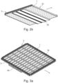
- FIG 2a shows schematically and exemplarily an embodiment of the substrate handling system S.
- the substrate handling system S comprises several immersion scanner units S2 arranged in series.
- the substrate holder S1 of the substrate handling system S comprises a substrate carrier 2 and a power contact unit 3.
- the substrate carrier 2 comprises a frame 2a to carry the substrate 1.
- the power contact unit 3 comprises a body 3a, a plurality of main legs 3b extending from the body 3a at least partially along an edge of the substrate carrier 2 and a plurality of side legs 3c each arranged essentially perpendicular at one of the main legs 3b to contact the substrate 1.
- the power contact unit 3 further comprises a plurality of retaining elements 3d provided between the body 3 a of the power contact unit 3 and the frame 2a of the substrate carrier 2 to retain a connection between the substrate 1 held by the frame 2a and the power contact unit 3.
- the substrate holder S1 for holding a substrate 1 further comprises several electric contact portions 5a arranged at the side legs 3c of the power contact units 3 to supply electric current to the substrate 1, also shown in Figures 4a, 5a and 6a .
- the main legs 3b, the side legs 3c, the electric contact portions 5a and/or the retaining elements 3d, in other words power contact units 3 as a whole are only arranged along two opposite edges of the substrate carrier 2.
- the substrate carrier 2 is
- Figure 2b shows schematically and exemplarily the embodiment of the substrate handling system S according to Figure 2a from another perspective. At least an anode may be present at a side of the immersion scanner unit S2. The anode here is integral with the immersion scanner unit S2.
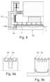
- Figure 3a shows schematically and exemplarily another embodiment of a substrate handling system S comprising a substrate holder S1 and an immersion scanner unit S2 according to the disclosure.
- the power contact units 3 (at least main legs 3b, the side legs 3c, the electric contact portions 5a and/or the retaining elements 3d) are arranged along all four edges of the substrate carrier 2.
- Figure 3b shows schematically and exemplarily the embodiment of the substrate handling system S according to Figure 3a from another perspective.
- Figure 4 shows schematically and exemplarily a cross-sectional view of an embodiment of a substrate handling system S comprising a substrate holder S1 and an immersion scanner unit S2 according to the disclosure.
- the retaining elements 3d comprise spring elements.
- the substrate carrier 2 is configured to carry only one substrate 1.
- Figure 4a shows schematically and exemplarily a cross-sectional detail view of the embodiment of the substrate holder S1 according to Figure 4 .
- the retaining element 3d in the form of a spring element is present between the body 3a and the frame 2a of the substrate carrier 2.
- a single substrate 1 is held in Figure 4a in contact with the electric contact portion 5a from one side and the frame 2a of the substrate carrier 2 from another side.
- FIGS 5, 5a , 6 and 6a show schematically and exemplarily a cross-sectional view of embodiments of the substrate holder S1 according to the disclosure.
- the power contact unit 3 is configured to contact the substrate 1 to supply electric current for surface treatment of the substrate 1.
- the power contact unit 3 comprises an electric contact portion 5a and a seal 5b around the electric contact portion 5a.
- the electric contact portion 5a contacts the substrate 1 as a single contact point.
- FIG 6a a detail of the substrate holder S1 of Figure 6 is shown.
- the substrate carrier 2a with the power contact unit 3 is at least partially inside a process fluid, which is depicted with the wavy line across the figure 6 .
- the power contact unit 3 comprises an electric contact portion 5a for transmitting electric current to the substrate 1 and a seal 5b around the electric contact portion 5a in the form of a bellow.
- the bellow form of the seal 5b causes, in addition to sealing, a vacuum effect on the contacted substrate 1, thereby securing a connection between the electric contact portion 5a and the substrate 1.
- Figures 7 and 8 show schematically and exemplarily detail views of embodiments of a substrate handling system S comprising at least a vacuum head 4 and electric contact portion 5a.
- the vacuum head 4 provides suction between the frame 2a of the substrate carrier 2 and the substrate 1. By aligning multiple vacuum heads 4 along for instance an edge of the frame 2a, a distributed suction force is applied to the substrate 1, preventing collection of stress points.
- the vacuum head 4 ensures a stable connection between the power contact unit 3 (more specifically electric contact portion 5a) and the substrate 1.
- the electric contact portions 5a in the Figures 7 and 8 are dry power contacts. Dry power contact is present between the power contact unit 3 and the substrate carrier 2 by providing a seal 5b around the electric contact portion 5a (not shown in Fig. 7 and 8 ).
- the substrate holder S1 further comprises an agitation unit (not shown in the figures) configured to move the substrate 1 relative to the immersion scanner unit S2 or the immersion scanner unit S2 relative to the substrate 1, preferably in up to three dimensions.
- an agitation unit (not shown in the figures) configured to move the substrate 1 relative to the immersion scanner unit S2 or the immersion scanner unit S2 relative to the substrate 1, preferably in up to three dimensions.
- FIG 9a and 9b show schematically and exemplarily detail views of embodiments of an electric contact portion 5a according to Figures 7 and 8 according to the disclosure.
- the electric contact portions 5a are dry power contacts surrounded with seals 5b.
Landscapes
- Chemical & Material Sciences (AREA)
- Engineering & Computer Science (AREA)
- Chemical Kinetics & Catalysis (AREA)
- Electrochemistry (AREA)
- Materials Engineering (AREA)
- Metallurgy (AREA)
- Organic Chemistry (AREA)
- Automation & Control Theory (AREA)
- Life Sciences & Earth Sciences (AREA)
- Sustainable Development (AREA)
- Container, Conveyance, Adherence, Positioning, Of Wafer (AREA)
Priority Applications (7)
| Application Number | Priority Date | Filing Date | Title |
|---|---|---|---|
| EP22154314.3A EP4219800A1 (en) | 2022-01-31 | 2022-01-31 | Substrate holder for holding a substrate in a chemical and/or electrolytic surface treatment of the substrate |
| KR1020247028971A KR20240144285A (ko) | 2022-01-31 | 2022-12-23 | 기판의 화학적 및/또는 전해 표면 처리에서 기판을 고정하는 기판 홀더 |
| US18/834,576 US20250137161A1 (en) | 2022-01-31 | 2022-12-23 | Substrate holder for holding a substrate in a chemical and/or electrolytic surface treatment of the substrate |
| JP2024545255A JP2025503298A (ja) | 2022-01-31 | 2022-12-23 | 基板の化学及び/又は電解表面処理において前記基板を保持する基板ホルダ |
| CN202280090561.8A CN118660992A (zh) | 2022-01-31 | 2022-12-23 | 用于在对基底进行化学和/或电解表面处理时固持基底的基底支架 |
| PCT/EP2022/087732 WO2023143842A1 (en) | 2022-01-31 | 2022-12-23 | Substrate holder for holding a substrate in a chemical and/or electrolytic surface treatment of the substrate |
| TW112103243A TW202334515A (zh) | 2022-01-31 | 2023-01-31 | 用於在基板之化學及/或電解表面處理中固定基板的基板支架 |
Applications Claiming Priority (1)
| Application Number | Priority Date | Filing Date | Title |
|---|---|---|---|
| EP22154314.3A EP4219800A1 (en) | 2022-01-31 | 2022-01-31 | Substrate holder for holding a substrate in a chemical and/or electrolytic surface treatment of the substrate |
Publications (1)
| Publication Number | Publication Date |
|---|---|
| EP4219800A1 true EP4219800A1 (en) | 2023-08-02 |
Family
ID=80218702
Family Applications (1)
| Application Number | Title | Priority Date | Filing Date |
|---|---|---|---|
| EP22154314.3A Pending EP4219800A1 (en) | 2022-01-31 | 2022-01-31 | Substrate holder for holding a substrate in a chemical and/or electrolytic surface treatment of the substrate |
Country Status (7)
| Country | Link |
|---|---|
| US (1) | US20250137161A1 (https=) |
| EP (1) | EP4219800A1 (https=) |
| JP (1) | JP2025503298A (https=) |
| KR (1) | KR20240144285A (https=) |
| CN (1) | CN118660992A (https=) |
| TW (1) | TW202334515A (https=) |
| WO (1) | WO2023143842A1 (https=) |
Citations (4)
| Publication number | Priority date | Publication date | Assignee | Title |
|---|---|---|---|---|
| US20060289302A1 (en) * | 2005-06-28 | 2006-12-28 | Semitool, Inc. | Electroprocessing workpiece contact assemblies, and apparatus with contact assemblies for electroprocessing workpieces |
| US20160222540A1 (en) * | 2012-03-27 | 2016-08-04 | Ebara Corporation | Plating method and plating apparatus |
| US10066311B2 (en) * | 2011-08-15 | 2018-09-04 | Lam Research Corporation | Multi-contact lipseals and associated electroplating methods |
| US10738390B2 (en) * | 2016-05-09 | 2020-08-11 | Ebara Corporation | Substrate holder and plating apparatus using the same |
-
2022
- 2022-01-31 EP EP22154314.3A patent/EP4219800A1/en active Pending
- 2022-12-23 KR KR1020247028971A patent/KR20240144285A/ko active Pending
- 2022-12-23 WO PCT/EP2022/087732 patent/WO2023143842A1/en not_active Ceased
- 2022-12-23 JP JP2024545255A patent/JP2025503298A/ja active Pending
- 2022-12-23 CN CN202280090561.8A patent/CN118660992A/zh active Pending
- 2022-12-23 US US18/834,576 patent/US20250137161A1/en active Pending
-
2023
- 2023-01-31 TW TW112103243A patent/TW202334515A/zh unknown
Patent Citations (4)
| Publication number | Priority date | Publication date | Assignee | Title |
|---|---|---|---|---|
| US20060289302A1 (en) * | 2005-06-28 | 2006-12-28 | Semitool, Inc. | Electroprocessing workpiece contact assemblies, and apparatus with contact assemblies for electroprocessing workpieces |
| US10066311B2 (en) * | 2011-08-15 | 2018-09-04 | Lam Research Corporation | Multi-contact lipseals and associated electroplating methods |
| US20160222540A1 (en) * | 2012-03-27 | 2016-08-04 | Ebara Corporation | Plating method and plating apparatus |
| US10738390B2 (en) * | 2016-05-09 | 2020-08-11 | Ebara Corporation | Substrate holder and plating apparatus using the same |
Also Published As
| Publication number | Publication date |
|---|---|
| US20250137161A1 (en) | 2025-05-01 |
| TW202334515A (zh) | 2023-09-01 |
| KR20240144285A (ko) | 2024-10-02 |
| CN118660992A (zh) | 2024-09-17 |
| WO2023143842A1 (en) | 2023-08-03 |
| JP2025503298A (ja) | 2025-01-30 |
Similar Documents
| Publication | Publication Date | Title |
|---|---|---|
| US8172989B2 (en) | Prevention of substrate edge plating in a fountain plating process | |
| US5985123A (en) | Continuous vertical plating system and method of plating | |
| TWI649460B (zh) | 濕式處理系統及其操作方法 | |
| US10351968B2 (en) | Front referenced anode | |
| TWI248992B (en) | Substrate holder system with substrate extension apparatus and associated method | |
| JP6222145B2 (ja) | 金属皮膜の成膜装置およびその成膜方法 | |
| KR102272508B1 (ko) | 이방성 고 저항 이온성 전류 소스 | |
| WO1999054920A3 (en) | Electro-chemical deposition cell for face-up processing of single semiconductor substrates | |
| KR20190020135A (ko) | 습식 처리 시스템을 위한 워크피스 홀더 | |
| US11608563B2 (en) | Electrochemical deposition systems | |
| KR20150043522A (ko) | 제품 홀딩 기기 및 처리 방법 | |
| US20080035474A1 (en) | Apparatus for electroprocessing a substrate with edge profile control | |
| US7067045B2 (en) | Method and apparatus for sealing electrical contacts during an electrochemical deposition process | |
| EP4219800A1 (en) | Substrate holder for holding a substrate in a chemical and/or electrolytic surface treatment of the substrate | |
| CN104641023B (zh) | 利用内部阳极对处理物品电镀覆层 | |
| US11105014B2 (en) | Distribution system for chemical and/or electrolytic surface treatment | |
| WO2003010368A1 (en) | Method and apparatus for sealing a substrate surface during an electrochemical deposition process | |
| JP3154267U (ja) | めっき処理物保持具 | |
| JP7425483B2 (ja) | ワークの半導体層の一面をエッチングするための装置及び方法 | |
| KR102914503B1 (ko) | 기판의 화학적 및/또는 전해 표면 처리 중 기판을 홀딩하기 위한 도금 프레임 유닛 | |
| CN111032928B (zh) | 用于印刷线路板的镀敷设备和金属夹具 | |
| US20050258044A1 (en) | Magnetic focus rings for improved copper plating | |
| JP2022554027A (ja) | 化学および/または電解表面処理のための基板保持およびロックシステム | |
| WO2024115192A1 (en) | Distribution system for the simultaneous chemical and/or electrolytic surface treatment of at least two substrates | |
| KR20190051387A (ko) | 전력 공급용 지그 |
Legal Events
| Date | Code | Title | Description |
|---|---|---|---|
| PUAI | Public reference made under article 153(3) epc to a published international application that has entered the european phase |
Free format text: ORIGINAL CODE: 0009012 |
|
| STAA | Information on the status of an ep patent application or granted ep patent |
Free format text: STATUS: REQUEST FOR EXAMINATION WAS MADE |
|
| 17P | Request for examination filed |
Effective date: 20221221 |
|
| AK | Designated contracting states |
Kind code of ref document: A1 Designated state(s): AL AT BE BG CH CY CZ DE DK EE ES FI FR GB GR HR HU IE IS IT LI LT LU LV MC MK MT NL NO PL PT RO RS SE SI SK SM TR |
|
| STAA | Information on the status of an ep patent application or granted ep patent |
Free format text: STATUS: EXAMINATION IS IN PROGRESS |
|
| P01 | Opt-out of the competence of the unified patent court (upc) registered |
Effective date: 20231021 |
|
| 17Q | First examination report despatched |
Effective date: 20231121 |