EP4209674A1 - Geteilte schaufel, fluidantriebsvorrichtung und proportionalmischer für fluidantrieb - Google Patents
Geteilte schaufel, fluidantriebsvorrichtung und proportionalmischer für fluidantrieb Download PDFInfo
- Publication number
- EP4209674A1 EP4209674A1 EP21868322.5A EP21868322A EP4209674A1 EP 4209674 A1 EP4209674 A1 EP 4209674A1 EP 21868322 A EP21868322 A EP 21868322A EP 4209674 A1 EP4209674 A1 EP 4209674A1
- Authority
- EP
- European Patent Office
- Prior art keywords
- split
- rotor
- type blade
- valve plates
- fluid
- Prior art date
- Legal status (The legal status is an assumption and is not a legal conclusion. Google has not performed a legal analysis and makes no representation as to the accuracy of the status listed.)
- Granted
Links
Images






Classifications
-
- F—MECHANICAL ENGINEERING; LIGHTING; HEATING; WEAPONS; BLASTING
- F01—MACHINES OR ENGINES IN GENERAL; ENGINE PLANTS IN GENERAL; STEAM ENGINES
- F01C—ROTARY-PISTON OR OSCILLATING-PISTON MACHINES OR ENGINES
- F01C1/00—Rotary-piston machines or engines
- F01C1/30—Rotary-piston machines or engines having the characteristics covered by two or more groups F01C1/02, F01C1/08, F01C1/22, F01C1/24 or having the characteristics covered by one of these groups together with some other type of movement between co-operating members
- F01C1/34—Rotary-piston machines or engines having the characteristics covered by two or more groups F01C1/02, F01C1/08, F01C1/22, F01C1/24 or having the characteristics covered by one of these groups together with some other type of movement between co-operating members having the movement defined in group F01C1/08 or F01C1/22 and relative reciprocation between the co-operating members
- F01C1/344—Rotary-piston machines or engines having the characteristics covered by two or more groups F01C1/02, F01C1/08, F01C1/22, F01C1/24 or having the characteristics covered by one of these groups together with some other type of movement between co-operating members having the movement defined in group F01C1/08 or F01C1/22 and relative reciprocation between the co-operating members with vanes reciprocating with respect to the inner member
- F01C1/3441—Rotary-piston machines or engines having the characteristics covered by two or more groups F01C1/02, F01C1/08, F01C1/22, F01C1/24 or having the characteristics covered by one of these groups together with some other type of movement between co-operating members having the movement defined in group F01C1/08 or F01C1/22 and relative reciprocation between the co-operating members with vanes reciprocating with respect to the inner member the inner and outer member being in contact along one line or continuous surface substantially parallel to the axis of rotation
- F01C1/3442—Rotary-piston machines or engines having the characteristics covered by two or more groups F01C1/02, F01C1/08, F01C1/22, F01C1/24 or having the characteristics covered by one of these groups together with some other type of movement between co-operating members having the movement defined in group F01C1/08 or F01C1/22 and relative reciprocation between the co-operating members with vanes reciprocating with respect to the inner member the inner and outer member being in contact along one line or continuous surface substantially parallel to the axis of rotation the surfaces of the inner and outer member, forming the working space, being surfaces of revolution
-
- B—PERFORMING OPERATIONS; TRANSPORTING
- B01—PHYSICAL OR CHEMICAL PROCESSES OR APPARATUS IN GENERAL
- B01F—MIXING, e.g. DISSOLVING, EMULSIFYING OR DISPERSING
- B01F35/00—Accessories for mixers; Auxiliary operations or auxiliary devices; Parts or details of general application
- B01F35/30—Driving arrangements; Transmissions; Couplings; Brakes
- B01F35/32—Driving arrangements
- B01F35/32005—Type of drive
- B01F35/32015—Flow driven
-
- F—MECHANICAL ENGINEERING; LIGHTING; HEATING; WEAPONS; BLASTING
- F03—MACHINES OR ENGINES FOR LIQUIDS; WIND, SPRING, OR WEIGHT MOTORS; PRODUCING MECHANICAL POWER OR A REACTIVE PROPULSIVE THRUST, NOT OTHERWISE PROVIDED FOR
- F03C—POSITIVE-DISPLACEMENT ENGINES DRIVEN BY LIQUIDS
- F03C2/00—Rotary-piston engines
- F03C2/30—Rotary-piston engines having the characteristics covered by two or more of groups F03C2/02, F03C2/08, F03C2/22, F03C2/24 or having the characteristics covered by one of these groups together with some other type of movement between co-operating members
- F03C2/304—Rotary-piston engines having the characteristics covered by two or more of groups F03C2/02, F03C2/08, F03C2/22, F03C2/24 or having the characteristics covered by one of these groups together with some other type of movement between co-operating members having both the movements defined in sub-group F03C2/08 or F03C2/22 and relative reciprocation between members
-
- B—PERFORMING OPERATIONS; TRANSPORTING
- B01—PHYSICAL OR CHEMICAL PROCESSES OR APPARATUS IN GENERAL
- B01F—MIXING, e.g. DISSOLVING, EMULSIFYING OR DISPERSING
- B01F35/00—Accessories for mixers; Auxiliary operations or auxiliary devices; Parts or details of general application
- B01F35/30—Driving arrangements; Transmissions; Couplings; Brakes
- B01F35/31—Couplings
-
- B—PERFORMING OPERATIONS; TRANSPORTING
- B01—PHYSICAL OR CHEMICAL PROCESSES OR APPARATUS IN GENERAL
- B01F—MIXING, e.g. DISSOLVING, EMULSIFYING OR DISPERSING
- B01F35/00—Accessories for mixers; Auxiliary operations or auxiliary devices; Parts or details of general application
- B01F35/80—Forming a predetermined ratio of the substances to be mixed
- B01F35/83—Forming a predetermined ratio of the substances to be mixed by controlling the ratio of two or more flows, e.g. using flow sensing or flow controlling devices
- B01F35/831—Forming a predetermined ratio of the substances to be mixed by controlling the ratio of two or more flows, e.g. using flow sensing or flow controlling devices using one or more pump or other dispensing mechanisms for feeding the flows in predetermined proportion, e.g. one of the pumps being driven by one of the flows
-
- F—MECHANICAL ENGINEERING; LIGHTING; HEATING; WEAPONS; BLASTING
- F01—MACHINES OR ENGINES IN GENERAL; ENGINE PLANTS IN GENERAL; STEAM ENGINES
- F01C—ROTARY-PISTON OR OSCILLATING-PISTON MACHINES OR ENGINES
- F01C21/00—Component parts, details or accessories not provided for in groups F01C1/00 - F01C20/00
- F01C21/08—Rotary pistons
-
- F—MECHANICAL ENGINEERING; LIGHTING; HEATING; WEAPONS; BLASTING
- F01—MACHINES OR ENGINES IN GENERAL; ENGINE PLANTS IN GENERAL; STEAM ENGINES
- F01C—ROTARY-PISTON OR OSCILLATING-PISTON MACHINES OR ENGINES
- F01C21/00—Component parts, details or accessories not provided for in groups F01C1/00 - F01C20/00
- F01C21/08—Rotary pistons
- F01C21/0809—Construction of vanes or vane holders
- F01C21/0881—Construction of vanes or vane holders the vanes consisting of two or more parts
-
- F—MECHANICAL ENGINEERING; LIGHTING; HEATING; WEAPONS; BLASTING
- F03—MACHINES OR ENGINES FOR LIQUIDS; WIND, SPRING, OR WEIGHT MOTORS; PRODUCING MECHANICAL POWER OR A REACTIVE PROPULSIVE THRUST, NOT OTHERWISE PROVIDED FOR
- F03B—MACHINES OR ENGINES FOR LIQUIDS
- F03B3/00—Machines or engines of reaction type; Parts or details peculiar thereto
- F03B3/10—Machines or engines of reaction type; Parts or details peculiar thereto characterised by having means for functioning alternatively as pumps or turbines
-
- F—MECHANICAL ENGINEERING; LIGHTING; HEATING; WEAPONS; BLASTING
- F03—MACHINES OR ENGINES FOR LIQUIDS; WIND, SPRING, OR WEIGHT MOTORS; PRODUCING MECHANICAL POWER OR A REACTIVE PROPULSIVE THRUST, NOT OTHERWISE PROVIDED FOR
- F03B—MACHINES OR ENGINES FOR LIQUIDS
- F03B3/00—Machines or engines of reaction type; Parts or details peculiar thereto
- F03B3/12—Blades; Blade-carrying rotors
- F03B3/121—Blades, their form or construction
-
- F—MECHANICAL ENGINEERING; LIGHTING; HEATING; WEAPONS; BLASTING
- F03—MACHINES OR ENGINES FOR LIQUIDS; WIND, SPRING, OR WEIGHT MOTORS; PRODUCING MECHANICAL POWER OR A REACTIVE PROPULSIVE THRUST, NOT OTHERWISE PROVIDED FOR
- F03C—POSITIVE-DISPLACEMENT ENGINES DRIVEN BY LIQUIDS
- F03C2/00—Rotary-piston engines
- F03C2/30—Rotary-piston engines having the characteristics covered by two or more of groups F03C2/02, F03C2/08, F03C2/22, F03C2/24 or having the characteristics covered by one of these groups together with some other type of movement between co-operating members
- F03C2/302—Rotary-piston engines having the characteristics covered by two or more of groups F03C2/02, F03C2/08, F03C2/22, F03C2/24 or having the characteristics covered by one of these groups together with some other type of movement between co-operating members having both the movements defined in sub-groups F03C2/02 and relative reciprocation between members
-
- F—MECHANICAL ENGINEERING; LIGHTING; HEATING; WEAPONS; BLASTING
- F04—POSITIVE - DISPLACEMENT MACHINES FOR LIQUIDS; PUMPS FOR LIQUIDS OR ELASTIC FLUIDS
- F04B—POSITIVE-DISPLACEMENT MACHINES FOR LIQUIDS; PUMPS
- F04B9/00—Piston machines or pumps characterised by the driving or driven means to or from their working members
- F04B9/08—Piston machines or pumps characterised by the driving or driven means to or from their working members the means being fluid
- F04B9/10—Piston machines or pumps characterised by the driving or driven means to or from their working members the means being fluid the fluid being liquid
-
- Y—GENERAL TAGGING OF NEW TECHNOLOGICAL DEVELOPMENTS; GENERAL TAGGING OF CROSS-SECTIONAL TECHNOLOGIES SPANNING OVER SEVERAL SECTIONS OF THE IPC; TECHNICAL SUBJECTS COVERED BY FORMER USPC CROSS-REFERENCE ART COLLECTIONS [XRACs] AND DIGESTS
- Y02—TECHNOLOGIES OR APPLICATIONS FOR MITIGATION OR ADAPTATION AGAINST CLIMATE CHANGE
- Y02E—REDUCTION OF GREENHOUSE GAS [GHG] EMISSIONS, RELATED TO ENERGY GENERATION, TRANSMISSION OR DISTRIBUTION
- Y02E10/00—Energy generation through renewable energy sources
- Y02E10/20—Hydro energy
Definitions
- the present application relates to a field of fluid driving technology and in particular, relates to a split-type blade, a fluid driving device and a fluid driving proportional mixer.
- the fluid driving device such as a hydraulic motor, serving as an energy conversion device to converse the pressure energy of the fluid into the mechanical energy
- the hydraulic motor on the current market generally includes a housing, a stator and a rotor, in which the stator is fixedly connected in the housing, and the blade slidable in the radial direction is provided in the rotor.
- the rotor is eccentrically arranged in the chamber of the stator.
- the current hydraulic motor generally adopts the traditional blade, in which one end of the traditional blade can be slidably inserted in the rotor along the radial direction, so that the other end of the traditional blade is slid to abut against the wall of the inner chamber of the stator under the effect of the centrifugal force.
- the traditional blade is generally adapted to the hydraulic motor with a higher rotation speed. Due to the low rotation speed, the centrifugal force is too small to cause the sliding of the traditional blade, resulting in a relatively large gap between the traditional blade and the stator, so as to lead to a serious leakage that influences the normal operation of the hydraulic motor.
- some of the hydraulic motors are additionally equipped with a spring structure, so that the traditional blade can abut against the inner wall of the rotor by using the elastic force in a low rotation speed.
- the spring structure has a large stroke, so as to result in a relatively large spring compression force. Therefore, the applied force between the traditional blade and the stator is relatively large, causing a serious abrasion between the traditional blade and the stator and a large noise, which may greatly reduce the service life of the hydraulic motor.
- some of the hydraulic motors directly remove the traditional blade and adopt the integrated penetrating blade with an integral structure.
- the integrated penetrating blade is penetrating provided in the rotor, and the integrated penetrating blade can slide along the radial direction of the rotor, so that two end portions of the integrated penetrating blade abut against the inner wall of the stator throughout in any rotation speed, and the integrated penetrating blade is slid on the inner wall of the stator.
- the integrated penetrating blade is an integration, which is difficult to have a high flatness.
- the integrated penetrating blade can slidably penetrate the rotor, so that there is a relatively large gap between the integrated penetrating blade and the rotor, causing a serious abrasion between the contacting surfaces thereof, which will lead to a serious leakage problem.
- One of the purposes in the present application is to provide a split-type blade, a fluid driving device and a fluid driving proportional mixer, to reduce the gap between the blade and the rotor, facilitating reducing the fluid leakage of the fluid driving device.
- the split-type driving device adopts a structure of penetrated pushing rod, so as to ensure a low rotation speed of the fluid driving device and a reduced contacting surface and gap between the blade and the rotor, facilitating reducing abrasion and leakage.
- Another purpose in the present application is to provide a split-type blade, a fluid driving device and a fluid driving proportional mixer.
- the split-type blade has a relatively high flatness, facilitating reducing the abrasion and noise caused in the operation of the fluid driving device.
- Another purpose in the present application is to provide a split-type blade, a fluid driving device and a fluid driving proportional mixer.
- the pushing rod of the split-type blade can be made of metal material, so as to have a high precision, facilitating further reducing the gap between the split-type blade and the rotor and minimizing the leakage.
- valve plate of the split-type blade can be made of plastic, facilitating reducing the whole weight of the split-type blade, reducing the abrasion of the split-type blade and the stator, and reducing the noise in the operation.
- Another purpose in the present application is to provide a split-type blade, a fluid driving device and a fluid driving proportional mixer.
- a reinforced rib is provided on the valve plate of the split-type blade, facilitating improving the strength of the valve plate, so as to prevent the valve plate from being deformed and damaged.
- Another purpose in the present application is to provide a split-type blade, a fluid driving device and a fluid driving proportional mixer.
- the reinforced rib of the split-type blade is disposed at a connection portion between the valve plate and the pushing rod, facilitating improving the connection strength and connection stability between the valve plate and the pushing rod.
- valve plate of the split-type blade has an arc structure with hyperbolic radius, facilitating reducing the leakage and abrasion between the valve plate and the stator.
- Another purpose in the present application is to provide a split-type blade, a fluid driving device and a fluid driving proportional mixer.
- the fluid driving device can balance the pressure differential in the radial direction of the valve plate of the split-type blade by using ta balance hole provided in the rotor, facilitating reducing the abrasion between the split-type blade and the rotor.
- Another purpose in the present application is to provide a split-type blade, a fluid driving device and a fluid driving proportional mixer.
- the present application is not required to adopt expensive materials or complex structure. Therefore, the present application successfully and effectively provides a technical solution, not only providing the simple split-type blade, fluid driving device and fluid driving proportional mixer, but also increasing the utility and reliability of the split-type blade, fluid driving device and fluid driving proportional mixer.
- the present application provides a split-type blade serving as the accessory of the fluid driving device for converting the pressure energy of the fluid into the mechanical energy, in order to realize at least one of the above purposes or other purposes and advantages.
- the split-type blade includes:
- the pushing rod and the valve plate are made of different materials, and a material strength of the pushing rod is larger than a material strength of the valve plate.
- the pushing rod is made of metal material
- the valve plate is made of nonmetal material
- the plurality of the pushing rods are equally disposed at an interval, and two end portions of each pushing rod are respectively connected to inner edge portions of two valve plates.
- one or more matching grooves are provided in the inner edge portion of the valve plate, in which the end portion of the pushing rod is inserted in the matching groove of the valve plate, to rigidly or flexibly connect the pushing rod to the valve plate.
- the split-type blade further includes one or more reinforcing elements, in which the reinforcing element is correspondingly disposed on the valve plate at a connection portion with the pushing rod to reinforce the connection strength between the valve plate and the pushing rod.
- the reinforcing element adopts two reinforced ribs that are symmetrically disposed at the front and rear sides of the matching groove of the valve plate, and each of the two reinforced ribs is extended from the inner edge portion of the valve plate to the outer edge portion of the valve plate.
- the reinforcing element adopts a reinforced rib that is correspondingly disposed at the front and rear sides of the matching groove of the valve plate, and the reinforced rib is extended from the inner edge portion of the valve plate to the outer edge portion of the valve plate.
- the matching groove of the valve plate is backwards and eccentrically disposed at the inner edge portion of the valve plate, so that the matching groove is positioned at a connection portion between the inner edge portion of the valve plate and the reinforced rib.
- a section area of a middle portion of the pushing rod is larger than a section area of the end portion of the pushing rod, and two end portions of the pushing rod are integrated and respectively extended outwards from two ends of the middle portion of the pushing rod along a direction parallel to a center axis of the middle portion.
- the outer edge portion of the valve plate has an arc end surface, and the arc end surface has a hyperbolic radius arc structure or single radius arc structure.
- an arc portion with a larger curvature radius of the arc end surface with the hyperbolic radius arc structure has a same curvature radius with a envelope curve of the inner wall of the stator in a negative displacement area.
- the split-type blade further includes at least two elastic members, in which each of the two elastic members is correspondingly disposed on a middle end surface of the outer edge portion of the valve plate, so that the elastic member is positioned between the valve plate and the stator when the valve plate is positioned in the positive displacement area or the negative displacement area of the stator, playing a sealing role.
- the pushing rod is flexibly connected to the valve plate by a fastening member or a miniature spring; or the pushing rod is rigidly connected to the valve plate through an interference fit.
- the present application further provides a fluid driving device, for partly converting the pressure energy of the fluid into the mechanical energy.
- the fluid driving device includes:
- At least two penetrating through holes are provided in the rotor, in which each of the at least two penetrating through holes is extended along the radial direction of the rotor to penetrate the rotor for being slidably mounted in the split-type blade.
- each penetrating through hole of the rotor includes one or more sliding holes and two retracting grooves, in which two retracting grooves are symmetrically provided on a periphery of the rotor, the sliding hole is extended from one retracting groove to another retracting groove; the pushing rod of the split-type blade is slidably mounted in the sliding hole of the rotor, and the valve plate is retractable mounted in the retracting groove of the rotor.
- At least two pairs of sealing grooves are further provided in the rotor, two sealing grooves in each pair of the sealing grooves are respectively disposed on sidewalls of two retracting grooves of the penetrating through hole of the rotor, the sealing grooves are configured to accommodate the sealing member to seal a gap between the valve plate and the rotor by the sealing member.
- the split-type blade further includes one or more reinforcing elements, in which the reinforcing element is correspondingly disposed on the valve plate at a connection portion with the pushing rod to reinforce the connection strength between the valve plate and the pushing rod, the rotor further includes an eccentric groove backwards extending from the retracting groove or a concentric groove frontwards extending from the retracting groove, for slidably accommodating the reinforcing elements.
- a plurality of balance holes are provided in the rotor, each of the plurality of balance holes is positioned in the rotor and is communicated with a bottom of the corresponding retracting groove; when the valve plate of the split-type blade slides to an inlet area and an outlet area of the stator, the balance hole corresponding to the valve plate is configured to introduce fluid in the retracting groove to balance the pressure differential of the valve plate along the radial direction.
- the present application further provides a fluid driving proportional mixer for mixing a first fluid and a second fluid.
- the fluid driving proportional mixer includes:
- the term "a” in the claims and specification should be understood as “one or more”, that is, the number of the element can be one in an embodiment, and can be more than one in other embodiments. Unless the disclosure of the present application clearly indicates that the number of the element is only one, the term “a” cannot be understood as unique or single, and the term “a” cannot be understood as a limitation on the number.
- connection can be a fixed connection, a detachable connection or integrated connection; the connection can be a mechanical connection or an electrical connection; and the connection can be a direct connection or an indirect connection via medium.
- connection can be a fixed connection, a detachable connection or integrated connection; the connection can be a mechanical connection or an electrical connection; and the connection can be a direct connection or an indirect connection via medium.
- the reference terms “an embodiment”, “some embodiments”, “example”, “specific example” or “some examples” mean that the specific feature, structure, material or characteristic illustrated in this embodiment or example is included in at least one embodiments or examples of the present application.
- the exemplary expression of the above terms does not have to refer to the same embodiment or example.
- the specific features, structures, materials or characteristics can be combined in a suitable manner in any one or more embodiments or examples. Without contradiction, those skilled in the art can combine different embodiments or examples described in this specification with the features in different embodiments or examples.
- the blade of the current hydraulic motor is either a traditional blade that is radially retractable on the rotor, or an integrated penetrating blade that is radially slidable on the rotor.
- the traditional blade has a problem that it cannot be operated in a low rotation speed.
- the integrated penetrating blade results in a large leakage and abrasion between the blade and the rotor due to the low flatness and deformable capacity. Therefore, the present application provides a split-type blade, to solve the problem that the traditional blade cannot be operated in a low rotation speed, and solve the problem of serious leakage and abrasion between the integrated penetrating blade and the rotor.
- the split-type blade 10 serves as an accessory of a fluid driving device 1 and is mounted in a rotor 20 of the fluid driving device 1, so as to converse the pressure energy of the fluid into the mechanical energy.
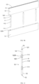
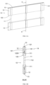
- the split-type blade 10 includes a pushing rod 11 and two valve plates 12.
- the pushing rod 11 is configured to be slidably disposed in the rotor 20 of the fluid driving device 1 along a radial direction.
- Two valve plates 12 are respectively mounted on two end portions of the pushing rod 11 in parallel. Each of two valve plates 12 is extended outwards along the pushing rod 11 to form the split-type blade 10 with a penetrating pushing rod structure.
- the pushing rod 11 of the split-type blade 10 slides along a radial direction of the rotor 20 to ensure an outer edge portion of each valve plate 12 abuts against an inner wall 31 of a stator 30 of the fluid driving device 1 throughout.
- the fluid adopted in the fluid driving device 1 can be but not limited to liquid water such as extinguishing water, river water or sea water. It can also be implemented as other types of fluids such as solution, air, and so on.
- each valve plate 12 of the split-type blade 10 in the present application has a greatly smaller dimension than the integrated penetrating blade.
- the valve plate 12 has a high flatness even adopts the same sheet material of the integrated penetrating blade, which can reduce the risk of deformation of valve plate 12, facilitating reducing the abrasion between the valve plate 12 of the split-type blade 10 and the rotor 20, so as to improve the service life of the split-type blade 10.
- the pushing rod 11 and the valve plate 12 of the split-type blade 10 are made of different materials.
- the material strength of the pushing rod 11 is larger than a material strength of the valve plate 12, so that the whole structure of the split-type blade 10 has a sufficient strength.
- the section area of the pushing rod 11 is greatly smaller than the section area of the valve plate 12, greatly reducing the contacting area between the pushing rod 11 and the rotor 20, further to reduce the abrasion between the pushing rod 11 of the split-type blade 10 and the rotor 20, and improve the service life of the split-type blade 10.
- the existing integrated penetrating blade is generally made of the plastic sheet material.
- the section area of the connection portion of the integrated penetrating blade cannot be too small, instead, the section area should be as large as possible to ensure a sufficient strength of the integrated penetrating blade, resulting in a larger contacting area between the integrated penetrating blade and the rotor. Which may not only increase the abrasion, but also lead to a serious leakage.
- the pushing rod 11 of the split-type blade 10 can be made of metal material such as stainless steel, carbon steel or alloy, facilitating the surface precision of the pushing rod 11, which greatly reduces the gap between the pushing rod 11 and the rotor 20, further to reduce the leakage between the split-type blade 10 and the rotor 20.
- the rotor 20 is generally made of metal material such as stainless steel. The matching degree between the rotor 20 and the pushing rod 11 can be improved by improving the machining accuracy, so as to greatly reduce the gap therebetween and further to reduce the leakage.
- valve plate 12 of the split-type blade 10 can be made of plastic or resin material such as PVDF (Polyvinylidene Difluoride) or PVC (Polyvinyl Chloride), so as to reduce the abrasion and noise when the valve plate 12 slides on the inner wall 31 of the stator 30.
- PVDF Polyvinylidene Difluoride
- PVC Polyvinyl Chloride
- the split-type blade 10 includes three pushing rods 11 and two valve plates 12. Three pushing rods 11 are equally disposed at an interval. Two end portions 111 of each pushing rod 11 are respectively connected to the inner edge portions 122 of two valve plates 12, to form the split-type blade 10 with split-type pushing rod structure. Two valve plates 12 are supportably connected to each other by three pushing rods 11, so that the whole structure of the split-type blade 10 has a sufficient strength, preventing the split-type blade 10 from deforming, which facilitates improving the quality and the service life of the split-type blade 10.
- the split-type blade 10 in FIG.s 1-8 and the following description takes three pushing rods 11 as an example to explain the characteristics and advantages of the split-type blade 10.
- the split-type blade 10 can includes one, two or more than three pushing rods 11 according to the different demand.
- valve plate 12 of the split-type blade 10 can be detachably mounted in the end portion 111 of the pushing rod 11 to facilitate maintaining and replacing the split-type blade 10.
- a matching groove 1220 is provided in the inner edge portion 122 of the valve plate 12 of the split-type blade 10.
- the end portion 111 of the pushing rod 11 can be inserted in the matching groove 1220 of the inner edge portion 122 of the valve plate 12, so as to realize the connection between the valve plate 12 and the pushing rod 11.
- the pushing rod 11 of the split-type blade 10 is flexibly connected to the valve plate 12.
- the pushing rod 11 is connected to the valve plate 12 via a fastening member 151 (such as screw).
- a screw-matching head is provided in the end portion 111 of the pushing rod 11 of the split-type blade 10, and a screw-matching groove is provided in the inner edge portion 122 of the valve plate 12 of the split-type blade 10.
- the screw-matching head of the end portion 111 of the pushing rod 11 is inserted in the screw-matching groove of the inner edge portion 122 of the valve plate 12.
- the valve plate 12 can be flexibly connected to the end portion 111 of the pushing rod 11 via a screw.
- the pushing rod 11 is flexibly connected to the valve plate 12 via a spring in another embodiment, specifically, the split-type blade 10 further includes one or more miniature springs.
- Each of the miniature springs is supported and connected between the pushing rod 11 and the valve plate 12, so as to realize a free retraction fine adjustment of the valve plate 12 by the miniature spring.
- the pushing rod 11 of the split-type blade 10 is rigidly connected to the valve plate 12, that is, the pushing rod 11 and the valve plate 12 are in a tight fit (interference fit).
- an interference-matching head is provided in the end portion 111 of the pushing rod 11 of the split-type blade 10
- an interference-matching groove is provided in the inner edge portion 122 of the valve plate 12 of the split-type blade 10.
- the interference-matching head of the end portion 111 of the pushing rod 11 is inserted in the interference-matching groove of the inner edge portion 122 of the valve plate 12, so that the valve plate 12 is rigidly connected to the end portion 111 of the pushing rod 11.
- the pushing rod 11 of the split-type blade 10 has a circular section area, so as to maximally reduce the external surface area with the sufficient strength of the pushing rod 11, which maximally reduce the contacting area between the pushing rod 11 and the rotor 20, further to reduce the abrasion and leakage between the pushing rod 11 and the rotor 20.
- the pushing rod 11 can also have a section area in a ellipse shape or a oblong shape, which won't be repeatedly described.
- the pushing rod 11 of the split-type blade 10 includes two end portions 111 and a middle portion 112 integrated with two end portion 111.
- the middle portion 112 has a same circular section with the end portion 111.
- the middle portion 112 of the pushing rod 11 is extended from one end portion 111 of the pushing rod 11 to another end portion 111 of the pushing rod 11 in a same cross section, so as to form the cylindrical pushing rod 11.
- the stator 30 of the fluid driving device 1 is divided into an inlet area 301, a positive displacement area 302, an outlet area 303 and a negative displacement area 304 along the rotation direction of the rotor 12 (anticlockwise direction in FIG.7 ).
- the envelope curves of the inner wall 31 of the stator 30 in the positive displacement area 302 and the negative displacement area 304 are configured as concentric arc curves.
- the envelope curve of the inner wall 31 of the stator 30 in the positive displacement area 302 has a larger curvature radius than the envelope curve in the negative displacement area 304.
- envelope curves of the inner wall 31 of the stator 30 are configured as a transmission curve, such as arc curve, Archimedean spiral line, Pascal spiral curve, logarithmic equation curve or other plane curves, so that an inner chamber 300 with a non-circular structure is formed in the stator 30.
- the outer edge portion 121 of the valve plate 12 of the split-type blade 10 has an arc end surface 1210.
- the arc end surface 1210 of the valve plate 12 has an arc structure with hyperbolic radius.
- the arc portion of the arc end surface 1210 of the valve plate 12 with a smaller radius abuts against the inner wall 31 of the stator 30, which facilitates reducing the abrasion between the valve plate 12 of the split-type blade 10 and the stator 30.
- the arc portion in the arc end surface 1210 of the valve plate 12 of the split-type blade 10 with a larger curvature radius has a same curvature with the envelope curve of the inner wall 31 of the stator 30 in the negative displacement area 304.
- the valve plate 12 of the split-type blade 10 is in a surface connection with the inner wall 31 of the stator 30 in the negative displacement area 304, so as to better guide the valve plate 12 of the split-type blade 10 to slide along the inner wall 31 of the stator 30, reduce the gap between the valve plate 12 of the split-type blade 10 and the inner wall 31 of the stator 30 in the negative displacement area 304, further to reduce the leakage.
- the arc end surface 1210 of the valve plate 12 of the split-type blade 10 includes a front end surface 1211, a rear end surface 1212 and a middle end surface 1213 positioned between the front end surface 1211 and the rear end surface 1212.
- the front end surface 1211 of the valve plate 12 faces the rotation direction of the rotor 20, and the rear end surface 1212 of the valve plate 12 is back to the rotation direction of the rotor 20.
- the front end surface 1211 has a same curvature radius with the rear end surface 1212, and has a smaller curvature radius than the middle end surface 1213.
- the middle end surface 1213 has a same curvature radius with the envelope curve of the inner wall 31 of the stator 30 in the negative displacement area 304. It should be understood that the rotation direction of the rotor 20 in the present application is configured to a direction from the rear end surface 1212 of the valve plate 12 to the front end surface 1211 of the valve plate 12.
- the contact position between the valve plate 12 of the split-type blade 10 and the rotor 20 are changed in different areas of the stator 30, which is conductive to reduce the abrasion of the split-type blade 10, improve the service life of the fluid driving device 1.
- the front end surface 1211 and the rear end surface 1212 of the valve plate 12 have relatively smaller curvature radius. Therefore, the gap between the valve plate 12 and the inner wall 31 of the stator 30 in the inlet area 301 and the outlet area 303 is relatively large, the contact area is relatively small, greatly reducing the abrasion between the split-type blade 10 and the stator 30.
- the middle end surface 1213 of the valve plate 12 has a relatively large curvature radius, the gap between the valve plate 12 and the inner wall 31 of the stator 30 in the positive displacement area 302 and the negative displacement area 304 is relatively small, and the contact area is relatively large, which is conductive to guide the split-type blade 10 to slide along the inner wall 31 of the stator 30, and to reduce the leakage of the fluid driving device 1.
- the arc end surface 1210 of the valve plate 12 of the split-type blade 10 has an arc structure with single curvature radius.
- the curvature radius of the arc end surface 1210 is preferred to be equal to the curvature radius of the envelope curve of the inner wall 31 of the stator 30 in the negative displacement area 304. That is, the front end surface 1211, the rear end surface 1212 and the middle end surface 1213 of the arc end surface 1210 of the valve plate 12 have the same curvature radius, which is equal to the curvature radius of the envelope curve of the inner wall 31 of the stator 30 in the negative displacement area 304.
- the envelop curves of the stator in the positive displacement area 302 and the negative displacement area 304 are arc curves.
- the split-type blade 10 doesn't have a swing angle when sliding in the positive displacement area 302 and the negative displacement area 304 of the stator 30, so that the contact position between the split-type blade 10 and the stator 30 in the positive displacement area 302 and the negative displacement area 304 is throughout in the middle end surface 1213 of the valve plate 12 of the split-type blade 10, resulting in a serious abrasion of the middle end surface 1213 of the outer edge portion 121 of the valve plate 12 of the split-type blade 10, causing a leakage of the fluid driving device 1 and a loss of the pressure energy of the fluid.
- the split-type blade 10 further includes at least two elastic members 13, as shown in FIG. 7 and FIG. 8 .
- Each of the elastic members 13 is correspondingly disposed in the middle end surface 1213 of the outer edge portion 121 of the valve plate 12, so that the elastic member 13 is positioned between the valve plate 12 and the inner wall 31 of the stator 30 when the valve plate 12 of the split-type blade 10 is in the positive displacement area 302 and the negative displacement area 304 of the stator, playing a sealing role.
- the elastic member 13 can seal the gap between the split-type blade 10 and the stator 30, preventing the fluid directly flowing from the inlet area 301 of the stator 30 to the outlet area 303 of the stator 30, effectively reducing the leakage and abrasion of the fluid driving device 1, and reducing the loss of the fluid pressure energy as possible.
- the elastic member 13 can be made of elastic material such as rubber, plastic, polymer material, metal materials and so on, but not limited thereto.
- the elastic member 13 can be implemented as the elastic member like elastic strip, O-ring, round gasket, arc strip, T-shaped strip, that can have a sealing effect to reduce the leakage, which won't be repeatedly described.
- the inner edge portion 122 of the valve plate 12 is provided with a matching groove 1220 at the connection position to the pushing rod 11, in order to mount the valve plate 12 on the end portion 111 of the pushing rod 11, which facilitates connecting to the end portion 111 of the pushing rod 11 in an inserting manner.
- the existence of the matching groove 1220 will weaken the strength of the connection portion between the inner edge portion 122 of the valve plate 12 and the pushing rod 11, resulting in a deformation or break of the valve plate 12 at this position, further influencing the property and service life of the split-type blade 10. Therefore, the present application can increase the strength of the connection position between the valve plate 12 and the pushing rod 11, so as to improve the whole strength of the split-type blade 10.
- the split-type blade 10 in this transformation solution differs from the above embodiments in that: the split-type blade 10 further includes one or more reinforcing element 14.
- the reinforcing element 14 is correspondingly disposed in the connection position between the valve plate 12 and the pushing rod 11, so as to reinforce the connection strength between the valve plate 12 and the pushing rod 11, increasing the whole strength of the split-type blade 10.
- the reinforcing element 14 is arranged on the external side of the matching groove 1220 of the valve plate 12, to increase the structural strength of the valve plate 12 at the matching groove 1220.
- the reinforcing element 14 of the split-type blade 10 is configured as two reinforced ribs 141.
- Two reinforced ribs 141 are symmetrically disposed on the front and rear sides of the matching groove 1220 of the valve plate 12.
- Each reinforced rib 141 is extended from the inner edge portion 122 of the valve plate 12 to the outer edge portion 121 of the valve plate 12, so as to reinforce the whole strength of the valve plate 12, preventing the valve plate 12 from deforming or breaking.
- the reinforced rib 141 is integrated and extended outwards from the valve plate 12 to increase the wall thickness of the matching groove 1220, so as to reinforce the strength of the valve plate 12 at the matching groove 1220.
- the reinforcing element 14 of the split-type blade 10 is configured as one reinforced rib 141.
- the reinforced rib 141 is correspondingly disposed on the front or rear side of the matching groove 1220 of the valve plate 12, having a reinforcing effect on the valve plate 12.
- the reinforced rib 141 is only provided on one side of the matching groove 1220 of the valve plate 12, the other side of the matching groove 1220 of the valve plate 12 cannot be reinforced, which is easy to break.
- the split-type blade 10 in this transformation solution differs from the second transformation solution in that: the reinforcing element 14 of the split-type blade 10 is configured as one reinforced rib 141 arranged at the rear side surface of the valve plate 12.
- the matching groove 1220 of the valve plate 12 is backwards and eccentrically disposed in the inner edge portion 122 of the valve plate 12, so that the matching groove 1220 is positioned at the connection position between the inner edge portion 122 of the valve plate 12 and the reinforced rib 131, increasing the wall thickness of the matching groove 1220, so as to realize the whole reinforcement effect on the valve plate 12 by one reinforced rib 141.
- each valve plate 12 is backwards shifted, so that the center point of the matching groove 1220 will deviate from the center axis of the split-type blade 10. Therefore, the end portion 111 of the pushing rod 11 of the split-type blade 10 backwards deviates from the center axis of the split-type blade 10, to align with the matching groove 1220, so that the centerlines of two end portions 111 of the pushing rod 11 are not in the same line.
- the middle portion 112 of the pushing rod 11 of the split-type blade 10 has a larger section area than the end portion 111 of the pushing rod 11.
- Two end portions 111 of the pushing rod 11 are respectively extended outwards from two opposite ends of the middle portion 112 along the centerline of the middle portion 112, so that two end portions 111 of the pushing rod 11 are respectively shifted towards the rear side surface of the corresponding valve plates 12.
- the middle portion 112 of the pushing rod 11 has the same section area with the end portion 111 of the pushing rod 11.
- the middle portion 112 of the pushing rod 11 is inclined or bent from one end portion 111 of the pushing rod 11 to the other end portion 111, which won't be repeatedly described.
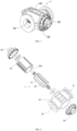
- the present application provides a fluid driving device 1, for converting the pressure energy of the fluid into the mechanical energy.
- the fluid driving device 1 includes at least one stator 30, at least one rotor 20 and at least two above split-type blades 10.
- Each rotor 20 is provided with an inner chamber 300m and each rotor 20 is rotatably arranged in the inner chamber 300 of the corresponding stator 30.
- Each split-type blade 10 is slidably mounted in the rotor along the radial direction.
- the split-type blade 10 includes one or more pushing rods 11 and two valve plates 12. Each pushing rod 11 is configured to slidably penetrate the rotor 20 along the radial direction.
- Each valve plate 12 is respectively mounted on two end portions 111 of each pushing rod 11 in parallel. Each valve plate 12 is extended outwards along the pushing rod, to form the split-type blade 10 with penetrating pushing rod.
- each pushing rod 11 of the split-type blade 10 slide along the radial direction of the rotor 20 to ensure an outer edge portion 121 of each valve plate 12 abuts against the inner wall 31 of the stator 30 throughout.
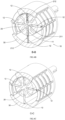
- the rotor 20 of the fluid driving device 1 is provided with at least two penetrating through holes 21.
- Each penetrating through hole 21 is extended along the radial direction of the rotor 20 to penetrate the rotor 20, for being slidably mounted in the split-type blade 10, so that the split-type blade 10 can slide in the penetrating through hole 21 in the radial direction, ensuring the sliding of the outer edge portion 121 of the valve plate 12 of the split-type blade 10 on the inner wall 31 of the stator 30.
- the at least two penetrating through holes 21 are preferred to be equally spaced in the rotor 20, so that the valve plates 12 of the split-type blade 10 mounted in the penetrating through holes 21 have a same distance therebetween, further to ensure the stable operation of the fluid driving device 1.
- each penetrating through hole 21 of the rotor 20 includes one or more sliding holes 211 and two retracting grooves 212.
- Two retracting grooves 212 are symmetrically provided on a periphery of the rotor 20.
- the sliding hole 211 is extended from one retracting groove 212 to another retracting groove 212, to communicate two retracting grooves 212, so as to form the penetrating through hole 21 penetrating the rotor 20.
- the pushing rod 11 of the split-type blade 10 is slidably mounted in the sliding hole 211 of the rotor 20, and the valve plate 12 of the split-type blade 10 is retractably mounted in the retracting groove 212 of the rotor 20, so that the split-type blade 10 can be slidably mounted in the penetrating through hole 21 of the rotor 20.
- the pushing rod 11 of the split-type blade 10 slides in the sliding hole 211 of the rotor 20 along the radial direction.
- the valve plate 12 of the split-type blade 10 is extended out or retracted in the retracting groove 212, so as to ensuring the sliding of the outer edge portion 121 of the valve plate 12 of the split-type blade 10 on the inner wall 31 of the stator 30.
- the rotor 20 of the fluid driving device 1 is further provided with two pairs of sealing grooves 22.
- Two sealing grooves 22 in each pair are respectively disposed on sidewalls (such as front sidewall) of two retracting grooves 212 of the corresponding penetrating through hole 21, which is configured to accommodation the sealing member (not shown in the figures).
- the sealing member seals the gap between the valve plate 12 of the split-type blade 10 and the rotor 20, to reduce the leakage of the fluid driving device 1.
- the rotor 20 of the fluid driving device 1 includes one or more bush (not shown in the figures).
- the bush is configured to be mounted in the sliding hole 211 of the penetrating through hole 21 of the rotor 20.
- the bush is arranged around the pushing rod 11 of the split-type blade 10, so as to greatly reduce the gap between the pushing rod 11 and the rotor 20, preventing the fluid from leaking from the gap between the pushing rod 11 of the split-type blade 10 and the rotor 20, minimizing the leakage of the fluid driving device 1.
- the split-type blade 10 slides in the radial direction only in the inlet area 301 and the outlet area 303, while doesn't slide in the radial direction in the positive displacement area 302 and the negative displacement area 304. Therefore, only the split-type blade 10 sliding in the inlet area 301 and the outlet area 303 of the stator 30 will abuts against the rotor 20 to cause the abrasion. In the inlet area 301 and the outlet area 303, the front and rear sides of the valve plate 12 of the split-type blade 10 have a large pressure differential, which may aggravate the abrasion between the split-type blade 10 and the rotor 20.
- the rotor 20 of the fluid driving device 1 is further provided with a plurality of the balance holes 23.
- Each balance hole 23 is positioned between the adjacent retracting grooves 212, and is communicated with the corresponding retracting groove 212.
- the balance hole 23 is configured to introduce fluid in the retracting groove 212 to balance the pressure differential of the valve plate 12 along the radial direction.
- the pressures on two sides of the split-type blade 10 are in a balance status in the inlet area 301 and the outlet area 303, so as to reduce the abrasion between the split-type blade 10 and the rotor 20.
- the rotor 20 of the fluid driving device 1 is provided with four balance holes 23.
- Each balance hole 23 is communicated with a bottom of the retracting groove 212 that positioned in front of the balance hole 23, so that the balance hole 23 introduces the fluid in the rear side of the valve plate 12 of the split-type blade 10 in the retracting groove 212, and fluid pressure is introduced from the front and rear sides of the valve plate 12 of the split-type blade 10, which facilitates balancing the pressure differential between the front and rear sides of the split-type blade 10, reducing the abrasion, and improving the service life of the split-type blade 10 and even the whole fluid driving device 1.
- the balance hole 23 can be communicated with the retracting groove 212 at other positions, as long as the communication position is positioned on the inner side of the sealing groove 22 of the retracting groove 212 (i.e., the connection position between the balance hole 23 and the retracting groove 212 is closer to the center axis of the rotor 20 than the sealing groove 22), so as to ensure pressure differential balance on front and rear sides of the valve plate 12 of the split-type blade 10 under the sealing effect of the sealing groove 22, which won't be repeatedly described.
- the fluid driving device 1 further includes a housing 40 and two end plates 50.
- the housing 40 is provided with an inlet tube 41 for introducing the fluid and an outlet tube 42 for discharging the fluid.
- the stator 30 is fixedly arranged in the housing 40.
- the rotor 20 is rotatably mounted in the housing 40 via the end plate 50.
- the inlet tube 41 of the housing 40 is corresponding to the inlet 32 of the stator 30 and the outlet tube 42 is corresponding to the outlet 33 of the stator, so that the fluid flows from the inlet tube 41 of the housing 40 in the inner chamber 300 of the stator through the inlet 32 of the stator 30, and further flows out of the outlet tube 42 of the housing 40 through the outlet 33 of the stator 30.
- the fluid drives the split-type blade to rotate, further drives the rotor 20 to rotate, so as to partly converse the pressure energy of the fluid into the mechanical energy.
- the rotor 20 can further drive the devices such as the plunger pump, and fan, to rotate, to realize the corresponding effect.
- the inlet 32 of the stator in the present application can be configured as grille openings.
- the grille openings are configured to be evenly distributed in the inlet area 301 of the stator 30, so that the fluid from the inlet 32 of the stator 30 can flow to two sides of the valve plate 12 of the split-type blade 10 in the inlet area 301 at the same time.
- the pressures of two sides of the split-type blade 10 are further balanced in the inlet area 301 of the stator 30, maximally reducing the abrasion between the split-type blade 10 and the rotor 20.
- the outlet 33 of the stator 30 in the present application can also be configured as the grille openings that are evenly distributed in the outlet area 303 of the stator 30.
- the split-type blade 10 is provided with a reinforced rib 141 at the rear side surface of the valve plate 12.
- the reinforced rib 141 of the split-type blade 10 adopts an eccentric structure design. Therefore, the split-type blade 10 can slide in the radial direction relative to the rotor 20.
- the penetrating through hole 21 of the rotor 20 of the fluid driving device 1 is matched with the structure of the split-type blade 10.
- the penetrating through hole 21 can be further includes an eccentric groove 213 corresponding to the reinforced rib 141.
- the eccentric groove 213 is extended backwards from the retracting groove 212, which is configured to slidably accommodate the reinforced rib 141, which is shown in FIG. 15 and FIG. 16 in detail, which won't be repeatedly described.
- the reinforced rib 141 of the split-type blade 10 adopts a concentric structure design.
- Two reinforced ribs 141 of each pair are symmetrically disposed on front and rear sides of the valve plate 12. Therefore, the penetrating through hole 21 can further include a concentric groove corresponding to each pair of the reinforced ribs 141.
- the concentric groove is extended frontwards and backwards from the retracting groove 212 at the same time, which is configured to slidably accommodate the reinforced rib 141.
- the present application provides a fluid driving proportional mixer for mixing a first fluid and a second fluid in a predetermined ratio.
- the fluid driving proportional mixer includes a fluid driving device 1, a pump device 2 and a coupling 3.
- the coupling 3 is configure to connect the fluid driving device 1 to the pump device 2.
- the first fluid such as extinguishing water
- the fluid driving device 1 is firstly partly converser the pressure energy of the first fluid into the mechanical energy, and outputs the first fluid.
- the coupling 3 transmits the mechanical energy conversed by the fluid driving device 1 to the pump device 2.
- the pump device 2 converses the mechanical energy transmitted by the coupling 3 into the pressure energy of the second fluid (such as foam liquid), and outputs the second fluid, so that the first fluid and the second fluid can mixed in the predetermined ratio.
- the predetermined ration mentioned in the present application can be but not limited to a ratio scope such as 1%, 3% or 6%.
- the predetermined ratio can be within the range of 3%-9%.
- the pump device 2 can be configured as but not limited to a reciprocating piston pump.
- the reciprocating piston pump can be reciprocated in the fluid driving device 1 driven by the coupling 3, so as to suck the second fluid and introduce the second fluid in the first fluid, so as to realize the mixture of the first fluid and the second fluid.
- the pump device 2 can also be configured as other types of pumps such as centrifugal pump, axial flow pump, partial flow pump or vortex pump.
- the fluid driving proportional mixer further includes a piping device 4.
- the piping device 4 includes a mixing pipe and a cleaning pipe.
- the mixing pipe communicates the outlet of the reciprocating piston pump with the outlet of the fluid driving device 1, which is configured to transmit the second fluid transmitted by the reciprocating piston pump to the outlet of the fluid driving device 1 through the mixing pipe.
- the second fluid transmitted by the reciprocating piston pump can be mixed with the first fluid transmitted by the fluid driving device 1 in a ratio.
- the cleaning pipe communicates the inlet of the reciprocating piston pump with the inlet of the fluid driving device 1, which is configured to transmit the first fluid from the inlet of the fluid driving device 1 to the inlet of the reciprocating piston pump, so that the reciprocating piston pump and the mixing pipe can be cleaned by the first fluid before or after the mixing.
- the mixing pipe and/or the cleaning pipe can be provided with various pipe auxiliary elements that meet the cleaning requirements such as manual ball valve, check valve, exhaust valve, pressure gauge, or instrument valve, which are not limited thereto. It won't be repeatedly described in the present application.
- the fluid driving proportional mixer in the present application enjoys the following advantages:
Landscapes
- Engineering & Computer Science (AREA)
- Mechanical Engineering (AREA)
- General Engineering & Computer Science (AREA)
- Chemical & Material Sciences (AREA)
- Combustion & Propulsion (AREA)
- Chemical Kinetics & Catalysis (AREA)
- Rotary Pumps (AREA)
- Multiple-Way Valves (AREA)
Applications Claiming Priority (2)
| Application Number | Priority Date | Filing Date | Title |
|---|---|---|---|
| CN202010984748.5A CN113719403B (zh) | 2020-09-18 | 2020-09-18 | 分体式叶片、流体驱动装置以及流体驱动比例混合器 |
| PCT/CN2021/110814 WO2022057493A1 (zh) | 2020-09-18 | 2021-08-05 | 分体式叶片、流体驱动装置以及流体驱动比例混合器 |
Publications (5)
| Publication Number | Publication Date |
|---|---|
| EP4209674A1 true EP4209674A1 (de) | 2023-07-12 |
| EP4209674A4 EP4209674A4 (de) | 2024-05-22 |
| EP4209674B1 EP4209674B1 (de) | 2026-01-07 |
| EP4209674C0 EP4209674C0 (de) | 2026-01-07 |
| EP4209674B8 EP4209674B8 (de) | 2026-02-25 |
Family
ID=78672292
Family Applications (1)
| Application Number | Title | Priority Date | Filing Date |
|---|---|---|---|
| EP21868322.5A Active EP4209674B8 (de) | 2020-09-18 | 2021-08-05 | Geteilte schaufel, fluidantriebsvorrichtung und proportionalmischer für fluidantrieb |
Country Status (4)
| Country | Link |
|---|---|
| US (1) | US20230226506A1 (de) |
| EP (1) | EP4209674B8 (de) |
| CN (1) | CN113719403B (de) |
| WO (1) | WO2022057493A1 (de) |
Families Citing this family (1)
| Publication number | Priority date | Publication date | Assignee | Title |
|---|---|---|---|---|
| CN116943012B (zh) * | 2022-04-13 | 2025-10-28 | 上海微创心力医疗科技有限公司 | 用于心脏泵的驱动装置、心脏泵以及心脏辅助系统 |
Family Cites Families (16)
| Publication number | Priority date | Publication date | Assignee | Title |
|---|---|---|---|---|
| DE2938870A1 (de) * | 1979-09-26 | 1981-04-09 | Robert 2080 Pinneberg Walter | Kammer-wasserkraftwerk |
| CN2128979Y (zh) * | 1991-09-15 | 1993-03-31 | 左志杰 | 无油滑片空气压缩机 |
| JP2000291576A (ja) * | 1999-04-07 | 2000-10-17 | Isuzu Ceramics Res Inst Co Ltd | Egrポンプの構造 |
| CN2379622Y (zh) * | 1999-07-04 | 2000-05-24 | 丹东恒星泵业有限公司 | 一种双级叶片泵 |
| CN2379623Y (zh) * | 1999-07-04 | 2000-05-24 | 丹东恒星泵业有限公司 | 叶片泵 |
| KR20020067438A (ko) * | 2002-03-04 | 2002-08-22 | 이광열 | 연료펌핑용 베인펌프 |
| CN102059062A (zh) * | 2010-11-26 | 2011-05-18 | 上海金盾消防安全设备有限公司 | 流体驱动多介质比例混合系统 |
| CN202031765U (zh) * | 2011-02-18 | 2011-11-09 | 宁波市恒通液压科技有限公司 | 一种液压马达的叶片 |
| DE102011116858B4 (de) * | 2011-10-25 | 2018-10-11 | Danfoss A/S | Flügelzellenmaschine |
| DE102011116869B4 (de) * | 2011-10-25 | 2015-07-02 | Danfoss A/S | Flügelzellenmaschine |
| JP5409969B1 (ja) * | 2012-02-21 | 2014-02-05 | 弘 小川 | セール型風力・水力発電機 |
| CN104696139A (zh) * | 2013-12-10 | 2015-06-10 | 浙江海洋学院 | 伸缩式叶片竖轴潮流能水轮机 |
| CN206477830U (zh) * | 2017-01-16 | 2017-09-08 | 丹东纳泰石油机械有限公司 | 石油油井采油叶片泵举升装置 |
| WO2020040461A1 (ko) * | 2018-08-21 | 2020-02-27 | 송세흠 | 흐르는 유체로부터 에너지를 획득하는 장치 및 방법 |
| CN210422860U (zh) * | 2019-07-12 | 2020-04-28 | 柳华山 | 用于发电的水轮机 |
| CN111271206B (zh) * | 2020-02-27 | 2020-12-11 | 中国科学院声学研究所 | 一种用于深海潜标能源补充的微弱海流发电系统 |
-
2020
- 2020-09-18 CN CN202010984748.5A patent/CN113719403B/zh active Active
-
2021
- 2021-08-05 EP EP21868322.5A patent/EP4209674B8/de active Active
- 2021-08-05 WO PCT/CN2021/110814 patent/WO2022057493A1/zh not_active Ceased
-
2023
- 2023-03-20 US US18/123,415 patent/US20230226506A1/en active Pending
Also Published As
| Publication number | Publication date |
|---|---|
| EP4209674A4 (de) | 2024-05-22 |
| CN113719403B (zh) | 2023-09-29 |
| WO2022057493A1 (zh) | 2022-03-24 |
| CN113719403A (zh) | 2021-11-30 |
| US20230226506A1 (en) | 2023-07-20 |
| EP4209674B1 (de) | 2026-01-07 |
| EP4209674C0 (de) | 2026-01-07 |
| EP4209674B8 (de) | 2026-02-25 |
Similar Documents
| Publication | Publication Date | Title |
|---|---|---|
| US20230226506A1 (en) | Split-type blade, fluid driving device and fluid driving proportional mixer | |
| WO2023001074A1 (zh) | 手持式清洗机 | |
| CN205559265U (zh) | 双腔体容积泵 | |
| CN114607577B (zh) | 一种对称布置的同步定量轴向柱塞泵及马达 | |
| CN102155402A (zh) | 双出油口变速齿轮泵 | |
| CN113738567A (zh) | 流体驱动装置和流体驱动比例混合器系统及其方法 | |
| CN111550399B (zh) | 一种容积式挠性转子潜油电泵 | |
| CN205064258U (zh) | 三转子容积泵 | |
| CN219119513U (zh) | 一种正反向循环水泵 | |
| CN220227214U (zh) | 一种助吸结构及乳化液泵 | |
| CN212155166U (zh) | 一种车用消防泵 | |
| CN221347296U (zh) | 一种气动速凝剂抽吸泵 | |
| CN223049004U (zh) | 同轴偏转叶片挤压接力泵 | |
| CN113309735A (zh) | 一种新型可调式离心泵及其调试方法 | |
| CN224200822U (zh) | 一种吸排疏浚泵装置 | |
| CN211666943U (zh) | 一种水泵泵体 | |
| CN219974711U (zh) | 新型卧式往复泵 | |
| CN216278665U (zh) | 一种双吸离心泵 | |
| CN220667739U (zh) | 带前置增压叶轮的水压柱塞泵 | |
| CN223152380U (zh) | 一种适用于泵送高粘度流体的螺旋离心泵蜗壳结构 | |
| CN223120189U (zh) | 双轴伸潜水电泵 | |
| CN214424773U (zh) | 一种压力分布均匀的蜗壳 | |
| CN222185027U (zh) | 一种柱塞泵 | |
| CN222350964U (zh) | 一种双吸旋壳泵 | |
| CN219529271U (zh) | 一种流量稳定的可持续性抽气装置 |
Legal Events
| Date | Code | Title | Description |
|---|---|---|---|
| STAA | Information on the status of an ep patent application or granted ep patent |
Free format text: STATUS: THE INTERNATIONAL PUBLICATION HAS BEEN MADE |
|
| PUAI | Public reference made under article 153(3) epc to a published international application that has entered the european phase |
Free format text: ORIGINAL CODE: 0009012 |
|
| STAA | Information on the status of an ep patent application or granted ep patent |
Free format text: STATUS: REQUEST FOR EXAMINATION WAS MADE |
|
| 17P | Request for examination filed |
Effective date: 20230405 |
|
| AK | Designated contracting states |
Kind code of ref document: A1 Designated state(s): AL AT BE BG CH CY CZ DE DK EE ES FI FR GB GR HR HU IE IS IT LI LT LU LV MC MK MT NL NO PL PT RO RS SE SI SK SM TR |
|
| DAV | Request for validation of the european patent (deleted) | ||
| DAX | Request for extension of the european patent (deleted) | ||
| REG | Reference to a national code |
Ref country code: DE Ref legal event code: R079 Free format text: PREVIOUS MAIN CLASS: F03B0003120000 Ipc: F01C0001344000 Ref document number: 602021046127 Country of ref document: DE |
|
| STAA | Information on the status of an ep patent application or granted ep patent |
Free format text: STATUS: EXAMINATION IS IN PROGRESS |
|
| A4 | Supplementary search report drawn up and despatched |
Effective date: 20240423 |
|
| RIC1 | Information provided on ipc code assigned before grant |
Ipc: F03B 3/10 20060101ALI20240417BHEP Ipc: F03B 3/12 20060101ALI20240417BHEP Ipc: F03C 2/30 20060101ALI20240417BHEP Ipc: F01C 21/08 20060101ALI20240417BHEP Ipc: F01C 1/344 20060101AFI20240417BHEP |
|
| 17Q | First examination report despatched |
Effective date: 20240507 |
|
| GRAP | Despatch of communication of intention to grant a patent |
Free format text: ORIGINAL CODE: EPIDOSNIGR1 |
|
| STAA | Information on the status of an ep patent application or granted ep patent |
Free format text: STATUS: GRANT OF PATENT IS INTENDED |
|
| INTG | Intention to grant announced |
Effective date: 20250924 |
|
| GRAS | Grant fee paid |
Free format text: ORIGINAL CODE: EPIDOSNIGR3 |
|
| GRAA | (expected) grant |
Free format text: ORIGINAL CODE: 0009210 |
|
| STAA | Information on the status of an ep patent application or granted ep patent |
Free format text: STATUS: THE PATENT HAS BEEN GRANTED |
|
| AK | Designated contracting states |
Kind code of ref document: B1 Designated state(s): AL AT BE BG CH CY CZ DE DK EE ES FI FR GB GR HR HU IE IS IT LI LT LU LV MC MK MT NL NO PL PT RO RS SE SI SK SM TR |
|
| REG | Reference to a national code |
Ref country code: CH Ref legal event code: F10 Free format text: ST27 STATUS EVENT CODE: U-0-0-F10-F00 (AS PROVIDED BY THE NATIONAL OFFICE) Effective date: 20260107 Ref country code: GB Ref legal event code: FG4D |
|
| REG | Reference to a national code |
Ref country code: DE Ref legal event code: R096 Ref document number: 602021046127 Country of ref document: DE |
|
| REG | Reference to a national code |
Ref country code: DE Ref legal event code: R081 Ref document number: 602021046127 Country of ref document: DE Owner name: SHANGHAI VISION MECHANICAL JOINT CO., LTD., CN Free format text: FORMER OWNER: NINGBO FORWARD FIRE TECHNOLOGY CO., LTD., NINGBO, ZHEJIANG, CN |
|
| REG | Reference to a national code |
Ref country code: CH Ref legal event code: Q17 Free format text: ST27 STATUS EVENT CODE: U-0-0-Q10-Q17 (AS PROVIDED BY THE NATIONAL OFFICE) Effective date: 20260128 Ref country code: CH Ref legal event code: W10 Free format text: ST27 STATUS EVENT CODE: U-0-0-W10-W00 (AS PROVIDED BY THE NATIONAL OFFICE) Effective date: 20260128 Ref country code: IE Ref legal event code: FG4D |
|
| RAP2 | Party data changed (patent owner data changed or rights of a patent transferred) |
Owner name: SHANGHAI VISION MECHANICAL JOINT CO., LTD. |
|
| U01 | Request for unitary effect filed |
Effective date: 20260126 |
|
| U07 | Unitary effect registered |
Designated state(s): AT BE BG DE DK EE FI FR IT LT LU LV MT NL PT RO SE SI Effective date: 20260130 |