EP4206552B1 - Appareil d'aération - Google Patents
Appareil d'aération Download PDFInfo
- Publication number
- EP4206552B1 EP4206552B1 EP22181309.0A EP22181309A EP4206552B1 EP 4206552 B1 EP4206552 B1 EP 4206552B1 EP 22181309 A EP22181309 A EP 22181309A EP 4206552 B1 EP4206552 B1 EP 4206552B1
- Authority
- EP
- European Patent Office
- Prior art keywords
- ventilation device
- housing
- air
- ventilation
- sealing plate
- Prior art date
- Legal status (The legal status is an assumption and is not a legal conclusion. Google has not performed a legal analysis and makes no representation as to the accuracy of the status listed.)
- Active
Links
Images


Classifications
-
- F—MECHANICAL ENGINEERING; LIGHTING; HEATING; WEAPONS; BLASTING
- F24—HEATING; RANGES; VENTILATING
- F24F—AIR-CONDITIONING; AIR-HUMIDIFICATION; VENTILATION; USE OF AIR CURRENTS FOR SCREENING
- F24F7/00—Ventilation
- F24F7/04—Ventilation with ducting systems, e.g. by double walls; with natural circulation
- F24F7/06—Ventilation with ducting systems, e.g. by double walls; with natural circulation with forced air circulation, e.g. by fan positioning of a ventilator in or against a conduit
- F24F7/08—Ventilation with ducting systems, e.g. by double walls; with natural circulation with forced air circulation, e.g. by fan positioning of a ventilator in or against a conduit with separate ducts for supplied and exhausted air with provisions for reversal of the input and output systems
-
- F—MECHANICAL ENGINEERING; LIGHTING; HEATING; WEAPONS; BLASTING
- F24—HEATING; RANGES; VENTILATING
- F24F—AIR-CONDITIONING; AIR-HUMIDIFICATION; VENTILATION; USE OF AIR CURRENTS FOR SCREENING
- F24F13/00—Details common to, or for air-conditioning, air-humidification, ventilation or use of air currents for screening
- F24F13/02—Ducting arrangements
- F24F13/0263—Insulation for air ducts
-
- F—MECHANICAL ENGINEERING; LIGHTING; HEATING; WEAPONS; BLASTING
- F24—HEATING; RANGES; VENTILATING
- F24F—AIR-CONDITIONING; AIR-HUMIDIFICATION; VENTILATION; USE OF AIR CURRENTS FOR SCREENING
- F24F13/00—Details common to, or for air-conditioning, air-humidification, ventilation or use of air currents for screening
- F24F13/08—Air-flow control members, e.g. louvres, grilles, flaps or guide plates
- F24F13/10—Air-flow control members, e.g. louvres, grilles, flaps or guide plates movable, e.g. dampers
- F24F13/12—Air-flow control members, e.g. louvres, grilles, flaps or guide plates movable, e.g. dampers built up of sliding members
-
- F—MECHANICAL ENGINEERING; LIGHTING; HEATING; WEAPONS; BLASTING
- F24—HEATING; RANGES; VENTILATING
- F24F—AIR-CONDITIONING; AIR-HUMIDIFICATION; VENTILATION; USE OF AIR CURRENTS FOR SCREENING
- F24F13/00—Details common to, or for air-conditioning, air-humidification, ventilation or use of air currents for screening
- F24F13/24—Means for preventing or suppressing noise
-
- F—MECHANICAL ENGINEERING; LIGHTING; HEATING; WEAPONS; BLASTING
- F24—HEATING; RANGES; VENTILATING
- F24F—AIR-CONDITIONING; AIR-HUMIDIFICATION; VENTILATION; USE OF AIR CURRENTS FOR SCREENING
- F24F7/00—Ventilation
- F24F2007/0025—Ventilation using vent ports in a wall
Definitions
- the invention is based on the object of improving a decentralized ventilation device.
- a ventilation device is to be created that has a high level of efficiency with increased air exchange and insulation against temperatures and noise while requiring little space.
- Temperature and/or humidity sensors are provided to determine a dew point of the air and to use a control unit to detect that icing could occur in the ventilation unit so that the sealing plates can be activated in good time to prevent icing.
- Wind speed sensors are also provided to determine a critical value using a control unit at which the flaps can be activated in good time to protect the system against strong wind speeds.
- Decentralized ventilation is particularly suitable for existing properties to ventilate living spaces.
- Controlled ventilation in living spaces has numerous advantages.
- a consistently high air quality creates a consistently good indoor climate.
- the building shell of new buildings or subsequently sealed existing properties is so tight that sufficient living space ventilation is no longer guaranteed.
- Regular and efficient window ventilation is usually not possible for the residents themselves. Instead, living spaces are often inadequately ventilated or the windows are tilted for long periods of time so that warm room air can constantly escape. This leads to a higher risk of burglary or, depending on the location of the property, to greater noise pollution or draughts. While permanently tilting the windows lets heat into the building in summer, in the colder months it leads to significantly higher heating costs due to heat loss due to ventilation.
- Insufficient ventilation poses a great risk of damage caused by moisture and mold growth if room air enriched with water vapor is not removed in a controlled manner. This moisture can build up permanently on wall surfaces and lead to mold or even structural damage.
- Controlled living space ventilation is therefore advisable because it ensures suitable ventilation regardless of the user and, through the regular exchange of used air for fresh air, creates a consistently good indoor climate and protects the building shell from damage. In this way, the quality, temperature and humidity of the indoor air can be conditioned to suit the use of the rooms by the people present.
- the ventilation systems can also be equipped with filters to prevent allergens, pollen and particles from the outside air from entering the respective living space. If they are equipped with heat exchangers, such systems can even extract heat from the exhaust air in order to transfer it to the fresh air that is drawn in and then feed it back into the building.
- decentralized living space ventilation with ventilation units that can be retrofitted is particularly advantageous for existing properties.
- Decentralized ventilation systems are well known.
- EN 10 2011 013 944 A1 a ventilation device designed for wall installation that can directly supply outside air into the building interior and direct exhaust air to the outside.
- Such devices can be installed in the building's outer wall.
- Individual living spaces or entire residential units can be equipped with decentralized devices.
- a decentralized ventilation system can often be tailored to the residents' specific needs more flexibly and inexpensively. Maintenance and cleaning or changing the filters also require significantly less effort.
- a disadvantage compared to central ventilation systems is the increased noise level of decentralized ventilation units, which is why they are preferably covered with insulating materials against noise, but also against temperatures, after use inside the boreholes before the masonry is closed.
- a ventilation device in which a heat exchanger is arranged in a housing.
- the housing has a hinged front wall, which provides access to the heat exchanger so that it can be easily replaced.
- the front wall also contains air inlets that can be closed using a slider integrated into the front wall.
- the housing especially the front wall, must be very stable. To ensure the compactness of the housing, it is therefore made of sturdy metal plates.
- EN 10 2004 029 256 A1 describes a built-in block for installing a ventilation device.
- the separate built-in block is designed to be inserted into a masonry during the shell construction phase and then to enable a ventilation device to be easily installed in the finished masonry.
- the invention is based on the object of providing a decentralized ventilation device with a housing which has advantageous properties such as low weight, insulating, leak-tight and soundproofing properties, without the need for subsequent cladding within the borehole.
- a decentralized ventilation unit is to be provided which has a significantly lower noise level and requires significantly less space while being highly efficient and providing increased air exchange.
- the plastic particle foam represents an insulating layer with integrated sound, heat and cold insulation and consists of plastic or foam particles, for example made of EPP (expanded polypropylene) or EPS (expanded polystyrene). Subsequent insulation and sealing of the ventilation unit is therefore no longer necessary. The lower weight of the unit makes installation easier.
- the ventilation device has a housing with at least two air ducts through which outside air can get into the building interior and inside air can get out.
- the housing is equipped with a sealing plate guide that leads to the air ducts and in which flap-like sealing plates are mounted so that they can assume a position that closes or opens an air duct.
- the sealing plate guide also opens into a recess in which deflection axes are mounted, which are each connected via a connector to a sealing plate and at the opposite end to a servo motor.
- the deflection axes have angle joints via which the rotary movement of the motor shaft of the servo motor is converted into a translatory movement of the sealing plates.
- the sealing flaps of the ventilation device according to the invention When opened, the sealing flaps of the ventilation device according to the invention are pushed out of the ventilation duct with a sliding movement of the deflection axes, i.e. they are located outside the air flow, so that they do not cause increased noise as a disruptive factor, as is the case with known ventilation devices.
- the space no longer required for pivoting the sealing plates makes it possible to design the ventilation device according to the invention with significantly larger ventilation duct diameters, which allow a higher air flow without significant resistance, which leads to an improved performance of the ventilation device.
- the sealing flaps in the ventilation device according to the invention are held in the open or closed position without power, which leads to lower energy consumption.
- the housing of the ventilation device according to the invention can also accommodate a heater or a heat storage unit or fans, which are controlled via a control unit on the basis of various measurement parameters such as outside temperature, inside temperature, temperature of the air flows, air quality such as CO2 value, air humidity or oxygen content.
- the measurement parameters are determined by suitable measuring devices such as sensors, analyzed and forwarded to the control unit.
- FIG.1 shows an isometric representation of a ventilation device 1 according to the invention in the open position.
- the ventilation device 1 can, for example, be installed after core drilling in an outer wall of a building and has a side wall 3 made of plastic particle foam, which forms a housing space. The side wall 3 is completely enclosed by the building wall after installation of the ventilation device 1.
- the ventilation device 1 has a first end 4, which is positioned on the inner wall, and a second end 5, which is positioned on the outer wall of the building.
- these two ends of the housing 2 are also made of plastic particle foam.
- exhaust air is discharged from the room through a first air duct 16 located in the housing 2 and guided out of the building via the second end 5.
- Supply air enters the building through the second end 5 through a second air duct 16 located in the housing 2 and is guided to the interior via the first end 4.
- the fan In the interior of the housing between the first and second ends, in a chamber adjacent to the air ducts 16 (not shown), there is the fan and, as required, devices such as a heating element, filter, control unit or heat exchanger.
- the sealing flaps 11 can be made of plastic or another suitable material, but preferably also of plastic particle foam.
- the illustration shows the air ducts 16 in the open position, in which the sealing flaps 11 are located within a sealing plate guide 13 on the right-hand opening stop 15.
- the housing 2 can be equipped with a closable housing opening that allows access to the housing interior for maintenance or repair work.
- the housing 2 can consist of several individual parts that can be inserted into one another and fixed, for example by screwing, locking or welding.
- Fig. 2 shows a top view of the second end 5 of the ventilation device 1 facing the outer wall of the building in the open position with the ventilation ducts open. It is clearly visible that the sealing plates 11 are completely outside the air flow and therefore do not represent a disruptive factor that could lead to noise generation and noise pollution. The usable length is increased because there is no need for the sealing plates 11 to swivel out in a rotary manner, which would require more space.
- Motors 6 are positioned in the recesses 10 of the housing 2, each of which is connected to a deflection axis 8. These are two servo motors. The motors 6 do not require any power to hold this position.
- the deflection axes 8 are each formed by an angle joint 9, each of which has a rod that is connected to a servo motor 6, and another rod that is connected to a connector 12.
- the connectors 12 are each connected to a sealing plate 11 and are suitable for moving this sealing plate 11 within a sealing plate guide 13. It is also conceivable to design the sealing plate 11 and connector 12 as a single piece.
- the deflection axes 8 are located at an almost right angle, which means that they require little space in the associated recess 10.
- the sealing plate guide 13 opens into an air duct opening 17, which is arranged on the side wall 3 of the housing 2.
- the air duct openings 17 have an upper air duct edge 18 that protrudes from the housing wall.
- the sealing plate guide 13 has a closing stop 14 at the end located on the side wall 3, which is positioned so that the sealing plate 11 can rest on the upper air duct edge 18 in the closed position with its end facing the housing wall.
- the sealing plate guide 13 has an opening stop 15 that limits the position of the sealing plates 11 towards the interior of the housing 2.
- the sealing plates 11 have an end facing the side wall 3 that is adapted to the geometry of the side wall 3. In the example, this is a partial segment of a circle.
- wings are formed at the top and bottom, which rest against the opening stop 15 of the sealing plate guide 13. This position of the sealing plates 11 creates a complete opening of the air ducts 16.
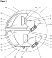
- the Fig.3 shows the ventilation unit 1 in the closed position with closed air ducts 16.
- the deflection axes 8 were moved to the left within the respective recess 10 via the rotary movement of the motor shaft 7 of the servo motor 6, which was converted into a translatory movement with the help of the angle joints 9.
- the servo motors 6 are briefly operated using electricity. After the closed position is reached, this is held without electricity again.
- the connectors 12 with the sealing plates 11 were guided within the sealing plate guide 13 over the air duct openings 17.
- the ends of the sealing plates 11 facing the container side wall 3 each lie on the upper air duct edge 18 and couple closely to the closing stop 14 of the side wall 3, which limits the leftward movement and brings it to a stop.
- the air ducts 16 are completely closed, the sealing plates 11 are in a rest position.
- the angle joints 9 of the deflection axes 8 form an obtuse angle of less than 180° in order to ensure an uninterrupted movement back to the starting position at all times.
- the deflection axes 8 pull the sealing plates 11 to the right, converting the rotary movement of the motors 6 into a translatory movement. This movement is limited by the opening stops 15 of the sealing plate guide 13, so that the sealing flaps are again transferred to a second (open) rest position.
- Ventilation unit 1 Housing 3 Side wall 4 first end of the housing 5 second end of the housing 6 Motor 7 Motor shaft 8 Deflection axis 9 Angle joint 10 Recess 11 Sealing plate (flap) 12 Connector 13 Sealing plate guide 14 Closing stop 15 Opening stop 16 Air duct 17 Air duct opening 18 Upper air duct edge
Landscapes
- Engineering & Computer Science (AREA)
- Chemical & Material Sciences (AREA)
- Combustion & Propulsion (AREA)
- Mechanical Engineering (AREA)
- General Engineering & Computer Science (AREA)
- Air-Flow Control Members (AREA)
- Ventilation (AREA)
Claims (10)
- Appareil de ventilation (1) comprenant au moins un ventilateur et un boîtier (2) qui présente des canaux d'air (16) avec des ouvertures de conduit d'air (17) pour l'amenée d'air frais et l'évacuation d'air vicié, qui mènent d'une première extrémité du boîtier (4) à une deuxième extrémité du boîtier (5), dans lequel les ouvertures de conduit d'air (17) se trouvent à la deuxième extrémité du boîtier (5) et sont configurées pour pouvoir être fermées ou ouvertes au moyen de plaques d'étanchéité (11), et dans lequel l'appareil de ventilation (1) présente au moins un moteur (6) pour activer des axes de renvoi (8) se trouvant dans le boîtier (2), qui déplacent les plaques d'étanchéité (11) au moyen d'un mouvement de translation dans une position de fermeture ou d'ouverture, caractérisé en ce que le boîtier (2) est constitué de mousse de particules de matière plastique.
- Appareil de ventilation selon la revendication 1, caractérisé en ce que les axes de renvoi (8) présentent au moins une articulation angulaire (9) et déplacent une plaque d'étanchéité (11).
- Appareil de ventilation selon la revendication 1 ou 2, caractérisé en ce que chaque plaque d'étanchéité (11) est positionnée dans un guide de plaque d'étanchéité (13).
- Appareil de ventilation selon les revendications 1 à 3, caractérisé en ce que chaque guide de plaque d'étanchéité (13) comporte une butée de fermeture (14) et une butée d'ouverture (15) qui limitent le déplacement des plaques d'étanchéité (11).
- Appareil de ventilation selon l'une des revendications 1 à 4, caractérisé en ce que le boîtier (2) comporte des évidements (10) autorisant le déplacement des axes de renvoi (8) et formant au moins un guide de plaque d'étanchéité (13).
- Appareil de ventilation selon l'une des revendications 1 à 5, caractérisé en ce que les plaques d'étanchéité (11) sont en mousse de particules de matière plastique.
- Appareil de ventilation selon l'une des revendications 1 à 6, caractérisé en ce que le moteur (6) est un servomoteur.
- Appareil de ventilation selon l'une des revendications 1 à 7, caractérisé en ce que le mouvement de rotation du moteur (6) est transformé en un mouvement de translation des plaques d'étanchéité (11) par l'intermédiaire d'axes de renvoi (8).
- Appareil de ventilation selon l'une des revendications 1 à 8, caractérisé en ce que l'appareil de ventilation comporte des dispositifs de mesure de la température et/ou de la vitesse de l'air et/ou de l'humidité de l'air et/ou de la qualité de l'air.
- Appareil de ventilation selon la revendication 9, caractérisé en ce que l'appareil de ventilation comporte une unité de commande reliée aux dispositifs de mesure pour, lorsque des seuils spécifiques sont atteints, commander le moteur (6) pour actionner des axes de renvoi (8) afin de générer une ouverture ou une fermeture des plaques d'étanchéité (11).
Applications Claiming Priority (1)
| Application Number | Priority Date | Filing Date | Title |
|---|---|---|---|
| DE202021003896.5U DE202021003896U1 (de) | 2021-12-29 | 2021-12-29 | Lüftungsgerät |
Publications (2)
| Publication Number | Publication Date |
|---|---|
| EP4206552A1 EP4206552A1 (fr) | 2023-07-05 |
| EP4206552B1 true EP4206552B1 (fr) | 2024-09-11 |
Family
ID=80267065
Family Applications (1)
| Application Number | Title | Priority Date | Filing Date |
|---|---|---|---|
| EP22181309.0A Active EP4206552B1 (fr) | 2021-12-29 | 2022-06-27 | Appareil d'aération |
Country Status (3)
| Country | Link |
|---|---|
| EP (1) | EP4206552B1 (fr) |
| DE (1) | DE202021003896U1 (fr) |
| PL (1) | PL4206552T3 (fr) |
Families Citing this family (1)
| Publication number | Priority date | Publication date | Assignee | Title |
|---|---|---|---|---|
| CN114738894B (zh) * | 2022-05-07 | 2024-03-15 | 海景建设工程有限公司 | 一种建筑节能通风装置 |
Family Cites Families (6)
| Publication number | Priority date | Publication date | Assignee | Title |
|---|---|---|---|---|
| DE2110861C3 (de) * | 1971-03-08 | 1980-01-10 | Gretsch-Unitas Gmbh Baubeschlagfabrik, 7000 Stuttgart | Schieberlüftung |
| DE8301708U1 (de) * | 1983-01-22 | 1983-06-09 | Gretsch-Unitas Gmbh Baubeschlaege, 7257 Ditzingen, De | Lueftungsvorrichtung |
| DE102004029256B4 (de) * | 2004-06-17 | 2007-03-01 | Schiedel Gmbh & Co. | Einbaublock und Einbausatz zum Einbau einer Belüftungsvorrichtung in eine Wand |
| DE102011013944A1 (de) | 2011-03-14 | 2012-09-20 | Stiebel Eltron Gmbh & Co. Kg | Lüftungsgerät mit taupunktgesteuerter Zwangslüftung |
| DE202012010671U1 (de) * | 2012-05-16 | 2012-12-17 | Ltg Aktiengesellschaft | Lufttechnisches Gerät zur Be- und Entlüftung |
| DE102014108852A1 (de) * | 2014-06-25 | 2016-01-21 | Manfred Lusch | Belüftungsvorrichtung |
-
2021
- 2021-12-29 DE DE202021003896.5U patent/DE202021003896U1/de active Active
-
2022
- 2022-06-27 PL PL22181309.0T patent/PL4206552T3/pl unknown
- 2022-06-27 EP EP22181309.0A patent/EP4206552B1/fr active Active
Also Published As
| Publication number | Publication date |
|---|---|
| EP4206552A1 (fr) | 2023-07-05 |
| PL4206552T3 (pl) | 2025-02-10 |
| DE202021003896U1 (de) | 2022-01-31 |
Similar Documents
| Publication | Publication Date | Title |
|---|---|---|
| DE3112394C2 (fr) | ||
| EP2325573A2 (fr) | Dispositif d'aération et d'évacuation d'air pour un bâtiment | |
| DE202017103341U1 (de) | Ventilationsanlage | |
| EP4206552B1 (fr) | Appareil d'aération | |
| DE10010817A1 (de) | Raumlüftungsvorrichtung | |
| DE202012103631U1 (de) | Vorrichtung zum wärme- und feuchtigkeitsregulierenden Belüften eines Innenraums | |
| DE2232482C2 (de) | Lüftungsanlage | |
| DE202022100099U1 (de) | Lüftungseinrichtung mit Wärmespeicher mit Phasenumwandlung für ein Gebäude | |
| DE102005011222A1 (de) | Lüftungsanlage | |
| EP0951630B1 (fr) | Procede d'aeration d'un local et dispositif pour mettre en oeuvre ledit procede | |
| DE202009012561U1 (de) | Absperrvorrichtung für eine Lüftungsdurchbrechung in einer Gebäudewand | |
| DE102013114085A1 (de) | Lüftungsgerät zur Raumlüftung | |
| DE10128379A1 (de) | Vorrichtung zur dezentralen Belüftung eines Raumes und Lüftungsanlage für mehrere Räume | |
| DE102009017053A1 (de) | Wärmetauschervorrichtung | |
| DE102006014104B4 (de) | Raumlüftungsvorrichtung | |
| EP2792961B1 (fr) | Module d'échangeur de chaleur | |
| DE202021103141U1 (de) | Rollladenkastenanordnung | |
| DE19639128A1 (de) | Lüftungswärmetauscher | |
| EP2447615B1 (fr) | Dispositif de ventilation de pièce décentralisé doté d'une récupération de chaleur | |
| DE102015112065B4 (de) | Verfahren zum Abfördern von Luft | |
| EP4640986A1 (fr) | Système de ventilation décentralisé | |
| DE10053509A1 (de) | Raumlüftungssystem für Gebäudesammellüftungsanlagen unter Einsatz von Rohrleitungssystemen und Verfahren zu seiner Anwendung | |
| DE3023531A1 (de) | Vorrichtung zum beheizen, kuehlen und lueften von raeumen | |
| DE102005017264A1 (de) | Innenvorsatzfenster mit Zwangslüftungselement | |
| EP2182300B1 (fr) | Dispositif d'installation pour systèmes d'aération de pièces décentralisés |
Legal Events
| Date | Code | Title | Description |
|---|---|---|---|
| PUAI | Public reference made under article 153(3) epc to a published international application that has entered the european phase |
Free format text: ORIGINAL CODE: 0009012 |
|
| STAA | Information on the status of an ep patent application or granted ep patent |
Free format text: STATUS: THE APPLICATION HAS BEEN PUBLISHED |
|
| AK | Designated contracting states |
Kind code of ref document: A1 Designated state(s): AL AT BE BG CH CY CZ DE DK EE ES FI FR GB GR HR HU IE IS IT LI LT LU LV MC MK MT NL NO PL PT RO RS SE SI SK SM TR |
|
| STAA | Information on the status of an ep patent application or granted ep patent |
Free format text: STATUS: REQUEST FOR EXAMINATION WAS MADE |
|
| 17P | Request for examination filed |
Effective date: 20231107 |
|
| RBV | Designated contracting states (corrected) |
Designated state(s): AL AT BE BG CH CY CZ DE DK EE ES FI FR GB GR HR HU IE IS IT LI LT LU LV MC MK MT NL NO PL PT RO RS SE SI SK SM TR |
|
| GRAP | Despatch of communication of intention to grant a patent |
Free format text: ORIGINAL CODE: EPIDOSNIGR1 |
|
| STAA | Information on the status of an ep patent application or granted ep patent |
Free format text: STATUS: GRANT OF PATENT IS INTENDED |
|
| RIC1 | Information provided on ipc code assigned before grant |
Ipc: F24F 13/02 20060101ALI20240311BHEP Ipc: F24F 13/24 20060101ALI20240311BHEP Ipc: F24F 7/08 20060101ALI20240311BHEP Ipc: F24F 13/12 20060101AFI20240311BHEP |
|
| INTG | Intention to grant announced |
Effective date: 20240416 |
|
| GRAS | Grant fee paid |
Free format text: ORIGINAL CODE: EPIDOSNIGR3 |
|
| GRAA | (expected) grant |
Free format text: ORIGINAL CODE: 0009210 |
|
| STAA | Information on the status of an ep patent application or granted ep patent |
Free format text: STATUS: THE PATENT HAS BEEN GRANTED |
|
| AK | Designated contracting states |
Kind code of ref document: B1 Designated state(s): AL AT BE BG CH CY CZ DE DK EE ES FI FR GB GR HR HU IE IS IT LI LT LU LV MC MK MT NL NO PL PT RO RS SE SI SK SM TR |
|
| REG | Reference to a national code |
Ref country code: GB Ref legal event code: FG4D Free format text: NOT ENGLISH |
|
| REG | Reference to a national code |
Ref country code: CH Ref legal event code: EP |
|
| REG | Reference to a national code |
Ref country code: DE Ref legal event code: R096 Ref document number: 502022001645 Country of ref document: DE |
|
| REG | Reference to a national code |
Ref country code: IE Ref legal event code: FG4D Free format text: LANGUAGE OF EP DOCUMENT: GERMAN |
|
| REG | Reference to a national code |
Ref country code: NL Ref legal event code: FP |
|
| REG | Reference to a national code |
Ref country code: LT Ref legal event code: MG9D |
|
| PG25 | Lapsed in a contracting state [announced via postgrant information from national office to epo] |
Ref country code: NO Free format text: LAPSE BECAUSE OF FAILURE TO SUBMIT A TRANSLATION OF THE DESCRIPTION OR TO PAY THE FEE WITHIN THE PRESCRIBED TIME-LIMIT Effective date: 20241211 |
|
| PG25 | Lapsed in a contracting state [announced via postgrant information from national office to epo] |
Ref country code: GR Free format text: LAPSE BECAUSE OF FAILURE TO SUBMIT A TRANSLATION OF THE DESCRIPTION OR TO PAY THE FEE WITHIN THE PRESCRIBED TIME-LIMIT Effective date: 20241212 Ref country code: FI Free format text: LAPSE BECAUSE OF FAILURE TO SUBMIT A TRANSLATION OF THE DESCRIPTION OR TO PAY THE FEE WITHIN THE PRESCRIBED TIME-LIMIT Effective date: 20240911 |
|
| PG25 | Lapsed in a contracting state [announced via postgrant information from national office to epo] |
Ref country code: BG Free format text: LAPSE BECAUSE OF FAILURE TO SUBMIT A TRANSLATION OF THE DESCRIPTION OR TO PAY THE FEE WITHIN THE PRESCRIBED TIME-LIMIT Effective date: 20240911 |
|
| PG25 | Lapsed in a contracting state [announced via postgrant information from national office to epo] |
Ref country code: LV Free format text: LAPSE BECAUSE OF FAILURE TO SUBMIT A TRANSLATION OF THE DESCRIPTION OR TO PAY THE FEE WITHIN THE PRESCRIBED TIME-LIMIT Effective date: 20240911 |
|
| PG25 | Lapsed in a contracting state [announced via postgrant information from national office to epo] |
Ref country code: HR Free format text: LAPSE BECAUSE OF FAILURE TO SUBMIT A TRANSLATION OF THE DESCRIPTION OR TO PAY THE FEE WITHIN THE PRESCRIBED TIME-LIMIT Effective date: 20240911 |
|
| PG25 | Lapsed in a contracting state [announced via postgrant information from national office to epo] |
Ref country code: RS Free format text: LAPSE BECAUSE OF FAILURE TO SUBMIT A TRANSLATION OF THE DESCRIPTION OR TO PAY THE FEE WITHIN THE PRESCRIBED TIME-LIMIT Effective date: 20241211 Ref country code: ES Free format text: LAPSE BECAUSE OF FAILURE TO SUBMIT A TRANSLATION OF THE DESCRIPTION OR TO PAY THE FEE WITHIN THE PRESCRIBED TIME-LIMIT Effective date: 20240911 |
|
| PG25 | Lapsed in a contracting state [announced via postgrant information from national office to epo] |
Ref country code: RS Free format text: LAPSE BECAUSE OF FAILURE TO SUBMIT A TRANSLATION OF THE DESCRIPTION OR TO PAY THE FEE WITHIN THE PRESCRIBED TIME-LIMIT Effective date: 20241211 Ref country code: NO Free format text: LAPSE BECAUSE OF FAILURE TO SUBMIT A TRANSLATION OF THE DESCRIPTION OR TO PAY THE FEE WITHIN THE PRESCRIBED TIME-LIMIT Effective date: 20241211 Ref country code: LV Free format text: LAPSE BECAUSE OF FAILURE TO SUBMIT A TRANSLATION OF THE DESCRIPTION OR TO PAY THE FEE WITHIN THE PRESCRIBED TIME-LIMIT Effective date: 20240911 Ref country code: HR Free format text: LAPSE BECAUSE OF FAILURE TO SUBMIT A TRANSLATION OF THE DESCRIPTION OR TO PAY THE FEE WITHIN THE PRESCRIBED TIME-LIMIT Effective date: 20240911 Ref country code: GR Free format text: LAPSE BECAUSE OF FAILURE TO SUBMIT A TRANSLATION OF THE DESCRIPTION OR TO PAY THE FEE WITHIN THE PRESCRIBED TIME-LIMIT Effective date: 20241212 Ref country code: FI Free format text: LAPSE BECAUSE OF FAILURE TO SUBMIT A TRANSLATION OF THE DESCRIPTION OR TO PAY THE FEE WITHIN THE PRESCRIBED TIME-LIMIT Effective date: 20240911 Ref country code: ES Free format text: LAPSE BECAUSE OF FAILURE TO SUBMIT A TRANSLATION OF THE DESCRIPTION OR TO PAY THE FEE WITHIN THE PRESCRIBED TIME-LIMIT Effective date: 20240911 Ref country code: BG Free format text: LAPSE BECAUSE OF FAILURE TO SUBMIT A TRANSLATION OF THE DESCRIPTION OR TO PAY THE FEE WITHIN THE PRESCRIBED TIME-LIMIT Effective date: 20240911 |
|
| PG25 | Lapsed in a contracting state [announced via postgrant information from national office to epo] |
Ref country code: IS Free format text: LAPSE BECAUSE OF FAILURE TO SUBMIT A TRANSLATION OF THE DESCRIPTION OR TO PAY THE FEE WITHIN THE PRESCRIBED TIME-LIMIT Effective date: 20250111 Ref country code: PT Free format text: LAPSE BECAUSE OF FAILURE TO SUBMIT A TRANSLATION OF THE DESCRIPTION OR TO PAY THE FEE WITHIN THE PRESCRIBED TIME-LIMIT Effective date: 20250113 |
|
| PG25 | Lapsed in a contracting state [announced via postgrant information from national office to epo] |
Ref country code: SM Free format text: LAPSE BECAUSE OF FAILURE TO SUBMIT A TRANSLATION OF THE DESCRIPTION OR TO PAY THE FEE WITHIN THE PRESCRIBED TIME-LIMIT Effective date: 20240911 Ref country code: RO Free format text: LAPSE BECAUSE OF FAILURE TO SUBMIT A TRANSLATION OF THE DESCRIPTION OR TO PAY THE FEE WITHIN THE PRESCRIBED TIME-LIMIT Effective date: 20240911 |
|
| PG25 | Lapsed in a contracting state [announced via postgrant information from national office to epo] |
Ref country code: EE Free format text: LAPSE BECAUSE OF FAILURE TO SUBMIT A TRANSLATION OF THE DESCRIPTION OR TO PAY THE FEE WITHIN THE PRESCRIBED TIME-LIMIT Effective date: 20240911 |
|
| PG25 | Lapsed in a contracting state [announced via postgrant information from national office to epo] |
Ref country code: IT Free format text: LAPSE BECAUSE OF FAILURE TO SUBMIT A TRANSLATION OF THE DESCRIPTION OR TO PAY THE FEE WITHIN THE PRESCRIBED TIME-LIMIT Effective date: 20240911 Ref country code: SK Free format text: LAPSE BECAUSE OF FAILURE TO SUBMIT A TRANSLATION OF THE DESCRIPTION OR TO PAY THE FEE WITHIN THE PRESCRIBED TIME-LIMIT Effective date: 20240911 |
|
| REG | Reference to a national code |
Ref country code: DE Ref legal event code: R097 Ref document number: 502022001645 Country of ref document: DE |
|
| PGFP | Annual fee paid to national office [announced via postgrant information from national office to epo] |
Ref country code: PL Payment date: 20250624 Year of fee payment: 4 Ref country code: DE Payment date: 20250618 Year of fee payment: 4 |
|
| PG25 | Lapsed in a contracting state [announced via postgrant information from national office to epo] |
Ref country code: DK Free format text: LAPSE BECAUSE OF FAILURE TO SUBMIT A TRANSLATION OF THE DESCRIPTION OR TO PAY THE FEE WITHIN THE PRESCRIBED TIME-LIMIT Effective date: 20240911 |
|
| PGFP | Annual fee paid to national office [announced via postgrant information from national office to epo] |
Ref country code: NL Payment date: 20250618 Year of fee payment: 4 |
|
| PGFP | Annual fee paid to national office [announced via postgrant information from national office to epo] |
Ref country code: FR Payment date: 20250627 Year of fee payment: 4 |
|
| PLBE | No opposition filed within time limit |
Free format text: ORIGINAL CODE: 0009261 |
|
| STAA | Information on the status of an ep patent application or granted ep patent |
Free format text: STATUS: NO OPPOSITION FILED WITHIN TIME LIMIT |
|
| PGFP | Annual fee paid to national office [announced via postgrant information from national office to epo] |
Ref country code: AT Payment date: 20250721 Year of fee payment: 4 |
|
| PGFP | Annual fee paid to national office [announced via postgrant information from national office to epo] |
Ref country code: CZ Payment date: 20250625 Year of fee payment: 4 |
|
| 26N | No opposition filed |
Effective date: 20250612 |
|
| PG25 | Lapsed in a contracting state [announced via postgrant information from national office to epo] |
Ref country code: SE Free format text: LAPSE BECAUSE OF FAILURE TO SUBMIT A TRANSLATION OF THE DESCRIPTION OR TO PAY THE FEE WITHIN THE PRESCRIBED TIME-LIMIT Effective date: 20240911 |
|
| PGFP | Annual fee paid to national office [announced via postgrant information from national office to epo] |
Ref country code: CH Payment date: 20250701 Year of fee payment: 4 |
|
| PG25 | Lapsed in a contracting state [announced via postgrant information from national office to epo] |
Ref country code: MC Free format text: LAPSE BECAUSE OF FAILURE TO SUBMIT A TRANSLATION OF THE DESCRIPTION OR TO PAY THE FEE WITHIN THE PRESCRIBED TIME-LIMIT Effective date: 20240911 |
|
| PG25 | Lapsed in a contracting state [announced via postgrant information from national office to epo] |
Ref country code: LU Free format text: LAPSE BECAUSE OF NON-PAYMENT OF DUE FEES Effective date: 20250627 |
|
| REG | Reference to a national code |
Ref country code: BE Ref legal event code: MM Effective date: 20250630 |
|
| PG25 | Lapsed in a contracting state [announced via postgrant information from national office to epo] |
Ref country code: IE Free format text: LAPSE BECAUSE OF NON-PAYMENT OF DUE FEES Effective date: 20250627 |
|
| PG25 | Lapsed in a contracting state [announced via postgrant information from national office to epo] |
Ref country code: BE Free format text: LAPSE BECAUSE OF NON-PAYMENT OF DUE FEES Effective date: 20250630 |