EP4206552B1 - Ventilation device - Google Patents
Ventilation device Download PDFInfo
- Publication number
- EP4206552B1 EP4206552B1 EP22181309.0A EP22181309A EP4206552B1 EP 4206552 B1 EP4206552 B1 EP 4206552B1 EP 22181309 A EP22181309 A EP 22181309A EP 4206552 B1 EP4206552 B1 EP 4206552B1
- Authority
- EP
- European Patent Office
- Prior art keywords
- ventilation device
- housing
- air
- ventilation
- sealing plate
- Prior art date
- Legal status (The legal status is an assumption and is not a legal conclusion. Google has not performed a legal analysis and makes no representation as to the accuracy of the status listed.)
- Active
Links
Images


Classifications
-
- F—MECHANICAL ENGINEERING; LIGHTING; HEATING; WEAPONS; BLASTING
- F24—HEATING; RANGES; VENTILATING
- F24F—AIR-CONDITIONING; AIR-HUMIDIFICATION; VENTILATION; USE OF AIR CURRENTS FOR SCREENING
- F24F7/00—Ventilation
- F24F7/04—Ventilation with ducting systems, e.g. by double walls; with natural circulation
- F24F7/06—Ventilation with ducting systems, e.g. by double walls; with natural circulation with forced air circulation, e.g. by fan positioning of a ventilator in or against a conduit
- F24F7/08—Ventilation with ducting systems, e.g. by double walls; with natural circulation with forced air circulation, e.g. by fan positioning of a ventilator in or against a conduit with separate ducts for supplied and exhausted air with provisions for reversal of the input and output systems
-
- F—MECHANICAL ENGINEERING; LIGHTING; HEATING; WEAPONS; BLASTING
- F24—HEATING; RANGES; VENTILATING
- F24F—AIR-CONDITIONING; AIR-HUMIDIFICATION; VENTILATION; USE OF AIR CURRENTS FOR SCREENING
- F24F13/00—Details common to, or for air-conditioning, air-humidification, ventilation or use of air currents for screening
- F24F13/02—Ducting arrangements
- F24F13/0263—Insulation for air ducts
-
- F—MECHANICAL ENGINEERING; LIGHTING; HEATING; WEAPONS; BLASTING
- F24—HEATING; RANGES; VENTILATING
- F24F—AIR-CONDITIONING; AIR-HUMIDIFICATION; VENTILATION; USE OF AIR CURRENTS FOR SCREENING
- F24F13/00—Details common to, or for air-conditioning, air-humidification, ventilation or use of air currents for screening
- F24F13/08—Air-flow control members, e.g. louvres, grilles, flaps or guide plates
- F24F13/10—Air-flow control members, e.g. louvres, grilles, flaps or guide plates movable, e.g. dampers
- F24F13/12—Air-flow control members, e.g. louvres, grilles, flaps or guide plates movable, e.g. dampers built up of sliding members
-
- F—MECHANICAL ENGINEERING; LIGHTING; HEATING; WEAPONS; BLASTING
- F24—HEATING; RANGES; VENTILATING
- F24F—AIR-CONDITIONING; AIR-HUMIDIFICATION; VENTILATION; USE OF AIR CURRENTS FOR SCREENING
- F24F13/00—Details common to, or for air-conditioning, air-humidification, ventilation or use of air currents for screening
- F24F13/24—Means for preventing or suppressing noise
-
- F—MECHANICAL ENGINEERING; LIGHTING; HEATING; WEAPONS; BLASTING
- F24—HEATING; RANGES; VENTILATING
- F24F—AIR-CONDITIONING; AIR-HUMIDIFICATION; VENTILATION; USE OF AIR CURRENTS FOR SCREENING
- F24F7/00—Ventilation
- F24F2007/0025—Ventilation using vent ports in a wall
Definitions
- the invention is based on the object of improving a decentralized ventilation device.
- a ventilation device is to be created that has a high level of efficiency with increased air exchange and insulation against temperatures and noise while requiring little space.
- Temperature and/or humidity sensors are provided to determine a dew point of the air and to use a control unit to detect that icing could occur in the ventilation unit so that the sealing plates can be activated in good time to prevent icing.
- Wind speed sensors are also provided to determine a critical value using a control unit at which the flaps can be activated in good time to protect the system against strong wind speeds.
- Decentralized ventilation is particularly suitable for existing properties to ventilate living spaces.
- Controlled ventilation in living spaces has numerous advantages.
- a consistently high air quality creates a consistently good indoor climate.
- the building shell of new buildings or subsequently sealed existing properties is so tight that sufficient living space ventilation is no longer guaranteed.
- Regular and efficient window ventilation is usually not possible for the residents themselves. Instead, living spaces are often inadequately ventilated or the windows are tilted for long periods of time so that warm room air can constantly escape. This leads to a higher risk of burglary or, depending on the location of the property, to greater noise pollution or draughts. While permanently tilting the windows lets heat into the building in summer, in the colder months it leads to significantly higher heating costs due to heat loss due to ventilation.
- Insufficient ventilation poses a great risk of damage caused by moisture and mold growth if room air enriched with water vapor is not removed in a controlled manner. This moisture can build up permanently on wall surfaces and lead to mold or even structural damage.
- Controlled living space ventilation is therefore advisable because it ensures suitable ventilation regardless of the user and, through the regular exchange of used air for fresh air, creates a consistently good indoor climate and protects the building shell from damage. In this way, the quality, temperature and humidity of the indoor air can be conditioned to suit the use of the rooms by the people present.
- the ventilation systems can also be equipped with filters to prevent allergens, pollen and particles from the outside air from entering the respective living space. If they are equipped with heat exchangers, such systems can even extract heat from the exhaust air in order to transfer it to the fresh air that is drawn in and then feed it back into the building.
- decentralized living space ventilation with ventilation units that can be retrofitted is particularly advantageous for existing properties.
- Decentralized ventilation systems are well known.
- EN 10 2011 013 944 A1 a ventilation device designed for wall installation that can directly supply outside air into the building interior and direct exhaust air to the outside.
- Such devices can be installed in the building's outer wall.
- Individual living spaces or entire residential units can be equipped with decentralized devices.
- a decentralized ventilation system can often be tailored to the residents' specific needs more flexibly and inexpensively. Maintenance and cleaning or changing the filters also require significantly less effort.
- a disadvantage compared to central ventilation systems is the increased noise level of decentralized ventilation units, which is why they are preferably covered with insulating materials against noise, but also against temperatures, after use inside the boreholes before the masonry is closed.
- a ventilation device in which a heat exchanger is arranged in a housing.
- the housing has a hinged front wall, which provides access to the heat exchanger so that it can be easily replaced.
- the front wall also contains air inlets that can be closed using a slider integrated into the front wall.
- the housing especially the front wall, must be very stable. To ensure the compactness of the housing, it is therefore made of sturdy metal plates.
- EN 10 2004 029 256 A1 describes a built-in block for installing a ventilation device.
- the separate built-in block is designed to be inserted into a masonry during the shell construction phase and then to enable a ventilation device to be easily installed in the finished masonry.
- the invention is based on the object of providing a decentralized ventilation device with a housing which has advantageous properties such as low weight, insulating, leak-tight and soundproofing properties, without the need for subsequent cladding within the borehole.
- a decentralized ventilation unit is to be provided which has a significantly lower noise level and requires significantly less space while being highly efficient and providing increased air exchange.
- the plastic particle foam represents an insulating layer with integrated sound, heat and cold insulation and consists of plastic or foam particles, for example made of EPP (expanded polypropylene) or EPS (expanded polystyrene). Subsequent insulation and sealing of the ventilation unit is therefore no longer necessary. The lower weight of the unit makes installation easier.
- the ventilation device has a housing with at least two air ducts through which outside air can get into the building interior and inside air can get out.
- the housing is equipped with a sealing plate guide that leads to the air ducts and in which flap-like sealing plates are mounted so that they can assume a position that closes or opens an air duct.
- the sealing plate guide also opens into a recess in which deflection axes are mounted, which are each connected via a connector to a sealing plate and at the opposite end to a servo motor.
- the deflection axes have angle joints via which the rotary movement of the motor shaft of the servo motor is converted into a translatory movement of the sealing plates.
- the sealing flaps of the ventilation device according to the invention When opened, the sealing flaps of the ventilation device according to the invention are pushed out of the ventilation duct with a sliding movement of the deflection axes, i.e. they are located outside the air flow, so that they do not cause increased noise as a disruptive factor, as is the case with known ventilation devices.
- the space no longer required for pivoting the sealing plates makes it possible to design the ventilation device according to the invention with significantly larger ventilation duct diameters, which allow a higher air flow without significant resistance, which leads to an improved performance of the ventilation device.
- the sealing flaps in the ventilation device according to the invention are held in the open or closed position without power, which leads to lower energy consumption.
- the housing of the ventilation device according to the invention can also accommodate a heater or a heat storage unit or fans, which are controlled via a control unit on the basis of various measurement parameters such as outside temperature, inside temperature, temperature of the air flows, air quality such as CO2 value, air humidity or oxygen content.
- the measurement parameters are determined by suitable measuring devices such as sensors, analyzed and forwarded to the control unit.
- FIG.1 shows an isometric representation of a ventilation device 1 according to the invention in the open position.
- the ventilation device 1 can, for example, be installed after core drilling in an outer wall of a building and has a side wall 3 made of plastic particle foam, which forms a housing space. The side wall 3 is completely enclosed by the building wall after installation of the ventilation device 1.
- the ventilation device 1 has a first end 4, which is positioned on the inner wall, and a second end 5, which is positioned on the outer wall of the building.
- these two ends of the housing 2 are also made of plastic particle foam.
- exhaust air is discharged from the room through a first air duct 16 located in the housing 2 and guided out of the building via the second end 5.
- Supply air enters the building through the second end 5 through a second air duct 16 located in the housing 2 and is guided to the interior via the first end 4.
- the fan In the interior of the housing between the first and second ends, in a chamber adjacent to the air ducts 16 (not shown), there is the fan and, as required, devices such as a heating element, filter, control unit or heat exchanger.
- the sealing flaps 11 can be made of plastic or another suitable material, but preferably also of plastic particle foam.
- the illustration shows the air ducts 16 in the open position, in which the sealing flaps 11 are located within a sealing plate guide 13 on the right-hand opening stop 15.
- the housing 2 can be equipped with a closable housing opening that allows access to the housing interior for maintenance or repair work.
- the housing 2 can consist of several individual parts that can be inserted into one another and fixed, for example by screwing, locking or welding.
- Fig. 2 shows a top view of the second end 5 of the ventilation device 1 facing the outer wall of the building in the open position with the ventilation ducts open. It is clearly visible that the sealing plates 11 are completely outside the air flow and therefore do not represent a disruptive factor that could lead to noise generation and noise pollution. The usable length is increased because there is no need for the sealing plates 11 to swivel out in a rotary manner, which would require more space.
- Motors 6 are positioned in the recesses 10 of the housing 2, each of which is connected to a deflection axis 8. These are two servo motors. The motors 6 do not require any power to hold this position.
- the deflection axes 8 are each formed by an angle joint 9, each of which has a rod that is connected to a servo motor 6, and another rod that is connected to a connector 12.
- the connectors 12 are each connected to a sealing plate 11 and are suitable for moving this sealing plate 11 within a sealing plate guide 13. It is also conceivable to design the sealing plate 11 and connector 12 as a single piece.
- the deflection axes 8 are located at an almost right angle, which means that they require little space in the associated recess 10.
- the sealing plate guide 13 opens into an air duct opening 17, which is arranged on the side wall 3 of the housing 2.
- the air duct openings 17 have an upper air duct edge 18 that protrudes from the housing wall.
- the sealing plate guide 13 has a closing stop 14 at the end located on the side wall 3, which is positioned so that the sealing plate 11 can rest on the upper air duct edge 18 in the closed position with its end facing the housing wall.
- the sealing plate guide 13 has an opening stop 15 that limits the position of the sealing plates 11 towards the interior of the housing 2.
- the sealing plates 11 have an end facing the side wall 3 that is adapted to the geometry of the side wall 3. In the example, this is a partial segment of a circle.
- wings are formed at the top and bottom, which rest against the opening stop 15 of the sealing plate guide 13. This position of the sealing plates 11 creates a complete opening of the air ducts 16.
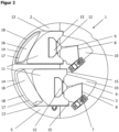
- the Fig.3 shows the ventilation unit 1 in the closed position with closed air ducts 16.
- the deflection axes 8 were moved to the left within the respective recess 10 via the rotary movement of the motor shaft 7 of the servo motor 6, which was converted into a translatory movement with the help of the angle joints 9.
- the servo motors 6 are briefly operated using electricity. After the closed position is reached, this is held without electricity again.
- the connectors 12 with the sealing plates 11 were guided within the sealing plate guide 13 over the air duct openings 17.
- the ends of the sealing plates 11 facing the container side wall 3 each lie on the upper air duct edge 18 and couple closely to the closing stop 14 of the side wall 3, which limits the leftward movement and brings it to a stop.
- the air ducts 16 are completely closed, the sealing plates 11 are in a rest position.
- the angle joints 9 of the deflection axes 8 form an obtuse angle of less than 180° in order to ensure an uninterrupted movement back to the starting position at all times.
- the deflection axes 8 pull the sealing plates 11 to the right, converting the rotary movement of the motors 6 into a translatory movement. This movement is limited by the opening stops 15 of the sealing plate guide 13, so that the sealing flaps are again transferred to a second (open) rest position.
- Ventilation unit 1 Housing 3 Side wall 4 first end of the housing 5 second end of the housing 6 Motor 7 Motor shaft 8 Deflection axis 9 Angle joint 10 Recess 11 Sealing plate (flap) 12 Connector 13 Sealing plate guide 14 Closing stop 15 Opening stop 16 Air duct 17 Air duct opening 18 Upper air duct edge
Landscapes
- Engineering & Computer Science (AREA)
- Chemical & Material Sciences (AREA)
- Combustion & Propulsion (AREA)
- Mechanical Engineering (AREA)
- General Engineering & Computer Science (AREA)
- Air-Flow Control Members (AREA)
- Ventilation (AREA)
Description
Der Erfindung liegt die Aufgabe zugrunde, ein dezentrales Lüftungsgerät zu verbessern. Insbesondere soll ein Lüftungsgerät geschaffen werden, das bei geringem Raumbedarf eine hohe Effizienz mit erhöhtem Luftaustausch und eine Dämmung gegen Temperaturen und Schall aufweist.The invention is based on the object of improving a decentralized ventilation device. In particular, a ventilation device is to be created that has a high level of efficiency with increased air exchange and insulation against temperatures and noise while requiring little space.
Diese Aufgabe ist mit einem Lüftungsgerät mit der Merkmalskombination nach Anspruch 1 gelöst. Die abhängigen Ansprüche definieren bevorzugte Ausgestaltungen der Erfindung.This object is achieved with a ventilation device with the combination of features according to
Temperatur- und/oder Luftfeuchtesensoren sind vorgesehen, um einen Taupunkt der Luft zu bestimmen und daraus mittels einer Steuereinheit zu detektieren, dass es im Lüftungsgerät zu einer Vereisung kommen könnte, so dass rechtzeitig die Dichtplatten betätigt werden, um einer Vereisung vorzubeugen. Auch sind Windgeschwindigl<eitssensoren vorgesehen, um einen kritischen Wert mittels einer Steuereinheit zu bestimmen, zu dem rechtzeitig die Klappen betätigt werden, um das System gegen starke Windgeschwindigkeiten zu schützen.Temperature and/or humidity sensors are provided to determine a dew point of the air and to use a control unit to detect that icing could occur in the ventilation unit so that the sealing plates can be activated in good time to prevent icing. Wind speed sensors are also provided to determine a critical value using a control unit at which the flaps can be activated in good time to protect the system against strong wind speeds.
Eine dezentrale Lüftung ist besonders für Bestandsimmobilien geeignet, um Wohnräume zu belüften.Decentralized ventilation is particularly suitable for existing properties to ventilate living spaces.
Eine kontrollierte Wohnraumlüftung hat zahlreiche Vorteile. Eine konstant hohe Luftqualität erzeugt ein konstant gutes Raumklima. Früher passierte der natürliche Luftwechsel über Fugen und Undichtigkeiten in Fenstern, Türen oder Wänden. Heutzutage ist bei Neubauten oder nachträglich abgedichteten Bestandsimmobilien die Gebäude- hülle so dicht, dass eine ausreichende Wohnraumlüftung nicht mehr gewährleistet ist. Eine regelmäßige und effiziente Fensterlüftung ist in der Regel von den Bewohnern selbst nicht zu leisten. Häufig wird statt- dessen in Wohnräumen nur unzureichend gelüftet oder die Fenster werden über längere Zeiträume gekippt, so dass ständig warme Raumluft entweichen kann. Das führt zu einem höheren Einbruchrisil<o bzw. je nach Lage der Immobilie zu höherer Lärmbelastung oder Zuglufterscheinungen. Während das dauerhafte Kippen der Fenster im Sommer die Hitze in das Gebäude lässt, führt es in den kälteren Monaten zu deutlich erhöhten Heizkosten durch lüftungsbedingte Wärmeverluste.Controlled ventilation in living spaces has numerous advantages. A consistently high air quality creates a consistently good indoor climate. In the past, the natural Air exchange via joints and leaks in windows, doors or walls. Nowadays, the building shell of new buildings or subsequently sealed existing properties is so tight that sufficient living space ventilation is no longer guaranteed. Regular and efficient window ventilation is usually not possible for the residents themselves. Instead, living spaces are often inadequately ventilated or the windows are tilted for long periods of time so that warm room air can constantly escape. This leads to a higher risk of burglary or, depending on the location of the property, to greater noise pollution or draughts. While permanently tilting the windows lets heat into the building in summer, in the colder months it leads to significantly higher heating costs due to heat loss due to ventilation.
Ein unzureichendes Lüften birgt demgegenüber eine große Gefahr für Schäden durch Feuchtigkeit und Schimmelbildung, wenn mit Wasserdampf angereicherte Raumluft nicht geregelt abgeführt wird. Diese Feuchtigkeit kann sich dauerhaft auf Wandoberflächen anlegen und zu Schimmel oder gar zu strukturellen Schäden führen.Insufficient ventilation, on the other hand, poses a great risk of damage caused by moisture and mold growth if room air enriched with water vapor is not removed in a controlled manner. This moisture can build up permanently on wall surfaces and lead to mold or even structural damage.
Eine kontrollierte Wohnraumlüftung ist deshalb angeraten, da diese nutzerunabhängig für eine geeignete Be- und Entlüftung sorgt und durch den regelmäßigen Austausch von verbrauchter gegen Frischluft ein konstant gutes Raumklima erzeugt und die Gebäudehülle vor Schäden schützt. So kann die Raumluft hinsichtlich ihrer Qualität, Temperatur und Feuchtigkeit so konditioniert werden, wie es für die Nutzung der Räume durch die anwesenden Personen erforderlich oder gewünscht ist. Auch können die Lüftungsanlagen mit Filtern ausgestattet werden, um Allergene, Pollen und Partikel aus der Außenluft vor dem Eindringen in den jeweiligen Wohnraum zu hindern. Wenn diese mit Wärmetau- scher ausgestattet sind, können solche Anlagen sogar der Abluft Wärme entziehen, um diese auf die angesaugte Frischluft zu übertragen und dem Gebäude wieder zuzuführen.Controlled living space ventilation is therefore advisable because it ensures suitable ventilation regardless of the user and, through the regular exchange of used air for fresh air, creates a consistently good indoor climate and protects the building shell from damage. In this way, the quality, temperature and humidity of the indoor air can be conditioned to suit the use of the rooms by the people present. The ventilation systems can also be equipped with filters to prevent allergens, pollen and particles from the outside air from entering the respective living space. If they are equipped with heat exchangers, such systems can even extract heat from the exhaust air in order to transfer it to the fresh air that is drawn in and then feed it back into the building.
Besonders vorteilhaft für bestehende Immobilien ist die Installation einer dezentralen Wohnraumlüftung mit Lüftungsgeräten, die sich nachträglich einbauen lassen. Dezentrale Lüftungsanlagen sind bekannt. Beispielsweise betrifft die
Während zentrale Lüftungsanlagen aufgrund ihres notwendigen Luftverteilsystems nur mit hohem Aufwand installiert werden können und sich eher für Neubauten eignen, ist dies für Bestandsimmobilien mit relativ geringem Aufwand mit dezentralen Lüftungsgeräten möglich. Außenluft und Fortluft werden so auf kurzem Weg durch die Fassade zu bzw. abgeführt, ohne dass es eines Luftkanalsystems im gesamten Gebäude bedarf. Die Wärme der Abluft kann dabei im Lüftungsgerät zurück gewonnen und direkt an die von außen einströmende Zuluft übertragen werden.While central ventilation systems can only be installed with great effort due to the air distribution system they require and are more suitable for new buildings, this can be done with relatively little effort for existing properties using decentralized ventilation units. Outside air and exhaust air are thus supplied and removed via a short route through the facade without the need for an air duct system throughout the building. The heat from the exhaust air can be recovered in the ventilation unit and transferred directly to the supply air flowing in from outside.
Nach Kernlochbohrung können solche Geräte in der Gebäudeaußenwand eingebaut werden. Es können einzelne Wohnräume aber auch komplette Wohneinheiten mit dezentralen Geräten ausgestattet werden. Eine dezentrale Lüftungsanlage kann häufig flexibler und günstiger auf die besonderen Bedürfnisse der Bewohner ausgerichtet werden. Auch die Wartung und Reinigung bzw. Wechsel der Filter sind mit deutlich geringerem Auf- wand verbunden.After core drilling, such devices can be installed in the building's outer wall. Individual living spaces or entire residential units can be equipped with decentralized devices. A decentralized ventilation system can often be tailored to the residents' specific needs more flexibly and inexpensively. Maintenance and cleaning or changing the filters also require significantly less effort.
Nachteilig im Vergleich zu zentralen Lüftungsanlagen ist ein erhöhter Geräuschpegel der dezentralen Lüftungsgeräte, weshalb diese nach Einsatz innerhalb der Bohrlöcher vorzugsweise mit Dämmmaterialien gegen Schall, aber auch gegen Temperaturen aufwändig verkleidet werden, bevor das Mauerwerk geschlossen wird.A disadvantage compared to central ventilation systems is the increased noise level of decentralized ventilation units, which is why they are preferably covered with insulating materials against noise, but also against temperatures, after use inside the boreholes before the masonry is closed.
Weiterhin ist von Nachteil, dass bekannte dezentrale Lüftungsgeräte Dichtplatten aufweisen, die von Getriebemotoren mit Drehachse betätigt werden. Solche Motoren sind zwar kostengünstig, jedoch sehr laut und benötigen viel Platz. Die Dichtplatten solcher bekannten Lüftungsgeräte schwenken bei Betätigung aus dem Gerät heraus oder nach innen, weshalb diese Systeme größeren Platz einnehmen und verhältnismäßig geringe Luftl<analdurchmesser zulassen. Die Dichtplatten sind dabei durchgehend - also im geöffneten oder im geschlossenen Zustand - dem Luftstrom ausgesetzt. Der Luftwiderstand führt deshalb zu einer größeren Geräuschkulisse.Another disadvantage is that known decentralized ventilation devices have sealing plates that are operated by geared motors with a rotating axis. Such motors are inexpensive, but very loud and take up a lot of space. The sealing plates of such known ventilation devices swing out of the device or inwards when operated, which is why these systems take up more space and allow relatively small air duct diameters. The sealing plates are constantly exposed to the air flow - whether open or closed. The air resistance therefore leads to a greater background noise.
Aus
Der Erfindung liegt die Aufgabe zugrunde, ein dezentrales Lüftungsgerät mit einem Gehäuse bereitzustellen, das vorteilhafte Eigenschaften wie beispielsweise geringes Gewicht, Isolier-, Dichtigl<eits- und Dämmungseigenschaften aufweist, ohne dass es einer nachträglichen Verkleidung innerhalb des Bohrlochs bedarf.The invention is based on the object of providing a decentralized ventilation device with a housing which has advantageous properties such as low weight, insulating, leak-tight and soundproofing properties, without the need for subsequent cladding within the borehole.
Weiterhin soll ein dezentrales Lüftungsgerät bereitgestellt werden, der eine deutlich geringere Lärmbelastung und deutlich geringeren Platz- bedarf bei hoher Effizienz mit erhöhtem Luftaustausch aufweist.Furthermore, a decentralized ventilation unit is to be provided which has a significantly lower noise level and requires significantly less space while being highly efficient and providing increased air exchange.
Diese Aufgabe wird durch die Merkmalskombination des Anspruchs 1 gelöst, wobei das Gehäuse des Lüftungsgeräts aus einem KUnststoff-- Partikelschaum hergestellt ist.This object is achieved by the combination of features of
Der I<unststoff-Partil<elschaum stellt dabei eine Isolationsschicht mit integrierter Schall-, Wärme- bzw. Kälteisolation dar und besteht aus Kunststoff- oder Schaumstoffpartikeln beispielsweise aus EPP (expandiertes Polypropylen) oder aus EPS (expandiertes Polystyrol). Eine nachträgliche Dämmung und Abdichtung des Lüftungsgerätes ist damit nicht mehr notwendig. Das geringere Gewicht des Gerätes erleichtert die Installation.The plastic particle foam represents an insulating layer with integrated sound, heat and cold insulation and consists of plastic or foam particles, for example made of EPP (expanded polypropylene) or EPS (expanded polystyrene). Subsequent insulation and sealing of the ventilation unit is therefore no longer necessary. The lower weight of the unit makes installation easier.
Das erfindungsgemäße Lüftungsgerät weist ein Gehäuse mit mindestens zwei Luftkanälen auf, in denen Außenluft in das Gebäudeinnere und Innenluft nach außen gelangen kann. Das Gehäuse ist mit einer Dichtplattenführung ausgestattet ist, die zu den Luftkanälen führt und in der klappenartige Dichtplatten so gelagert sind, dass diese eine Position einnehmen können, die einen Luftkanal schließt oder öffnet. Die Dichtplattenführung mündet außerdem in eine Ausnehmung, in der Umlenkachsen gelagert sind, die über einen Konnektor mit jeweils einer Dichtplatte und am entgegengesetzten Ende mit einem Servomotor verbunden sind. Die Umlenkachsen besitzen Winl<elgelenl<e, über die die rotatorische Bewegung der Motorwelle des Servomotors in eine translatorische Bewegung der Dichtplatten umgewandelt wird. Die Dichtklappen des erfindungsgemäßen Lüftungsgeräts werden beim Öffnen mit einer Schiebebewegung der Umlenkachsen aus dem Lüftungskanal herausgeschoben, befinden sich also außerhalb des Luftstroms, so dass sie nicht wie bei bekannten Lüftungsgeräten als Störfaktor zu verstärkter Schallentwicklung führen.The ventilation device according to the invention has a housing with at least two air ducts through which outside air can get into the building interior and inside air can get out. The housing is equipped with a sealing plate guide that leads to the air ducts and in which flap-like sealing plates are mounted so that they can assume a position that closes or opens an air duct. The sealing plate guide also opens into a recess in which deflection axes are mounted, which are each connected via a connector to a sealing plate and at the opposite end to a servo motor. The deflection axes have angle joints via which the rotary movement of the motor shaft of the servo motor is converted into a translatory movement of the sealing plates. When opened, the sealing flaps of the ventilation device according to the invention are pushed out of the ventilation duct with a sliding movement of the deflection axes, i.e. they are located outside the air flow, so that they do not cause increased noise as a disruptive factor, as is the case with known ventilation devices.
Der für ein Schwenken der Dichtplatten nicht mehr benötigte Platz, macht es möglich das erfindungsgemäße Lüftungsgeräts mit deutlich größeren Lüftungsl<analdurchmessern auszugestalten, die einen höheren Luftdurchfluss ohne erheblichen Widerstand zulassen, was zu einer verbesserten Leistungsfähigkeit des Lüftungsgeräts führt.The space no longer required for pivoting the sealing plates makes it possible to design the ventilation device according to the invention with significantly larger ventilation duct diameters, which allow a higher air flow without significant resistance, which leads to an improved performance of the ventilation device.
Außerdem werden die Dichtklappen im Gegensatz zu bekannten Lösungen beim erfindungsgemäßen Lüftungsgerät stromlos in der offenen oder geschlossenen Position gehalten, was zu einem geringeren Energieverbrauch führt.In addition, in contrast to known solutions, the sealing flaps in the ventilation device according to the invention are held in the open or closed position without power, which leads to lower energy consumption.
Das erfindungsgemäße Gehäuse des Lüftungsgeräts kann auch eine Heizung oder einen Wärmespeicher oder Ventilatoren aufnehmen, die über eine Steuereinheit auf Basis von verschiedenen Messparametern wie bspw. Außentemperatur, Innentemperatur, Temperatur der Luftströme, Luftqualität wie CO2-Wert, Luftfeuchte oder Sauerstoffgehalt geregelt werden. Die Messparameter werden von geeigneten Messvorrichtungen wie bspw. Sensoren ermittelt, analysiert und an die Steuereinheit weitergeleitet.The housing of the ventilation device according to the invention can also accommodate a heater or a heat storage unit or fans, which are controlled via a control unit on the basis of various measurement parameters such as outside temperature, inside temperature, temperature of the air flows, air quality such as CO2 value, air humidity or oxygen content. The measurement parameters are determined by suitable measuring devices such as sensors, analyzed and forwarded to the control unit.
Weitere Ziele, Merkmale, Vorteile und Anwendungsmöglichkeiten der vorliegenden Erfindung werden im Folgenden anhand der
Am zweiten der Außenwand zugewandten Ende 5 sind Ausnehmungen 10 positioniert, in denen verschiebbare Dichtklappen 11 eingesetzt sind, die dazu dienen, die Luftkanäle 16 zu schließen oder zu öffnen. Die Dichtklappen 11 können aus Kunststoff oder einem anderen brauchbaren Material, vorzugsweise aber auch aus I<unststoff-Partil<elschaum gefertigt sein. Die Abbildung zeigt die Luftkanäle 16 in der geöffneten Position, bei der sich die Dichtklappen 11 innerhalb einer Dichtplattenführung 13 am rechten Öffnungsanschlag 15 befinden. Das Gehäuse 2 kann mit einer schließbaren Gehäuse-Öffnung ausgestattet sein, die einen Zugang zum Gehäuseinnenraum für Wartungs- oder Reparaturarbeiten zulässt. Das Gehäuse 2 kann aus mehreren Einzelteilen bestehen, die ineinander gesteckt und fixiert werden können beispielsweise durch Verschrauben, Verrasten oder Verschweißen.At the
In den Ausnehmungen 10 des Gehäuses 2 sind Motoren 6 positioniert, die mit jeweils einer Umlenkachse 8 verbunden sind. Es handelt sich hier um zwei Servomotoren. Die Motoren 6 benötigen zum Halten dieser Position keinen Strom. Die Umlenkachsen 8 werden von je einem Winkelgelenk 9 gebildet, das jeweils einen Stab besitzt, der mit einem Servomotor 6 verbunden ist, und einen weiteren Stab, der mit einem Konnektor 12 verbunden ist. Die Konnektoren 12 sind jeweils mit einer Dichtplatte 11 verbunden und dazu geeignet, diese Dichtplatte 11 innerhalb einer Dichtplattenführung 13 zu verschieben. Es ist auch denkbar, Dichtplatte 11 und Konnektor 12 einstückig auszulegen. Die Umlenkachsen 8 befinden sich in einem nahezu rechten Winkel, wodurch sie einen geringen Platzbedarf in der zugeordneten Ausnehmung 10 benötigen. Die Dichtplattenführung 13 mündet in eine Luftl<analöffnung 17, die an der Seitenwandung 3 des Gehäuses 2 angeordnet ist. Die Luftl<analöffnungen 17 besitzen einen von der Gehäusewand vorspringenden oberen Luftl<analrand 18. Die Dichtplattenführung 13 besitzt an dem an der Seitenwandung 3 gelegenen Ende einen Schließanschlag 14, der so positioniert ist, dass die Dichtplatte 11 in der geschlossenen Position mit ihrem der Gehäusewand zugewandten Ende auf dem oberen Luftl<analrand 18 aufliegen kann. An ihrem anderen Ende besitzt die Dichtplattenführung 13 einen Öffnungsanschlag 15, der die Position der Dichtplatten 11 zum Inneren des Gehäuses 2 hin begrenzt. Die Dichtplatten 11 besitzen ein der Seitenwandung 3 zugewandtes Ende, das an die Geometrie der Seitenwandung 3 angepasst ist. Im Beispiel handelt es sich um ein Kreis-Teilsegment. Am anderen Ende der Dichtplatten 11 sind oben und unten jeweils Flügel gebildet, die am Öffnungsanschlag 15 der Dichtplattenführung 13 anliegen. Diese Position der Dichtplatten 11 erzeugt eine komplette Öffnung der Luftkanäle 16.
Die
Wird die Bewegung der Motoren 6 nun beispielsweise bei Erreichen einer bestimmten von den im System befindlichen Sensoren gemessenen Temperatur oder Windgeschwindigkeit über das Steuer- gerät erneut ausgelöst, um die Luftkanäle 16 wieder zu öffnen, ziehen die Umlenkachsen 8 die Dichtplatten 11 unter Umwandlung der rotatorischen Bewegung der Motoren 6 in eine translatorische Bewegung nach rechts. Diese Bewegung wird von den Öffnungsanschlägen 15 der Dichtplattenführung 13 begrenzt, so dass die Dichtklappen erneut in eine zweite (geöffnete) Ruheposition überführt werden.If the movement of the
Claims (10)
- Ventilation device (1) comprising at least one fan and a housing (2) which comprises air ducts (16) with air duct openings (17) for supplying fresh air and for removing exhaust air, which lead from a first end of the housing (4) to a second end of the housing (5), wherein the air duct openings (17) located at the second end of the housing (5) is configured to be closed or opened with the aid of sealing plates (11), and wherein the ventilation device (1) comprises at least one motor (6) for activating deflection axes (8) located in the housing (2), which displace the sealing plates (11) into a closing or opening position by means of a translatory movement, characterized in that the housing (2) is made of plastic particle foam.
- Ventilation device according to claim 1, characterized in that the deflection axes (8) comprise at least one angular joint (9) and move a sealing plate (11).
- Ventilation device according to claim 1 or 2, characterized in that each sealing plate (11) is positioned in a sealing plate guide (13).
- Ventilation device according to claim 1 to 3, characterized in that each sealing plate guide (13) comprises a closing stop (14) and an opening stop (15) which limit the movement of the sealing plates (11).
- Ventilation device according to one of claims 1 to 4, characterized in that the housing (2) comprises recesses (10) which enable the movement of the deflection axes (8) and form at least one sealing plate guide (13).
- Ventilation device according to one of claims 1 to 5, characterized in that the sealing plates (11) are made of plastic particle foam.
- Ventilation device according to one of claims 1 to 6, characterized in that the motor (6) is a servomotor.
- Ventilation device according to one of claims 1 to 7, characterized in that the rotational movement of the motor (6) is converted into a translational movement of the sealing plates (11) via deflection axes (8).
- Ventilation device according to one of claims 1 to 8, characterized in that the ventilation device comprises measuring devices for temperature and/or air velocity and/or air humidity and/or air quality.
- Ventilation device according to claim 9, characterized in that the ventilation device comprises a control unit which is connected to the measuring devices in order to control the motor (6) for actuating the deflection axes (8) when specific threshold values are reached, in order to generate an opening or closing of the sealing plates (11).
Applications Claiming Priority (1)
| Application Number | Priority Date | Filing Date | Title |
|---|---|---|---|
| DE202021003896.5U DE202021003896U1 (en) | 2021-12-29 | 2021-12-29 | Ventilation unit |
Publications (2)
| Publication Number | Publication Date |
|---|---|
| EP4206552A1 EP4206552A1 (en) | 2023-07-05 |
| EP4206552B1 true EP4206552B1 (en) | 2024-09-11 |
Family
ID=80267065
Family Applications (1)
| Application Number | Title | Priority Date | Filing Date |
|---|---|---|---|
| EP22181309.0A Active EP4206552B1 (en) | 2021-12-29 | 2022-06-27 | Ventilation device |
Country Status (3)
| Country | Link |
|---|---|
| EP (1) | EP4206552B1 (en) |
| DE (1) | DE202021003896U1 (en) |
| PL (1) | PL4206552T3 (en) |
Families Citing this family (1)
| Publication number | Priority date | Publication date | Assignee | Title |
|---|---|---|---|---|
| CN114738894B (en) * | 2022-05-07 | 2024-03-15 | 海景建设工程有限公司 | Energy-saving ventilation device for building |
Family Cites Families (6)
| Publication number | Priority date | Publication date | Assignee | Title |
|---|---|---|---|---|
| DE2110861C3 (en) * | 1971-03-08 | 1980-01-10 | Gretsch-Unitas Gmbh Baubeschlagfabrik, 7000 Stuttgart | Slide ventilation |
| DE8301708U1 (en) * | 1983-01-22 | 1983-06-09 | Gretsch-Unitas Gmbh Baubeschlaege, 7257 Ditzingen, De | VENTILATION DEVICE |
| DE102004029256B4 (en) * | 2004-06-17 | 2007-03-01 | Schiedel Gmbh & Co. | Built-in block and installation kit for installing a ventilation device in a wall |
| DE102011013944A1 (en) | 2011-03-14 | 2012-09-20 | Stiebel Eltron Gmbh & Co. Kg | Method for ventilating living room of home, involves comparing border humidity with relative humidity of air in room, and producing signal for ventilation of room is produced if measured relative humidity lies above border humidity |
| DE202012010671U1 (en) * | 2012-05-16 | 2012-12-17 | Ltg Aktiengesellschaft | Air-conditioning device for ventilation |
| DE102014108852A1 (en) * | 2014-06-25 | 2016-01-21 | Manfred Lusch | aeration device |
-
2021
- 2021-12-29 DE DE202021003896.5U patent/DE202021003896U1/en active Active
-
2022
- 2022-06-27 PL PL22181309.0T patent/PL4206552T3/en unknown
- 2022-06-27 EP EP22181309.0A patent/EP4206552B1/en active Active
Also Published As
| Publication number | Publication date |
|---|---|
| EP4206552A1 (en) | 2023-07-05 |
| PL4206552T3 (en) | 2025-02-10 |
| DE202021003896U1 (en) | 2022-01-31 |
Similar Documents
| Publication | Publication Date | Title |
|---|---|---|
| DE3112394C2 (en) | ||
| EP2325573A2 (en) | Building ventilation device | |
| DE202017103341U1 (en) | ventilation system | |
| EP4206552B1 (en) | Ventilation device | |
| DE10010817A1 (en) | Room ventilation device | |
| DE202012103631U1 (en) | Device for heat and moisture-regulating ventilation of an interior | |
| DE2232482C2 (en) | Ventilation system | |
| DE202022100099U1 (en) | Phase change heat accumulator ventilation system for a building | |
| DE102005011222A1 (en) | Ventilation system for use in building, has housing with connections for supply, outlet, exhaust, and external air, where connections for supply and external air are exchanged when installation position of fan/heat exchanger are changed | |
| EP0951630B1 (en) | Method for ventilating a room and device for carrying out the method | |
| DE202009012561U1 (en) | Shut-off device for a ventilation opening in a building wall | |
| DE102013114085A1 (en) | Ventilation apparatus installed at window or door reveal of exterior wall of building e.g. low-energy house, has housing portion that is designed as module unit and is inserted into fitting space at window or door reveal | |
| DE10128379A1 (en) | Device for decentralized ventilation of a room and ventilation system for several rooms | |
| DE102009017053A1 (en) | Heat exchanger device for use in e.g. home, has heat exchanger accommodated in heat exchanger module, and operating components that are active, during device operation, held in component modules and assigned to one of air streams | |
| DE102006014104B4 (en) | Ventilation device | |
| EP2792961B1 (en) | Heat exchange unit | |
| DE202021103141U1 (en) | Roller shutter box arrangement | |
| DE19639128A1 (en) | Ventilation heat exchanger in outer walls of buildings | |
| EP2447615B1 (en) | Decentralised room ventilation device with heat reclaim | |
| DE102015112065B4 (en) | Method of evacuating air | |
| EP4640986A1 (en) | Decentralised ventilation system | |
| DE10053509A1 (en) | Room ventilation system for building air-conditioning has ventilation flaps for untreated and treated fresh air rotated about common axis at angle of between zero and ninety degrees to one another | |
| DE3023531A1 (en) | Room air conditioner combined with heat pump - has heating and cooling grids for fresh and stale air ducts, separated by heat exchanger panel | |
| DE102005017264A1 (en) | Internal attachment window with forced ventilation element | |
| EP2182300B1 (en) | Installation device for decentralised room ventilation systems |
Legal Events
| Date | Code | Title | Description |
|---|---|---|---|
| PUAI | Public reference made under article 153(3) epc to a published international application that has entered the european phase |
Free format text: ORIGINAL CODE: 0009012 |
|
| STAA | Information on the status of an ep patent application or granted ep patent |
Free format text: STATUS: THE APPLICATION HAS BEEN PUBLISHED |
|
| AK | Designated contracting states |
Kind code of ref document: A1 Designated state(s): AL AT BE BG CH CY CZ DE DK EE ES FI FR GB GR HR HU IE IS IT LI LT LU LV MC MK MT NL NO PL PT RO RS SE SI SK SM TR |
|
| STAA | Information on the status of an ep patent application or granted ep patent |
Free format text: STATUS: REQUEST FOR EXAMINATION WAS MADE |
|
| 17P | Request for examination filed |
Effective date: 20231107 |
|
| RBV | Designated contracting states (corrected) |
Designated state(s): AL AT BE BG CH CY CZ DE DK EE ES FI FR GB GR HR HU IE IS IT LI LT LU LV MC MK MT NL NO PL PT RO RS SE SI SK SM TR |
|
| GRAP | Despatch of communication of intention to grant a patent |
Free format text: ORIGINAL CODE: EPIDOSNIGR1 |
|
| STAA | Information on the status of an ep patent application or granted ep patent |
Free format text: STATUS: GRANT OF PATENT IS INTENDED |
|
| RIC1 | Information provided on ipc code assigned before grant |
Ipc: F24F 13/02 20060101ALI20240311BHEP Ipc: F24F 13/24 20060101ALI20240311BHEP Ipc: F24F 7/08 20060101ALI20240311BHEP Ipc: F24F 13/12 20060101AFI20240311BHEP |
|
| INTG | Intention to grant announced |
Effective date: 20240416 |
|
| GRAS | Grant fee paid |
Free format text: ORIGINAL CODE: EPIDOSNIGR3 |
|
| GRAA | (expected) grant |
Free format text: ORIGINAL CODE: 0009210 |
|
| STAA | Information on the status of an ep patent application or granted ep patent |
Free format text: STATUS: THE PATENT HAS BEEN GRANTED |
|
| AK | Designated contracting states |
Kind code of ref document: B1 Designated state(s): AL AT BE BG CH CY CZ DE DK EE ES FI FR GB GR HR HU IE IS IT LI LT LU LV MC MK MT NL NO PL PT RO RS SE SI SK SM TR |
|
| REG | Reference to a national code |
Ref country code: GB Ref legal event code: FG4D Free format text: NOT ENGLISH |
|
| REG | Reference to a national code |
Ref country code: CH Ref legal event code: EP |
|
| REG | Reference to a national code |
Ref country code: DE Ref legal event code: R096 Ref document number: 502022001645 Country of ref document: DE |
|
| REG | Reference to a national code |
Ref country code: IE Ref legal event code: FG4D Free format text: LANGUAGE OF EP DOCUMENT: GERMAN |
|
| REG | Reference to a national code |
Ref country code: NL Ref legal event code: FP |
|
| REG | Reference to a national code |
Ref country code: LT Ref legal event code: MG9D |
|
| PG25 | Lapsed in a contracting state [announced via postgrant information from national office to epo] |
Ref country code: NO Free format text: LAPSE BECAUSE OF FAILURE TO SUBMIT A TRANSLATION OF THE DESCRIPTION OR TO PAY THE FEE WITHIN THE PRESCRIBED TIME-LIMIT Effective date: 20241211 |
|
| PG25 | Lapsed in a contracting state [announced via postgrant information from national office to epo] |
Ref country code: GR Free format text: LAPSE BECAUSE OF FAILURE TO SUBMIT A TRANSLATION OF THE DESCRIPTION OR TO PAY THE FEE WITHIN THE PRESCRIBED TIME-LIMIT Effective date: 20241212 Ref country code: FI Free format text: LAPSE BECAUSE OF FAILURE TO SUBMIT A TRANSLATION OF THE DESCRIPTION OR TO PAY THE FEE WITHIN THE PRESCRIBED TIME-LIMIT Effective date: 20240911 |
|
| PG25 | Lapsed in a contracting state [announced via postgrant information from national office to epo] |
Ref country code: BG Free format text: LAPSE BECAUSE OF FAILURE TO SUBMIT A TRANSLATION OF THE DESCRIPTION OR TO PAY THE FEE WITHIN THE PRESCRIBED TIME-LIMIT Effective date: 20240911 |
|
| PG25 | Lapsed in a contracting state [announced via postgrant information from national office to epo] |
Ref country code: LV Free format text: LAPSE BECAUSE OF FAILURE TO SUBMIT A TRANSLATION OF THE DESCRIPTION OR TO PAY THE FEE WITHIN THE PRESCRIBED TIME-LIMIT Effective date: 20240911 |
|
| PG25 | Lapsed in a contracting state [announced via postgrant information from national office to epo] |
Ref country code: HR Free format text: LAPSE BECAUSE OF FAILURE TO SUBMIT A TRANSLATION OF THE DESCRIPTION OR TO PAY THE FEE WITHIN THE PRESCRIBED TIME-LIMIT Effective date: 20240911 |
|
| PG25 | Lapsed in a contracting state [announced via postgrant information from national office to epo] |
Ref country code: RS Free format text: LAPSE BECAUSE OF FAILURE TO SUBMIT A TRANSLATION OF THE DESCRIPTION OR TO PAY THE FEE WITHIN THE PRESCRIBED TIME-LIMIT Effective date: 20241211 Ref country code: ES Free format text: LAPSE BECAUSE OF FAILURE TO SUBMIT A TRANSLATION OF THE DESCRIPTION OR TO PAY THE FEE WITHIN THE PRESCRIBED TIME-LIMIT Effective date: 20240911 |
|
| PG25 | Lapsed in a contracting state [announced via postgrant information from national office to epo] |
Ref country code: RS Free format text: LAPSE BECAUSE OF FAILURE TO SUBMIT A TRANSLATION OF THE DESCRIPTION OR TO PAY THE FEE WITHIN THE PRESCRIBED TIME-LIMIT Effective date: 20241211 Ref country code: NO Free format text: LAPSE BECAUSE OF FAILURE TO SUBMIT A TRANSLATION OF THE DESCRIPTION OR TO PAY THE FEE WITHIN THE PRESCRIBED TIME-LIMIT Effective date: 20241211 Ref country code: LV Free format text: LAPSE BECAUSE OF FAILURE TO SUBMIT A TRANSLATION OF THE DESCRIPTION OR TO PAY THE FEE WITHIN THE PRESCRIBED TIME-LIMIT Effective date: 20240911 Ref country code: HR Free format text: LAPSE BECAUSE OF FAILURE TO SUBMIT A TRANSLATION OF THE DESCRIPTION OR TO PAY THE FEE WITHIN THE PRESCRIBED TIME-LIMIT Effective date: 20240911 Ref country code: GR Free format text: LAPSE BECAUSE OF FAILURE TO SUBMIT A TRANSLATION OF THE DESCRIPTION OR TO PAY THE FEE WITHIN THE PRESCRIBED TIME-LIMIT Effective date: 20241212 Ref country code: FI Free format text: LAPSE BECAUSE OF FAILURE TO SUBMIT A TRANSLATION OF THE DESCRIPTION OR TO PAY THE FEE WITHIN THE PRESCRIBED TIME-LIMIT Effective date: 20240911 Ref country code: ES Free format text: LAPSE BECAUSE OF FAILURE TO SUBMIT A TRANSLATION OF THE DESCRIPTION OR TO PAY THE FEE WITHIN THE PRESCRIBED TIME-LIMIT Effective date: 20240911 Ref country code: BG Free format text: LAPSE BECAUSE OF FAILURE TO SUBMIT A TRANSLATION OF THE DESCRIPTION OR TO PAY THE FEE WITHIN THE PRESCRIBED TIME-LIMIT Effective date: 20240911 |
|
| PG25 | Lapsed in a contracting state [announced via postgrant information from national office to epo] |
Ref country code: IS Free format text: LAPSE BECAUSE OF FAILURE TO SUBMIT A TRANSLATION OF THE DESCRIPTION OR TO PAY THE FEE WITHIN THE PRESCRIBED TIME-LIMIT Effective date: 20250111 Ref country code: PT Free format text: LAPSE BECAUSE OF FAILURE TO SUBMIT A TRANSLATION OF THE DESCRIPTION OR TO PAY THE FEE WITHIN THE PRESCRIBED TIME-LIMIT Effective date: 20250113 |
|
| PG25 | Lapsed in a contracting state [announced via postgrant information from national office to epo] |
Ref country code: SM Free format text: LAPSE BECAUSE OF FAILURE TO SUBMIT A TRANSLATION OF THE DESCRIPTION OR TO PAY THE FEE WITHIN THE PRESCRIBED TIME-LIMIT Effective date: 20240911 Ref country code: RO Free format text: LAPSE BECAUSE OF FAILURE TO SUBMIT A TRANSLATION OF THE DESCRIPTION OR TO PAY THE FEE WITHIN THE PRESCRIBED TIME-LIMIT Effective date: 20240911 |
|
| PG25 | Lapsed in a contracting state [announced via postgrant information from national office to epo] |
Ref country code: EE Free format text: LAPSE BECAUSE OF FAILURE TO SUBMIT A TRANSLATION OF THE DESCRIPTION OR TO PAY THE FEE WITHIN THE PRESCRIBED TIME-LIMIT Effective date: 20240911 |
|
| PG25 | Lapsed in a contracting state [announced via postgrant information from national office to epo] |
Ref country code: IT Free format text: LAPSE BECAUSE OF FAILURE TO SUBMIT A TRANSLATION OF THE DESCRIPTION OR TO PAY THE FEE WITHIN THE PRESCRIBED TIME-LIMIT Effective date: 20240911 Ref country code: SK Free format text: LAPSE BECAUSE OF FAILURE TO SUBMIT A TRANSLATION OF THE DESCRIPTION OR TO PAY THE FEE WITHIN THE PRESCRIBED TIME-LIMIT Effective date: 20240911 |
|
| REG | Reference to a national code |
Ref country code: DE Ref legal event code: R097 Ref document number: 502022001645 Country of ref document: DE |
|
| PGFP | Annual fee paid to national office [announced via postgrant information from national office to epo] |
Ref country code: PL Payment date: 20250624 Year of fee payment: 4 Ref country code: DE Payment date: 20250618 Year of fee payment: 4 |
|
| PG25 | Lapsed in a contracting state [announced via postgrant information from national office to epo] |
Ref country code: DK Free format text: LAPSE BECAUSE OF FAILURE TO SUBMIT A TRANSLATION OF THE DESCRIPTION OR TO PAY THE FEE WITHIN THE PRESCRIBED TIME-LIMIT Effective date: 20240911 |
|
| PGFP | Annual fee paid to national office [announced via postgrant information from national office to epo] |
Ref country code: NL Payment date: 20250618 Year of fee payment: 4 |
|
| PGFP | Annual fee paid to national office [announced via postgrant information from national office to epo] |
Ref country code: FR Payment date: 20250627 Year of fee payment: 4 |
|
| PLBE | No opposition filed within time limit |
Free format text: ORIGINAL CODE: 0009261 |
|
| STAA | Information on the status of an ep patent application or granted ep patent |
Free format text: STATUS: NO OPPOSITION FILED WITHIN TIME LIMIT |
|
| PGFP | Annual fee paid to national office [announced via postgrant information from national office to epo] |
Ref country code: AT Payment date: 20250721 Year of fee payment: 4 |
|
| PGFP | Annual fee paid to national office [announced via postgrant information from national office to epo] |
Ref country code: CZ Payment date: 20250625 Year of fee payment: 4 |
|
| 26N | No opposition filed |
Effective date: 20250612 |
|
| PG25 | Lapsed in a contracting state [announced via postgrant information from national office to epo] |
Ref country code: SE Free format text: LAPSE BECAUSE OF FAILURE TO SUBMIT A TRANSLATION OF THE DESCRIPTION OR TO PAY THE FEE WITHIN THE PRESCRIBED TIME-LIMIT Effective date: 20240911 |
|
| PGFP | Annual fee paid to national office [announced via postgrant information from national office to epo] |
Ref country code: CH Payment date: 20250701 Year of fee payment: 4 |
|
| PG25 | Lapsed in a contracting state [announced via postgrant information from national office to epo] |
Ref country code: MC Free format text: LAPSE BECAUSE OF FAILURE TO SUBMIT A TRANSLATION OF THE DESCRIPTION OR TO PAY THE FEE WITHIN THE PRESCRIBED TIME-LIMIT Effective date: 20240911 |
|
| PG25 | Lapsed in a contracting state [announced via postgrant information from national office to epo] |
Ref country code: LU Free format text: LAPSE BECAUSE OF NON-PAYMENT OF DUE FEES Effective date: 20250627 |
|
| REG | Reference to a national code |
Ref country code: BE Ref legal event code: MM Effective date: 20250630 |
|
| PG25 | Lapsed in a contracting state [announced via postgrant information from national office to epo] |
Ref country code: IE Free format text: LAPSE BECAUSE OF NON-PAYMENT OF DUE FEES Effective date: 20250627 |
|
| PG25 | Lapsed in a contracting state [announced via postgrant information from national office to epo] |
Ref country code: BE Free format text: LAPSE BECAUSE OF NON-PAYMENT OF DUE FEES Effective date: 20250630 |