EP4200211B1 - Cabine destinée à un aéronef comprenant un dispositif de surveillance, aéronef comprenant la cabine, dispositif de surveillance et procédé de surveillance d'une cabine d'un aéronef - Google Patents
Cabine destinée à un aéronef comprenant un dispositif de surveillance, aéronef comprenant la cabine, dispositif de surveillance et procédé de surveillance d'une cabine d'un aéronef Download PDFInfo
- Publication number
- EP4200211B1 EP4200211B1 EP21765639.6A EP21765639A EP4200211B1 EP 4200211 B1 EP4200211 B1 EP 4200211B1 EP 21765639 A EP21765639 A EP 21765639A EP 4200211 B1 EP4200211 B1 EP 4200211B1
- Authority
- EP
- European Patent Office
- Prior art keywords
- cabin
- monitoring
- signal
- area
- seat
- Prior art date
- Legal status (The legal status is an assumption and is not a legal conclusion. Google has not performed a legal analysis and makes no representation as to the accuracy of the status listed.)
- Active
Links
Images


Classifications
-
- B—PERFORMING OPERATIONS; TRANSPORTING
- B64—AIRCRAFT; AVIATION; COSMONAUTICS
- B64D—EQUIPMENT FOR FITTING IN OR TO AIRCRAFT; FLIGHT SUITS; PARACHUTES; ARRANGEMENT OR MOUNTING OF POWER PLANTS OR PROPULSION TRANSMISSIONS IN AIRCRAFT
- B64D45/00—Aircraft indicators or protectors not otherwise provided for
-
- B—PERFORMING OPERATIONS; TRANSPORTING
- B64—AIRCRAFT; AVIATION; COSMONAUTICS
- B64D—EQUIPMENT FOR FITTING IN OR TO AIRCRAFT; FLIGHT SUITS; PARACHUTES; ARRANGEMENT OR MOUNTING OF POWER PLANTS OR PROPULSION TRANSMISSIONS IN AIRCRAFT
- B64D11/00—Passenger or crew accommodation; Flight-deck installations not otherwise provided for
-
- B—PERFORMING OPERATIONS; TRANSPORTING
- B64—AIRCRAFT; AVIATION; COSMONAUTICS
- B64D—EQUIPMENT FOR FITTING IN OR TO AIRCRAFT; FLIGHT SUITS; PARACHUTES; ARRANGEMENT OR MOUNTING OF POWER PLANTS OR PROPULSION TRANSMISSIONS IN AIRCRAFT
- B64D11/00—Passenger or crew accommodation; Flight-deck installations not otherwise provided for
- B64D11/0015—Arrangements for entertainment or communications, e.g. radio, television
-
- B—PERFORMING OPERATIONS; TRANSPORTING
- B64—AIRCRAFT; AVIATION; COSMONAUTICS
- B64D—EQUIPMENT FOR FITTING IN OR TO AIRCRAFT; FLIGHT SUITS; PARACHUTES; ARRANGEMENT OR MOUNTING OF POWER PLANTS OR PROPULSION TRANSMISSIONS IN AIRCRAFT
- B64D45/00—Aircraft indicators or protectors not otherwise provided for
- B64D45/0015—Devices specially adapted for the protection against criminal attack, e.g. anti-hijacking systems
- B64D45/0051—Devices specially adapted for the protection against criminal attack, e.g. anti-hijacking systems by monitoring passengers or crew on aircraft
- B64D45/0053—Devices specially adapted for the protection against criminal attack, e.g. anti-hijacking systems by monitoring passengers or crew on aircraft using visual equipment, e.g. cameras
-
- B—PERFORMING OPERATIONS; TRANSPORTING
- B64—AIRCRAFT; AVIATION; COSMONAUTICS
- B64D—EQUIPMENT FOR FITTING IN OR TO AIRCRAFT; FLIGHT SUITS; PARACHUTES; ARRANGEMENT OR MOUNTING OF POWER PLANTS OR PROPULSION TRANSMISSIONS IN AIRCRAFT
- B64D45/00—Aircraft indicators or protectors not otherwise provided for
- B64D45/0015—Devices specially adapted for the protection against criminal attack, e.g. anti-hijacking systems
- B64D45/0051—Devices specially adapted for the protection against criminal attack, e.g. anti-hijacking systems by monitoring passengers or crew on aircraft
- B64D45/0056—Devices specially adapted for the protection against criminal attack, e.g. anti-hijacking systems by monitoring passengers or crew on aircraft detecting passenger or crew behavior by sensors, e.g. biometrics
-
- B—PERFORMING OPERATIONS; TRANSPORTING
- B64—AIRCRAFT; AVIATION; COSMONAUTICS
- B64D—EQUIPMENT FOR FITTING IN OR TO AIRCRAFT; FLIGHT SUITS; PARACHUTES; ARRANGEMENT OR MOUNTING OF POWER PLANTS OR PROPULSION TRANSMISSIONS IN AIRCRAFT
- B64D47/00—Equipment not otherwise provided for
- B64D47/02—Arrangements or adaptations of signal or lighting devices
-
- B—PERFORMING OPERATIONS; TRANSPORTING
- B64—AIRCRAFT; AVIATION; COSMONAUTICS
- B64D—EQUIPMENT FOR FITTING IN OR TO AIRCRAFT; FLIGHT SUITS; PARACHUTES; ARRANGEMENT OR MOUNTING OF POWER PLANTS OR PROPULSION TRANSMISSIONS IN AIRCRAFT
- B64D45/00—Aircraft indicators or protectors not otherwise provided for
- B64D2045/007—Indicators or signs in the cabin, e.g. exit signs or seat numbering
Definitions
- the invention relates to a cabin for an aircraft with a monitoring arrangement for monitoring a first monitoring area and a second monitoring area.
- the invention further relates to an aircraft with the cabin and a method for monitoring a cabin of an aircraft.
- a conditional warning and reporting system for an aircraft cabin for determining the cabin status As part of a monitoring method for monitoring a seat status, a seat occupancy status of a seat element is measured by means of a seat occupancy sensor and a seat belt status of the seat element is measured by means of a seat belt sensor and transmitted to a monitoring device. This can generate a warning signal in the case of a combination of a predetermined seat occupancy status and seat belt status.
- An "activation array" can be created to dynamically activate various lighting devices, personal electronic devices, and/or other devices to guide the individual from a current location to a destination, such as a seat, entrance, or restroom. These techniques can be customized based on existing conditions in the environment and/or based on user-personalized settings to improve the comfort of individuals in these environments.
- a cabin for an aircraft, in particular for civil aviation, is proposed.
- the cabin is designed as a passenger cabin with at least one washroom and/or with at least one entrance door through which the aircraft and/or the cabin can be entered.
- the cabin has a first monitoring area and a second monitoring area.
- the cabin comprises a monitoring arrangement.
- the monitoring arrangement is designed to monitor the first monitoring area and the second monitoring area.
- the monitoring arrangement is designed to monitor and/or control a flow of people in the cabin.
- the monitoring arrangement is designed to monitor and control how many people are at which position in the first monitoring area and in the second monitoring area and/or how many people are in the first and/or second monitoring area.
- the monitoring arrangement comprises at least one output device.
- the at least one output device is designed and/or arranged to output an approval signal or a prohibition signal about a change in the position and/or presence of at least one person in the first monitoring area and/or in the second monitoring area.
- the approval signal can be/is output by the at least one output device if a change in the position and/or presence of at least one person in the first monitoring area and/or in the second monitoring area is permitted or permitted.
- the prohibition signal can be/is output by the at least one output device if a change in the position and/or presence of at least one person in the first monitoring area and/or in the second monitoring area is prohibited or prohibited.
- the flow of people in the cabin which is formed by passengers, crew and/or on-board personnel staying and/or moving around in the cabin, can be regulated by issuing the release signal or the prohibition signal. This can ensure that the necessary distances between people are maintained, for example to prevent the spread of infection between the In particular, gatherings of several people in confined areas of the cabin can be avoided.
- the release signal and/or the prohibition signal is or comprises an optical signal.
- the output device is designed as a lamp.
- the lamp emits the optical signal in the form of light and/or it outputs the optical signal as a symbol, in particular as an illuminated symbol.
- the lamp can be an on-off lamp, which can display either the prohibition signal or the release signal. It is preferred that the lamp displays the prohibition signal. When this goes out, it means that the position and/or the presence of the at least one person in the respective monitoring area can be changed.
- the output device is designed as a traffic light.
- the traffic light is preferably designed to display a first signal color as the release signal.
- the first signal color can be, for example, the color green.
- the traffic light is designed to display a second signal color as the prohibition signal.
- the second signal color can be, for example, the color red.
- the output device as a traffic light can optionally display a third signal color.
- the third signal color can be, for example, the color orange.
- the third signal color preferably symbolizes a wait signal, which indicates to the at least one person that the prohibition signal or the release signal will soon go out.
- the output device is designed to output at least one acoustic signal in addition to the optical signal.
- the acoustic signal can be, for example, a noise, a tone, a sequence of tones or a voice message. It can alert the at least one person to the output of the optical signal and thus prevent the prohibition signal and/or the release signal from being overlooked.
- the acoustic signal for example in the form of an advisory tone, sounds at the same time or almost at the same time as the display of the optical signal. It is also possible for the acoustic signal to be adapted to the displayed optical signal. In particular, a prohibition advisory tone sounds when the prohibition signal is displayed and a different release advisory tone sounds when the release signal is displayed.
- the cabin comprises a seating area with several seats.
- passengers of the aircraft can sit on the seats.
- the monitoring arrangement comprises several output devices. All seats in the seating area are assigned exactly one Output device assigned.
- the respective output device is arranged above the seat in the cabin.
- the output device is integrated in the supply channel of the cabin, which is arranged in particular in an overhead area of the assigned seat.
- ventilation openings and/or displays such as seat belt signs can also be integrated in the supply channel and/or overhead area. The person sitting on the respective seat can thus easily recognize the release signal or prohibition signal issued by the output device.
- the first monitoring area comprises at least one aisle which is arranged between the seats of the seating area and/or runs between them.
- passengers of the aircraft move from the seats through the aisle to get to at least one lounge and/or functional area of the aircraft and from the lounge and/or functional area back to the seats.
- the second monitoring area includes the lounge and/or functional area of the aircraft.
- This can be, for example, at least one washroom in the cabin and/or at least one waiting area in front of the washroom.
- the lounge and/or functional area can include an entrance and/or exit area of at least one aircraft door in the cabin.
- the cabin includes at least one additional monitoring area.
- the at least one additional monitoring area includes several or all seats in the seating area.
- the monitoring arrangement comprises a first sensor device.
- the first sensor device is designed and/or arranged to detect the presence and/or position of at least one person in the first monitoring area as first sensor data.
- the first sensor(s) is/are designed and/or arranged to detect whether at least one person is in the at least one aisle between the seats in the seating area and/or walking along it.
- the first sensor(s) can be integrated, for example, in a cabin ceiling and/or cabin wall.
- the first sensor(s) can be integrated in the area of an overhead luggage compartment and/or in a side seat structure of several or all seats, in particular one directed towards the at least one aisle.
- the monitoring arrangement comprises a second sensor device.
- the second sensor device is designed and/or arranged to detect the presence and/or position of at least one person in the second monitoring area as a second Sensor data to be recorded.
- the second sensor device comprises one or more second sensors.
- the at least one further sensor device is designed to record a position and/or presence of at least one person in the at least one further monitoring area as further sensor data.
- the second sensors are designed and/or arranged to record whether at least one person is in the at least one further lounge and/or functional area of the cabin, in particular in the at least one washroom, in the waiting area in front of the respective washroom and/or in the entrance and/or exit area of the aircraft door.
- the second sensor(s) can be integrated for this purpose, for example, in a cabin ceiling and/or cabin wall, in the waiting area, in the washroom and/or in the entrance and/or exit area. Alternatively or optionally in addition, the second sensor(s) can be arranged on an access door to the washroom and/or on facilities in the corresponding areas.
- the monitoring arrangement comprises at least one further sensor device.
- the at least one further sensor device is designed and/or arranged to detect the presence and/or position of at least one person in the at least one further monitoring area as further sensor data.
- the at least one further sensor device comprises several further sensors.
- one or more of the further sensors are assigned to exactly one seat in the seating area.
- the further sensors are designed and/or arranged to detect seat occupancy of the respective seat.
- the further sensor(s) can be integrated as pressure sensors, e.g. in a seat cushion of the respective seat.
- the further sensor(s) it is also possible for the further sensor(s) to be arranged as distance sensors, e.g. so-called time of flight sensors, above the seat or row of seats, e.g. in a supply channel (passenger supply channel, PSC).
- the monitoring arrangement has an evaluation device.
- the evaluation device is, for example, a microcontroller.
- the evaluation device is designed to calculate a distance between at least one person in one of the monitoring areas and at least one other person in another of the monitoring areas.
- the evaluation device is designed to calculate the distance between the at least one person and the at least one other person on the basis of the first sensor data, the second sensor data and/or the further sensor data.
- the evaluation device is designed to evaluate seat occupancy on the basis of the additional sensor data.
- the seat occupancy makes it possible to determine which seats in the seating area are occupied by a person, e.g. a passenger, a crew member and/or a member of the on-board personnel, and which are unoccupied.
- the evaluation device is integrated in a mobile computer, for example in a tablet or smartphone, or can be connected to it by cable or wirelessly and/or connectable.
- the evaluation device can be integrated in a permanently installed computer or can be connected to it by cable or wirelessly and/or connectable.
- the computer preferably has a display or a screen.
- the seat occupancy of the seats and/or the calculated distances can be called up and/or displayed on the display or on the screen. It is also possible within the scope of the invention to display an overview of how often and/or to which seats the prohibition signal or the release signal is issued.
- the evaluation device designed as a computer, can be assigned to and/or used by, for example, on-board personnel and/or a crew of the aircraft.
- the advantage is that the on-board personnel and/or the crew can use the displayed seat occupancy and/or distances to get a quick and reliable overview of how many passengers are already sitting in their seats and/or in which rows these seats are located.
- the on-board personnel and/or the crew can find out about the flow of people in the cabin and, if necessary, take suitable measures to maintain the necessary distances between passengers and/or avoid traffic jams.
- the at least one output device for outputting the release signal and/or the prohibition signal can be controlled by the computer.
- the computer is connected to the at least one output device, e.g. via WiFi or Bluetooth.
- the on-board personnel and/or the crew can control the at least one output device by means of the computer to output the prohibition signal or the release signal for one, some or all seats.
- the on-board personnel and/or the crew can control the flow of people in the cabin by outputting the release signal or the prohibition signal based on the seat occupancy and/or distances displayed on the display or screen. For example, by controlling the prohibition signal, it can be avoided that passengers get up from their seats after landing and step into the aisle before the aircraft has reached its final parking position and comes to a stop.
- the on-board personnel and/or the crew can use the computer to control the release signal for certain seats and/or rows of seats in the seating area, e.g. initially for the outermost seat of every third row of seats.
- the on-board personnel and/or the crew can then control the release signal, e.g. for a middle seat of every third row of seats and then for a rear seat of every third row of seats.
- Individual seats in other rows of seats can then successively receive the release signal.
- the necessary distance between passengers can be regulated and maintained, e.g. during a disembarkation process.
- the on-board personnel and/or the crew have the possibility to influence the situation by controlling the at least one dispensing device in a way that is adapted to the situation and to prevent traffic jams and queues in the at least one aisle, e.g. when passengers are boarding or disembarking, and/or crowds in the at least one other lounge and/or functional area.
- the monitoring arrangement has a control device.
- the control device can be connected and/or is connected to the evaluation device in terms of signal technology.
- the evaluation device transmits the calculated distance as distance signals to the control device.
- the control device is preferably designed to control the at least one output device depending on the calculated distance to output the prohibition signal or the release signal.
- a control algorithm for control by the control device is stored in the control device and/or in the at least one output device.
- the output device can be controlled algorithm-based and/or manually, by means of the computer operated by the on-board personnel and/or the crew, to output the release signal or the prohibition signal.
- the flow of people in the cabin can be controlled automatically, in particular according to the stored algorithm, by calculating the distance and the dependent output of the release signal or the prohibition signal, in particular in the first and second monitoring areas and optionally additionally in the at least one further monitoring area.
- This can advantageously ensure that the people in the individual monitoring areas keep a sufficient distance from each other, in particular to prevent infections, for example in the event of a pandemic.
- a gathering of people in certain areas of the cabin and the associated long waiting time, e.g. in the waiting area in front of the washroom, can be prevented.
- the evaluation device is connectable and/or connected to an external device.
- the external device is assigned, for example, to an external location, such as ground staff of the aircraft.
- the evaluation device is designed to transmit the seat occupancy of the seats in the seating area and/or the calculated distance between the people in the monitoring areas to the external device.
- the external device can output how many people are currently boarding the aircraft, how many people have already taken their seats and/or how many people are in the aisle or in at least one other lounge and/or functional area of the cabin. This can prevent several people from standing together in a confined space and/or long queues from forming. In particular, this can ensure comfort for passengers when boarding the aircraft and protect passengers from infection.
- a monitoring arrangement for monitoring a cabin of an aircraft is designed for integration and/or use in the cabin according to the previous description and/or according to one of claims 1-6.
- the monitoring arrangement comprises a first sensor device.
- the first sensor device has a plurality of first sensors.
- the first sensor device and/or the first sensors are designed to detect a position and/or presence of at least one person in a first monitoring area of the cabin as first sensor data.
- the monitoring arrangement comprises a second sensor device.
- the second sensor device has one or more second sensors.
- the second sensor device and/or the second sensor(s) are designed to detect a position and/or presence of at least one person in a second monitoring area of the cabin as second sensor data.
- the monitoring arrangement has an evaluation device.
- the evaluation device is designed to calculate a distance between the people in the monitoring areas based on the first and second sensor data.
- the monitoring arrangement comprises a control device.
- the control device is designed to control at least one output device based on the calculated distance.
- the monitoring arrangement comprises at least one output device.
- the at least one output device is designed to output an enable signal or a prohibition signal via a change in the position and/or presence of at least one person in the monitoring areas depending on the calculated distance.
- a further subject matter of the invention is a method for monitoring a cabin of an aircraft, with the monitoring arrangement according to the previous description.
- the cabin to be monitored is designed according to the previous description and/or according to one of claims 1 to 6.
- an enable signal or a prohibition signal is issued via a change in a position and/or presence of at least one person in a first monitoring area of the cabin and/or in a second monitoring area of the cabin.
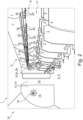
- a cabin 1 of an aircraft for civil aviation is shown obliquely from above.
- the cabin 1 is designed as a passenger cabin. It has a seating area 2 with a plurality of seats 3, which are arranged in rows of seats, e.g. three seats. Passengers 4 of the aircraft can sit on the seats 3.
- the cabin 1 can comprise one, two or more seating areas 2. Between the seating areas 2 or next to the seating area(s) 2 runs an aisle 5, along which the passengers can walk to get to their seats 3 or from there to a lounge and/or functional area 13 (see Figure 2 ) of cabin 1.
- An overhead area 6 with overhead luggage compartments 7 is arranged above the seating area 2.
- a supply channel 8 or passenger supply channel extends across the rows of seats.
- the supply channel 8 contains, for example, ventilation nozzles and seat belt signs for each row of seats or for each seat 3 in the row of seats.
- the cabin 1 comprises a mobile computer 9, e.g. a tablet or laptop.
- the computer 9 has a display.
- the computer can also be designed as a stationary computer with a screen.
- a member of the on-board personnel 20 who is in the cabin 1 uses the computer 9 and/or operates it.
- the cabin 1 has a monitoring arrangement 10 for monitoring monitoring areas 11, 14, 17 of the cabin 1.
- a schematic structure of the monitoring arrangement 10 is shown in the Figure 3 shown.
- the cabin 1 has a first monitoring area 11.
- the first monitoring area 11 is formed by the aisle 5 and/or it includes it.
- the monitoring arrangement 10 has a first sensor device 12.
- the first sensor device 12 comprises one or more first sensors, which are arranged on the wall, ceiling and/or floor in the cabin 1 and can form a sensor network.
- the first sensor or sensors are designed, for example, as optical sensors, e.g. as cameras, optionally as so-called time-of-flight sensors.
- the first sensor device 12 detects a position and/or presence of at least one person, in particular at least one passenger 4 or member of a crew or on-board personnel 20, in the first monitoring area 11 as first sensor data 21. In particular, the first sensor device 12 detects whether and/or how many people are in the aisle 5, whether and/or how many people enter the aisle 5 and whether and/or how many people leave the aisle 5.
- the cabin 1 is shown in a view of the backs of the seats 3 along the aisle 5.
- the cabin 1 has the lounge and/or functional area 13.
- the lounge and/or functional area 13 comprises a washroom 15 spatially separated from the seating area 2 and a waiting area 19 in front of the washroom 15.
- the lounge and/or functional area 13 can optionally additionally comprise an entrance and/or exit area of an aircraft door (not shown).
- the cabin 1 has a second monitoring area 14.
- the second monitoring area 14 is formed by the lounge and/or functional area 13 and/or it includes it.
- the monitoring arrangement 10 has a second sensor device 16.
- the second sensor device 16 comprises one or more second sensors, which can form a sensor network.
- the second sensor or sensors are designed, for example, as optical sensors, e.g. as cameras, optionally as so-called time-of-flight sensors.
- the second sensor or sensors are arranged on the wall, ceiling or floor in the washroom 15.
- One or more other second sensors can optionally be arranged on the wall, ceiling or floor in the waiting area 19 and/or in the entrance and/or exit area of the aircraft door.
- One or more second sensors can also be arranged on an access door to the washroom 15. These can be designed, for example, as motion sensors and detect a door opening and closing movement in order to be able to evaluate whether the washroom 15 is occupied or not.
- the second sensor or sensors arranged on the access door can also be designed as optical sensors.
- the second sensor device 16 detects a position and/or presence of at least one person in the second monitoring area 14 as second sensor data 22.
- the second sensor device 16 thus detects whether and/or how many people are in the residence and/or functional area 13, whether and/or how many people enter the residence and/or functional area 13 and whether and/or how many people leave it.
- the cabin 1 has at least one further monitoring area, in particular a third monitoring area 17.
- the third monitoring area 17 is formed by the seating area 2 or by the seating areas 2.
- the monitoring arrangement 10 has at least one further sensor device, in particular a third sensor device 18.
- the third sensor device 18 comprises a plurality of third sensors which form a sensor network.
- the third sensor or sensors are designed, for example, as optical sensors, e.g. as cameras, optionally as so-called time-of-flight sensors.
- the third sensors are arranged in the supply channel 8.
- Each seat 3 of the seating area 2, alternatively each row of seats, is assigned a third sensor.
- the third sensor device 18, in particular the third sensor assigned to the respective seat 3, detects whether the seat 3 is occupied by a person as third sensor data 23.
- the monitoring device 10 has an evaluation device 24 for evaluating the first, second and third sensor data 21, 22, 23.
- the evaluation device 24 is designed as a microcontroller. It is integrated in the computer 9. Alternatively, it can be a separate component which is and/or can be connected to the computer 9, e.g. via radio or a cable.
- the evaluation device 24 calculates a distance between people who are in the first and second monitoring areas 11, 14 and optionally in the third monitoring area 17 on the basis of the first and second sensor data 21, 22 and optionally additionally on the basis of the third sensor data 21, 22.
- the evaluation device 24 also evaluates the seat occupancy of the seats 3, in particular it evaluates whether and on which seats 3 of the seating area 2 a person is sitting and whether and which seat(s) are unoccupied.
- the computer 9 is connected to an external device, e.g. another computer outside the aircraft, which is used by ground staff at an airport, for signal and/or data purposes.
- the evaluated seat occupancy and optionally the calculated distance between the people in the Monitoring areas 11, 14, 17 can be transmitted to the other computer.
- This enables the ground staff, for example during a boarding process, to gain an impression of how quickly the passengers in the cabin 1 sit down on their seats 3, which seats 3 are already occupied, how many people are standing at what distance in the aisle 5, waiting area 19 and/or in the entrance and/or exit area of the aircraft door.
- This enables the ground staff to organize the boarding process in a more regulated manner, in particular by avoiding a passenger jam in the monitoring areas and/or by avoiding queues in front of the aircraft door.
- the monitoring device 10 comprises a plurality of output devices 25.
- the output devices 25 are arranged above each row of seats in the seating area 2 in the supply channel 8.
- Each of the output devices 25 is assigned to exactly one seat 3 in the row of seats.
- the output devices 25 are designed as traffic lights for outputting two or more optical signals of different colors.
- a first signal color output by the traffic light e.g. green
- a second signal color output by the traffic light e.g. red
- a prohibition signal 27 forms a prohibition signal 27.
- a third signal color e.g. orange
- the output devices 25 can be designed to output acoustic signals, which can indicate the output and the change between the optical signals.
- the release signal 26 and the prohibition signal 27 are intended to influence the position and/or presence of at least one person in the monitoring areas 11, 14, 17.
- the prohibition signal 27 signals to the passenger on the corresponding seat 3 that he must remain seated and is not allowed to leave the seat 3.
- the release signal 26 signals to the passenger on the corresponding seat 3 that he is allowed to stand up and leave the seat 3.
- the monitoring arrangement 10 comprises a control device 28 for controlling the output devices 25 based on the calculated distance between the people in the monitoring areas 11, 14, 17.
- the control device 28 is integrated in the computer 9 or can be connected to it.
- a control algorithm is stored in the control device 28, by means of which the output devices 25 can be controlled based on the calculated distance with algorithm-based control signals 29.
- the control algorithm includes limit values for a minimum distance between two people in one, several or all monitoring areas 11, 14, 17. If the limit value is reached or undershot, the control device 28 triggers the output of the prohibition signal 27 for the corresponding seats 3. If the limit value is not reached, the control device triggers the release signal 26 for the corresponding seats 3. According to the control algorithm, the control device 28 can also take into account, for example, the distance between two people and certain seats 3 and/or rows of seats, so that the control device can accordingly trigger the release signal 26 at certain rows of seats and the prohibition signal 27 at other rows of seats.
- the member of the on-board crew 20 can control the output devices 25 by means of the computer 9 and in particular by means of the control device 28 integrated therein or connected to it, also by issuing manual control commands.
- the calculated distance and/or the evaluated seat occupancy can be shown on the display so that the member of the on-board crew 20 can take note of it.
- the control commands can be entered via the display as a touchscreen or via a keyboard, etc.
- the member of the on-board crew 20 can influence the process of passengers 4 disembarking from the aircraft by manually controlling the output devices 25. If the release signal 26 is activated, for example, only for the seats 3 of every third row of seats in the seating area 2, it can be achieved in particular that not all passengers 4 rush into the aisle 5 at the same time to take their luggage from the overhead storage compartments 7 and move to the aircraft door. The disembarkation process can take place in an orderly manner and is thus more relaxed and pleasant for the passengers 4 and the on-board crew 20. In addition, close gatherings can be avoided and any necessary distance rules in the first and second monitoring areas 11, 14 can be observed.
- the evaluation device 24 is connected to the first, second and third sensor devices 12,16,18 by signal technology. Sensor devices 12, 16, 18 transmit the recorded first, second and third sensor data 21, 22, 23 to the evaluation device 24.
- the evaluation device 24 is connected to the control device 28 in terms of signaling. It transmits the calculated distance as distance signals 31 to the control device 28. It can also transmit the calculated distance as distance signals for display on the display of the computer 9. The evaluation device 24 also transmits the evaluated seat occupancy as seat occupancy signals 32 to the control device 28 and/or for display on the display of the computer 9.
- the control device 28 is connected to the output devices 25 via radio, in particular WiFi or Bluetooth. For control, the control device 28 sends the algorithm-based control signals 29 or control signals 30 based on the manual control commands to the output devices 24.
Landscapes
- Engineering & Computer Science (AREA)
- Aviation & Aerospace Engineering (AREA)
- Geophysics And Detection Of Objects (AREA)
- Alarm Systems (AREA)
- Traffic Control Systems (AREA)
- Radar Systems Or Details Thereof (AREA)
Claims (8)
- Cabine (1) destinée à un avion, comprenantune première zone de surveillance (11),une deuxième zone de surveillance (14),un agencement de surveillance (10) pour surveiller la première zone de surveillance (11) et la deuxième zone de surveillance (14),dans laquelle l'agencement de surveillance (10) comprend au moins un dispositif de sortie (25),dans laquelle ledit au moins un dispositif de sortie (25) est réalisé et/ou agencé pour émettre un signal d'autorisation (26) et un signal d'interdiction (27) concernant un changement d'une position et/ou la présence d'au moins une personne dans la première zone de surveillance (11) et/ou dans la deuxième zone de surveillance (14),dans laquelle la cabine (1) comprend une zone de sièges (2) avec plusieurs sièges (3), l'agencement de surveillance (10) comprenant plusieurs dispositifs de sortie (25), un dispositif de sortie (25) étant attribué à chaque siège (3) de la zone de sièges (2),dans laquelle le signal d'interdiction (27) signale au passager sur le siège (3) correspondant qu'il doit rester assis et ne doit pas quitter le siège (3), le signal d'autorisation (26) signalant au passager sur le siège (3) correspondant qu'il peut se lever et peut quitter le siège (3),dans laquelle la première zone de surveillance (11) est au moins un couloir (5) à côté ou entre les sièges (3) de la zone de sièges (2) et la deuxième zone de surveillance (14) comprend au moins une zone de séjour et/ou fonctionnelle (13) de la cabine (1),dans laquelle la cabine (1) présente au moins une zone de surveillance supplémentaire (17), ladite au moins une zone de surveillance supplémentaire (17) comprenant la zone de sièges (2),dans laquelle l'agencement de surveillance (10) comprend un premier dispositif capteur (12) et un deuxième dispositif capteur (16), dans laquelle le premier dispositif capteur (12) est réalisé et/ou disposé pour détecter la présence et/ou la position d'au moins une personne dans la première zone de surveillance (11) en tant que premières données de capteur (21), et dans laquelle le deuxième dispositif capteur (16) est réalisé pour détecter la présence et/ou la position d'au moins une personne dans la deuxième zone de surveillance (14) en tant que deuxièmes données de capteur (22), et dans laquelle l'agencement de surveillance (10) comprend au moins un dispositif capteur supplémentaire (18), dans laquelle ledit au moins un dispositif capteur supplémentaire (18) est réalisé pour détecter une position et/ou la présence d'au moins une personne dans ladite au moins une zone de surveillance supplémentaire (17) en tant que données de capteur supplémentaires (23),dans laquelle l'agencement de surveillance (10) comprend un dispositif d'évaluation (24),dans laquelle le dispositif d'évaluation (24) est réalisé pour calculer une distance entre au moins une personne dans l'une des zones de surveillance (11, 14, 17) et au moins une autre personne dans une autre des zones de surveillance (11, 14, 17) sur la base des premières données de capteur (21), des deuxièmes données de capteur (22) et/ou des données de capteur supplémentaires (23),dans laquelle l'agencement de surveillance (10) comprend un dispositif de commande (28), le dispositif de commande (28) pouvant être relié et/ou étant relié au dispositif d'évaluation (26) en termes de signal, le dispositif de commande (28) étant réalisé pour piloter ledit au moins un dispositif de sortie (25) afin d'émettre le signal d'autorisation (26) ou le signal d'interdiction (27) en fonction de la distance calculée,dans laquelle un algorithme de commande est mémorisé dans le dispositif de commande (28), au moyen duquel les dispositifs de sortie (25) peuvent être pilotés sur la base de la distance calculée avec des signaux de commande (29) à base d'algorithme, dans laquelle l'algorithme de commande comprend des valeurs limites pour une distance minimale entre respectivement deux personnes dans une, plusieurs ou toutes les zones de surveillance (11, 14, 17) et est réalisé comme suit :- si la valeur limite est atteinte ou soupassée, alors le dispositif de commande (28) pilote la sortie du signal d'interdiction (27) pour les sièges (3) correspondants,- si la valeur limite n'est pas atteinte, alors le dispositif de commande (28) pilote le signal d'autorisation (26) pour les sièges (3) correspondants.
- Cabine (1) selon la revendication 1, caractérisée en ce que le signal d'autorisation (26) et/ou le signal d'interdiction (27) sont des signaux optiques.
- Cabine (1) selon la revendication 1 ou 2, caractérisée en ce que ledit au moins un dispositif de sortie (25) est un feu de signalisation qui est réalisé pour afficher une première couleur de signalisation en tant que signal d'autorisation (26) et une deuxième couleur de signalisation en tant que signal d'interdiction (27).
- Cabine (1) selon l'une quelconque des revendications précédentes, caractérisée en ce que le dispositif d'évaluation (24) est réalisé pour évaluer une occupation de siège des sièges (3) sur la base des données de capteur supplémentaires (23).
- Cabine (1) selon la revendication 4, caractérisée en ce que la cabine (1) comprend un ordinateur (9), et le dispositif d'évaluation (24) est intégré dans l'ordinateur (9) de manière mobile ou installé à demeure et/ou est relié à celui-ci, dans laquelle l'ordinateur (9) présente un affichage ou un écran, dans laquelle l'occupation de siège évaluée et/ou la distance calculée peuvent être consultées et/ou affichées sur l'affichage ou à l'écran.
- Cabine (1) selon la revendication 5, caractérisée en ce que le dispositif d'évaluation (26) et/ou l'ordinateur (9) peuvent être reliés et/ou sont reliés à un appareil externe à l'extérieur de l'avion, dans laquelle le dispositif d'évaluation (26) et/ou l'ordinateur (9) sont réalisés pour transmettre l'occupation de siège et/ou la distance calculée à l'appareil externe.
- Avion comprenant la cabine (1) selon l'une quelconque des revendications 1 à 6.
- Procédé permettant de surveiller une cabine (1) selon l'une quelconque des revendications 1 à 6 d'un avion, dans lequel le signal d'autorisation (26) et/ou le signal d'interdiction (27) concernant un changement d'une position et/ou la présence d'au moins une personne dans une première zone de surveillance (11) de la cabine (1) et/ou dans une deuxième zone de surveillance (14) de la cabine (1) sont émis, dans lequel- si la valeur limite est atteinte ou soupassée, alors le dispositif de commande (28) pilote la sortie du signal d'interdiction (27) pour les sièges (3) correspondants,- si la valeur limite n'est pas atteinte, alors le dispositif de commande (28) pilote le signal d'autorisation (26) pour les sièges (3) correspondants.
Applications Claiming Priority (2)
| Application Number | Priority Date | Filing Date | Title |
|---|---|---|---|
| DE102020210572.3A DE102020210572A1 (de) | 2020-08-20 | 2020-08-20 | Kabine für ein Flugzeug mit einer Überwachungsanordnung, Flugzeug mit der Kabine, Überwachungsanordnung und Verfahren zur Überwachung einer Kabine eines Flugzeugs |
| PCT/EP2021/073042 WO2022038227A1 (fr) | 2020-08-20 | 2021-08-19 | Cabine destinée à un aéronef comprenant un dispositif de surveillance, aéronef comprenant la cabine, dispositif de surveillance et procédé de surveillance d'une cabine d'un aéronef |
Publications (2)
| Publication Number | Publication Date |
|---|---|
| EP4200211A1 EP4200211A1 (fr) | 2023-06-28 |
| EP4200211B1 true EP4200211B1 (fr) | 2024-12-04 |
Family
ID=77627123
Family Applications (1)
| Application Number | Title | Priority Date | Filing Date |
|---|---|---|---|
| EP21765639.6A Active EP4200211B1 (fr) | 2020-08-20 | 2021-08-19 | Cabine destinée à un aéronef comprenant un dispositif de surveillance, aéronef comprenant la cabine, dispositif de surveillance et procédé de surveillance d'une cabine d'un aéronef |
Country Status (6)
| Country | Link |
|---|---|
| US (1) | US12515811B2 (fr) |
| EP (1) | EP4200211B1 (fr) |
| BR (1) | BR112023001422A2 (fr) |
| CA (1) | CA3190608A1 (fr) |
| DE (1) | DE102020210572A1 (fr) |
| WO (1) | WO2022038227A1 (fr) |
Families Citing this family (2)
| Publication number | Priority date | Publication date | Assignee | Title |
|---|---|---|---|---|
| DE102020210572A1 (de) * | 2020-08-20 | 2022-02-24 | Diehl Aerospace Gmbh | Kabine für ein Flugzeug mit einer Überwachungsanordnung, Flugzeug mit der Kabine, Überwachungsanordnung und Verfahren zur Überwachung einer Kabine eines Flugzeugs |
| US20250108925A1 (en) * | 2023-10-02 | 2025-04-03 | Hamilton Sundstrand Corporation | Cabin occupancy sensor for aircraft ecs |
Family Cites Families (27)
| Publication number | Priority date | Publication date | Assignee | Title |
|---|---|---|---|---|
| DE102006042299B4 (de) | 2006-09-08 | 2011-04-28 | Airbus Operations Gmbh | Bedingtes Warn- und Meldesystem für eine Flugzeugkabine zur Feststellung des Kabinenstatus |
| US20120010910A1 (en) * | 2010-07-08 | 2012-01-12 | Lele Avinash S | Systems and methods for optimizing the scheduling of resources on an airplane |
| US20120010912A1 (en) * | 2010-07-08 | 2012-01-12 | Lele Avinash S | Systems and methods for optimizing the scheduling of resources on an airplane |
| ITBO20120299A1 (it) * | 2012-05-31 | 2013-12-01 | Filippo Guerzoni | Dispositivo, sistema e metodo di sorveglianza di un prestabilito volume. |
| EP2738060A1 (fr) | 2012-11-29 | 2014-06-04 | Bombardier Transportation GmbH | Système de guidage de passagers pour guider les passagers dans un véhicule de transport public |
| US8806543B1 (en) * | 2013-03-05 | 2014-08-12 | The Boeing Company | In-flight passenger information system |
| US9302781B2 (en) * | 2014-02-25 | 2016-04-05 | Astronics Advanced Electronic Systems Corp. | Apparatus and method to monitor the occupancy of seating |
| FR3026216B1 (fr) * | 2014-09-18 | 2016-12-23 | Dassault Aviat | Systeme d'assistance au pilotage d'une plate-forme, et procede associe |
| FR3027718B1 (fr) * | 2014-10-28 | 2019-06-21 | Latecoere | Procede et systeme de surveillance et de securisation d'une enceinte de vehicule, notamment d'un avion |
| US11037074B2 (en) * | 2015-03-09 | 2021-06-15 | The Boeing Company | Digital seat ordering and management |
| US11391810B2 (en) * | 2016-08-31 | 2022-07-19 | Ford Global Technologies, Llc | Method and apparatus for vehicle occupant location detection |
| US10252688B2 (en) * | 2017-03-22 | 2019-04-09 | Ford Global Technologies, Llc | Monitoring a vehicle cabin |
| FR3065104B1 (fr) | 2017-04-07 | 2023-01-20 | Zodiac Aerospace | Systeme de suivi a distance d'une zone destinee a accueillir au moins un passager d'un avion et cabine d'avion equipee d'un tel systeme de suivi a distance. |
| US20190177004A1 (en) * | 2017-12-08 | 2019-06-13 | Rockwell Collins, Inc. | Integrated Imaging System for a Connected Aircraft |
| US11689886B2 (en) * | 2018-11-27 | 2023-06-27 | Gogo Business Aviation Llc | Passenger location platform |
| US11505320B2 (en) * | 2019-07-01 | 2022-11-22 | The Boeing Company | Deployable handle system for a vehicle |
| US11203433B2 (en) * | 2019-07-30 | 2021-12-21 | B/E Aerospace, Inc. | Predictive aircraft passenger cabin service system and method |
| US10803848B1 (en) * | 2019-11-22 | 2020-10-13 | The Boeing Company | Audio instrument with three-dimensional localization |
| US20210322589A1 (en) * | 2020-04-17 | 2021-10-21 | Dennis Lynn Matter | Method for using Human-safe UVC to Control Contagion Presence within the Aircraft Cabin |
| DE202020102795U1 (de) * | 2020-05-07 | 2020-07-20 | Spleenlab GmbH | Zur räumlichen Distanzierung ("Social Distancing") geeignete Personenerfassung und Distanzmessung |
| US20210391089A1 (en) * | 2020-06-15 | 2021-12-16 | Honeywell International Inc. | Methods and systems for reducing a risk of spread of an illness in a building |
| US11783658B2 (en) * | 2020-06-15 | 2023-10-10 | Honeywell International Inc. | Methods and systems for maintaining a healthy building |
| US11625964B2 (en) * | 2020-06-15 | 2023-04-11 | Honeywell International Inc. | Methods and systems for temperature screening using a mobile device |
| US12299760B2 (en) * | 2020-06-16 | 2025-05-13 | Life In The Air, Inc. | Distributed service-and-transaction system |
| DE102020210572A1 (de) * | 2020-08-20 | 2022-02-24 | Diehl Aerospace Gmbh | Kabine für ein Flugzeug mit einer Überwachungsanordnung, Flugzeug mit der Kabine, Überwachungsanordnung und Verfahren zur Überwachung einer Kabine eines Flugzeugs |
| US20220198906A1 (en) * | 2020-12-23 | 2022-06-23 | Jean Ava Pollard | Social Distancing System |
| JP7524919B2 (ja) * | 2022-03-03 | 2024-07-30 | トヨタ自動車株式会社 | 車載センサ洗浄システム、方法、及びプログラム |
-
2020
- 2020-08-20 DE DE102020210572.3A patent/DE102020210572A1/de not_active Withdrawn
-
2021
- 2021-08-19 WO PCT/EP2021/073042 patent/WO2022038227A1/fr not_active Ceased
- 2021-08-19 BR BR112023001422A patent/BR112023001422A2/pt unknown
- 2021-08-19 CA CA3190608A patent/CA3190608A1/fr active Pending
- 2021-08-19 EP EP21765639.6A patent/EP4200211B1/fr active Active
- 2021-08-19 US US18/021,491 patent/US12515811B2/en active Active
Also Published As
| Publication number | Publication date |
|---|---|
| EP4200211A1 (fr) | 2023-06-28 |
| CA3190608A1 (fr) | 2022-02-24 |
| DE102020210572A1 (de) | 2022-02-24 |
| WO2022038227A1 (fr) | 2022-02-24 |
| BR112023001422A2 (pt) | 2023-03-07 |
| US12515811B2 (en) | 2026-01-06 |
| US20240017848A1 (en) | 2024-01-18 |
Similar Documents
| Publication | Publication Date | Title |
|---|---|---|
| DE102006042299B4 (de) | Bedingtes Warn- und Meldesystem für eine Flugzeugkabine zur Feststellung des Kabinenstatus | |
| EP2563660B1 (fr) | Structure de support à utiliser dans un système d'amenée d'air, système d'alimentation pourvu d'une telle structure de support, et procédé de configuration associé | |
| DE102014209554A1 (de) | Leitung von Fahrgästen | |
| DE102016012912B4 (de) | Überwachungsmodul für einen Sitzplatz eines Passagierflugzeuges, Überwachungseinrichtung und Passagierflugzeug | |
| DE102013008289A1 (de) | Flugzeugbereich | |
| EP3473521A1 (fr) | Véhicule pour transport de passagers | |
| DE102009007491A1 (de) | Bodenelement mit Beleuchtung | |
| DE102015218588A1 (de) | Bordeigenes Warnsystem | |
| DE102010033624A1 (de) | Sitzplatzbelegungserkennungssystem für ein Kraftfahrzeug | |
| EP1059230A2 (fr) | Unité fonctionelle pour cabines de passagers, en particulier pour cabines de passagers d'avions | |
| WO2022038227A1 (fr) | Cabine destinée à un aéronef comprenant un dispositif de surveillance, aéronef comprenant la cabine, dispositif de surveillance et procédé de surveillance d'une cabine d'un aéronef | |
| DE102015219692A1 (de) | Verfahren zum Bereitstellen von Reiseinformationen und Informationssystem | |
| DE102011086454A1 (de) | Überwachungsvorrichtung sowie Verfahren zum Überwachen eines Bewegungsprofils eines Anwenders im Bereich eines Betätigungselementes eines Luft- oder Raumfahrzeuges | |
| DE102013008290A1 (de) | Multifunktionales Flugzeugmonument und Flugzeugbereich | |
| WO2013149877A1 (fr) | Système d'éclairage, moyen de transport en commun et procédé permettant de faire fonctionner un système d'éclairage | |
| EP1295791A2 (fr) | Système de sécurité d'un aéronef pour empêcher l'utilisation frauduleuse du pilotage manuel | |
| DE10304073B4 (de) | Informationssystem zur dynamischen Wegeleitung | |
| DE102021001388A1 (de) | Fahrgastleitsystem und Verfahren zum Leiten von Fahrgästen | |
| EP4179456A1 (fr) | Système pour surveiller le fonctionnement d'un navire | |
| DE2210312A1 (de) | Anordnung in einem verkehrsflugzeug zum herabsetzen der entfuehrungsgefahr | |
| DE102019003553B4 (de) | Ansageeinrichtung, Passagierflugzeug, Verfahren zur Ausgabe einer Ansage in einem Passagierflugzeug und Verwendung eines CMS | |
| DE10225023A1 (de) | Verfahren zur Überwachung in einem Personenbeförderungsmittel | |
| DE102015202304A1 (de) | Verfahren zum Betreiben eines Fahrzeugs und Fahrzeug | |
| DE102019134864A1 (de) | System und Verfahren zum Steuern einer Warteschlange zum Eintreten in ein Verkehrsmittel | |
| EP4173968A1 (fr) | Procédés et systèmes de débarquement contrôlé de passagers d'aéronef |
Legal Events
| Date | Code | Title | Description |
|---|---|---|---|
| STAA | Information on the status of an ep patent application or granted ep patent |
Free format text: STATUS: UNKNOWN |
|
| STAA | Information on the status of an ep patent application or granted ep patent |
Free format text: STATUS: THE INTERNATIONAL PUBLICATION HAS BEEN MADE |
|
| PUAI | Public reference made under article 153(3) epc to a published international application that has entered the european phase |
Free format text: ORIGINAL CODE: 0009012 |
|
| STAA | Information on the status of an ep patent application or granted ep patent |
Free format text: STATUS: REQUEST FOR EXAMINATION WAS MADE |
|
| 17P | Request for examination filed |
Effective date: 20230123 |
|
| AK | Designated contracting states |
Kind code of ref document: A1 Designated state(s): AL AT BE BG CH CY CZ DE DK EE ES FI FR GB GR HR HU IE IS IT LI LT LU LV MC MK MT NL NO PL PT RO RS SE SI SK SM TR |
|
| DAV | Request for validation of the european patent (deleted) | ||
| DAX | Request for extension of the european patent (deleted) | ||
| GRAP | Despatch of communication of intention to grant a patent |
Free format text: ORIGINAL CODE: EPIDOSNIGR1 |
|
| STAA | Information on the status of an ep patent application or granted ep patent |
Free format text: STATUS: GRANT OF PATENT IS INTENDED |
|
| INTG | Intention to grant announced |
Effective date: 20240905 |
|
| GRAS | Grant fee paid |
Free format text: ORIGINAL CODE: EPIDOSNIGR3 |
|
| GRAA | (expected) grant |
Free format text: ORIGINAL CODE: 0009210 |
|
| STAA | Information on the status of an ep patent application or granted ep patent |
Free format text: STATUS: THE PATENT HAS BEEN GRANTED |
|
| AK | Designated contracting states |
Kind code of ref document: B1 Designated state(s): AL AT BE BG CH CY CZ DE DK EE ES FI FR GB GR HR HU IE IS IT LI LT LU LV MC MK MT NL NO PL PT RO RS SE SI SK SM TR |
|
| REG | Reference to a national code |
Ref country code: CH Ref legal event code: EP |
|
| REG | Reference to a national code |
Ref country code: DE Ref legal event code: R096 Ref document number: 502021006017 Country of ref document: DE |
|
| REG | Reference to a national code |
Ref country code: IE Ref legal event code: FG4D Free format text: LANGUAGE OF EP DOCUMENT: GERMAN |
|
| REG | Reference to a national code |
Ref country code: LT Ref legal event code: MG9D |
|
| REG | Reference to a national code |
Ref country code: NL Ref legal event code: MP Effective date: 20241204 |
|
| PG25 | Lapsed in a contracting state [announced via postgrant information from national office to epo] |
Ref country code: HR Free format text: LAPSE BECAUSE OF FAILURE TO SUBMIT A TRANSLATION OF THE DESCRIPTION OR TO PAY THE FEE WITHIN THE PRESCRIBED TIME-LIMIT Effective date: 20241204 |
|
| PG25 | Lapsed in a contracting state [announced via postgrant information from national office to epo] |
Ref country code: FI Free format text: LAPSE BECAUSE OF FAILURE TO SUBMIT A TRANSLATION OF THE DESCRIPTION OR TO PAY THE FEE WITHIN THE PRESCRIBED TIME-LIMIT Effective date: 20241204 |
|
| PG25 | Lapsed in a contracting state [announced via postgrant information from national office to epo] |
Ref country code: BG Free format text: LAPSE BECAUSE OF FAILURE TO SUBMIT A TRANSLATION OF THE DESCRIPTION OR TO PAY THE FEE WITHIN THE PRESCRIBED TIME-LIMIT Effective date: 20241204 |
|
| PG25 | Lapsed in a contracting state [announced via postgrant information from national office to epo] |
Ref country code: ES Free format text: LAPSE BECAUSE OF FAILURE TO SUBMIT A TRANSLATION OF THE DESCRIPTION OR TO PAY THE FEE WITHIN THE PRESCRIBED TIME-LIMIT Effective date: 20241204 |
|
| PG25 | Lapsed in a contracting state [announced via postgrant information from national office to epo] |
Ref country code: NO Free format text: LAPSE BECAUSE OF FAILURE TO SUBMIT A TRANSLATION OF THE DESCRIPTION OR TO PAY THE FEE WITHIN THE PRESCRIBED TIME-LIMIT Effective date: 20250304 |
|
| PG25 | Lapsed in a contracting state [announced via postgrant information from national office to epo] |
Ref country code: LV Free format text: LAPSE BECAUSE OF FAILURE TO SUBMIT A TRANSLATION OF THE DESCRIPTION OR TO PAY THE FEE WITHIN THE PRESCRIBED TIME-LIMIT Effective date: 20241204 Ref country code: GR Free format text: LAPSE BECAUSE OF FAILURE TO SUBMIT A TRANSLATION OF THE DESCRIPTION OR TO PAY THE FEE WITHIN THE PRESCRIBED TIME-LIMIT Effective date: 20250305 |
|
| PG25 | Lapsed in a contracting state [announced via postgrant information from national office to epo] |
Ref country code: RS Free format text: LAPSE BECAUSE OF FAILURE TO SUBMIT A TRANSLATION OF THE DESCRIPTION OR TO PAY THE FEE WITHIN THE PRESCRIBED TIME-LIMIT Effective date: 20250304 |
|
| PG25 | Lapsed in a contracting state [announced via postgrant information from national office to epo] |
Ref country code: NL Free format text: LAPSE BECAUSE OF FAILURE TO SUBMIT A TRANSLATION OF THE DESCRIPTION OR TO PAY THE FEE WITHIN THE PRESCRIBED TIME-LIMIT Effective date: 20241204 |
|
| PG25 | Lapsed in a contracting state [announced via postgrant information from national office to epo] |
Ref country code: SM Free format text: LAPSE BECAUSE OF FAILURE TO SUBMIT A TRANSLATION OF THE DESCRIPTION OR TO PAY THE FEE WITHIN THE PRESCRIBED TIME-LIMIT Effective date: 20241204 |
|
| PG25 | Lapsed in a contracting state [announced via postgrant information from national office to epo] |
Ref country code: PL Free format text: LAPSE BECAUSE OF FAILURE TO SUBMIT A TRANSLATION OF THE DESCRIPTION OR TO PAY THE FEE WITHIN THE PRESCRIBED TIME-LIMIT Effective date: 20241204 |
|
| PG25 | Lapsed in a contracting state [announced via postgrant information from national office to epo] |
Ref country code: IS Free format text: LAPSE BECAUSE OF FAILURE TO SUBMIT A TRANSLATION OF THE DESCRIPTION OR TO PAY THE FEE WITHIN THE PRESCRIBED TIME-LIMIT Effective date: 20250404 |
|
| PG25 | Lapsed in a contracting state [announced via postgrant information from national office to epo] |
Ref country code: PT Free format text: LAPSE BECAUSE OF FAILURE TO SUBMIT A TRANSLATION OF THE DESCRIPTION OR TO PAY THE FEE WITHIN THE PRESCRIBED TIME-LIMIT Effective date: 20250404 |
|
| PG25 | Lapsed in a contracting state [announced via postgrant information from national office to epo] |
Ref country code: EE Free format text: LAPSE BECAUSE OF FAILURE TO SUBMIT A TRANSLATION OF THE DESCRIPTION OR TO PAY THE FEE WITHIN THE PRESCRIBED TIME-LIMIT Effective date: 20241204 |
|
| PG25 | Lapsed in a contracting state [announced via postgrant information from national office to epo] |
Ref country code: RO Free format text: LAPSE BECAUSE OF FAILURE TO SUBMIT A TRANSLATION OF THE DESCRIPTION OR TO PAY THE FEE WITHIN THE PRESCRIBED TIME-LIMIT Effective date: 20241204 |
|
| PG25 | Lapsed in a contracting state [announced via postgrant information from national office to epo] |
Ref country code: SK Free format text: LAPSE BECAUSE OF FAILURE TO SUBMIT A TRANSLATION OF THE DESCRIPTION OR TO PAY THE FEE WITHIN THE PRESCRIBED TIME-LIMIT Effective date: 20241204 |
|
| PG25 | Lapsed in a contracting state [announced via postgrant information from national office to epo] |
Ref country code: CZ Free format text: LAPSE BECAUSE OF FAILURE TO SUBMIT A TRANSLATION OF THE DESCRIPTION OR TO PAY THE FEE WITHIN THE PRESCRIBED TIME-LIMIT Effective date: 20241204 |
|
| PG25 | Lapsed in a contracting state [announced via postgrant information from national office to epo] |
Ref country code: IT Free format text: LAPSE BECAUSE OF FAILURE TO SUBMIT A TRANSLATION OF THE DESCRIPTION OR TO PAY THE FEE WITHIN THE PRESCRIBED TIME-LIMIT Effective date: 20241204 |
|
| REG | Reference to a national code |
Ref country code: DE Ref legal event code: R097 Ref document number: 502021006017 Country of ref document: DE |
|
| PG25 | Lapsed in a contracting state [announced via postgrant information from national office to epo] |
Ref country code: SE Free format text: LAPSE BECAUSE OF FAILURE TO SUBMIT A TRANSLATION OF THE DESCRIPTION OR TO PAY THE FEE WITHIN THE PRESCRIBED TIME-LIMIT Effective date: 20241204 |
|
| PG25 | Lapsed in a contracting state [announced via postgrant information from national office to epo] |
Ref country code: DK Free format text: LAPSE BECAUSE OF FAILURE TO SUBMIT A TRANSLATION OF THE DESCRIPTION OR TO PAY THE FEE WITHIN THE PRESCRIBED TIME-LIMIT Effective date: 20241204 |
|
| PLBE | No opposition filed within time limit |
Free format text: ORIGINAL CODE: 0009261 |
|
| STAA | Information on the status of an ep patent application or granted ep patent |
Free format text: STATUS: NO OPPOSITION FILED WITHIN TIME LIMIT |
|
| REG | Reference to a national code |
Ref country code: CH Ref legal event code: L10 Free format text: ST27 STATUS EVENT CODE: U-0-0-L10-L00 (AS PROVIDED BY THE NATIONAL OFFICE) Effective date: 20251015 |
|
| PGFP | Annual fee paid to national office [announced via postgrant information from national office to epo] |
Ref country code: FR Payment date: 20250828 Year of fee payment: 5 Ref country code: AT Payment date: 20251020 Year of fee payment: 5 |
|
| 26N | No opposition filed |
Effective date: 20250905 |
|
| PGFP | Annual fee paid to national office [announced via postgrant information from national office to epo] |
Ref country code: DE Payment date: 20251020 Year of fee payment: 5 |
|
| REG | Reference to a national code |
Ref country code: CH Ref legal event code: H13 Free format text: ST27 STATUS EVENT CODE: U-0-0-H10-H13 (AS PROVIDED BY THE NATIONAL OFFICE) Effective date: 20260324 |
|
| PG25 | Lapsed in a contracting state [announced via postgrant information from national office to epo] |
Ref country code: MC Free format text: LAPSE BECAUSE OF FAILURE TO SUBMIT A TRANSLATION OF THE DESCRIPTION OR TO PAY THE FEE WITHIN THE PRESCRIBED TIME-LIMIT Effective date: 20241204 |
|
| PG25 | Lapsed in a contracting state [announced via postgrant information from national office to epo] |
Ref country code: LU Free format text: LAPSE BECAUSE OF NON-PAYMENT OF DUE FEES Effective date: 20250819 |
|
| PG25 | Lapsed in a contracting state [announced via postgrant information from national office to epo] |
Ref country code: CH Free format text: LAPSE BECAUSE OF NON-PAYMENT OF DUE FEES Effective date: 20250831 |
|
| GBPC | Gb: european patent ceased through non-payment of renewal fee |
Effective date: 20250819 |