EP4198641B1 - Natürliche hemmung für uhrwerk und uhrwerk, das eine solche uhrhemmung umfasst - Google Patents
Natürliche hemmung für uhrwerk und uhrwerk, das eine solche uhrhemmung umfasst Download PDFInfo
- Publication number
- EP4198641B1 EP4198641B1 EP21215870.3A EP21215870A EP4198641B1 EP 4198641 B1 EP4198641 B1 EP 4198641B1 EP 21215870 A EP21215870 A EP 21215870A EP 4198641 B1 EP4198641 B1 EP 4198641B1
- Authority
- EP
- European Patent Office
- Prior art keywords
- escapement
- anchor
- escape wheel
- natural
- balance
- Prior art date
- Legal status (The legal status is an assumption and is not a legal conclusion. Google has not performed a legal analysis and makes no representation as to the accuracy of the status listed.)
- Active
Links
Images


Classifications
-
- G—PHYSICS
- G04—HOROLOGY
- G04B—MECHANICALLY-DRIVEN CLOCKS OR WATCHES; MECHANICAL PARTS OF CLOCKS OR WATCHES IN GENERAL; TIME PIECES USING THE POSITION OF THE SUN, MOON OR STARS
- G04B15/00—Escapements
- G04B15/06—Free escapements
- G04B15/08—Lever escapements
-
- G—PHYSICS
- G04—HOROLOGY
- G04B—MECHANICALLY-DRIVEN CLOCKS OR WATCHES; MECHANICAL PARTS OF CLOCKS OR WATCHES IN GENERAL; TIME PIECES USING THE POSITION OF THE SUN, MOON OR STARS
- G04B15/00—Escapements
-
- G—PHYSICS
- G04—HOROLOGY
- G04B—MECHANICALLY-DRIVEN CLOCKS OR WATCHES; MECHANICAL PARTS OF CLOCKS OR WATCHES IN GENERAL; TIME PIECES USING THE POSITION OF THE SUN, MOON OR STARS
- G04B15/00—Escapements
- G04B15/14—Component parts or constructional details, e.g. construction of the lever or the escape wheel
Definitions
- the present invention relates to a natural escapement for a clock movement, also known as a tangential impulse escapement.
- the present invention relates more particularly to a natural escapement protected against damage that may be caused by premature triggering of the escapement impulse in the absence of the balance.
- the present invention also relates to a clock movement comprising such an escapement.
- Breguet's natural escapement The principle of the natural escapement was invented by Abraham Louis Breguet at the beginning of the 19th century.
- the advantage of Breguet's natural escapement is that it is a free escapement, since the balance wheel is only disturbed by the operation of the escapement for a small fraction of its oscillation.
- Breguet's natural escapement also has the advantage of giving each alternation a direct and tangential impulse to the balance wheel. In other words, the energy is transferred directly from the escapement wheel to the balance wheel, without passing through an anchor. Furthermore, the energy is transmitted only tangentially, so that the friction generated by the operation of this escapement is limited.
- a natural escapement does not have a lost stroke in its function of maintaining the oscillations of the balance wheel; it delivers a similar impulse at each alternation, in a symmetrical and more uniform manner, so that mechanical energy losses due to lost strokes are eliminated. All these qualities make the natural exhaust potentially one of the most efficient exhausts.
- the document CH 712 631 A1 discloses a natural escapement having an anchor with additional lifts. These lifts have the function of retaining stops acting on the escapement wheel.
- the present invention aims to overcome the above-mentioned and other problems by providing a natural escapement for a clockwork movement that is protected against the effects of triggering the escapement function when the balance wheel is not present.
- the present invention relates to a natural escapement for a watch movement performing a succession of operating cycles each composed of a first and a second alternation of a balance wheel during which the balance wheel moves from a first extreme position to a second extreme position passing through a middle rest position, then from its second extreme position to its first extreme position passing through its middle rest position a second time, this balance wheel comprising a balance wheel on an axis of which a balance wheel plate is adjusted, this natural escapement comprising a first escape wheel provided with at least a first toothing, this first escape wheel, arranged to be driven by a wheel of the clockwork movement, in turn driving a second escape wheel provided with at least a second toothing, the first and second escapement wheels forming a kinematic chain arranged to cooperate with an anchor capable of pivoting about an anchor stem, the balance wheel causing the anchor to pivot at each of the first and second vibrations, this anchor being arranged to block respectively the first and second escapement wheels temporarily during the second and first vibrations of an operating cycle, the
- the invention also relates to a clockwork movement comprising a natural escapement of the type described above.
- the present invention provides a natural escapement protected against damage that can be caused by premature triggering of the impulse.
- the first escapement wheel is advantageously ensured to rest when, in the absence of the balance wheel, this rest is not ensured by the cooperation between this balance wheel and the anchor.
- the second escapement wheel is not retained by the escapement function and can therefore rotate without control, which can cause a loss of the timekeeping function with an undesired advance, or even a sudden stop after acceleration of the gear train of the watch movement which may lead to deterioration of the components of the gear train and the escapement.
- the first and second safety levers are arranged so that, in the absence of the balance, the second escapement wheel, by acting on the second safety lever, causes the pivoting of the second arm of the anchor, the anchor and the first arm of the anchor to ensure the resting of the first escapement wheel on the part of this anchor which, in normal times, i.e. when the balance wheel plate is present, performs the function of a stop pallet to temporarily block the first escapement wheel during an operating cycle of the natural escapement.
- the first and second safety levers are designed so as not to be in contact with the first and second escapement wheels during normal operation of the escapement during which it is the balance wheel plate which causes the pivoting of the anchor.
- the present invention proceeds from the general inventive idea which consists in providing the first and second arms of the anchor of a natural escapement, also known by its name tangential impulse escapement, with a first and a second safety lever in order to guarantee that, if the watchmaker, for any reason, needs to remove the balance wheel, an unexpected triggering of the rotation of the first and second escapement wheels is immediately stopped by bringing one of the first and second escapement wheels into its rest position.
- a natural escapement also known by its name tangential impulse escapement
- the safety levers are arranged so that, when the balance wheel is removed, the second escapement wheel, by action on the second safety lever, pivots the anchor and the first arm of this anchor to allow the first escapement wheel to come to a stop in its rest position resting against the part of this anchor which, in normal times, that is to say when the balance wheel is present, performs the function of a stop pallet to temporarily block the first mobile exhaust during a natural exhaust operating cycle.
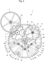
- the natural escapement is represented in its rest position at the figure 1 .
- This natural escapement 1 is arranged to be driven by a wheel of the clockwork movement, for example a second wheel 2 which, according to a preferred but non-limiting embodiment, meshes with a pinion 4 fixedly mounted on an axis 6 of a first escapement wheel comprising a first escape wheel 10.
- This first escape wheel 10 meshes via a first drive toothing 12 with a second drive toothing 14 of a second escapement wheel comprising a second escape wheel 16 which pivots about an axis 18.
- the natural escapement 1 also comprises a balance wheel 20 which has a balance wheel 22 on an axis 24 from which a balance plate 26 is adjusted.
- This balance plate 26 carries a balance pin 28 as well as a first and a second impulse pallet 30 and 32 whose respective roles will be described below.
- the natural escapement 1 also comprises an anchor 34 pivoted around an anchor stem 36.
- This anchor 34 comprises an anchor body 38 which carries a fork 40 formed of a first and a second horn 42a and 42b as well as a pin 44.
- This pin 44 cooperates with the balance wheel plate 26 in order to prevent accidental movements of the fork 40 outside the periods commonly called additional arcs, periods during which the balance wheel plate 26 is close to its median rest position called the lift angle.
- the anchor body 38 comprises a first and a second arm 46a and 46b which are preferably but not limited to arranged symmetrically on either side of the fork 40.
- first and second levers 48a, 48b, pivoted about respective pivot axes 50 and 52, are connected to the first and second arms 46a, 46b of the anchor body 38 via a pivot joint 53.
- the first lever 48a is made of one piece and has a geometry which provides the function of a first stop pallet for temporarily blocking the first escapement wheel 10 during an operating cycle of the natural escapement 1
- the second lever 48b has a geometry which provides the function of a second stop pallet for temporarily blocking the second escapement wheel 16 during the same operating cycle of the natural escapement 1.
- the first and second levers 48a, 48b each carry a lug 54, respectively 56, which projects into an oblong opening 58, respectively 60, formed in the first and second arms 46a, 46b of the anchor body 38.
- the lugs 54 and 56 could be carried by the first and second arms 46a, 46b, and the oblong openings 58, 60 could be formed in the first and second levers 48a, 48b.
- the first and second levers 48a, 48b are able to pivot relative to the first and second arms 46a, 46b of the anchor body 38.
- the second wheel 2 which supplies the natural escapement 1 with the energy necessary for its operation rotates in a clockwise direction.
- the second wheel 2 therefore tends to rotate the pinion 4 and the first escapement wheel 10 on the axis 6 of which the pinion 4 is fixed in an anticlockwise direction, and the second escapement wheel 16 in a clockwise direction.
- An operating cycle of the natural escapement 1 comprises two alternations during which the balance wheel plate 26 will go successively from a first extreme position to a second extreme position passing through a median rest position, then from its second extreme position to its first extreme position passing through its median rest position a second time.
- the balance wheel 26 rotates towards its middle rest position by rotating clockwise, while the second escape wheel 16 rests on the second lever 48b.
- the balance wheel 26 arrives in a position in which it abuts by its balance pin 28 against the second horn 42b of the fork 40 and begins to cause the pivoting of the anchor 34 in the counterclockwise direction.
- the pivoting of the anchor 34 in the counterclockwise direction has the effect of beginning to release the second escapement wheel 16 from its engagement with the second lever 48b, which will allow the second wheel 2 to drive, via the first escapement wheel 10, the second escapement wheel 16 in the clockwise direction.
- the natural escapement 1 is in a position in which the balance wheel 26 drives the anchor 34, which causes the start of the first fall by disengaging the second escape wheel 16 from its engagement with the second lever 48b.
- Fall is meant the periods of operation of the natural escapement 1 according to the invention during which the first and second escape wheels 10 and 16 are not in contact with either of the first and second levers 48a, 48b, or with either of the first and second impulse pallets 30, 32.
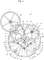
- the first escapement wheel 10 also begins to give a driving impulse to the balance wheel 26 via a tooth 66 of an impulse and rest toothing 68 which drives the first impulse paddle 30 (see figure 4 ).
- This driving impulse is called direct and tangential because it is given directly by the first escapement wheel 10 to the balance wheel plate 26 and the path of the tooth 66 catches up with that of the first impulse pallet 30 of the balance wheel plate 26 tangentially, which allows for almost punctual and frictionless contact.
- the arrival of the tooth 66 of the first escapement wheel 10 in contact with the first impulse pallet 30 of the balance wheel plate 26 marks the end of the first fall.
- FIG 5 is a top view of the natural escapement 1 in its position in which the first escapement wheel 10 imparts the impulse to the balance wheel 26, while the second lever 48b pivots about its pivot axis 52 and comes to bear against the second limiting stop 64.
- This movement is controlled by the anchor 34 which, driven by the balance pin 28, pivots about its anchor stem 36 in an anticlockwise direction.
- the first escape wheel 10 finishes giving an impulse to the balance wheel 26, which marks the start of the second fall. It can be seen that the tooth 66 of the first escape wheel 10 will no longer be in contact with the first impulse pallet 30 of the balance wheel 26. Furthermore, the second lever 48b is resting on the second limiting stop 64.
- FIG 7 is a top view of the natural escapement 1 in its other rest position in which the first escape wheel 10 rests on the first lever 48a, which marks the end of the second fall, while the balance wheel 26 finishes its alternation freely by rotating clockwise.
- FIG 8 is a top view of the natural exhaust 1 of the figure 1 in the case where the balance 20 has been removed, a situation schematically illustrated by representing the balance 20 in dotted lines.
- the first and second levers 48a, 48b of the anchor 34 are respectively provided with a first safety lever 84 and a second safety lever 86.
- the natural escapement 1 is in the position in which the second escapement wheel 16 will, by pivoting clockwise, act by one of the teeth of its impulse and rest toothing 70 on the second safety lever 86 carried by the second lever 48b and cause the pivoting of the anchor 34 to ensure the rest or blocking of the first escapement wheel 10 by pressing one of the teeth 66 of its impulse and rest toothing 68 on the part 88 of this anchor 34 which, in normal times, that is to say when the balance wheel 26 is present, ensures the function of a first stop pallet to temporarily block the first escapement wheel 10 during an operating cycle of the natural escapement 1.
- the situation illustrated in the figure 9 is symmetrical to that represented in the figure 8 , namely that it is the first escapement wheel 10 which, by pivoting counterclockwise, will act on the first safety lever 84 carried by the first lever 48a and cause the pivoting of the anchor 34 to ensure the rest or blocking of the second escapement wheel 10 by pressing one of the teeth of its impulse and rest toothing 70 on the part 90 of this anchor 34 which, in normal times, that is to say when the balance wheel plate 26 is present, ensures the function of a second stop pallet to temporarily block the second escapement wheel 16 during an operating cycle of the natural escapement 1.
- first and second levers 48a, 48b are not essential, the anchor 34 being able to comprise only the arms 46a, 46b, the first arm 46a having a geometry which ensures the function of a first stop pallet for temporarily blocking the first escapement wheel 10 during an operating cycle of the natural escapement 1, and the second arm 46b having a geometry which ensures the function of a second pallet. stop to temporarily block the second escape wheel 16 during the same operating cycle of the natural escapement 1.
- a reduction wheel can be arranged between the second escape wheel 2 and the first escape wheel 10.
- the first escape wheel 10 comprises a first drive toothing 12 by which it meshes with a second drive toothing 14 of the second escape wheel 16.
- first and second escape wheels 10, 16 each comprise an impulse and rest toothing 68, 70 by which they provide a direct and tangential driving impulse to the balance wheel 26.
- the drive toothing 12, 14 and impulse and rest toothing 68, 70 of each of the first and second escape wheels 10, 16 extend in a single plane or in two parallel planes.
- the first and second escape wheels 10, 16 are each in one piece.
Landscapes
- Physics & Mathematics (AREA)
- General Physics & Mathematics (AREA)
- Transmission Devices (AREA)
- Forklifts And Lifting Vehicles (AREA)
- Ladders (AREA)
Claims (18)
- Natürliche Hemmung (1) für Uhrwerke, das eine Abfolge von Funktionszyklen ausführt, die jeweils aus einer ersten und einer zweiten Schwingung einer Unruh (20) bestehen, während derer sich die Unruh (20) von einer ersten Extremposition zu einer zweiten Extremposition bewegt und dabei eine mittlere Ruhelage durchläuft, und dann von seiner zweiten Extremposition zu seiner ersten Extremposition zurückkehrt, indem er ein zweites Mal durch seine mittlere Ruhelage läuft. Diese Unruh (20) umfasst ein Unruhrad (22) auf einer Achse (24), an der eine Unruhscheibe (26) angebracht ist, die natürliche Hemmung (1) umfasst ein erstes Hemmungsrad mit mindestens einem ersten Zahnkranz, dieses erste Hemmungsrad ist so ausgelegt, dass es von einem Zahnrad des Uhrwerks angetrieben wird und wiederum ein zweites Hemmungsrad mit mindestens einem zweiten Zahnkranz antreibt, die ersten und zweiten Hemmungsräder bilden eine kinematische Kette, die mit einer Anker (34) zusammenarbeitet, der um einen Ankerstift (36) schwenken kann, die Unruhscheibe (26) verursacht das Schwenken des Ankers (34) bei jeder der ersten und zweiten Schwingungen, dieser Anker (34) ist so angeordnet, dass er das erste und das zweite Hemmungsrad während der zweiten bzw. ersten Schwingung eines Funktionszyklus vorübergehend blockiert, der Anker (34) umfasst ferner eine erste bzw. eine zweite Sicherheitsabhebung (84, 86), wobei diese ersten und zweiten Sicherheitsabhebungen (84, 86) so angeordnet sind, dass in Abwesenheit der Unruh (20) entweder das zweite oder das erste Hemmungsrad durch den Antrieb der zweiten oder der ersten Sicherheitsabhebung (84, 86) den Anker (34) schwenken lassen, um die Ruhe des ersten oder zweiten Hemmungsrads durch Anschlag dieses ersten oder zweiten Hemmungsrads an einem Teil (88, 90) des Ankers (34) sicherzustellen, das die Funktion einer Arretierpalette dieses ersten oder zweiten Hemmungsrads im normalen Betrieb der Hemmung (1) gewährleistet, die erste und zweite Sicherheitsabhebung (84, 86) sind so angeordnet, dass sie im normalen Betrieb der Hemmung (1), bei dem die Unruhscheibe (26) das Schwenken des Ankers (34) bewirkt, nicht mit den ersten und zweiten Hemmungsrädern in Kontakt kommen.
- Hemmung nach Anspruch 1, dadurch gekennzeichnet, dass der Anker (34) einen ersten und einen zweiten Arm (46a, 46b) umfasst, die so angeordnet sind, dass das erste und das zweite Hemmungsrad während der zweiten bzw. ersten Schwingung eines Funktionszyklus vorübergehend blockiert werden. Die erste Sicherheitsabhebung (84) ist am ersten Arm (46a) des Ankers (34) angebracht, während die zweite Sicherheitsabhebung (86) am zweiten Arm (46b) des Ankers (34) angebracht ist.
- Natürliche Hemmung nach Anspruch 2, dadurch gekennzeichnet, dass mindestens ein erster Hebel (48a), der um eine Schwenkachse (50) drehbar ist und auf dem die erste Sicherheitsabhebung (84) angebracht ist, mit dem ersten Arm (46a) des Ankers (34) über mindestens ein Schwenkgelenk (53) verbunden ist. Der Anker (34) umfasst einen zweiten Hebel (48b), der seinen zweiten Arm (46b) verlängert und auf dem die zweite Sicherheitsabhebung (86) angebracht ist. Diese ersten und zweiten Hebel (48a, 48b) sind so angeordnet, dass sie jeweils ein erstes und ein zweites Hemmungsrad (10, 16) blockieren, die die ersten und zweiten Hemmungsräder während der zweiten bzw. ersten Schwingung eines Funktionszyklus vorübergehend umfassen. Der Schwenkbereich der ersten und zweiten Hebel (48a, 48b) ist begrenzt.
- Hemmung nach einem der Ansprüche 2 und 3, dadurch gekennzeichnet, dass die Unruhscheibe (26) eine zweite Impulspalette (32) trägt, durch die diese Unruhscheibe (26) beim ersten Wechsel einen direkten und tangentialen Antrieb vom ersten Hemmungsrad erhält, und eine erste Impulspalette (30), durch die diese Unruhscheibe (26) beim zweiten Wechsel einen direkten und tangentialen Antrieb vom zweiten Hemmungsrad erhält.
- Natürliche Hemmung nach einem der Ansprüche 2 bis 4, dadurch gekennzeichnet, dass die Unruhscheibe (26) einen Unruhnagel (28) trägt, durch den diese Unruhscheibe (26) die Drehung des Ankers (34) bei jeder der ersten und zweiten Schwingungen bewirkt.
- Natürliche Hemmung (1) nach Anspruch 5, dadurch gekennzeichnet, dass die ersten und zweiten Hebel (48a, 48b) um die jeweiligen Schwenkachsen (50, 52) drehbar sind und jeweils an den ersten und zweiten Arm (46a, 46b) des Ankers (34) über mindestens ein Schwenkgelenk (53) angeschlossen sind.
- Natürliche Hemmung (1) nach Anspruch 6, dadurch gekennzeichnet, dass die mindestens eine Drehgelenke (53) jeweils aus einem Vorsprung (54, 56) bestehen, der in eine längliche Öffnung (58, 60) ragt.
- Natürliche Hemmung (1) nach einem der Ansprüche 5 bis 7, dadurch gekennzeichnet, dass der Schwenkbereich des Ankers (34) durch erste und zweite Begrenzungsanschläge (62, 64) begrenzt ist.
- Natürliche Hemmung (1) nach Anspruch 8, dadurch gekennzeichnet, dass die ersten und zweiten Begrenzungsanschläge (62, 64) Stifte sind.
- Natürliche Hemmung (1) nach Anspruch 8, dadurch gekennzeichnet, dass die ersten und zweiten Begrenzungsanschläge (62, 64) in einem festen Element des Uhrwerks gefertigt sind.
- Natürliche Hemmung (1) nach Anspruch 8, dadurch gekennzeichnet, dass der erste und zweite Begrenzungsanschlag (62, 64) Exzenter sind.
- Natürliche Hemmung (1) nach einem der Ansprüche 5 bis 11, dadurch gekennzeichnet, dass der erste Hebel (48a) aus einem Stück gefertigt ist und eine Geometrie aufweist, die die Funktion einer ersten Stopppalette übernimmt, um das erste Hemmungsrad (10) während der zweiten Schwingung vorübergehend zu blockieren, und der zweite Hebel (48b) aus einem Stück gefertigt ist und eine Geometrie aufweist, die die Funktion einer zweiten Stopppalette übernimmt, um das zweite Hemmungsrad (16) während der ersten Schwingung vorübergehend zu blockieren.
- Natürliche Hemmung (1) nach einem der Ansprüche 5 bis 12, dadurch gekennzeichnet, dass das erste Hemmungsrad (10) eine erste Antriebsverzahnung (12) umfasst, durch die es mit einer zweiten Antriebsverzahnung (14) des zweiten Hemmungsrads (16) in Eingriff steht, und dass die erste und zweite Hemmungsräder (10, 16) jeweils eine Impuls- und Ruheverzahnung (68, 70) umfassen, durch die sie der Unruhscheibe (26) einen direkten und tangentialen Antrieb verleihen. Die Antriebsverzahnungen (12, 14) und die Impuls- und Ruheverzahnungen (68, 70) der jeweiligen ersten und zweiten Hemmungsräder (10, 16) erstrecken sich in einer einzigen Ebene oder in zwei parallelen Ebenen.
- Natürliche Hemmung (1) nach Anspruch 13, dadurch gekennzeichnet, dass die erste und zweite Hemmungsräder (10, 16) jeweils einteilig sind.
- Natürliche Hemmung (1) nach einem der Ansprüche 5 bis 14, dadurch gekennzeichnet, dass der Anker (34) eine Gabel (40) umfasst, die aus einem ersten und einem zweiten Horn (42a, 42b) besteht, wobei die Unruhscheibe (26) durch ihren Unruhnagel (28) gegen das zweite Horn (42b) der Gabel (40) stößt und das Schwenken dieses Ankers (34) in einer ersten Richtung während der ersten Schwingung bewirkt, und gegen das erste Horn (42a) während der zweiten Schwingung, was das Schwenken des Ankers (34) in eine zweite Richtung entgegengesetzt zur ersten verursacht.
- Natürliche Hemmung (1) nach Anspruch 15, dadurch gekennzeichnet, dass die Gabel (40) einen Stift (44) trägt, der mit der Unruhscheibe (26) zusammenwirkt, um versehentliche Bewegungen der Gabel (40) während eines als Zusatzbogen bezeichneten Zeitraums zu verhindern.
- Uhrwerk mit natürlicher Hemmung (1) nach einem der Ansprüche 5 bis 16, dadurch gekennzeichnet, dass das Räderwerk des Uhrwerks, das das erste Hemmungsrad antreibt, ein Sekundenrad (2) ist, zwischen dem und dem ersten Hemmungsrad (10) ein weiteres Hemmungsrad (10) angeordnet ist.
- Uhrwerk mit einer natürliche Hemmung (1) nach einem der Ansprüche 1 bis 16.
Priority Applications (4)
| Application Number | Priority Date | Filing Date | Title |
|---|---|---|---|
| EP21215870.3A EP4198641B1 (de) | 2021-12-20 | 2021-12-20 | Natürliche hemmung für uhrwerk und uhrwerk, das eine solche uhrhemmung umfasst |
| US18/051,912 US12405574B2 (en) | 2021-12-20 | 2022-11-02 | Natural escapement for horological movement and horological movement comprising such an escapement |
| JP2022186187A JP7458460B2 (ja) | 2021-12-20 | 2022-11-22 | 計時器用ムーブメントのための自然エスケープ及びこのような自然エスケープを備える計時器用ムーブメント |
| CN202211648398.0A CN116300366B (zh) | 2021-12-20 | 2022-12-19 | 用于钟表机芯的自然式擒纵机构和包括这种擒纵机构的钟表机芯 |
Applications Claiming Priority (1)
| Application Number | Priority Date | Filing Date | Title |
|---|---|---|---|
| EP21215870.3A EP4198641B1 (de) | 2021-12-20 | 2021-12-20 | Natürliche hemmung für uhrwerk und uhrwerk, das eine solche uhrhemmung umfasst |
Publications (2)
| Publication Number | Publication Date |
|---|---|
| EP4198641A1 EP4198641A1 (de) | 2023-06-21 |
| EP4198641B1 true EP4198641B1 (de) | 2024-10-09 |
Family
ID=78957934
Family Applications (1)
| Application Number | Title | Priority Date | Filing Date |
|---|---|---|---|
| EP21215870.3A Active EP4198641B1 (de) | 2021-12-20 | 2021-12-20 | Natürliche hemmung für uhrwerk und uhrwerk, das eine solche uhrhemmung umfasst |
Country Status (4)
| Country | Link |
|---|---|
| US (1) | US12405574B2 (de) |
| EP (1) | EP4198641B1 (de) |
| JP (1) | JP7458460B2 (de) |
| CN (1) | CN116300366B (de) |
Families Citing this family (3)
| Publication number | Priority date | Publication date | Assignee | Title |
|---|---|---|---|---|
| JP7781970B2 (ja) * | 2023-07-12 | 2025-12-08 | ロレックス・ソシエテ・アノニム | 時計用の脱進機装置 |
| JP7778860B2 (ja) * | 2023-07-12 | 2025-12-02 | ロレックス・ソシエテ・アノニム | 時計用の脱進機装置 |
| EP4660713A1 (de) | 2024-06-03 | 2025-12-10 | Rolex Sa | Abgasvorrichtung für eine uhr |
Family Cites Families (18)
| Publication number | Priority date | Publication date | Assignee | Title |
|---|---|---|---|---|
| CH286913A (de) * | 1949-02-16 | 1952-11-15 | Siemens Ag | Uhrengangregler mit einem im Gangreglertakt bewegten Steigrad. |
| US2690048A (en) * | 1953-02-02 | 1954-09-28 | Cecil F Smith | Watch escapement |
| ATE447731T1 (de) * | 2007-04-18 | 2009-11-15 | Eta Sa Mft Horlogere Suisse | Ankerhemmung, die zwei hemmungszahnräder umfasst |
| DE602007004447D1 (de) | 2007-04-18 | 2010-03-11 | Eta Sa Mft Horlogere Suisse | Ankerhemmung für Uhren |
| DE602007008077D1 (de) * | 2007-05-30 | 2010-09-09 | Omega Sa | Ankerhemmung für Uhren |
| EP2487546B1 (de) | 2011-02-11 | 2021-06-30 | Montres Journe S.A. | Zweiachsige Hochleistungshemmung |
| EP2565730B1 (de) | 2011-08-29 | 2017-11-01 | ETA SA Manufacture Horlogère Suisse | Uhren-Hemmungsteilwerk |
| CN105849650B (zh) * | 2013-12-23 | 2018-09-21 | 尼瓦洛克斯-法尔股份有限公司 | 用于钟表的非接触式圆柱擒纵机构 |
| EP2887157B1 (de) * | 2013-12-23 | 2018-02-07 | The Swatch Group Research and Development Ltd. | Optimierte uhrhemmung |
| CH712807B8 (fr) | 2015-07-21 | 2020-10-30 | Cartier Int Ag | Mécanisme d'échappement. |
| CH712631B1 (fr) * | 2016-06-27 | 2020-02-28 | Mft Et Fabrique De Montres Et Chronometres Ulysse Nardin Le Locle S A | Echappement pour mouvement d'horlogerie. |
| EP3525046B1 (de) * | 2018-02-12 | 2024-07-10 | The Swatch Group Research and Development Ltd | Uhrwerkoszillator, der für winkelbeschleunigungen des tragens unempfindlich ist |
| EP3557334A1 (de) | 2018-04-17 | 2019-10-23 | Dominique Renaud SA | Uhrhemmungsmechanismus mit ruheanker, und uhr, die mit einem solchen hemmungsmechanismus ausgestattet ist |
| EP3882712B1 (de) * | 2020-03-18 | 2022-11-16 | The Swatch Group Research and Development Ltd | Mechanisches uhrwerk, dass mit einer uhrhemmung mit einem elastisch deformierbaren anker ausgestattet ist |
| EP3907566B1 (de) | 2020-05-05 | 2025-07-16 | Montres Breguet S.A. | Chronometerhemmung für uhren |
| EP3910425A1 (de) * | 2020-05-13 | 2021-11-17 | The Swatch Group Research and Development Ltd | Uhrwerk, das eine hemmung mit einem zahnrad und einer arretierung umfasst |
| EP4053641A1 (de) * | 2021-03-02 | 2022-09-07 | Montres Breguet S.A. | Natürliche hemmung für uhrwerk und uhrwerk, das eine solche uhrhemmung umfasst |
| EP4194959B1 (de) * | 2021-12-09 | 2025-09-17 | Montres Breguet S.A. | Natürliche hemmung für uhrwerk und uhrwerk, das eine solche uhrhemmung umfasst |
-
2021
- 2021-12-20 EP EP21215870.3A patent/EP4198641B1/de active Active
-
2022
- 2022-11-02 US US18/051,912 patent/US12405574B2/en active Active
- 2022-11-22 JP JP2022186187A patent/JP7458460B2/ja active Active
- 2022-12-19 CN CN202211648398.0A patent/CN116300366B/zh active Active
Also Published As
| Publication number | Publication date |
|---|---|
| EP4198641A1 (de) | 2023-06-21 |
| US20230251604A1 (en) | 2023-08-10 |
| JP7458460B2 (ja) | 2024-03-29 |
| CN116300366B (zh) | 2025-07-01 |
| JP2023091741A (ja) | 2023-06-30 |
| US12405574B2 (en) | 2025-09-02 |
| CN116300366A (zh) | 2023-06-23 |
Similar Documents
| Publication | Publication Date | Title |
|---|---|---|
| EP4198641B1 (de) | Natürliche hemmung für uhrwerk und uhrwerk, das eine solche uhrhemmung umfasst | |
| EP1941326B1 (de) | Chronometerhemmung für uhrenstück | |
| EP3499319B1 (de) | Kupplungswippe und kupplungsvorrichtung für uhrmechanismus | |
| EP2105806A1 (de) | Hemmungsmechanismus | |
| EP1983389A1 (de) | Hemmung, die zwei Hemmungsräder umfasst | |
| EP1983391A1 (de) | Ankerhemmung für Uhren | |
| EP2652559B1 (de) | Hebel und auslösemechanismus mit einem solchen hebel | |
| EP4194959B1 (de) | Natürliche hemmung für uhrwerk und uhrwerk, das eine solche uhrhemmung umfasst | |
| EP3338144B1 (de) | Bistabile mechanische vorrichtung für uhrwerke | |
| EP2697693B1 (de) | Uhrwerk | |
| EP4016195B1 (de) | Tourbillon für uhrwerk | |
| EP2444860B1 (de) | Reguliervorrichtung für Uhr | |
| EP1801668B1 (de) | Vorrichtung zum Galoppschutz für Uhrenhemmung | |
| EP4053644B1 (de) | Natürliche hemmung für uhrwerk und uhrwerk, das eine solche uhrhemmung umfasst | |
| CH718579B1 (fr) | Échappement naturel pour mouvement d'horlogerie et mouvement d'horlogerie comprenant un tel échappement. | |
| EP1645918A1 (de) | Vorrichtung zum Galoppschutz für Uhrenhemmung | |
| EP4105731B1 (de) | Natürliche hemmung für uhrwerk und uhrwerk, das eine solche uhrhemmung umfasst | |
| EP1276021B1 (de) | Hemmung für einen Zeitmesser | |
| EP1666990B1 (de) | Vorrichtung zum Galoppschutz für Uhrenhemmung | |
| CH717788B1 (fr) | Echappement naturel pour mouvement d'horlogerie et mouvement d'horlogerie comprenant un tel échappement. | |
| EP4053643B1 (de) | Natürliche hemmung für uhrwerk und uhrwerk, das eine solche uhrhemmung umfasst | |
| CH718266B1 (fr) | Échappement naturel pour mouvement d'horlogerie et mouvement d'horlogerie comprenant un tel échappement. | |
| EP4053642A1 (de) | Natürliche hemmung für uhrwerk und uhrwerk, das eine solche uhrhemmung umfasst | |
| CH717787B1 (fr) | Echappement naturel pour mouvement d'horlogerie et mouvement d'horlogerie comprenant un tel échappement. | |
| CH718400A2 (fr) | Echappement naturel pour mouvement d'horlogerie et mouvement d'horlogerie comprenant un tel échappement. |
Legal Events
| Date | Code | Title | Description |
|---|---|---|---|
| PUAI | Public reference made under article 153(3) epc to a published international application that has entered the european phase |
Free format text: ORIGINAL CODE: 0009012 |
|
| STAA | Information on the status of an ep patent application or granted ep patent |
Free format text: STATUS: THE APPLICATION HAS BEEN PUBLISHED |
|
| AK | Designated contracting states |
Kind code of ref document: A1 Designated state(s): AL AT BE BG CH CY CZ DE DK EE ES FI FR GB GR HR HU IE IS IT LI LT LU LV MC MK MT NL NO PL PT RO RS SE SI SK SM TR |
|
| P01 | Opt-out of the competence of the unified patent court (upc) registered |
Effective date: 20230701 |
|
| STAA | Information on the status of an ep patent application or granted ep patent |
Free format text: STATUS: REQUEST FOR EXAMINATION WAS MADE |
|
| 17P | Request for examination filed |
Effective date: 20231221 |
|
| RBV | Designated contracting states (corrected) |
Designated state(s): AL AT BE BG CH CY CZ DE DK EE ES FI FR GB GR HR HU IE IS IT LI LT LU LV MC MK MT NL NO PL PT RO RS SE SI SK SM TR |
|
| RIC1 | Information provided on ipc code assigned before grant |
Ipc: G04B 15/14 20060101ALI20240426BHEP Ipc: G04B 15/08 20060101AFI20240426BHEP |
|
| GRAP | Despatch of communication of intention to grant a patent |
Free format text: ORIGINAL CODE: EPIDOSNIGR1 |
|
| STAA | Information on the status of an ep patent application or granted ep patent |
Free format text: STATUS: GRANT OF PATENT IS INTENDED |
|
| INTG | Intention to grant announced |
Effective date: 20240611 |
|
| GRAS | Grant fee paid |
Free format text: ORIGINAL CODE: EPIDOSNIGR3 |
|
| GRAA | (expected) grant |
Free format text: ORIGINAL CODE: 0009210 |
|
| STAA | Information on the status of an ep patent application or granted ep patent |
Free format text: STATUS: THE PATENT HAS BEEN GRANTED |
|
| AK | Designated contracting states |
Kind code of ref document: B1 Designated state(s): AL AT BE BG CH CY CZ DE DK EE ES FI FR GB GR HR HU IE IS IT LI LT LU LV MC MK MT NL NO PL PT RO RS SE SI SK SM TR |
|
| REG | Reference to a national code |
Ref country code: CH Ref legal event code: EP |
|
| REG | Reference to a national code |
Ref country code: DE Ref legal event code: R096 Ref document number: 602021019894 Country of ref document: DE |
|
| REG | Reference to a national code |
Ref country code: IE Ref legal event code: FG4D Free format text: LANGUAGE OF EP DOCUMENT: FRENCH |
|
| REG | Reference to a national code |
Ref country code: LT Ref legal event code: MG9D |
|
| REG | Reference to a national code |
Ref country code: NL Ref legal event code: MP Effective date: 20241009 |
|
| REG | Reference to a national code |
Ref country code: AT Ref legal event code: MK05 Ref document number: 1731238 Country of ref document: AT Kind code of ref document: T Effective date: 20241009 |
|
| PG25 | Lapsed in a contracting state [announced via postgrant information from national office to epo] |
Ref country code: NL Free format text: LAPSE BECAUSE OF FAILURE TO SUBMIT A TRANSLATION OF THE DESCRIPTION OR TO PAY THE FEE WITHIN THE PRESCRIBED TIME-LIMIT Effective date: 20241009 |
|
| PG25 | Lapsed in a contracting state [announced via postgrant information from national office to epo] |
Ref country code: NL Free format text: LAPSE BECAUSE OF FAILURE TO SUBMIT A TRANSLATION OF THE DESCRIPTION OR TO PAY THE FEE WITHIN THE PRESCRIBED TIME-LIMIT Effective date: 20241009 |
|
| PG25 | Lapsed in a contracting state [announced via postgrant information from national office to epo] |
Ref country code: HR Free format text: LAPSE BECAUSE OF FAILURE TO SUBMIT A TRANSLATION OF THE DESCRIPTION OR TO PAY THE FEE WITHIN THE PRESCRIBED TIME-LIMIT Effective date: 20241009 Ref country code: PT Free format text: LAPSE BECAUSE OF FAILURE TO SUBMIT A TRANSLATION OF THE DESCRIPTION OR TO PAY THE FEE WITHIN THE PRESCRIBED TIME-LIMIT Effective date: 20250210 Ref country code: IS Free format text: LAPSE BECAUSE OF FAILURE TO SUBMIT A TRANSLATION OF THE DESCRIPTION OR TO PAY THE FEE WITHIN THE PRESCRIBED TIME-LIMIT Effective date: 20250209 |
|
| PG25 | Lapsed in a contracting state [announced via postgrant information from national office to epo] |
Ref country code: FI Free format text: LAPSE BECAUSE OF FAILURE TO SUBMIT A TRANSLATION OF THE DESCRIPTION OR TO PAY THE FEE WITHIN THE PRESCRIBED TIME-LIMIT Effective date: 20241009 |
|
| PG25 | Lapsed in a contracting state [announced via postgrant information from national office to epo] |
Ref country code: BG Free format text: LAPSE BECAUSE OF FAILURE TO SUBMIT A TRANSLATION OF THE DESCRIPTION OR TO PAY THE FEE WITHIN THE PRESCRIBED TIME-LIMIT Effective date: 20241009 |
|
| PG25 | Lapsed in a contracting state [announced via postgrant information from national office to epo] |
Ref country code: ES Free format text: LAPSE BECAUSE OF FAILURE TO SUBMIT A TRANSLATION OF THE DESCRIPTION OR TO PAY THE FEE WITHIN THE PRESCRIBED TIME-LIMIT Effective date: 20241009 |
|
| PG25 | Lapsed in a contracting state [announced via postgrant information from national office to epo] |
Ref country code: NO Free format text: LAPSE BECAUSE OF FAILURE TO SUBMIT A TRANSLATION OF THE DESCRIPTION OR TO PAY THE FEE WITHIN THE PRESCRIBED TIME-LIMIT Effective date: 20250109 |
|
| PG25 | Lapsed in a contracting state [announced via postgrant information from national office to epo] |
Ref country code: GR Free format text: LAPSE BECAUSE OF FAILURE TO SUBMIT A TRANSLATION OF THE DESCRIPTION OR TO PAY THE FEE WITHIN THE PRESCRIBED TIME-LIMIT Effective date: 20250110 Ref country code: LV Free format text: LAPSE BECAUSE OF FAILURE TO SUBMIT A TRANSLATION OF THE DESCRIPTION OR TO PAY THE FEE WITHIN THE PRESCRIBED TIME-LIMIT Effective date: 20241009 Ref country code: AT Free format text: LAPSE BECAUSE OF FAILURE TO SUBMIT A TRANSLATION OF THE DESCRIPTION OR TO PAY THE FEE WITHIN THE PRESCRIBED TIME-LIMIT Effective date: 20241009 |
|
| PGFP | Annual fee paid to national office [announced via postgrant information from national office to epo] |
Ref country code: CH Payment date: 20250101 Year of fee payment: 4 |
|
| PG25 | Lapsed in a contracting state [announced via postgrant information from national office to epo] |
Ref country code: PL Free format text: LAPSE BECAUSE OF FAILURE TO SUBMIT A TRANSLATION OF THE DESCRIPTION OR TO PAY THE FEE WITHIN THE PRESCRIBED TIME-LIMIT Effective date: 20241009 |
|
| PG25 | Lapsed in a contracting state [announced via postgrant information from national office to epo] |
Ref country code: RS Free format text: LAPSE BECAUSE OF FAILURE TO SUBMIT A TRANSLATION OF THE DESCRIPTION OR TO PAY THE FEE WITHIN THE PRESCRIBED TIME-LIMIT Effective date: 20250109 |
|
| PG25 | Lapsed in a contracting state [announced via postgrant information from national office to epo] |
Ref country code: SM Free format text: LAPSE BECAUSE OF FAILURE TO SUBMIT A TRANSLATION OF THE DESCRIPTION OR TO PAY THE FEE WITHIN THE PRESCRIBED TIME-LIMIT Effective date: 20241009 |
|
| PG25 | Lapsed in a contracting state [announced via postgrant information from national office to epo] |
Ref country code: MC Free format text: LAPSE BECAUSE OF FAILURE TO SUBMIT A TRANSLATION OF THE DESCRIPTION OR TO PAY THE FEE WITHIN THE PRESCRIBED TIME-LIMIT Effective date: 20241009 |
|
| PG25 | Lapsed in a contracting state [announced via postgrant information from national office to epo] |
Ref country code: DK Free format text: LAPSE BECAUSE OF FAILURE TO SUBMIT A TRANSLATION OF THE DESCRIPTION OR TO PAY THE FEE WITHIN THE PRESCRIBED TIME-LIMIT Effective date: 20241009 |
|
| REG | Reference to a national code |
Ref country code: DE Ref legal event code: R097 Ref document number: 602021019894 Country of ref document: DE |
|
| PG25 | Lapsed in a contracting state [announced via postgrant information from national office to epo] |
Ref country code: EE Free format text: LAPSE BECAUSE OF FAILURE TO SUBMIT A TRANSLATION OF THE DESCRIPTION OR TO PAY THE FEE WITHIN THE PRESCRIBED TIME-LIMIT Effective date: 20241009 |
|
| PG25 | Lapsed in a contracting state [announced via postgrant information from national office to epo] |
Ref country code: RO Free format text: LAPSE BECAUSE OF FAILURE TO SUBMIT A TRANSLATION OF THE DESCRIPTION OR TO PAY THE FEE WITHIN THE PRESCRIBED TIME-LIMIT Effective date: 20241009 |
|
| PG25 | Lapsed in a contracting state [announced via postgrant information from national office to epo] |
Ref country code: SK Free format text: LAPSE BECAUSE OF FAILURE TO SUBMIT A TRANSLATION OF THE DESCRIPTION OR TO PAY THE FEE WITHIN THE PRESCRIBED TIME-LIMIT Effective date: 20241009 |
|
| PG25 | Lapsed in a contracting state [announced via postgrant information from national office to epo] |
Ref country code: CZ Free format text: LAPSE BECAUSE OF FAILURE TO SUBMIT A TRANSLATION OF THE DESCRIPTION OR TO PAY THE FEE WITHIN THE PRESCRIBED TIME-LIMIT Effective date: 20241009 |
|
| PG25 | Lapsed in a contracting state [announced via postgrant information from national office to epo] |
Ref country code: IT Free format text: LAPSE BECAUSE OF FAILURE TO SUBMIT A TRANSLATION OF THE DESCRIPTION OR TO PAY THE FEE WITHIN THE PRESCRIBED TIME-LIMIT Effective date: 20241009 |
|
| PLBE | No opposition filed within time limit |
Free format text: ORIGINAL CODE: 0009261 |
|
| STAA | Information on the status of an ep patent application or granted ep patent |
Free format text: STATUS: NO OPPOSITION FILED WITHIN TIME LIMIT |
|
| PG25 | Lapsed in a contracting state [announced via postgrant information from national office to epo] |
Ref country code: LU Free format text: LAPSE BECAUSE OF NON-PAYMENT OF DUE FEES Effective date: 20241220 |
|
| PG25 | Lapsed in a contracting state [announced via postgrant information from national office to epo] |
Ref country code: SE Free format text: LAPSE BECAUSE OF FAILURE TO SUBMIT A TRANSLATION OF THE DESCRIPTION OR TO PAY THE FEE WITHIN THE PRESCRIBED TIME-LIMIT Effective date: 20241009 |
|
| 26N | No opposition filed |
Effective date: 20250710 |
|
| REG | Reference to a national code |
Ref country code: BE Ref legal event code: MM Effective date: 20241231 |
|
| PG25 | Lapsed in a contracting state [announced via postgrant information from national office to epo] |
Ref country code: BE Free format text: LAPSE BECAUSE OF NON-PAYMENT OF DUE FEES Effective date: 20241231 |
|
| PG25 | Lapsed in a contracting state [announced via postgrant information from national office to epo] |
Ref country code: IE Free format text: LAPSE BECAUSE OF NON-PAYMENT OF DUE FEES Effective date: 20241220 |
|
| REG | Reference to a national code |
Ref country code: CH Ref legal event code: U11 Free format text: ST27 STATUS EVENT CODE: U-0-0-U10-U11 (AS PROVIDED BY THE NATIONAL OFFICE) Effective date: 20260101 |
|
| PGFP | Annual fee paid to national office [announced via postgrant information from national office to epo] |
Ref country code: DE Payment date: 20251126 Year of fee payment: 5 |
|
| PGFP | Annual fee paid to national office [announced via postgrant information from national office to epo] |
Ref country code: GB Payment date: 20251119 Year of fee payment: 5 |
|
| PGFP | Annual fee paid to national office [announced via postgrant information from national office to epo] |
Ref country code: FR Payment date: 20251119 Year of fee payment: 5 |